EP4317896B1 - Ensemble réservoir - Google Patents
Ensemble réservoir Download PDFInfo
- Publication number
- EP4317896B1 EP4317896B1 EP22188338.2A EP22188338A EP4317896B1 EP 4317896 B1 EP4317896 B1 EP 4317896B1 EP 22188338 A EP22188338 A EP 22188338A EP 4317896 B1 EP4317896 B1 EP 4317896B1
- Authority
- EP
- European Patent Office
- Prior art keywords
- manifold
- tank
- inlet
- outlet
- tank assembly
- Prior art date
- Legal status (The legal status is an assumption and is not a legal conclusion. Google has not performed a legal analysis and makes no representation as to the accuracy of the status listed.)
- Active
Links
Images


Classifications
-
- F—MECHANICAL ENGINEERING; LIGHTING; HEATING; WEAPONS; BLASTING
- F28—HEAT EXCHANGE IN GENERAL
- F28F—DETAILS OF HEAT-EXCHANGE AND HEAT-TRANSFER APPARATUS, OF GENERAL APPLICATION
- F28F9/00—Casings; Header boxes; Auxiliary supports for elements; Auxiliary members within casings
- F28F9/02—Header boxes; End plates
- F28F9/0246—Arrangements for connecting header boxes with flow lines
- F28F9/0251—Massive connectors, e.g. blocks; Plate-like connectors
- F28F9/0253—Massive connectors, e.g. blocks; Plate-like connectors with multiple channels, e.g. with combined inflow and outflow channels
-
- F—MECHANICAL ENGINEERING; LIGHTING; HEATING; WEAPONS; BLASTING
- F28—HEAT EXCHANGE IN GENERAL
- F28D—HEAT-EXCHANGE APPARATUS, NOT PROVIDED FOR IN ANOTHER SUBCLASS, IN WHICH THE HEAT-EXCHANGE MEDIA DO NOT COME INTO DIRECT CONTACT
- F28D1/00—Heat-exchange apparatus having stationary conduit assemblies for one heat-exchange medium only, the media being in contact with different sides of the conduit wall, in which the other heat-exchange medium is a large body of fluid, e.g. domestic or motor car radiators
- F28D1/02—Heat-exchange apparatus having stationary conduit assemblies for one heat-exchange medium only, the media being in contact with different sides of the conduit wall, in which the other heat-exchange medium is a large body of fluid, e.g. domestic or motor car radiators with heat-exchange conduits immersed in the body of fluid
- F28D1/04—Heat-exchange apparatus having stationary conduit assemblies for one heat-exchange medium only, the media being in contact with different sides of the conduit wall, in which the other heat-exchange medium is a large body of fluid, e.g. domestic or motor car radiators with heat-exchange conduits immersed in the body of fluid with tubular conduits
- F28D1/053—Heat-exchange apparatus having stationary conduit assemblies for one heat-exchange medium only, the media being in contact with different sides of the conduit wall, in which the other heat-exchange medium is a large body of fluid, e.g. domestic or motor car radiators with heat-exchange conduits immersed in the body of fluid with tubular conduits the conduits being straight
- F28D1/0535—Heat-exchange apparatus having stationary conduit assemblies for one heat-exchange medium only, the media being in contact with different sides of the conduit wall, in which the other heat-exchange medium is a large body of fluid, e.g. domestic or motor car radiators with heat-exchange conduits immersed in the body of fluid with tubular conduits the conduits being straight the conduits having a non-circular cross-section
- F28D1/05366—Assemblies of conduits connected to common headers, e.g. core type radiators
- F28D1/05391—Assemblies of conduits connected to common headers, e.g. core type radiators with multiple rows of conduits or with multi-channel conduits combined with a particular flow pattern, e.g. multi-row multi-stage radiators
-
- F—MECHANICAL ENGINEERING; LIGHTING; HEATING; WEAPONS; BLASTING
- F28—HEAT EXCHANGE IN GENERAL
- F28F—DETAILS OF HEAT-EXCHANGE AND HEAT-TRANSFER APPARATUS, OF GENERAL APPLICATION
- F28F9/00—Casings; Header boxes; Auxiliary supports for elements; Auxiliary members within casings
- F28F9/02—Header boxes; End plates
- F28F9/0202—Header boxes having their inner space divided by partitions
- F28F9/0204—Header boxes having their inner space divided by partitions for elongated header box, e.g. with transversal and longitudinal partitions
-
- F—MECHANICAL ENGINEERING; LIGHTING; HEATING; WEAPONS; BLASTING
- F28—HEAT EXCHANGE IN GENERAL
- F28F—DETAILS OF HEAT-EXCHANGE AND HEAT-TRANSFER APPARATUS, OF GENERAL APPLICATION
- F28F9/00—Casings; Header boxes; Auxiliary supports for elements; Auxiliary members within casings
- F28F9/02—Header boxes; End plates
- F28F9/0246—Arrangements for connecting header boxes with flow lines
-
- F—MECHANICAL ENGINEERING; LIGHTING; HEATING; WEAPONS; BLASTING
- F28—HEAT EXCHANGE IN GENERAL
- F28F—DETAILS OF HEAT-EXCHANGE AND HEAT-TRANSFER APPARATUS, OF GENERAL APPLICATION
- F28F2275/00—Fastening; Joining
- F28F2275/04—Fastening; Joining by brazing
-
- F—MECHANICAL ENGINEERING; LIGHTING; HEATING; WEAPONS; BLASTING
- F28—HEAT EXCHANGE IN GENERAL
- F28F—DETAILS OF HEAT-EXCHANGE AND HEAT-TRANSFER APPARATUS, OF GENERAL APPLICATION
- F28F2275/00—Fastening; Joining
- F28F2275/12—Fastening; Joining by methods involving deformation of the elements
- F28F2275/122—Fastening; Joining by methods involving deformation of the elements by crimping, caulking or clinching
Definitions
- the present invention relates to a tank assembly.
- the present invention relates to a tank assembly for a vehicle heat exchanger. More specifically, the present invention relates to a tank assembly as defined in the preamble of claim 1, and as illustrated in US 2015/330681 .
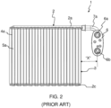
- a heat exchanger 1 for example, a condenser for a vehicle that includes a tank assembly, a heat exchanger core 4 and a connector block 6 as illustrated in FIG. 1 .
- the tank assembly includes a tank cover 2 and a tank header 3.
- the tank cover 2 includes channels 2a and 2b formed thereon that are longitudinally extending along length of the tank cover 2.
- the tank header 3 includes portions with apertures formed thereon.
- the tank cover 2 and the tank header 3 are assembled together by crimping and brazing so that the channels 2a and 2b of the tank cover 2 aligned to and in conjunction with the corresponding tank header portions define a first manifold, particularly, an inlet manifold and a second manifold, particularly, an outlet manifold.
- the second manifold For egress of the first heat exchange fluid from the heat exchanger after heat exchange with air surrounding the tubular elements 4a while passing through the tubular elements 4a, the second manifold delivers the first heat exchange fluid to an outlet port 6b of the connector block 6 via an outlet conduit 7b.
- the tubular elements 4a are divided into a first set of tubular elements 4a and a second set of tubular elements that are disposed adjacent to each other, wherein the second set of tubular elements are disposed behind the first set of tubular elements 4a, more specifically, downstream of the first set of tubular elements in second flow direction.
- the heat exchange fluid undergoes heat exchange with a second heat exchange fluid, particularly, air around the first set of tubular elements 4a as the first heat exchange fluid flows through the first set of tubular elements 4a.
- the second set of tubular elements receive the heat exchange fluid from the first set of tubular elements 4a via the intermediate manifold 2c configuring fluid communication between the tubular elements 4a, and the second heat exchange fluid undergoes further heat exchange as it passes through the second set of tubular elements.
- the second manifold collects the first heat exchange fluid from the second tubular elements, after the first heat exchange fluid had rejected heat to the air flowing across the tubular elements as it passes through the tubular elements.
- the connector block 6 with the inlet port 6a and the outlet port 6b for ingress and egress of fluid with respect to the heat exchanger 1 is generally mounted on a vehicle frame proximal to the first and second manifolds.
- the inlet and outlet conduits 7a and 7b configures fluid communication between the inlet port 6a and the first manifold and between the second manifold and the outlet port 6b respectively.
- use of inlet and outlet conduits 7a and 7b involves routing of the connecting inlet and outlet conduits 7a and 7b in limited space, particularly, in areas proximal to the lateral side of the heat exchanger 1.
- the inlet an outlet conduits 7a and 7b inherently cause an unutilized space "X" along lateral side of the heat exchanger 1.
- a tank assembly for a heat exchanger that eliminates connection conduits and renders the heat exchanger compact and addresses the packaging issues, particularly, along lateral sides of the heat exchanger and longitudinal direction of the first and second manifolds. Further, there is a need of a tank assembly for a heat exchanger that eliminates inlet and outlet conduits, thereby preventing problems such as energy losses and pressure drop between the inlet / outlet ports and corresponding first / second manifolds due to lengthy inlet and outlet connection conduits and bends in the inlet and outlet connection conduits. Further, there is a need for a tank assembly for a heat exchanger that improves efficiency and reliability of the heat exchanger by preventing fluid flow losses by eliminating connection conduits. There is a need of a tank assembly for a heat exchanger that reduces the number of parts, thereby reducing maintenance and enhancing reliability of the heat exchanger.
- a tank assembly for a heat exchanger in accordance with the present invention is defined in claim 1.
- the intermediate plate in conjunction with the end cover when assembled together define a first fluid flow passage and a second fluid flow passage.
- the first fluid flow passage defines fluid flow trajectory and fluid communication between the inlet and the first manifold.
- the second fluid flow passage defines fluid flow trajectory and fluid communication between the second manifold and the outlet.
- the first set of channels longitudinally extend along the length of the tank cover to free end thereof to define a first set of concave profiles at free end thereof.
- the tank header includes extension portions with a second set of concave profiles at the free end thereof. The profiles of the second set of concave profiles at free end thereof, the profiles of the second set of concave profiles being complementary to the respective profiles of the first set of concave profiles.
- extension portions with the second set of concave profiles are integrally formed with the header, whereas the first set of profiles are inherently formed at the free end of the respective first channels integrally formed with the tank cover.
- the first set of concave profiles get aligned to the second set of concave profiles to define respective manifold inlet and outlet as the tank cover is assembled to the tank header.
- the end cover includes a second set of channels and either one of tabs and notches.
- the second set of channels are spaced apart from each other and emanating from portions of the end cover corresponding to and aligned with sleeves formed on the intermediate plate and extending along plane of the end cover to one side of the end cover for configuring fourth set of concave profiles. Either one of tabs and notches for configuring crimping connection with the heat exchanger core.
- the fourth set of concave profiles get aligned with the third set of concave profiles and are held together within a second set of sleeves to define the inlet and outlet respectively.
- the second set of channels form fluid flow passages when the end cover is assembled to the intermediate cover.
- the first fluid flow passage configures fluid communication between the inlet and the corresponding first manifold and the second fluid flow passage configures fluid communication between the second manifold and the outlet.
- the inlet and the outlet are disposed along an axis extending orthogonally to the longitudinal axis of the first and second manifold and the longitudinal axis of the tubular elements, either one of the inlet and outlet is disposed underneath the other.
- At least a portion of the second set of channels about the diameter is formed on the intermediate plate.
- the inlet and outlet are asymmetrical about a plane passing through center of the second intermediate gap at extreme end of the second intermediate gap.
- a heat exchanger is disclosed in accordance with an embodiment of the present invention.
- the head exchanger includes a heat exchanger core, a tank assembly, an intermediate manifold and at least one of an intermediate plate and an end cover forming a connection system.
- the heat exchanger core includes a first set of tubular elements and a second set of tubular element disposed adjacent to the first set of tubular elements and respectively defining a first pass and a second pass.
- the tank assembly is as disclosed above and forms a first manifold and a second manifold disposed on same side of the heat exchanger core.
- the first manifold delivers fluid to the first set of tubular elements and the second manifold collects fluid from the second set of tubular elements after the fluid had undergone heat exchange while passing through the first and the second set of tubular elements.
- the connection system is formed with an inlet, an outlet and fluid flow passages.
- the first fluid flow passage configures fluid communication between the inlet and the first manifold and the second fluid flow passage configures fluid communication between the second manifold and the outlet.
- the intermediate manifold configures fluid communication between the first set of tubular elements and the second set of tubular elements to define U-flow trajectory of the fluid there-between to enable configuring of the first and second manifolds on the same side of the heat exchanger core.
- the tank header and the tank cover aligned with respect to the heat exchanger core are secured to each other by crimping and brazing to configure the manifolds with the manifold inlet and the manifold outlet. Further at least one of an intermediate plate and an end cover is orthogonally assembled with respect to longitudinal axis of the first and second manifolds to form the connection system.
- the connection system is formed with an inlet, an outlet and fluid flow passages.
- the first flow passage configures a curved fluid flow trajectory and fluid communication between the inlet and the first manifold.
- the second fluid flow passage also configures flow trajectory and fluid communication between the second manifold and the outlet.
- the inlet and the outlet extend orthogonally to the longitudinal axis of the manifold and the longitudinal axis of the tubular elements, wherein either one of the inlet and outlet is disposed underneath the other, thereby rendering the heat exchanger compact, particularly, along longitudinal side of the manifolds, thereby addressing packaging issues.
- Such configuration of fluid flow passages avoids inlet and outlet conduits and packaging, connection and routing issues faced due to the inlet and outlet conduits.
- tank assembly for a condenser for use in vehicle air conditioning is also applicable in any other heat exchanger used in vehicular or non-vehicular applications, where the first and the second manifold are required to be on same side of the heat exchanger and the heat exchanger is required to be compact, particularly, along longitudinal side of the manifold by eliminating connection conduits to address packaging issues.
- FIG. 3 illustrates an exploded view of the vehicle heat exchanger 200, hereinafter simply referred to as heat exchanger 200 configured with the tank assembly 100 of the present invention along with a connection system 80.
- FIG. 4 illustrates another isometric view of the heat exchanger 200 configured with the tank assembly 100 of the present invention.
- the tank assembly 100 includes an axis of elongation.
- the tank assembly 100 incudes a tank cover 10 as illustrated in FIG. 6 and a tank header 20 as illustrated in FIG. 7 .
- the tank cover 10 extends along the axis of extension of the tank assembly 100 and is formed with longitudinally extending first set of channels 10a and 10b.
- the first set of channels 10a and 10b longitudinally extend along the length of the tank cover 10 to free end thereof to define a first set of concave profiles 12a and 12b at free end thereof.
- the first set of channels 10a and 10b are separated by a first intermediate gap 10c.
- the intermediate gap 10c provides thermal insulation between fluid flowing through the respective channels of the first set of channel 10a and 10b.
- the tank header 20 includes a second set of concave profiles 26a and 26b at the free end thereof.
- the profiles of the second set of concave profiles 26a and 26b being complementary to the respective profiles of the first set of concave profiles 12a and 12b.
- the tank header 20 includes the extension portions 23a and 23b with the second set of concave profiles 26a and 26b are integrally formed with the header 20.
- the extension portions are extending beyond the heat exchanger core.
- the first set of profiles 12a and 12b are inherently formed at the free end of the respective first channels 10a and 10b integrally formed with the tank cover 10.
- the first set of concave profiles 12a and 12b get aligned to the second set of concave profiles 26a and 26b as the free end of the respective first channels 10a and 10b are aligned to the extension portions 23a and 23b to define respective manifold inlet and outlet 32a and 32b as illustrated in FIG. 5 .
- the manifold inlet 32a is for ingress of fluid into the first manifold 30a and the manifold outlet 32b is for egress of fluid from the second manifold 30b.
- the tank header 20 further includes apertures 22a and 22b configured on the respective portions 20a and 20b thereof.
- connection system 80 is formed with an inlet 50a, an outlet 50b and fluid flow passages 30c and 30d configuring fluid communication between the inlet and the outlet 50a and 50b and the respective first and second manifolds 30a and 30b.
- the connection system 80 can be configured by the intermediate plate 60 alone, the end cover 70 alone or by assembling together the intermediate plate 60 and the end cover 70.
- the intermediate plate 60 in conjunction with the end cover 70 when assembled together form the connection system 80.
- the connection system 80 is formed with the inlet 50a, the outlet 50b, the first fluid passage 30c and the second fluid flow passage 30d.
- the first fluid flow passage 30c defines fluid flow trajectory and fluid communication between the inlet 50a and the first manifold 30a
- the second fluid flow passage 30d defines fluid flow trajectory and fluid communication between the second manifold 30b and the outlet 50b.
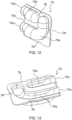
- the intermediate plate 60 is of rectangular configuration and includes a first set of sleeves 62a and 62b, a third set of concave profiles 64a and 64b and either one of tabs and notches 66 as illustrated in FIG. 11 .
- the first set of sleeves 62a and 62b are disposed along a first side of the intermediate plate 60.
- the intermediate plate 60 is so positioned with respect to the manifolds 30a and 30b that the first set of sleeves 62a and 62b are aligned to receive and hold respective manifold inlet 32a and outlet 32b.
- the third set of concave profiles 64a and 64b are configured along a second side of the intermediate plate 60 orthogonal to the first side. Either one of tabs and notches 66 are formed on the sides of the intermediate plate 60 for configuring crimping connection of the intermediate plate 60 with the heat exchanger core 40.
- the end cover 70 includes a second set of channels 70a and 70b and either one of tabs and notches 76.
- the second set of channels 70a and 70b are spaced apart from each other and emanating from portions of the end cover 70 corresponding to and aligned with first set of sleeves 62a and 62b formed on the intermediate plate 60.
- the second set of channels 70a and 70b extend along the plane of the end cover 70 to one side of the end cover 70 for configuring a fourth set of concave profiles 74a and 74b. Either one of tabs and notches 76 formed on the sides of the end cover 70 for configuring crimping connection with the heat exchanger core 40.
- the end cover 70 is secured to the heat exchanger core 40 with the intermediate plate 60 disposed between the end cover 70 and the manifolds 30a and 30b.
- the fourth set of concave profiles 74a and 74b get aligned with the third set of concave profiles 64a and 64b and are held together within a second set of sleeves 72a and 72b to define the inlet and outlet 50a and 50b respectively.
- the second set of channels 70a and 70b form the fluid flow passages 30c and 30d along the plane of the end plate 70.
- the first fluid flow passage 30c configures fluid communication between the inlet 50a and the first manifold 30a and the second fluid flow passage 30d configures fluid communication between the second manifold 30b and outlet 50b.
- the first and second fluid flow passages 30c and 30d are of varying cross section along the length thereof. Alternatively, cross section of the first and second fluid flow passages 30c and 30d is uniform along the length thereof.
- the channels of the second set of channels 70a and 70b are separated by a second intermediate gap 70c.
- the second intermediate gap 70c provides thermal insulation between fluid flowing through the channels of the second set of channels 70a and 70b.
- the second set of channels 70a and 70b are entirely formed on the end cover 70.
- connection system 80 formed by assembling the intermediate plate 60 and the end plate 70 is disposed orthogonally with respect to the longitudinal axis of the manifold 30a and 30b and is in fluid communication with the manifolds 30a and 30b.
- the first and the second fluid flow passages 30c and 30d are disposed along the plane of the connection system 80. At least one channel of the second set of channels 70a and 70b follows a curved profile while the other channel follows a straight profile.
- the first flow passage 30c formed by the channel 70a follows a curved profile between the inlet 50a and the manifold inlet 32a.
- the second fluid flow passage 30d formed by the channel 70b follows a straight path between the manifold outlet 32b and outlet 50b.
- the inlet and outlet 50a and 50b are symmetrical about a plane passing through center of the second intermediate gap 70c at extreme end of the second intermediate gap 70c.
- the inlet and outlet 50a and 50b are asymmetrical about a plane passing through center of the second intermediate gap 70c at extreme end of the second intermediate gap 70c, wherein the inlet 50a is larger than the outlet 50b.
- a heat exchanger 200 is disclosed in accordance with an embodiment of the present invention.
- the heat exchanger 200 includes a heat exchanger core 40, a tank assembly 100, an intermediate manifold 30e and a connection system 80 formed by at least one of an intermediate plate 60 and an end cover 70.
- the heat exchanger core 40 includes a first set of tubular elements 42a and a second set of tubular elements 42b disposed adjacent to the first set of tubular elements 42a and respectively defining a first pass and a second pass.
- the tank assembly 100 is as disclosed above and forms a first manifold 30a and a second manifold 30b disposed on same side of the heat exchanger core 40.
- the first manifold 30a delivers fluid to the first set of tubular elements 42a and the second manifold 30b collects fluid from the second set of tubular elements 42b after the fluid had undergone heat exchange while passing through the first and the second set of tubular elements 42a and 42b.
- the connection system 80 formed with an inlet 50a, an outlet 50b and fluid flow passages 30c and 30d.
- the first fluid flow passage 30c configures fluid communication between the inlet 50a and the first manifold 30a and the second fluid flow passage 30d configures fluid communication between the second manifold 30b and the outlet 50b.
- the intermediate manifold 30e configures fluid communication between the first set of tubular elements 42a and the second set of tubular elements 42b to define U-flow trajectory of the fluid there-between to enable configuring of the first and second manifolds 30a and 30b on the same side of the heat exchanger core.
Landscapes
- Engineering & Computer Science (AREA)
- Physics & Mathematics (AREA)
- Thermal Sciences (AREA)
- Mechanical Engineering (AREA)
- General Engineering & Computer Science (AREA)
- Heat-Exchange Devices With Radiators And Conduit Assemblies (AREA)
Claims (17)
- Ensemble réservoir (100) comprenant un axe d'allongement, dans lequel l'ensemble réservoir (100) comprend en outre :• un couvercle de réservoir (10) s'étendant le long de l'axe d'allongement de l'ensemble réservoir (100) et formé avec un premier groupe de canaux (10a et 10b) ; un collecteur de réservoir (20) comprenant des parties (20a et 20b) qui, conjointement avec le premier groupe de canaux (10a et 10b) formés sur le couvercle de réservoir (10), sont adaptées pour définir une première tubulure (30a) et une seconde tubulure (30b) lorsque le collecteur de réservoir (20) et le couvercle de réservoir (10) sont assemblés l'un par rapport à l'autre, le collecteur de réservoir (20) comprenant en outre des ouvertures (22a et 22b) configurées sur les parties respectives (20a et 20b) de celui-ci, dans lequel au moins un d'une plaque intermédiaire (60) et d'un couvercle d'extrémité (70) est orthogonalement assemblé par rapport à l'axe longitudinal des première et seconde tubulures (30a et 30b) pour former un système de raccordement (80), le système de raccordement (80) est formé avec une entrée (50a), une sortie (50b) et des passages d'écoulement de fluide (30c et 30d) configurant une communication fluidique entre l'entrée et la sortie (50a et 50b) et les première et seconde tubulures respectives (30a et 30b),dans lequel la plaque intermédiaire (60) de configuration rectangulaire comprend :• un groupe de profils concaves (64a) et (64b) configurés le long d'un second côté orthogonal à un premier de celle-ci ; et• des pattes ou des encoches (66) formées sur les côtés de celle-ci pour configurer un raccordement par sertissage avec le faisceau d'échangeur de chaleur (40), l'ensemble réservoir étant caractérisé en ce que la plaque intermédiaire (60) comprend en outre un premier groupe de manchons (62a et 62b) disposés le long du premier côté étant alignés avec et adaptés pour recevoir et retenir une entrée (32a) et une sortie (32b) de tubulure respectives.
- Ensemble réservoir (100) tel que revendiqué dans la revendication précédente, dans lequel la plaque intermédiaire (60) conjointement avec le couvercle d'extrémité (70), lorsqu'ils sont assemblés ensemble, définissent un premier passage de fluide (30c) et un second passage d'écoulement de fluide (30d), le premier passage d'écoulement de fluide (30c) définit une trajectoire d'écoulement de fluide et une communication fluidique entre l'entrée (50a) et la première tubulure (30a), alors que le second passage d'écoulement de fluide (30d) définit une trajectoire d'écoulement de fluide et une communication fluidique entre la seconde tubulure (30b) et la sortie (50b).
- Ensemble réservoir (100) tel que revendiqué dans de quelconques des revendications précédentes, dans lequel,• le premier groupe de canaux (10a) et (10b) s'étendent longitudinalement le long de la longueur du couvercle de réservoir (10) jusqu'à une extrémité libre de celui-ci pour définir un premier groupe de profils concaves (12a) et (12b) à l'extrémité libre de celui-ci ;• le collecteur de réservoir (20) comprend des parties d'extension (23a) et (23b) avec un deuxième groupe de profils concaves (26a) et (26b) à l'extrémité libre de celui-ci, les profils du deuxième groupe de profils concaves (26a) et (26b) étant complémentaires aux profils respectifs du premier groupe de profils concaves (12a) et (12b).
- Ensemble réservoir tel que revendiqué dans la revendication 3, dans lequel les parties d'extension (23a) et (23b) avec le deuxième groupe de profils concaves (26a) et (26b) sont formées de façon monobloc avec le collecteur (20), alors que le premier groupe de profils (12a) et (12b) sont formés de façon inhérente à l'extrémité libre des premiers canaux (10a) et (10b) respectifs formés de façon monobloc avec le couvercle de réservoir (10).
- Ensemble réservoir (100) tel que revendiqué dans la revendication 3, dans lequel le premier groupe de profils concaves (12a) et (12b) sont alignés avec le deuxième groupe de profils concaves (26a) et (26b) pour définir des entrée et sortie (32a) et (32b) de tubulures respectives quand le couvercle de réservoir (10) est assemblé avec le collecteur de réservoir (20).
- Ensemble réservoir tel que revendiqué dans de quelconques des revendications précédentes, dans lequel le couvercle d'extrémité (70) comprend :• un second groupe de canaux (70a) et (70b) espacés l'un de l'autre, provenant de parties du couvercle d'extrémité (70) correspondant au premier groupe de manchons (62a) et (62b), et alignées avec ceux-ci, formés sur la plaque intermédiaire (60) et s'étendant le long d'un plan du couvercle d'extrémité (70) jusqu'à un côté du couvercle d'extrémité (70) pour configurer un quatrième groupe de profils concaves (74a) et (74b) ;• des pattes ou des encoches (76) pour configurer un raccordement par sertissage avec le faisceau d'échangeur de chaleur (40),quand le couvercle d'extrémité (70) est assemblé avec le couvercle intermédiaire (60), le quatrième groupe de profils concaves (74a) et (74b) sont alignés avec le troisième groupe de profils concaves (64a) et (64b) et sont retenus ensemble à l'intérieur d'un second groupe de manchons (72a) et (72b) pour définir l'entrée et la sortie (50a) et (50b) respectivement.
- Ensemble réservoir (100) tel que revendiqué dans the la revendication 6, dans lequel le second groupe de canaux (70a) et (70b) forment les passages d'écoulement de fluide (30c) et (30d) lorsque le couvercle d'extrémité (70) est assemblé avec le couvercle intermédiaire (60), le premier passage d'écoulement de fluide (30c) configure une communication fluidique entre l'entrée (50a) et la première tubulure correspondante (30a) et le second passage d'écoulement de fluide (30d) configure une communication fluidique entre la seconde tubulure (30b) et la sortie (50b).
- Ensemble réservoir (100) tel que revendiqué dans de quelconques des revendications précédentes, dans lequel l'entrée (50a) et la sortie (50b) sont disposées le long d'un axe s'étendant orthogonalement à l'axe longitudinal des première et seconde tubulure (30a) et (30b) et à l'axe longitudinal des éléments tubulaires (42a) et (42b), l'une ou l'autre de l'entrée (50a) et de la sortie (50b) est disposée en dessous de l'autre.
- Ensemble réservoir (100) tel que revendiqué dans de quelconques des revendications précédentes, dans lequel le premier groupe de canaux (10a) et (10b) sont séparés par un premier espace intermédiaire (10c).
- Ensemble réservoir (100) tel que revendiqué dans la revendication 6, dans lequel le second groupe de canaux (70a) et (70b) sont séparés par un second espace intermédiaire (70c).
- Ensemble réservoir (100) tel que revendiqué dans la revendication 6, dans lequel au moins une partie du second groupe de canaux (70a) et (70b) est formée sur la plaque intermédiaire (60).
- Ensemble réservoir (100) tel que revendiqué dans la revendication 6, dans lequel au moins un canal du second groupe de canaux (70a) et (70b) suit un profil courbé alors que l'autre suit un profil droit.
- Ensemble réservoir (100) tel que revendiqué dans la revendication 10, dans lequel l'entrée et la sortie (50a) et (50b) sont symétriques relativement à un plan passant à travers un centre du second espace intermédiaire (70c) à l'extrémité finale du second espace intermédiaire (70c).
- Ensemble réservoir (100) tel que revendiqué dans la revendication 10, dans lequel l'entrée et la sortie (50a) et (50b) sont asymétriques relativement à un plan passant à travers un centre du second espace intermédiaire (70c) à l'extrémité finale du second espace intermédiaire (70c).
- Ensemble réservoir (100) tel que revendiqué dans la revendication 2, dans lequel les premier et second passages d'écoulement de fluide (30c) et (30d) sont de section transversale diverse le long de la longueur de ceux-ci.
- Ensemble réservoir (100) tel que revendiqué dans de quelconques des revendications précédentes, dans lequel des parties importantes des canaux du second groupe de canaux (70a) et (70b) sont parallèles l'une à l'autre, avec une partie importante d'un canal disposée en dessous de l'autre et la sortie (50b) disposée en dessous de l'entrée (50a).
- Échangeur de chaleur (200), comprenant :• un faisceau d'échangeur de chaleur (40) comprenant un premier groupe d'éléments tubulaires (42a) et un second groupe d'éléments tubulaires (42b) disposés de façon adjacente au premier groupe d'éléments tubulaires et définissant respectivement un premier chemin et un second chemin ;• un ensemble réservoir (100) tel que revendiqué dans de quelconques des revendications précédentes formant une première tubulure (30a) et une seconde tubulure (30b) disposée sur un même côté du faisceau d'échangeur de chaleur (40), la première tubulure (30a) étant adaptée pour livrer un fluide au premier groupe d'éléments tubulaires (42a) et la seconde tubulure (30b) étant adaptée pour collecter un fluide à partir du deuxième groupe d'éléments tubulaires (42b) après que le fluide a subi un échange de chaleur alors qu'il passe à travers le premier et le second groupe d'éléments tubulaires (42a) et (42b),• au moins un d'une plaque intermédiaire (60) et d'un couvercle d'extrémité (70) orthogonalement assemblé par rapport à un axe longitudinal des première et seconde tubulures (30a) et (30b) pour former un système de raccordement (80), le système de raccordement (80) étant formé avec une entrée (50a), une sortie (50b), et des passages d'écoulement de fluide (30c) et (30d), le premier passage d'écoulement de fluide (30c) étant adapté pour configurer une communication fluidique entre l'entrée (50a) et la première tubulure (30a) et le second passage d'écoulement de fluide (30d) étant adapté pour configurer une communication fluidique entre la seconde tubulure (30b) et la sortie (50b) ; et• une tubulure intermédiaire (30e) configurant une communication fluidique entre le premier groupe d'éléments tubulaires (42a) et le second groupe d'éléments tubulaires (42b) pour définir une trajectoire d'écoulement en U du fluide entre ceux-ci pour permettre la configuration des première et seconde tubulures (30a) et (30b) sur le même côté du faisceau d'échangeur de chaleur (40).
Priority Applications (1)
| Application Number | Priority Date | Filing Date | Title |
|---|---|---|---|
| EP22188338.2A EP4317896B1 (fr) | 2022-08-02 | 2022-08-02 | Ensemble réservoir |
Applications Claiming Priority (1)
| Application Number | Priority Date | Filing Date | Title |
|---|---|---|---|
| EP22188338.2A EP4317896B1 (fr) | 2022-08-02 | 2022-08-02 | Ensemble réservoir |
Publications (2)
| Publication Number | Publication Date |
|---|---|
| EP4317896A1 EP4317896A1 (fr) | 2024-02-07 |
| EP4317896B1 true EP4317896B1 (fr) | 2025-02-26 |
Family
ID=82786728
Family Applications (1)
| Application Number | Title | Priority Date | Filing Date |
|---|---|---|---|
| EP22188338.2A Active EP4317896B1 (fr) | 2022-08-02 | 2022-08-02 | Ensemble réservoir |
Country Status (1)
| Country | Link |
|---|---|
| EP (1) | EP4317896B1 (fr) |
Family Cites Families (4)
| Publication number | Priority date | Publication date | Assignee | Title |
|---|---|---|---|---|
| JP6358848B2 (ja) * | 2014-05-15 | 2018-07-18 | 株式会社ケーヒン・サーマル・テクノロジー | エバポレータ |
| FR3030710B1 (fr) * | 2014-12-18 | 2017-01-27 | Valeo Systemes Thermiques | Boite collectrice pour echangeur de chaleur et echangeur de chaleur equipe de ladite boite collectrice |
| DE102017218818A1 (de) * | 2017-10-20 | 2019-04-25 | Mahle International Gmbh | Wärmeübertrager |
| KR102791681B1 (ko) * | 2018-12-26 | 2025-04-08 | 한온시스템 주식회사 | 열교환기 |
-
2022
- 2022-08-02 EP EP22188338.2A patent/EP4317896B1/fr active Active
Also Published As
| Publication number | Publication date |
|---|---|
| EP4317896A1 (fr) | 2024-02-07 |
Similar Documents
| Publication | Publication Date | Title |
|---|---|---|
| CN101680689B (zh) | 热交换器 | |
| EP1397623B1 (fr) | Evaporateur, procede de fabrication afferent, collecteur pour ledit evaporateur et systeme de refrigeration | |
| US5086835A (en) | Heat exchanger | |
| US5184672A (en) | Heat exchanger | |
| US20050061489A1 (en) | Integrated multi-function return tube for combo heat exchangers | |
| CN112154297B (zh) | 集成式液体空气冷却的冷凝器和低温散热器 | |
| EP0709643A2 (fr) | Evaporateur pour réfrigérant | |
| EP3971508B1 (fr) | Échangeur de chaleur | |
| US20080105420A1 (en) | Parallel Flow Heat Exchanger With Crimped Channel Entrance | |
| AU2002304250A1 (en) | Evaporator, manufacturing method of the same, header for evaporator and refrigeration system | |
| EP2090851A1 (fr) | Échangeur de chaleur doté d'une chambre de mélange | |
| US6467536B1 (en) | Evaporator and method of making same | |
| WO2005066563A1 (fr) | Echangeur thermique multifluide et son procede de fabrication | |
| WO2006055277A1 (fr) | Echangeur de chaleur a minicanaux presentant des elements d'insertion restrictifs | |
| EP2257755A1 (fr) | Configuration de tube d'échangeur de chaleur pour distribution d'écoulement améliorée | |
| EP4194787A1 (fr) | Échangeur de chaleur | |
| JP2000154993A (ja) | 熱交換器 | |
| EP4198441A1 (fr) | Échangeur de chaleur | |
| EP2165141A1 (fr) | Échangeur de chaleur à écoulement parallèle avec connecteurs | |
| EP4317896B1 (fr) | Ensemble réservoir | |
| EP4317895B1 (fr) | Ensemble réservoir | |
| EP4317897A1 (fr) | Échangeur de chaleur | |
| EP4317884A1 (fr) | Échangeur de chaleur | |
| EP3760957B1 (fr) | Appareil de conditionnement d'air | |
| US20050120739A1 (en) | Integrated condenser/receiver |
Legal Events
| Date | Code | Title | Description |
|---|---|---|---|
| PUAI | Public reference made under article 153(3) epc to a published international application that has entered the european phase |
Free format text: ORIGINAL CODE: 0009012 |
|
| STAA | Information on the status of an ep patent application or granted ep patent |
Free format text: STATUS: THE APPLICATION HAS BEEN PUBLISHED |
|
| AK | Designated contracting states |
Kind code of ref document: A1 Designated state(s): AL AT BE BG CH CY CZ DE DK EE ES FI FR GB GR HR HU IE IS IT LI LT LU LV MC MK MT NL NO PL PT RO RS SE SI SK SM TR |
|
| STAA | Information on the status of an ep patent application or granted ep patent |
Free format text: STATUS: REQUEST FOR EXAMINATION WAS MADE |
|
| 17P | Request for examination filed |
Effective date: 20240806 |
|
| RBV | Designated contracting states (corrected) |
Designated state(s): AL AT BE BG CH CY CZ DE DK EE ES FI FR GB GR HR HU IE IS IT LI LT LU LV MC MK MT NL NO PL PT RO RS SE SI SK SM TR |
|
| GRAP | Despatch of communication of intention to grant a patent |
Free format text: ORIGINAL CODE: EPIDOSNIGR1 |
|
| STAA | Information on the status of an ep patent application or granted ep patent |
Free format text: STATUS: GRANT OF PATENT IS INTENDED |
|
| RIC1 | Information provided on ipc code assigned before grant |
Ipc: F28F 9/02 20060101AFI20240826BHEP |
|
| INTG | Intention to grant announced |
Effective date: 20240920 |
|
| GRAS | Grant fee paid |
Free format text: ORIGINAL CODE: EPIDOSNIGR3 |
|
| GRAA | (expected) grant |
Free format text: ORIGINAL CODE: 0009210 |
|
| STAA | Information on the status of an ep patent application or granted ep patent |
Free format text: STATUS: THE PATENT HAS BEEN GRANTED |
|
| AK | Designated contracting states |
Kind code of ref document: B1 Designated state(s): AL AT BE BG CH CY CZ DE DK EE ES FI FR GB GR HR HU IE IS IT LI LT LU LV MC MK MT NL NO PL PT RO RS SE SI SK SM TR |
|
| REG | Reference to a national code |
Ref country code: GB Ref legal event code: FG4D |
|
| REG | Reference to a national code |
Ref country code: CH Ref legal event code: EP |
|
| REG | Reference to a national code |
Ref country code: DE Ref legal event code: R096 Ref document number: 602022011031 Country of ref document: DE |
|
| REG | Reference to a national code |
Ref country code: IE Ref legal event code: FG4D |
|
| REG | Reference to a national code |
Ref country code: NL Ref legal event code: MP Effective date: 20250226 |
|
| PG25 | Lapsed in a contracting state [announced via postgrant information from national office to epo] |
Ref country code: RS Free format text: LAPSE BECAUSE OF FAILURE TO SUBMIT A TRANSLATION OF THE DESCRIPTION OR TO PAY THE FEE WITHIN THE PRESCRIBED TIME-LIMIT Effective date: 20250526 |
|
| PG25 | Lapsed in a contracting state [announced via postgrant information from national office to epo] |
Ref country code: FI Free format text: LAPSE BECAUSE OF FAILURE TO SUBMIT A TRANSLATION OF THE DESCRIPTION OR TO PAY THE FEE WITHIN THE PRESCRIBED TIME-LIMIT Effective date: 20250226 |
|
| PG25 | Lapsed in a contracting state [announced via postgrant information from national office to epo] |
Ref country code: PL Free format text: LAPSE BECAUSE OF FAILURE TO SUBMIT A TRANSLATION OF THE DESCRIPTION OR TO PAY THE FEE WITHIN THE PRESCRIBED TIME-LIMIT Effective date: 20250226 |
|
| PG25 | Lapsed in a contracting state [announced via postgrant information from national office to epo] |
Ref country code: ES Free format text: LAPSE BECAUSE OF FAILURE TO SUBMIT A TRANSLATION OF THE DESCRIPTION OR TO PAY THE FEE WITHIN THE PRESCRIBED TIME-LIMIT Effective date: 20250226 |
|
| REG | Reference to a national code |
Ref country code: LT Ref legal event code: MG9D |
|
| PG25 | Lapsed in a contracting state [announced via postgrant information from national office to epo] |
Ref country code: NO Free format text: LAPSE BECAUSE OF FAILURE TO SUBMIT A TRANSLATION OF THE DESCRIPTION OR TO PAY THE FEE WITHIN THE PRESCRIBED TIME-LIMIT Effective date: 20250526 Ref country code: IS Free format text: LAPSE BECAUSE OF FAILURE TO SUBMIT A TRANSLATION OF THE DESCRIPTION OR TO PAY THE FEE WITHIN THE PRESCRIBED TIME-LIMIT Effective date: 20250626 |
|
| PG25 | Lapsed in a contracting state [announced via postgrant information from national office to epo] |
Ref country code: NL Free format text: LAPSE BECAUSE OF FAILURE TO SUBMIT A TRANSLATION OF THE DESCRIPTION OR TO PAY THE FEE WITHIN THE PRESCRIBED TIME-LIMIT Effective date: 20250226 |
|
| PG25 | Lapsed in a contracting state [announced via postgrant information from national office to epo] |
Ref country code: HR Free format text: LAPSE BECAUSE OF FAILURE TO SUBMIT A TRANSLATION OF THE DESCRIPTION OR TO PAY THE FEE WITHIN THE PRESCRIBED TIME-LIMIT Effective date: 20250226 |
|
| PG25 | Lapsed in a contracting state [announced via postgrant information from national office to epo] |
Ref country code: PT Free format text: LAPSE BECAUSE OF FAILURE TO SUBMIT A TRANSLATION OF THE DESCRIPTION OR TO PAY THE FEE WITHIN THE PRESCRIBED TIME-LIMIT Effective date: 20250626 Ref country code: LV Free format text: LAPSE BECAUSE OF FAILURE TO SUBMIT A TRANSLATION OF THE DESCRIPTION OR TO PAY THE FEE WITHIN THE PRESCRIBED TIME-LIMIT Effective date: 20250226 |
|
| PG25 | Lapsed in a contracting state [announced via postgrant information from national office to epo] |
Ref country code: BG Free format text: LAPSE BECAUSE OF FAILURE TO SUBMIT A TRANSLATION OF THE DESCRIPTION OR TO PAY THE FEE WITHIN THE PRESCRIBED TIME-LIMIT Effective date: 20250226 Ref country code: GR Free format text: LAPSE BECAUSE OF FAILURE TO SUBMIT A TRANSLATION OF THE DESCRIPTION OR TO PAY THE FEE WITHIN THE PRESCRIBED TIME-LIMIT Effective date: 20250527 |
|
| REG | Reference to a national code |
Ref country code: AT Ref legal event code: MK05 Ref document number: 1770999 Country of ref document: AT Kind code of ref document: T Effective date: 20250226 |
|
| PG25 | Lapsed in a contracting state [announced via postgrant information from national office to epo] |
Ref country code: SE Free format text: LAPSE BECAUSE OF FAILURE TO SUBMIT A TRANSLATION OF THE DESCRIPTION OR TO PAY THE FEE WITHIN THE PRESCRIBED TIME-LIMIT Effective date: 20250226 |
|
| PG25 | Lapsed in a contracting state [announced via postgrant information from national office to epo] |
Ref country code: SM Free format text: LAPSE BECAUSE OF FAILURE TO SUBMIT A TRANSLATION OF THE DESCRIPTION OR TO PAY THE FEE WITHIN THE PRESCRIBED TIME-LIMIT Effective date: 20250226 |
|
| PG25 | Lapsed in a contracting state [announced via postgrant information from national office to epo] |
Ref country code: DK Free format text: LAPSE BECAUSE OF FAILURE TO SUBMIT A TRANSLATION OF THE DESCRIPTION OR TO PAY THE FEE WITHIN THE PRESCRIBED TIME-LIMIT Effective date: 20250226 |
|
| PG25 | Lapsed in a contracting state [announced via postgrant information from national office to epo] |
Ref country code: IT Free format text: LAPSE BECAUSE OF FAILURE TO SUBMIT A TRANSLATION OF THE DESCRIPTION OR TO PAY THE FEE WITHIN THE PRESCRIBED TIME-LIMIT Effective date: 20250226 |
|
| PG25 | Lapsed in a contracting state [announced via postgrant information from national office to epo] |
Ref country code: AT Free format text: LAPSE BECAUSE OF FAILURE TO SUBMIT A TRANSLATION OF THE DESCRIPTION OR TO PAY THE FEE WITHIN THE PRESCRIBED TIME-LIMIT Effective date: 20250226 |
|
| PG25 | Lapsed in a contracting state [announced via postgrant information from national office to epo] |
Ref country code: EE Free format text: LAPSE BECAUSE OF FAILURE TO SUBMIT A TRANSLATION OF THE DESCRIPTION OR TO PAY THE FEE WITHIN THE PRESCRIBED TIME-LIMIT Effective date: 20250226 Ref country code: CZ Free format text: LAPSE BECAUSE OF FAILURE TO SUBMIT A TRANSLATION OF THE DESCRIPTION OR TO PAY THE FEE WITHIN THE PRESCRIBED TIME-LIMIT Effective date: 20250226 |
|
| PG25 | Lapsed in a contracting state [announced via postgrant information from national office to epo] |
Ref country code: RO Free format text: LAPSE BECAUSE OF FAILURE TO SUBMIT A TRANSLATION OF THE DESCRIPTION OR TO PAY THE FEE WITHIN THE PRESCRIBED TIME-LIMIT Effective date: 20250226 |
|
| PG25 | Lapsed in a contracting state [announced via postgrant information from national office to epo] |
Ref country code: SK Free format text: LAPSE BECAUSE OF FAILURE TO SUBMIT A TRANSLATION OF THE DESCRIPTION OR TO PAY THE FEE WITHIN THE PRESCRIBED TIME-LIMIT Effective date: 20250226 |
|
| REG | Reference to a national code |
Ref country code: DE Ref legal event code: R097 Ref document number: 602022011031 Country of ref document: DE |
|
| PLBE | No opposition filed within time limit |
Free format text: ORIGINAL CODE: 0009261 |
|
| STAA | Information on the status of an ep patent application or granted ep patent |
Free format text: STATUS: NO OPPOSITION FILED WITHIN TIME LIMIT |
|
| REG | Reference to a national code |
Ref country code: CH Ref legal event code: L10 Free format text: ST27 STATUS EVENT CODE: U-0-0-L10-L00 (AS PROVIDED BY THE NATIONAL OFFICE) Effective date: 20260107 |
|
| 26N | No opposition filed |
Effective date: 20251127 |
|
| REG | Reference to a national code |
Ref country code: DE Ref legal event code: R119 Ref document number: 602022011031 Country of ref document: DE |
|
| REG | Reference to a national code |
Ref country code: CH Ref legal event code: H13 Free format text: ST27 STATUS EVENT CODE: U-0-0-H10-H13 (AS PROVIDED BY THE NATIONAL OFFICE) Effective date: 20260324 |
|
| PG25 | Lapsed in a contracting state [announced via postgrant information from national office to epo] |
Ref country code: MC Free format text: LAPSE BECAUSE OF FAILURE TO SUBMIT A TRANSLATION OF THE DESCRIPTION OR TO PAY THE FEE WITHIN THE PRESCRIBED TIME-LIMIT Effective date: 20250226 |
|
| PG25 | Lapsed in a contracting state [announced via postgrant information from national office to epo] |
Ref country code: LU Free format text: LAPSE BECAUSE OF NON-PAYMENT OF DUE FEES Effective date: 20250802 |
|
| PG25 | Lapsed in a contracting state [announced via postgrant information from national office to epo] |
Ref country code: CH Free format text: LAPSE BECAUSE OF NON-PAYMENT OF DUE FEES Effective date: 20250831 |