EP4318162B1 - Mobile vorrichtung und geschwindigkeitssteuerungsverfahren und -vorrichtung dafür sowie speichermedium - Google Patents
Mobile vorrichtung und geschwindigkeitssteuerungsverfahren und -vorrichtung dafür sowie speichermedium Download PDFInfo
- Publication number
- EP4318162B1 EP4318162B1 EP22938741.0A EP22938741A EP4318162B1 EP 4318162 B1 EP4318162 B1 EP 4318162B1 EP 22938741 A EP22938741 A EP 22938741A EP 4318162 B1 EP4318162 B1 EP 4318162B1
- Authority
- EP
- European Patent Office
- Prior art keywords
- mobile device
- speed
- distance
- line segment
- reference line
- Prior art date
- Legal status (The legal status is an assumption and is not a legal conclusion. Google has not performed a legal analysis and makes no representation as to the accuracy of the status listed.)
- Active
Links
Images




Classifications
-
- G—PHYSICS
- G05—CONTROLLING; REGULATING
- G05D—SYSTEMS FOR CONTROLLING OR REGULATING NON-ELECTRIC VARIABLES
- G05D1/00—Control of position, course, altitude or attitude of land, water, air or space vehicles, e.g. using automatic pilots
- G05D1/60—Intended control result
- G05D1/644—Optimisation of travel parameters, e.g. of energy consumption, journey time or distance
-
- G—PHYSICS
- G05—CONTROLLING; REGULATING
- G05D—SYSTEMS FOR CONTROLLING OR REGULATING NON-ELECTRIC VARIABLES
- G05D1/00—Control of position, course, altitude or attitude of land, water, air or space vehicles, e.g. using automatic pilots
- G05D1/20—Control system inputs
- G05D1/24—Arrangements for determining position or orientation
- G05D1/243—Means capturing signals occurring naturally from the environment, e.g. ambient optical, acoustic, gravitational or magnetic signals
-
- G—PHYSICS
- G05—CONTROLLING; REGULATING
- G05D—SYSTEMS FOR CONTROLLING OR REGULATING NON-ELECTRIC VARIABLES
- G05D1/00—Control of position, course, altitude or attitude of land, water, air or space vehicles, e.g. using automatic pilots
- G05D1/20—Control system inputs
- G05D1/24—Arrangements for determining position or orientation
- G05D1/246—Arrangements for determining position or orientation using environment maps, e.g. simultaneous localisation and mapping [SLAM]
-
- G—PHYSICS
- G05—CONTROLLING; REGULATING
- G05D—SYSTEMS FOR CONTROLLING OR REGULATING NON-ELECTRIC VARIABLES
- G05D1/00—Control of position, course, altitude or attitude of land, water, air or space vehicles, e.g. using automatic pilots
- G05D1/60—Intended control result
- G05D1/617—Safety or protection, e.g. defining protection zones around obstacles or avoiding hazards
- G05D1/622—Obstacle avoidance
-
- G—PHYSICS
- G05—CONTROLLING; REGULATING
- G05D—SYSTEMS FOR CONTROLLING OR REGULATING NON-ELECTRIC VARIABLES
- G05D1/00—Control of position, course, altitude or attitude of land, water, air or space vehicles, e.g. using automatic pilots
- G05D1/60—Intended control result
- G05D1/65—Following a desired speed profile
-
- G—PHYSICS
- G05—CONTROLLING; REGULATING
- G05D—SYSTEMS FOR CONTROLLING OR REGULATING NON-ELECTRIC VARIABLES
- G05D2107/00—Specific environments of the controlled vehicles
- G05D2107/70—Industrial sites, e.g. warehouses or factories
-
- G—PHYSICS
- G05—CONTROLLING; REGULATING
- G05D—SYSTEMS FOR CONTROLLING OR REGULATING NON-ELECTRIC VARIABLES
- G05D2109/00—Types of controlled vehicles
- G05D2109/10—Land vehicles
-
- G—PHYSICS
- G05—CONTROLLING; REGULATING
- G05D—SYSTEMS FOR CONTROLLING OR REGULATING NON-ELECTRIC VARIABLES
- G05D2111/00—Details of signals used for control of position, course, altitude or attitude of land, water, air or space vehicles
- G05D2111/10—Optical signals
Definitions
- an embodiment of the present disclosure provides a speed control method applied to a mobile device, and the method includes:
- the first determining module is configured to:
- the second determining module is configured to:
- the controlling module is configured to: control the mobile device to move at the target speed in response to the target speed satisfying a preset speed range.
- an embodiment of the present disclosure provides a mobile device, including:
- an embodiment of the present disclosure provides a storage medium, which stores computer instructions for causing a computer to perform the method according to any embodiment in the first aspect.
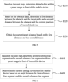
- the speed control method includes: obtaining the cost map of the moving area and the target path of the mobile device moving in the moving area; based on the cost map, determining the current target distance between the mobile device and the obstacle, and the current turning curvature; determining the target speed based on the current target distance, the current turning curvature, and the maximum limiting speed; and controlling the mobile device to move at the target speed.
- the current moving speed is controlled by the current target distance between the mobile device and the obstacle, and the current turning curvature, so that the moving speed can be adaptively adjusted according to the current road condition, and the risk of an accident can be reduced.
- mobile devices such as sweeping robots, logistics robots, food delivery robots, and foot robots can move autonomously in preset operation spaces to achieve corresponding operation requirements.
- the speed control of mobile devices is an important part of motion planning. If the mobile devices move too fast, the risk of an accident and losses caused by the accident will increase. If the mobile devices move too slowly, their operation efficiency will also decreases.
- a working area of a mobile device can be divided in advance to perform speed limiting.
- the whole moving area of the mobile device can be divided into three zones A, B and C in advance.
- Different maximum limiting speeds are set in advance for each zone according to obstacles, mobile device density and other factors, so that when the mobile device runs to a certain zone, the mobile device will operate according to a maximum limiting speed specified for the zone.
- the mobile device cannot adaptively adjust the moving speed based on changes of obstacles, and can only operate according to the speed limited for the zone.
- the mobile device still operates according to the low limiting speed, resulting in a decrease in the operation efficiency of the mobile device.
- the mobile device still operates according to the high limiting speed, resulting in a significant increase in the risk of collision, scratch, and other accidents on the mobile device.
- the mobile device can only achieve the control of the moving speed in the set zones, and cannot achieve speed adaptive control for other moving areas, so the adaptability of the mobile device is very poor.
- the present disclosure provides a mobile device, a speed control method and apparatus thereof, and a storage medium, aiming at achieving speed adaptive control of the mobile device, reducing the risk of an accident of the mobile device, and improving the safety and moving efficiency of the mobile device.
- an embodiment of the present disclosure provides a speed control method, which can be applied to a mobile device.
- the mobile device in the embodiment of the present disclosure can be any type of device with autonomous motion capability suitable for implementation, such as a foot robot, a sweeping robot, a logistics robot, a food delivery robot, an intelligent mobile trash can, which in not limited in the present disclosure.
- a mobile device 600 includes a processor 601, a memory 602, a scene perception system 604, and a driving device 605.
- the processor 601, the memory 602, the scene perception system 604, and the driving device 605 establish a communicable connection between any two of them through a bus 603.
- the processor 601 can be any type of processor with one or more processing cores.
- the processor 601 can perform single-threaded or multi-threaded operations for parsing instructions to perform operations such as obtaining data, performing logical operation functions, and issuing operation processing results.
- the scene perception system 604 may be a simultaneous localization and mapping (SLAM) system.
- the SLAM system can include a plurality of sensors, such as a monocular camera, a binocular camera, a lidar, an inertial measurement unit (IMU) sensor, a time of flight (ToF) sensor. Through these sensors, the data of the mobile device in the process of movement are collected in real time, and based on the collected data, the device localization and mapping are realized by SLAM algorithm.
- a line connecting between the current position of the mobile device and the position of the obstacle can also be directly used as the current target distance, that is, it is not necessary to calculate the first and second distance components mentioned above, which is not limited in the present disclosure.
- two normal line segments spaced by a preset distance made for the target path can be used as reference line segments, namely a first reference line segment and a second reference line segment.
- first reference line segment and the second reference line segment are always perpendicular to the target path, when the target path is a straight line, the first reference line segment and the second reference line segment are in a parallel positional relationship and will not intersect.
- the first reference line segment and the second reference line segment are no longer parallel to each other, and as the curvature of the target path increases, the first reference line segment and the second reference line segment will intersect and form an angle.
- the larger the curvature of the target path the greater the value of the angle.
- the turning curvature of the mobile device when moving along the target path currently can be determined by the value of the angle.
- a target speed of the mobile device is determined based on the current target distance, the current turning curvature, and a maximum limiting speed of the mobile device.
- the maximum limiting speed V max of the mobile device represents a maximum operating speed allowed for the mobile device.
- the speed control task of the mobile device can be understood as a process of adjusting the maximum limiting speed of the mobile device. By adaptively adjusting the maximum limiting speed of the mobile device, the mobile device can maintain an appropriate moving speed under different road conditions.
- the maximum limiting speed V max of the mobile device can be comprehensively adjusted based on the target distance and the turning curvature to obtain the corresponding target speed.
- the target distance reflects the proximity between the mobile device and the obstacle.
- the smaller the target distance the higher the risk of an accident for the mobile device, and thus the lower the target speed should be.
- the turning curvature reflects a bending degree of the movement path of the mobile device itself. The greater the turning curvature, the higher the risk of an accident for the mobile device, and thus the lower the target speed should be.
- a straight-line travelling speed component of the mobile device can be determined based on the current target distance and the maximum limiting speed, and a turning speed component of the mobile device can be determined based on the current turning curvature and the maximum limiting speed. Then, the straight-line travelling speed component and the turning speed component are weighted and summed to obtain the final target speed. This will be explained in the following implementations of the present disclosure and will not be elaborated herein.
- the mobile device after determining the target speed of the mobile device, the mobile device can be controlled to move at that target speed.
- the processor 601 can generate corresponding control instructions based on the target speed and send the control instructions to the driving device 605.
- the driving device 605 outputs a motor torque according to the control instructions, thereby controlling the mobile device to move at the target speed.
- the current moving speed is controlled by the current target distance between the mobile device and the obstacle, and the current turning curvature, so that the moving speed can be adjusted adaptively according to the current road condition, and the risk of an accident can be reduced.
- speed control not only the target distance between the mobile device and the obstacle, but also the bending degree of the target path of the mobile device itself are considered, and thus the risk of an accident caused by a blind area of vision at turns can be reduced, and speed control effect can be further improved.
- obtaining the cost map of the moving area and the target path includes steps S310 to S330.
- scene data of the moving area collected through one or more sensors of the mobile device is obtained.
- the scene perception system 604 can collect the scene data in a current state.
- the scene perception system 604 is a VSLAM system based on computer vision.
- the scene data collected by the VSLAM system can include scene image data of the moving area in front of the mobile device, physical depth data, and motion information of the mobile device itself.
- the scene perception system 604 can also be other systems, such as lidar, which is not limited in the present disclosure.
- S320 localization on the mobile device and mapping are performed based on the scene data to obtain the current position of the mobile device and an environment map.
- an simultaneous localization and mapping (SLAM) algorithm can be used to locate the mobile device and reconstruct an map of the moving area in front of the mobile device, so as to obtain the current position of the mobile device and the environment map of the moving area.
- SLAM simultaneous localization and mapping
- the cost map of the moving area is obtained based on obstacle information in the environment map, and the target path of the mobile device is determined based on the cost map and the current position.
- the cost map is a virtual map used for path planning of the mobile device.
- the cost map can be a local 2D cost map within a preset range in front of the mobile device.
- the preset range in front of the mobile device refers to an area with a preset forward-looking range in front of the moving direction of the mobile device.
- the preset range described in the present disclosure refers to an area with a preset forward-looking range of the mobile device.
- a preset range 400 in front of the mobile device 600 is an area with a rectangular range shown by the dashed line in the figure. As the mobile device 600 moves, the preset range 400 is always located in front of the moving direction of the mobile device 600.
- the size of the preset range is 2R*P, where specific values of R and P can be set according to factors such as the size of the mobile device and requirements of the scene, which is not limited in the present disclosure.
- the preset range 400 in FIG. 4 is only an example of the embodiment of the present disclosure.
- the preset range 400 is not limited to the area with the rectangular range shown in FIG. 4 , but can also be, for example, an area with a sector range, etc., which is not limited in the present disclosure.
- the obstacle data can be determined based on the cost map.
- the obstacle data includes position coordinates of the obstacle in an image coordinate system.
- the current target distance between the mobile device and the obstacle includes two mutually perpendicular components, namely a first distance and a second distance.
- the first distance refers to a distance that the obstacle is perpendicular to the target path
- the second distance refers to a distance between the obstacle and the mobile device in a direction parallel to the target path.
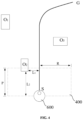
- an obstacle O 2 is located within the preset range 400, so based on obstacle data, a first distance L 1 between the obstacle and the target path, and a second distance L 2 between the obstacle and the mobile device, can be determined on the cost map.
- the first distance refers to the shortest distance L 1 obtained by making the obstacle O 2 perpendicular to the target path SG.
- the second distance refers to the shortest distance L 2 between the obstacle O 2 and the mobile device 600 in the direction parallel to the target path. That is, the first distance L 1 and the second distance L 2 are perpendicular to each other.
- the current target distance between the mobile device and the obstacle includes the first distance L 1 and the second distance L 2 mentioned above. Therefore, after obtaining the first distance L 1 and the second distance L 2 , the first distance L 1 and the second distance L 2 are determined as the current target distance between the mobile device and the obstacle.
- determining the current turning curvature of the mobile device when moving along the target path includes steps S610 and S620.
- a first reference line segment and a second reference line segment within a preset range in front of the mobile device are determined.
- the current turning curvature of the mobile device is determined based on an angle between the first reference line segment and the second reference line segment.
- two normal line segments spaced by a preset distance made for the target path can be used as reference line segments, respectively defined as the first reference line segment and the second reference line segment.
- reference line segments respectively defined as the first reference line segment and the second reference line segment.
- first reference line segment K 1 and the second reference line segment K 2 are spaced by a preset distance d. It can be understood that the length of the first reference line segment K 1 and the second reference line segment K 2 can be set according to specific scene requirements, which is not limited in the present disclosure.
- the target path is a straight line. Since the first reference line segment K 1 and the second reference line segment K 2 are both perpendicular to the target path, the first reference line segment K 1 and the second reference line segment K 2 are parallel to each other, and they will not intersect, and there will be no angle.
- the target path ahead is a curve. Since the first reference line segment K 1 and the second reference line segment K 2 are always perpendicular to the target path, the first reference line segment K 1 and the second reference line segment K 2 will intersect, with an intersection point of Q and an angle ⁇ between the two.
- both the first reference line segment K 1 and the second reference line segment K 2 are line segments, that is, they are not infinitely extended, even if the first reference line segment K 1 and the second reference line segment K 2 are no longer parallel due to the bending of the target path, the first reference line segment K 1 and the second reference line segment K 2 will not intersect when the curvature is very small.
- a curvature boundary of the target path when ends of the first reference line segment K 1 and the second reference line segment K 2 intersect can be adjusted, which can be understood and fully implemented by those skilled in the art, and will not be further elaborated in the present disclosure.
- position coordinates of an intersection point Q of the first reference line segment K 1 and the second reference line segment K 2 can be determined.
- the target distance between the current position of the mobile device and the obstacle, and the turning curvature can be determined, and then the maximum limiting speed of the mobile device can be adjusted based on the target distance and the turning curvature, which will be described in detail below.
- determining the target speed of the mobile device based on the current target distance, the current turning curvature, and the maximum limiting speed includes steps S810 to S830.
- a straight-line travelling speed component of the mobile device is determined based on the current target distance and the maximum limiting speed.
- the current target distance is positively correlated with the straight-line travelling speed component. That is, the greater the current target distance, it means that the farther the mobile device is currently from the obstacle, the lower the risk of an accident, and thus the greater the straight-line travelling speed component. On the contrary, the smaller the current target distance, it means that the closer the mobile device is currently from the obstacle, the higher the risk of an accident, and thus the smaller the straight-line travelling speed component.
- a corresponding relationship between the current target distance and the straight-line travelling speed component can be established in advance, and the size of the straight-line travelling speed component can be determined by looking up the corresponding relationship.
- the current target distance includes the first distance L 1 and the second distance L 2 . Therefore, the straight-line travelling speed component in an embodiment of the present disclosure also includes a first speed component and a second speed component, which will be described with reference to the embodiment in FIG. 9 .
- determining the straight-line travelling speed component of the mobile device based on the current target distance and the maximum limiting speed includes steps S811 to S813.
- the first speed component of the mobile device is determined based on the first distance and the maximum limiting speed.
- V 1 represents the first speed component
- V 2 represents the second speed component
- L 1 represents the first distance
- L 2 represents the second distance
- R represents half the width of the preset range
- P represents the length of the preset range
- V max represents the maximum limiting speed of the mobile device.
- the first speed component V 1 and the second speed component V 2 of the mobile device can be calculated, and then the first speed component V 1 and the second speed component V 2 are determined as the straight-line travelling speed component.
- the maximum limiting speed can be adaptively adjusted based on the size of the turning curvature to obtain the turning speed component.
- the turning curvature is negatively correlated with the turning speed component. That is, the larger the current turning curvature, it means that the higher the risk that the mobile device will have an accident, so the turning speed component should be smaller. On the contrary, the smaller the current turning curvature, it means that the lower the risk that the mobile device will have an accident, and the greater the turning speed component.
- V 3 represents the turning speed component
- ⁇ represents the current turning curvature
- V max represents the maximum limiting speed
- the straight-line travelling speed component represents a straight-line travelling speed of the mobile device under the current road condition
- the turning speed component represents a turning speed of the mobile device under the current road condition.
- V 1 V max
- V 2 V max
- V 3 V max
- the target speed V obtained by substituting into the formula (4) should also be smaller than V max , which means that the speed of the mobile device should be reduced adaptively.
- the first speed component V 1 , the second speed component V 2 , and the turning speed component V 3 calculated based on the aforementioned formulas (1) to (3) are smaller than V max .
- the target speed V obtained by substituting into the formula (4) should also be smaller than V max , which means that the speed of the mobile device should be reduced adaptively.
- the speed of the mobile device is not only adjusted based on the distance between the mobile device and the obstacle, but also adjusted in combination with the turning curvature. During the turning process, even if there is no obstacle in front of the mobile device, the speed of the mobile device will still be reduced, so as to avoid overturning caused by turning too fast, or reduce the risk of an accident caused by a blind area of vision at turns.
- the mobile device can be controlled to move at the minimum speed limit V min .
- the target speed is greater than the maximum limiting speed V max , the mobile device can be controlled to move at the maximum limiting speed V max .
- the target speed is within the preset speed range [V min , V max ], the mobile device can be controlled to move at the target speed.
- V min , V max The specific value of the preset speed range [V min , V max ] can be set by those skilled in the art according to specific application scenarios, and are not limited in the present disclosure.
- the current moving speed is controlled by the current target distance between the mobile device and the obstacle, and the current turning curvature, so that the moving speed can be adaptively adjusted according to the current road condition, and the risk of an accident can be reduced.
- speed control not only the target distance between the mobile device and the obstacle, but also the bending degree of the target path of the mobile device itself is considered, so as to reduce the risk of an accident caused by a blind area of vision at turns, and further improve the speed control effect.
- the obtaining module 10 is configured to:
- the first determining module 20 is configured to:
- the first determining module 20 is configured to:
- the first determining module 20 is configured to:
- the second determining module 30 is configured to:
- the second determining module 30 is configured to:
- the controlling module 40 is configured to: control the mobile device to move at the target speed in response to the target speed satisfying a preset speed range.
- the current moving speed is controlled by the current target distance between the mobile device and the obstacle, and the current turning curvature, so that the moving speed can be adaptively adjusted according to the current road condition, and the risk of an accident can be reduced.
- speed control not only the target distance between the mobile device and the obstacle, but also the bending degree of the target path of the mobile device itself is considered, so as to avoid overturning caused by too fast turning speed, reduce the risk of an accident caused by a blind area of vision at turns, and further improve the speed control effect.
- an embodiment of the present disclosure provides a mobile device, including:
- the current moving speed is controlled by the current target distance between the mobile device and the obstacle, and the current turning curvature, so that the moving speed can be adaptively adjusted according to the current road condition, and the risk of an accident can be reduced.
- speed control not only the target distance between the mobile device and the obstacle, but also the bending degree of the target path of the mobile device itself is considered, so as to avoid overturning caused by too fast turning speed, reduce the risk of an accident caused by a blind area of vision at turns, and further improve the speed control effect.
Landscapes
- Engineering & Computer Science (AREA)
- Aviation & Aerospace Engineering (AREA)
- Radar, Positioning & Navigation (AREA)
- Remote Sensing (AREA)
- Physics & Mathematics (AREA)
- General Physics & Mathematics (AREA)
- Automation & Control Theory (AREA)
- Control Of Position, Course, Altitude, Or Attitude Of Moving Bodies (AREA)
Claims (8)
- Geschwindigkeitssteuerungsverfahren, durchgeführt von einer mobilen Vorrichtung, wobei das Verfahren die folgenden Schritte aufweist:Erfassen (S210) einer Cost Map eines Bewegungsbereichs und eines Bewegungswegs der sich in dem Bewegungsbereich bewegenden mobilen Vorrichtung;basierend auf der Cost Map, Bestimmen (S220) einer gegenwärtigen Ziel-Entfernung zwischen der mobilen Vorrichtung und einem Hindernis, und einer gegenwärtigen Kurvenkrümmung der mobilen Vorrichtung während der Bewegung entlang des Ziel-Wegs;Bestimmen (S230) einer Ziel-Geschwindigkeit der mobilen Vorrichtung basierend auf der gegenwärtigen Ziel-Entfernung, der gegenwärtigen Kurvenkrümmung, und einer maximalen Grenzgeschwindigkeit der mobilen Vorrichtung; undSteuern (S240) der mobilen Vorrichtung zur Bewegung mit der Ziel-Geschwindigkeit;dadurch gekennzeichnet, dassdas Bestimmen (S230) einer Ziel-Geschwindigkeit der mobilen Vorrichtung basierend auf der gegenwärtigen Ziel-Entfernung, der gegenwärtigen Kurvenkrümmung, und einer maximalen Grenzgeschwindigkeit der mobilen Vorrichtung die folgenden Schritte aufweist:Bestimmen (S810) einer Geraden-Bewegungsgeschwindigkeitskomponente der mobilen Vorrichtung basierend auf der gegenwärtigen Ziel-Entfernung und der maximalen Grenzgeschwindigkeit, wobei die Geraden-Bewegungsgeschwindigkeitskomponente positiv mit der gegenwärtigen Ziel-Entfernung korreliert ist;Bestimmen (S820) einer Kurvengeschwindigkeitskomponente der mobilen Vorrichtung basierend auf der aktuellen Kurvenkrümmung und der maximalen Grenzgeschwindigkeit, wobei die Kurvengeschwindigkeitskomponente negativ mit der aktuellen Kurvenkrümmung negativ korreliert ist; undbasierend auf einem voreingestellten Geraden-Bewegungsgeschwindigkeitsgewicht und einem voreingestellten Kurvengeschwindigkeitsgewicht, Durchführen (S830) einer gewichteten Fusionsverarbeitung der Geraden-Bewegungsgeschwindigkeitskomponente und der Kurvengeschwindigkeitskomponente, um die Ziel-Geschwindigkeit der mobilen Vorrichtung zu erreichen;wobei die gegenwärtige Ziel-Entfernung eine erste Entfernung senkrecht zu dem Ziel-Weg und eine zweite Entfernung von dem Hindernis zu einer horizontalen Linie aufweist, auf welcher sich eine gegenwärtige Position der mobilen Vorrichtung befindet, und das Bestimmen (S810) einer Geraden-Bewegungsgeschwindigkeitskomponente der mobilen Vorrichtung basierend auf der gegenwärtigen Ziel-Entfernung und der maximalen Grenzgeschwindigkeit die folgenden Schritte aufweist:Bestimmen (S811) einer ersten Geschwindigkeitskomponente der mobilen Vorrichtung basierend auf der ersten Entfernung und der maximalen Grenzgeschwindigkeit;Bestimmen (S812) einer zweiten Geschwindigkeitskomponente der mobilen Vorrichtung basierend auf der zweiten Entfernung und der maximalen Grenzgeschwindigkeit; undErmitteln (S813) der Geraden-Bewegungsgeschwindigkeitskomponente basierend auf der ersten Geschwindigkeitskomponente und der zweiten Geschwindigkeitskomponente.
- Verfahren nach Anspruch 1, bei welchem das Erfassen (S210) der Cost Map des Bewegungsbereichs und des Bewegungswegs der sich in dem Bewegungsbereich bewegenden mobilen Vorrichtung die folgenden Schritte aufweist:Erfassen (S310) von durch einen oder mehrere Sensoren der mobilen Vorrichtung aufgenommenen Szenendaten des Bewegungsbereichs;Durchführen (S320) einer Positionsbestimmung der mobilen Vorrichtung und eines Mappings basierend auf den Szenendaten, um die gegenwärtige Position der mobilen Vorrichtung und eine Umgebungskarte zu erhalten; undErfassen (S130) der Cost Map des Bewegungsbereichs basierend auf Hindernisinformationen in der Umgebungskarte, und Bestimmen des Ziel-Wegs der mobilen Vorrichtung basierend auf der Cost Map und der gegenwärtigen Position.
- Verfahren nach Anspruch 1, bei welchem basierend auf der Cost Map, das Bestimmen (S220) der gegenwärtigen Ziel-Entfernung zwischen der mobilen Vorrichtung und dem Hindernis die folgenden Schritte aufweist:basierend auf der Cost Map, Bestimmen (S510) von Hindernisdaten innerhalb eines vorbestimmten Bereichs vor der mobilen Vorrichtung;basierend auf den Hindernisdaten, Bestimmen (S520) der ersten Entfernung zwischen dem Hindernis und dem Ziel-Weg, und der zweiten Entfernung zwischen dem Hindernis und der gegenwärtigen Position der mobilen Vorrichtung; undErfassen (S530) der gegenwärtigen Ziel-Entfernung basierend auf der ersten Entfernung und der zweiten Entfernung.
- Verfahren nach Anspruch 1, bei welchem basierend auf der Cost Map, das Bestimmen (S220) der gegenwärtigen Kurvenkrümmung der mobilen Vorrichtung während der Bewegung entlang des Ziel-Wegs sie folgenden Schritte aufweist:basierend auf der Cost Map, Bestimmen (S610) eines Referenzliniensegments und eines zweiten Referenzliniensegments innerhalb eines voreingestellten Bereichs vor der mobilen Vorrichtung, wobei das erste Referenzliniensegment und das zweite Referenzliniensegment beide senkrecht zu dem Ziel-Weg sind, und eine voreingestellte Entfernung zwischen dem ersten Referenzliniensegment und dem zweiten Referenzliniensegment liegt; undBestimmen (S620) der gegenwärtigen Kurvenkrümmung der mobilen Vorrichtung basierend auf einem Winkel zwischen dem ersten Referenzliniensegment und dem zweiten Referenzliniensegment.
- Verfahren nach Anspruch 4, bei welchem das Bestimmen (S620) der gegenwärtigen Kurvenkrümmung der mobilen Vorrichtung basierend auf einem Winkel zwischen dem ersten Referenzliniensegment und dem zweiten Referenzliniensegment die folgenden Schritte aufweist:in Reaktion darauf, dass das erste Referenzliniensegment das zweite Referenzliniensegment kreuzt, Bestimmen von Kreuzungskoordinaten des ersten Referenzliniensegments und des zweiten Referenzliniensegments basierend auf der Cost Map, Bestimmen des Winkels zwischen dem ersten Referenzliniensegment und dem zweiten Referenzliniensegment basierend auf den Kreuzungskoordinaten und der voreingestellten Entfernung,und Bestimmen des Winkels als die gegenwärtige Kurvenkrümmung; oderin Reaktion darauf, dass das erste Referenzliniensegment das zweite Referenzliniensegment nicht kreuzt, Feststellen, dass die gegenwärtige Kurvenkrümmung null ist.
- Verfahren nach Anspruch 1, bei welchem das Steuern der mobilen Vorrichtung zum Bewegen mit der Ziel-Geschwindigkeit den folgenden Schritt aufweist:
Steuern der mobilen Vorrichtung zur Bewegung mit der Ziel-Geschwindigkeit in Reaktion darauf, dass die Ziel-Geschwindigkeit einen voreingestellten Geschwindigkeitsbereich erfüllt. - Mobile Vorrichtung (600) mit:einem Prozessor (601); undeinem Speicher (602), der Computerbefehle speichert, um den Prozessor (601) zu veranlassen, um das Verfahren nach einem der Ansprüche 1 bis 6 durchzuführen.
- Speichermedium, welches Computerbefehle speichert, um einen Prozessor zu veranlassen, um das Verfahren nach einem der Ansprüche 1 bis 6 durchzuführen.
Applications Claiming Priority (1)
| Application Number | Priority Date | Filing Date | Title |
|---|---|---|---|
| PCT/CN2022/094525 WO2023225812A1 (zh) | 2022-05-23 | 2022-05-23 | 移动设备及其速度控制方法、装置、存储介质 |
Publications (3)
| Publication Number | Publication Date |
|---|---|
| EP4318162A1 EP4318162A1 (de) | 2024-02-07 |
| EP4318162A4 EP4318162A4 (de) | 2024-06-12 |
| EP4318162B1 true EP4318162B1 (de) | 2025-07-02 |
Family
ID=88918174
Family Applications (1)
| Application Number | Title | Priority Date | Filing Date |
|---|---|---|---|
| EP22938741.0A Active EP4318162B1 (de) | 2022-05-23 | 2022-05-23 | Mobile vorrichtung und geschwindigkeitssteuerungsverfahren und -vorrichtung dafür sowie speichermedium |
Country Status (4)
| Country | Link |
|---|---|
| US (1) | US20250076891A1 (de) |
| EP (1) | EP4318162B1 (de) |
| CN (1) | CN117480463A (de) |
| WO (1) | WO2023225812A1 (de) |
Families Citing this family (1)
| Publication number | Priority date | Publication date | Assignee | Title |
|---|---|---|---|---|
| WO2025151787A1 (en) * | 2024-01-11 | 2025-07-17 | Brian Corporation | Systems and methods for modulating speed limits of robotic devices |
Family Cites Families (23)
| Publication number | Priority date | Publication date | Assignee | Title |
|---|---|---|---|---|
| US5229941A (en) * | 1988-04-14 | 1993-07-20 | Nissan Motor Company, Limtied | Autonomous vehicle automatically running on route and its method |
| EP0778507B1 (de) * | 1995-12-04 | 2002-02-27 | Volkswagen Aktiengesellschaft | Verfahren zur Geschwindigkeitsregelung eines Kraftfahrzeuges |
| US20080170074A1 (en) * | 2005-08-19 | 2008-07-17 | Daimler Ag | Method For Generating a Map Depiction For Optimal Perceptibility of Streets to Travel Through |
| US8126642B2 (en) * | 2008-10-24 | 2012-02-28 | Gray & Company, Inc. | Control and systems for autonomously driven vehicles |
| JP6263970B2 (ja) * | 2013-11-11 | 2018-01-24 | 村田機械株式会社 | 自律走行台車、及び、予定走行経路データのデータ構造 |
| JP2016024766A (ja) * | 2014-07-24 | 2016-02-08 | 日本精工株式会社 | 案内用ロボット |
| US9746854B2 (en) * | 2015-04-24 | 2017-08-29 | Autonomous Solutions, Inc. | System and method for controlling a vehicle |
| DE102015016544A1 (de) * | 2015-12-18 | 2017-06-22 | Adam Opel Ag | Verfahren zum Finden einer Ausweichtrajektorie für ein Fahrzeug |
| TWI621834B (zh) * | 2016-05-23 | 2018-04-21 | 華碩電腦股份有限公司 | 導航系統及導航方法 |
| CN109791406B (zh) * | 2016-07-06 | 2022-06-07 | 劳伦斯利弗莫尔国家安全有限责任公司 | 自主载体的对象感知和规避系统 |
| CN106325275B (zh) * | 2016-09-14 | 2019-08-20 | 广州今甲智能科技有限公司 | 一种机器人导航的系统、方法及装置 |
| WO2018090205A1 (en) * | 2016-11-15 | 2018-05-24 | SZ DJI Technology Co., Ltd. | Method and system for image-based object detection and corresponding movement adjustment maneuvers |
| US10429847B2 (en) * | 2017-09-22 | 2019-10-01 | Locus Robotics Corp. | Dynamic window approach using optimal reciprocal collision avoidance cost-critic |
| CN110709792A (zh) * | 2018-07-23 | 2020-01-17 | 深圳市大疆创新科技有限公司 | 移动平台的辅助移动方法、移动装置及移动平台 |
| CN109212973A (zh) * | 2018-11-05 | 2019-01-15 | 北京交通大学 | 一种基于强化学习的仿人智能控制的避障控制方法 |
| FR3098172B1 (fr) * | 2019-07-02 | 2022-08-12 | Renault Sas | Procédé de détermination d’une trajectoire d’évitement d’un véhicule automobile |
| CN112445222B (zh) * | 2019-09-05 | 2024-07-16 | 浙江未来精灵人工智能科技有限公司 | 导航方法、装置、存储介质以及终端 |
| CN112572462B (zh) * | 2019-09-30 | 2022-09-20 | 阿波罗智能技术(北京)有限公司 | 自动驾驶的控制方法、装置、电子设备及存储介质 |
| CN114787073B (zh) * | 2019-12-03 | 2024-09-24 | 株式会社丰田自动织机 | 工业车辆 |
| CN111290385B (zh) * | 2020-02-19 | 2023-10-03 | 达闼机器人股份有限公司 | 一种机器人路径规划方法、机器人、电子设备及存储介质 |
| CN112099493B (zh) * | 2020-08-31 | 2021-11-19 | 西安交通大学 | 一种自主移动机器人轨迹规划方法、系统及设备 |
| JP7524888B2 (ja) * | 2021-12-21 | 2024-07-30 | 株式会社デンソー | 制御システム、制御装置、制御方法、制御プログラム |
| US20230359212A1 (en) * | 2022-05-05 | 2023-11-09 | Naver Corporation | Distilling information for crowd-aware robot navigation |
-
2022
- 2022-05-23 US US18/287,291 patent/US20250076891A1/en active Pending
- 2022-05-23 CN CN202280004174.8A patent/CN117480463A/zh active Pending
- 2022-05-23 WO PCT/CN2022/094525 patent/WO2023225812A1/zh not_active Ceased
- 2022-05-23 EP EP22938741.0A patent/EP4318162B1/de active Active
Also Published As
| Publication number | Publication date |
|---|---|
| CN117480463A (zh) | 2024-01-30 |
| WO2023225812A1 (zh) | 2023-11-30 |
| US20250076891A1 (en) | 2025-03-06 |
| EP4318162A1 (de) | 2024-02-07 |
| EP4318162A4 (de) | 2024-06-12 |
Similar Documents
| Publication | Publication Date | Title |
|---|---|---|
| US12515650B2 (en) | Control system and control method for sampling based planning of possible trajectories for motor vehicles | |
| CN109557925B (zh) | 自动驾驶车辆障碍物避让方法及装置 | |
| CN110262495B (zh) | 可实现移动机器人自主导航与精确定位的控制系统及方法 | |
| EP4296133B1 (de) | Intelligentes antriebsverfahren und vorrichtung | |
| CN107009968B (zh) | 车载激光雷达控制方法、装置及车载设备 | |
| JP6959056B2 (ja) | 移動ロボットの制御装置と制御方法 | |
| US20080059015A1 (en) | Software architecture for high-speed traversal of prescribed routes | |
| CN112130559A (zh) | 一种基于uwb与激光雷达的室内行人跟随与避障方法 | |
| EP2821876A2 (de) | Routenplanungsverfahren, Routenplanungseinheit und autonomes Mobilgerät | |
| CN107894773A (zh) | 一种移动机器人的导航方法、系统及相关装置 | |
| EP3857327B1 (de) | Implementierung der dynamischen kostenfunktion von selbstfahrenden fahrzeugen | |
| Li et al. | A practical trajectory planning framework for autonomous ground vehicles driving in urban environments | |
| KR101049906B1 (ko) | 자율 이동 장치 및 이의 충돌 회피 방법 | |
| CN111830979A (zh) | 一种轨迹优化方法和装置 | |
| JP7226544B2 (ja) | 車両の走行制御方法及び走行制御装置 | |
| CN103777629A (zh) | 自导向运载平台及该运载平台导航控制方法 | |
| EP3167342A1 (de) | Befolgung einer virtuellen linie und nachrüstverfahren für autonome fahrzeuge | |
| JP4682973B2 (ja) | 移動経路作成方法、自律移動体および自律移動体制御システム | |
| JP5085251B2 (ja) | 自律移動装置 | |
| CN113885525A (zh) | 一种自动驾驶车辆脱困的路径规划方法、系统、车辆及存储介质 | |
| JP7300068B2 (ja) | 車両制御装置、車両制御方法、及び車両制御システム | |
| WO2022190910A1 (ja) | 車両制御装置、車両制御方法、目標軌道算出方法、及び車両 | |
| JP4670807B2 (ja) | 移動経路作成方法、自律移動体および自律移動体制御システム | |
| JP2018112989A (ja) | 運転補助装置及び運転補助方法 | |
| JP2011141663A (ja) | 無人搬送車、および、その走行制御方法 |
Legal Events
| Date | Code | Title | Description |
|---|---|---|---|
| STAA | Information on the status of an ep patent application or granted ep patent |
Free format text: STATUS: UNKNOWN |
|
| STAA | Information on the status of an ep patent application or granted ep patent |
Free format text: STATUS: THE INTERNATIONAL PUBLICATION HAS BEEN MADE |
|
| PUAI | Public reference made under article 153(3) epc to a published international application that has entered the european phase |
Free format text: ORIGINAL CODE: 0009012 |
|
| STAA | Information on the status of an ep patent application or granted ep patent |
Free format text: STATUS: REQUEST FOR EXAMINATION WAS MADE |
|
| 17P | Request for examination filed |
Effective date: 20231102 |
|
| AK | Designated contracting states |
Kind code of ref document: A1 Designated state(s): AL AT BE BG CH CY CZ DE DK EE ES FI FR GB GR HR HU IE IS IT LI LT LU LV MC MK MT NL NO PL PT RO RS SE SI SK SM TR |
|
| REG | Reference to a national code |
Ref country code: DE Ref legal event code: R079 Free format text: PREVIOUS MAIN CLASS: G05D0001020000 Ipc: G05D0001243000 Ref country code: DE Ref legal event code: R079 Ref document number: 602022017128 Country of ref document: DE Free format text: PREVIOUS MAIN CLASS: G05D0001020000 Ipc: G05D0001243000 |
|
| A4 | Supplementary search report drawn up and despatched |
Effective date: 20240514 |
|
| RIC1 | Information provided on ipc code assigned before grant |
Ipc: G05D 111/10 20240101ALN20240507BHEP Ipc: G05D 109/10 20240101ALN20240507BHEP Ipc: G05D 107/70 20240101ALN20240507BHEP Ipc: G05D 1/65 20240101ALI20240507BHEP Ipc: G05D 1/644 20240101ALI20240507BHEP Ipc: G05D 1/622 20240101ALI20240507BHEP Ipc: G05D 1/246 20240101ALI20240507BHEP Ipc: G05D 1/243 20240101AFI20240507BHEP |
|
| GRAP | Despatch of communication of intention to grant a patent |
Free format text: ORIGINAL CODE: EPIDOSNIGR1 |
|
| STAA | Information on the status of an ep patent application or granted ep patent |
Free format text: STATUS: GRANT OF PATENT IS INTENDED |
|
| RIC1 | Information provided on ipc code assigned before grant |
Ipc: G05D 111/10 20240101ALN20250204BHEP Ipc: G05D 109/10 20240101ALN20250204BHEP Ipc: G05D 107/70 20240101ALN20250204BHEP Ipc: G05D 1/65 20240101ALI20250204BHEP Ipc: G05D 1/644 20240101ALI20250204BHEP Ipc: G05D 1/622 20240101ALI20250204BHEP Ipc: G05D 1/246 20240101ALI20250204BHEP Ipc: G05D 1/243 20240101AFI20250204BHEP |
|
| DAV | Request for validation of the european patent (deleted) | ||
| DAX | Request for extension of the european patent (deleted) | ||
| INTG | Intention to grant announced |
Effective date: 20250218 |
|
| GRAS | Grant fee paid |
Free format text: ORIGINAL CODE: EPIDOSNIGR3 |
|
| GRAA | (expected) grant |
Free format text: ORIGINAL CODE: 0009210 |
|
| STAA | Information on the status of an ep patent application or granted ep patent |
Free format text: STATUS: THE PATENT HAS BEEN GRANTED |
|
| P01 | Opt-out of the competence of the unified patent court (upc) registered |
Free format text: CASE NUMBER: APP_20420/2025 Effective date: 20250429 |
|
| AK | Designated contracting states |
Kind code of ref document: B1 Designated state(s): AL AT BE BG CH CY CZ DE DK EE ES FI FR GB GR HR HU IE IS IT LI LT LU LV MC MK MT NL NO PL PT RO RS SE SI SK SM TR |
|
| REG | Reference to a national code |
Ref country code: GB Ref legal event code: FG4D |
|
| REG | Reference to a national code |
Ref country code: CH Ref legal event code: EP |
|
| REG | Reference to a national code |
Ref country code: DE Ref legal event code: R096 Ref document number: 602022017128 Country of ref document: DE |
|
| REG | Reference to a national code |
Ref country code: IE Ref legal event code: FG4D |
|
| REG | Reference to a national code |
Ref country code: NL Ref legal event code: MP Effective date: 20250702 |
|
| PG25 | Lapsed in a contracting state [announced via postgrant information from national office to epo] |
Ref country code: PT Free format text: LAPSE BECAUSE OF FAILURE TO SUBMIT A TRANSLATION OF THE DESCRIPTION OR TO PAY THE FEE WITHIN THE PRESCRIBED TIME-LIMIT Effective date: 20251103 |
|
| PG25 | Lapsed in a contracting state [announced via postgrant information from national office to epo] |
Ref country code: NL Free format text: LAPSE BECAUSE OF FAILURE TO SUBMIT A TRANSLATION OF THE DESCRIPTION OR TO PAY THE FEE WITHIN THE PRESCRIBED TIME-LIMIT Effective date: 20250702 |
|
| REG | Reference to a national code |
Ref country code: AT Ref legal event code: MK05 Ref document number: 1809935 Country of ref document: AT Kind code of ref document: T Effective date: 20250702 |
|
| PG25 | Lapsed in a contracting state [announced via postgrant information from national office to epo] |
Ref country code: IS Free format text: LAPSE BECAUSE OF FAILURE TO SUBMIT A TRANSLATION OF THE DESCRIPTION OR TO PAY THE FEE WITHIN THE PRESCRIBED TIME-LIMIT Effective date: 20251102 |
|
| PG25 | Lapsed in a contracting state [announced via postgrant information from national office to epo] |
Ref country code: NO Free format text: LAPSE BECAUSE OF FAILURE TO SUBMIT A TRANSLATION OF THE DESCRIPTION OR TO PAY THE FEE WITHIN THE PRESCRIBED TIME-LIMIT Effective date: 20251002 |
|
| REG | Reference to a national code |
Ref country code: LT Ref legal event code: MG9D |
|
| PG25 | Lapsed in a contracting state [announced via postgrant information from national office to epo] |
Ref country code: AT Free format text: LAPSE BECAUSE OF FAILURE TO SUBMIT A TRANSLATION OF THE DESCRIPTION OR TO PAY THE FEE WITHIN THE PRESCRIBED TIME-LIMIT Effective date: 20250702 |
|
| PG25 | Lapsed in a contracting state [announced via postgrant information from national office to epo] |
Ref country code: FI Free format text: LAPSE BECAUSE OF FAILURE TO SUBMIT A TRANSLATION OF THE DESCRIPTION OR TO PAY THE FEE WITHIN THE PRESCRIBED TIME-LIMIT Effective date: 20250702 |
|
| PG25 | Lapsed in a contracting state [announced via postgrant information from national office to epo] |
Ref country code: HR Free format text: LAPSE BECAUSE OF FAILURE TO SUBMIT A TRANSLATION OF THE DESCRIPTION OR TO PAY THE FEE WITHIN THE PRESCRIBED TIME-LIMIT Effective date: 20250702 |
|
| PG25 | Lapsed in a contracting state [announced via postgrant information from national office to epo] |
Ref country code: GR Free format text: LAPSE BECAUSE OF FAILURE TO SUBMIT A TRANSLATION OF THE DESCRIPTION OR TO PAY THE FEE WITHIN THE PRESCRIBED TIME-LIMIT Effective date: 20251003 |
|
| PG25 | Lapsed in a contracting state [announced via postgrant information from national office to epo] |
Ref country code: SE Free format text: LAPSE BECAUSE OF FAILURE TO SUBMIT A TRANSLATION OF THE DESCRIPTION OR TO PAY THE FEE WITHIN THE PRESCRIBED TIME-LIMIT Effective date: 20250702 Ref country code: CZ Free format text: LAPSE BECAUSE OF FAILURE TO SUBMIT A TRANSLATION OF THE DESCRIPTION OR TO PAY THE FEE WITHIN THE PRESCRIBED TIME-LIMIT Effective date: 20250702 |
|
| PG25 | Lapsed in a contracting state [announced via postgrant information from national office to epo] |
Ref country code: LV Free format text: LAPSE BECAUSE OF FAILURE TO SUBMIT A TRANSLATION OF THE DESCRIPTION OR TO PAY THE FEE WITHIN THE PRESCRIBED TIME-LIMIT Effective date: 20250702 |
|
| PG25 | Lapsed in a contracting state [announced via postgrant information from national office to epo] |
Ref country code: BG Free format text: LAPSE BECAUSE OF FAILURE TO SUBMIT A TRANSLATION OF THE DESCRIPTION OR TO PAY THE FEE WITHIN THE PRESCRIBED TIME-LIMIT Effective date: 20250702 Ref country code: PL Free format text: LAPSE BECAUSE OF FAILURE TO SUBMIT A TRANSLATION OF THE DESCRIPTION OR TO PAY THE FEE WITHIN THE PRESCRIBED TIME-LIMIT Effective date: 20250702 |
|
| PG25 | Lapsed in a contracting state [announced via postgrant information from national office to epo] |
Ref country code: RS Free format text: LAPSE BECAUSE OF FAILURE TO SUBMIT A TRANSLATION OF THE DESCRIPTION OR TO PAY THE FEE WITHIN THE PRESCRIBED TIME-LIMIT Effective date: 20251002 |
|
| PG25 | Lapsed in a contracting state [announced via postgrant information from national office to epo] |
Ref country code: ES Free format text: LAPSE BECAUSE OF FAILURE TO SUBMIT A TRANSLATION OF THE DESCRIPTION OR TO PAY THE FEE WITHIN THE PRESCRIBED TIME-LIMIT Effective date: 20250702 |
|
| PG25 | Lapsed in a contracting state [announced via postgrant information from national office to epo] |
Ref country code: SM Free format text: LAPSE BECAUSE OF FAILURE TO SUBMIT A TRANSLATION OF THE DESCRIPTION OR TO PAY THE FEE WITHIN THE PRESCRIBED TIME-LIMIT Effective date: 20250702 |
|
| PG25 | Lapsed in a contracting state [announced via postgrant information from national office to epo] |
Ref country code: DK Free format text: LAPSE BECAUSE OF FAILURE TO SUBMIT A TRANSLATION OF THE DESCRIPTION OR TO PAY THE FEE WITHIN THE PRESCRIBED TIME-LIMIT Effective date: 20250702 |
|
| PG25 | Lapsed in a contracting state [announced via postgrant information from national office to epo] |
Ref country code: IT Free format text: LAPSE BECAUSE OF FAILURE TO SUBMIT A TRANSLATION OF THE DESCRIPTION OR TO PAY THE FEE WITHIN THE PRESCRIBED TIME-LIMIT Effective date: 20250702 |
|
| PG25 | Lapsed in a contracting state [announced via postgrant information from national office to epo] |
Ref country code: SK Free format text: LAPSE BECAUSE OF FAILURE TO SUBMIT A TRANSLATION OF THE DESCRIPTION OR TO PAY THE FEE WITHIN THE PRESCRIBED TIME-LIMIT Effective date: 20250702 Ref country code: EE Free format text: LAPSE BECAUSE OF FAILURE TO SUBMIT A TRANSLATION OF THE DESCRIPTION OR TO PAY THE FEE WITHIN THE PRESCRIBED TIME-LIMIT Effective date: 20250702 |
|
| PLBE | No opposition filed within time limit |
Free format text: ORIGINAL CODE: 0009261 |
|
| STAA | Information on the status of an ep patent application or granted ep patent |
Free format text: STATUS: NO OPPOSITION FILED WITHIN TIME LIMIT |