EP4318165A1 - Conduite autonome ou assistée de chariot de manutention à l'aide d'une pluralité de caméras - Google Patents
Conduite autonome ou assistée de chariot de manutention à l'aide d'une pluralité de caméras Download PDFInfo
- Publication number
- EP4318165A1 EP4318165A1 EP23188442.0A EP23188442A EP4318165A1 EP 4318165 A1 EP4318165 A1 EP 4318165A1 EP 23188442 A EP23188442 A EP 23188442A EP 4318165 A1 EP4318165 A1 EP 4318165A1
- Authority
- EP
- European Patent Office
- Prior art keywords
- industrial truck
- position information
- localization device
- data
- video signals
- Prior art date
- Legal status (The legal status is an assumption and is not a legal conclusion. Google has not performed a legal analysis and makes no representation as to the accuracy of the status listed.)
- Granted
Links
Images


Classifications
-
- B—PERFORMING OPERATIONS; TRANSPORTING
- B66—HOISTING; LIFTING; HAULING
- B66F—HOISTING, LIFTING, HAULING OR PUSHING, NOT OTHERWISE PROVIDED FOR, e.g. DEVICES WHICH APPLY A LIFTING OR PUSHING FORCE DIRECTLY TO THE SURFACE OF A LOAD
- B66F9/00—Devices for lifting or lowering bulky or heavy goods for loading or unloading purposes
- B66F9/06—Devices for lifting or lowering bulky or heavy goods for loading or unloading purposes movable, with their loads, on wheels or the like, e.g. fork-lift trucks
- B66F9/063—Automatically guided
-
- B—PERFORMING OPERATIONS; TRANSPORTING
- B66—HOISTING; LIFTING; HAULING
- B66F—HOISTING, LIFTING, HAULING OR PUSHING, NOT OTHERWISE PROVIDED FOR, e.g. DEVICES WHICH APPLY A LIFTING OR PUSHING FORCE DIRECTLY TO THE SURFACE OF A LOAD
- B66F17/00—Safety devices, e.g. for limiting or indicating lifting force
- B66F17/003—Safety devices, e.g. for limiting or indicating lifting force for fork-lift trucks
-
- B—PERFORMING OPERATIONS; TRANSPORTING
- B66—HOISTING; LIFTING; HAULING
- B66F—HOISTING, LIFTING, HAULING OR PUSHING, NOT OTHERWISE PROVIDED FOR, e.g. DEVICES WHICH APPLY A LIFTING OR PUSHING FORCE DIRECTLY TO THE SURFACE OF A LOAD
- B66F9/00—Devices for lifting or lowering bulky or heavy goods for loading or unloading purposes
- B66F9/06—Devices for lifting or lowering bulky or heavy goods for loading or unloading purposes movable, with their loads, on wheels or the like, e.g. fork-lift trucks
- B66F9/075—Constructional features or details
- B66F9/0755—Position control; Position detectors
-
- B—PERFORMING OPERATIONS; TRANSPORTING
- B66—HOISTING; LIFTING; HAULING
- B66F—HOISTING, LIFTING, HAULING OR PUSHING, NOT OTHERWISE PROVIDED FOR, e.g. DEVICES WHICH APPLY A LIFTING OR PUSHING FORCE DIRECTLY TO THE SURFACE OF A LOAD
- B66F9/00—Devices for lifting or lowering bulky or heavy goods for loading or unloading purposes
- B66F9/06—Devices for lifting or lowering bulky or heavy goods for loading or unloading purposes movable, with their loads, on wheels or the like, e.g. fork-lift trucks
- B66F9/075—Constructional features or details
- B66F9/20—Means for actuating or controlling masts, platforms, or forks
- B66F9/24—Electrical devices or systems
-
- G—PHYSICS
- G05—CONTROLLING; REGULATING
- G05D—SYSTEMS FOR CONTROLLING OR REGULATING NON-ELECTRIC VARIABLES
- G05D1/00—Control of position, course, altitude or attitude of land, water, air or space vehicles, e.g. using automatic pilots
- G05D1/20—Control system inputs
- G05D1/24—Arrangements for determining position or orientation
- G05D1/242—Means based on the reflection of waves generated by the vehicle
-
- G—PHYSICS
- G05—CONTROLLING; REGULATING
- G05D—SYSTEMS FOR CONTROLLING OR REGULATING NON-ELECTRIC VARIABLES
- G05D1/00—Control of position, course, altitude or attitude of land, water, air or space vehicles, e.g. using automatic pilots
- G05D1/20—Control system inputs
- G05D1/24—Arrangements for determining position or orientation
- G05D1/243—Means capturing signals occurring naturally from the environment, e.g. ambient optical, acoustic, gravitational or magnetic signals
- G05D1/2435—Extracting 3D information
-
- G—PHYSICS
- G05—CONTROLLING; REGULATING
- G05D—SYSTEMS FOR CONTROLLING OR REGULATING NON-ELECTRIC VARIABLES
- G05D1/00—Control of position, course, altitude or attitude of land, water, air or space vehicles, e.g. using automatic pilots
- G05D1/20—Control system inputs
- G05D1/24—Arrangements for determining position or orientation
- G05D1/244—Arrangements for determining position or orientation using passive navigation aids external to the vehicle, e.g. markers, reflectors or magnetic means
-
- G—PHYSICS
- G05—CONTROLLING; REGULATING
- G05D—SYSTEMS FOR CONTROLLING OR REGULATING NON-ELECTRIC VARIABLES
- G05D1/00—Control of position, course, altitude or attitude of land, water, air or space vehicles, e.g. using automatic pilots
- G05D1/20—Control system inputs
- G05D1/24—Arrangements for determining position or orientation
- G05D1/247—Arrangements for determining position or orientation using signals provided by artificial sources external to the vehicle, e.g. navigation beacons
- G05D1/248—Arrangements for determining position or orientation using signals provided by artificial sources external to the vehicle, e.g. navigation beacons generated by satellites, e.g. GPS
-
- G—PHYSICS
- G05—CONTROLLING; REGULATING
- G05D—SYSTEMS FOR CONTROLLING OR REGULATING NON-ELECTRIC VARIABLES
- G05D1/00—Control of position, course, altitude or attitude of land, water, air or space vehicles, e.g. using automatic pilots
- G05D1/60—Intended control result
- G05D1/656—Interaction with payloads or external entities
- G05D1/667—Delivering or retrieving payloads
-
- G—PHYSICS
- G05—CONTROLLING; REGULATING
- G05D—SYSTEMS FOR CONTROLLING OR REGULATING NON-ELECTRIC VARIABLES
- G05D2105/00—Specific applications of the controlled vehicles
- G05D2105/20—Specific applications of the controlled vehicles for transportation
- G05D2105/28—Specific applications of the controlled vehicles for transportation of freight
-
- G—PHYSICS
- G05—CONTROLLING; REGULATING
- G05D—SYSTEMS FOR CONTROLLING OR REGULATING NON-ELECTRIC VARIABLES
- G05D2107/00—Specific environments of the controlled vehicles
- G05D2107/70—Industrial sites, e.g. warehouses or factories
-
- G—PHYSICS
- G05—CONTROLLING; REGULATING
- G05D—SYSTEMS FOR CONTROLLING OR REGULATING NON-ELECTRIC VARIABLES
- G05D2109/00—Types of controlled vehicles
- G05D2109/10—Land vehicles
-
- G—PHYSICS
- G05—CONTROLLING; REGULATING
- G05D—SYSTEMS FOR CONTROLLING OR REGULATING NON-ELECTRIC VARIABLES
- G05D2111/00—Details of signals used for control of position, course, altitude or attitude of land, water, air or space vehicles
- G05D2111/10—Optical signals
-
- G—PHYSICS
- G05—CONTROLLING; REGULATING
- G05D—SYSTEMS FOR CONTROLLING OR REGULATING NON-ELECTRIC VARIABLES
- G05D2111/00—Details of signals used for control of position, course, altitude or attitude of land, water, air or space vehicles
- G05D2111/10—Optical signals
- G05D2111/17—Coherent light, e.g. laser signals
-
- G—PHYSICS
- G05—CONTROLLING; REGULATING
- G05D—SYSTEMS FOR CONTROLLING OR REGULATING NON-ELECTRIC VARIABLES
- G05D2111/00—Details of signals used for control of position, course, altitude or attitude of land, water, air or space vehicles
- G05D2111/50—Internal signals, i.e. from sensors located in the vehicle, e.g. from compasses or angular sensors
- G05D2111/52—Internal signals, i.e. from sensors located in the vehicle, e.g. from compasses or angular sensors generated by inertial navigation means, e.g. gyroscopes or accelerometers
-
- G—PHYSICS
- G05—CONTROLLING; REGULATING
- G05D—SYSTEMS FOR CONTROLLING OR REGULATING NON-ELECTRIC VARIABLES
- G05D2111/00—Details of signals used for control of position, course, altitude or attitude of land, water, air or space vehicles
- G05D2111/60—Combination of two or more signals
- G05D2111/63—Combination of two or more signals of the same type, e.g. stereovision or optical flow
- G05D2111/64—Combination of two or more signals of the same type, e.g. stereovision or optical flow taken simultaneously from spaced apart sensors, e.g. stereovision
-
- G—PHYSICS
- G05—CONTROLLING; REGULATING
- G05D—SYSTEMS FOR CONTROLLING OR REGULATING NON-ELECTRIC VARIABLES
- G05D2111/00—Details of signals used for control of position, course, altitude or attitude of land, water, air or space vehicles
- G05D2111/60—Combination of two or more signals
- G05D2111/63—Combination of two or more signals of the same type, e.g. stereovision or optical flow
- G05D2111/65—Combination of two or more signals of the same type, e.g. stereovision or optical flow taken successively, e.g. visual odometry or optical flow
-
- G—PHYSICS
- G05—CONTROLLING; REGULATING
- G05D—SYSTEMS FOR CONTROLLING OR REGULATING NON-ELECTRIC VARIABLES
- G05D2111/00—Details of signals used for control of position, course, altitude or attitude of land, water, air or space vehicles
- G05D2111/60—Combination of two or more signals
- G05D2111/67—Sensor fusion
Definitions
- Example aspects herein relate to autonomous or assisted driving of an industrial truck, and in particular to a system for autonomous or assisted driving of an industrial truck, an industrial truck, a method, a computer program, and a controller.
- Industrial trucks such as forklift trucks, towing trucks, dollies, carts, rack carriers, hand-lift trucks, etc., handle and carry material in an industrial environment, such as a warehouse.
- Industrial trucks may have an autonomous-driving function allowing the truck to navigate in the industrial environment without being operated by a human, and/or an assisted-driving function providing indications to a human operator of the truck to correct the operation of the truck, or, adjusting automatically the operation of the truck.
- LIDAR Light Detection and Ranging
- satellite navigation receives such as GNSS (Global Navigational Satellite System) receivers
- IMUs Inertial Measurement Unit
- the system Based on the collected information relating to the position, the system generates a control signal for performing the autonomous/assisted-driving function, for example by causing a visual and or audio indication to be provided to the operator (e.g. via a display, lights and/or loudspeakers), or by controlling a movement of the truck automatically.
- satellite navigation receivers in known systems may be unable to obtain sufficient data to obtain accurate information relating to a position of the truck, for example if signals from satellites are obstructed, which occurs in particular in an indoor industrial environment. In that case, as the position of the truck cannot be accurately determined, the autonomous/assisted-driving function is negatively affected.
- the LIDAR may be unable to detect sufficient features, for example if the environment of the industrial truck does not contain surfaces from which light signals can be reflected.
- a system for autonomous or assisted driving of an industrial truck the system being mountable in or on the industrial truck, and comprising:
- the term position includes a location of the industrial truck.
- the position may define an orientation of the industrial truck.
- the position may be an absolute position if it defines an absolute location of the truck (e.g. a geolocation such as latitude and longitude coordinates), or a relative position if it defines a location of the truck relative to a fixed reference point (e.g. at least one of a distance and an orientation relative to one or more reference points, whether the absolute location of the reference point(s) is known or not).
- the aspects disclosed herein are used for locating the industrial truck.
- the first position information and the second position information are distinct from any data that may be used in obstacle avoidance in that they indicate a position of the industrial truck.
- the position of the industrial truck may be represented by one or more points corresponding to the industrial truck (e.g. the center of gravity, the centroid of a shape corresponding to an outline of the truck when viewed from the top, corners of the outline of the truck when viewed from the top, etc.).
- points corresponding to the industrial truck e.g. the center of gravity, the centroid of a shape corresponding to an outline of the truck when viewed from the top, corners of the outline of the truck when viewed from the top, etc.
- Each of the first position information and the second position information therefore includes information for determining the position of the industrial truck in a two-dimensional or three-dimensional space (e.g. a map of the industrial environment, such as the warehouse), and may include at least one of a location (e.g. a location relative to a detected marker or an absolute location), a distance (e.g. a distance travelled by the truck between two time instants, a distance from a detected marker, etc.), a movement (e.g. a distance travelled and a direction of the movement), etc.
- a location e.g. a location relative to a detected marker or an absolute location
- a distance e.g. a distance travelled by the truck between two time instants, a distance from a detected marker, etc.
- a movement e.g. a distance travelled and a direction of the movement
- the second position information may be an absolute position if the second localization device can identify a reference point with a known absolute location (e.g. by detecting an optical marker whose orientation and absolute location is known, and by determining at least the industrial truck's location relative to the detected marker).
- the first position information indicates an estimated current or recent (e.g. taking into account a delay such as delays due to buffering, processing, transmission, etc. of signals and data) position of the industrial truck.
- the second position information indicates an estimated current or recent position of the industrial truck.
- the autonomous/assisted driving function can be more reliably and more accurately performed.
- control signal controls a movement of the industrial truck, and/or causes notification of information assisting the control of the industrial truck to be provided to an operator.
- controlling a movement may include interrupting the movement, or more generally modifying an ongoing movement (e.g. changing the speed and/or direction of the movement).
- the notification of information may be provided via visual, audio and/or haptic means.
- the control signal may control the activation or deactivation of other processes related to the autonomous/assisted driving function, such as the handling (e.g. loading/unloading) of material, the coupling or decoupling of the industrial truck to another vehicle, etc.
- the activation/deactivation may be based on an order of priority of processes, e.g. an order predefined by an operator.
- the processing means is configured to process two or more of the plurality of video signals to generate at least one combined video signal.
- Combining video signals may improve object (e.g. optical marker) recognition, for example if each of the cameras only partially capture an object, but the combination of video signals produced reconstruct the object.
- object e.g. optical marker
- the controller is configured to compare the first position information and the second position information for verifying the correctness of the position indicated by the first position information, and/or to adjust an estimation of the position of the industrial truck based on the result of the comparison.
- the second position information can be used to confirm the accuracy of the first position information and thus improve the accuracy of the autonomous/assisted driving function being performed.
- the controller is configured to determine a distance between a first position indicated by the first position information and a second position indicated by the second position information, and to generate a signal for triggering an alert if the determined distance exceeds a predetermined threshold.
- the triggered alert notifies the operator of the truck or another human operator (e.g. an operator supervising the environment of the industrial truck) that the position of the truck may be inaccurate.
- the threshold can therefore be predetermined based on an acceptable margin of error which can depend on the type of industrial truck, the material manipulated/carried, the industrial environment, etc.
- the threshold may also be varied during the operation of the industrial truck, for example due to changes to the current operation of the industrial truck (including the loaded material, the environment, etc.).
- the term "predetermined threshold” should therefore not be understood to be limited to a fixed threshold set for example during manufacturing of the system, and may instead be determined at the beginning of a specific operation of the industrial truck, or when the industrial truck is used in a new industrial environment.
- the threshold may vary based on the operation of the industrial truck and/or based on areas in the environment, for example by using a smaller threshold when the industrial truck is to interact with, or is in proximity to sensitive or fragile equipment, when the risk of collision is high (e.g. if there are a larger number of industrial trucks operating in the vicinity) or by using a larger threshold when the industrial truck does not need to interact with another equipment and the risk of collision is low, etc.
- the alert may be one or a combination of an audio alert (e.g. an alarm), to be heard by an operator of the industrial truck or, a visual alert (e.g. a notification displayed on a screen provided on the industrial truck or on a device monitored by a supervisor (e.g. a computer or a hand-held device), a haptic feedback (e.g. by means of a vibrating device mechanically coupled to a control of the industrial truck held by the operator).
- an audio alert e.g. an alarm
- a visual alert e.g. a notification displayed on a screen provided on the industrial truck or on a device monitored by a supervisor (e.g. a computer or a hand-held device)
- a haptic feedback e.g. by means of a vibrating device mechanically coupled to a control of the industrial truck held by the operator.
- the control signal for performing the autonomous/assisted driving function may be a signal causing an interruption in a movement or preventing a movement of the industrial truck, causing a movement of the industrial truck to reduce the distance between the first position and the second position, or an indication to the human operator to interrupt the movement or reduce the distance between the first position and the second position.
- the controller is configured to use the second position information for generating the control signal, when the first localization device does not generate the first position information.
- the autonomous/assisted driving function can continue to be performed based on the second position information, thus improving the reliability of the autonomous/assisted driving function.
- the controller is configured to estimate a current position of the industrial truck based on both the first position information and the second position information.
- the current position of the industrial truck can be more accurately determined.
- the control signal causes the autonomous/assisted driving function to operate based on the estimated position of the industrial truck, the accuracy of the autonomous/assisted driving function can be improved as well.
- the system comprises a database accessible by the second localization device, the database being configured to store each of a plurality of different optical markers in association with a corresponding marker position, wherein the processing means is configured to detect an optical marker positioned near the industrial truck, based on at least one of the video signals, and to generate the second position information based on the marker position corresponding to the detected optical marker.
- the database may be any database controlled/managed by processing means of the second localization device, e.g. a database included in a memory of the second localization device, or it may be a separate element of the system on the industrial truck which is communicatively coupled to the second localization device which may receive a query from the second localization device and output a response to the query.
- the database may include storage means and processing means to manage the database and interact with the second localization device.
- the database may include information identifying the marker (e.g. an identifier, an image of the optical marker, etc.), in association with information indicating the marker position.
- information identifying the marker e.g. an identifier, an image of the optical marker, etc.
- the optical markers may be located in the industrial environment where the industrial truck operates. As the marker position is stored in advance in the database, detecting the optical marker from the video signals allows the second localization device to correlate a position of the industrial truck and the position of the detected marker.
- the optical markers may be placed (e.g. affixed, painted on, engraved, etc.) on a surface in the industrial environment (e.g. on a wall, a column, a ceiling, a floor, or on an equipment in the industrial environment).
- Any type of visually detectable optical markers to be used as reference can be used, and include, in particular fiducial markers placed for the purpose of optical detection by the cameras (e.g. linear or circular barcodes, QR codes, ArUco, AprilTag, WyCon markers, WyCode markers).
- the optical markers be other distinctive elements such as signs, markings, tracks (e.g. road markings, warning signs, information signs), or any other distinctive feature of the industrial environment (e.g. a distinctive doorway, a combination of colors between separate sections of the warehouse, etc.).
- the processing means of the second localization device can therefore detect the optical marker from one or more of the video signals, for example by using a known image processing for object recognition. This in turn may improve the accuracy of the second position information.
- the database may store, in association with the optical marker, information on the size and/or orientation of the optical marker.
- the processing means may be configured to determine, from the at least one video signal, at least one of a distance and an orientation of the optical marker relative to the camera(s) generating the at least one video signal, based on the information on the size and/or orientation of the optical marker.
- At least two cameras of the plurality of cameras have respective ranges that are partially overlapping.
- the at least two cameras are directed in a similar direction such that images captured by each of the at least two cameras at a given time instant include a same portion of the environment.
- the processing means may detect a same optical marker based on video signals from the at least two cameras. Because the arrangement the spatial relationship between the at least two cameras is known, the processing means can more accurately determine a spatial relationship of the industrial truck to the optical marker, thus improving the accuracy of the second position means.
- the processing means is configured to determine a position of the industrial truck by applying a visual odometry process using at least one of the video signals.
- the position determined by applying the visual odometry may be, for example, a location relative to the location at the start of the movement of the industrial truck captured by the video signals and for which the visual odometry process is being applied, or it may be relative to the position of an optical marker detected by the processing means during the movement of the industrial truck. It would be understood that, if an absolute position of the industrial truck during or at the beginning of the movement is known (e.g. the position of the industrial truck at the beginning of the movement), the position determined by applying the visual odometry may be an absolute position as well.
- the processing means may, for example, perform processing to combine video signals from one or more of the plurality of cameras, such as image stitching, and perform a visual odometry process on the combined video signals.
- the processing means may perform separate processes on subsets of the plurality of video signals to obtain a plurality of visual odometry data, and combine the visual odometry data.
- the plurality of cameras includes at least a stereo camera.
- a more accurate determination of a distance e.g. distance to an optical marker, an object
- a distance to an optical marker, an object e.g. distance to an optical marker, an object
- the at least one stereo camera is to be mounted on a front portion and/or a rear portion of the industrial truck.
- the stereo camera By mounting the stereo camera on a front portion of the truck, the stereo camera can aim towards, and capture the environment in a direction of travel of the industrial truck. It would be understood that the stereo camera need not be mounted at the front, but it can be mounted any position allowing the stereo camera to have a clear capturing range when capturing the environment in a direction of travel of the industrial truck, i.e. substantially unobstructed by other parts of the industrial truck (it would be understood that a part of the capturing range may be obstructed, either temporarily by moving parts or permanently by fixed parts, such as a portion of a roof, without preventing the video signals to be used for generating the second position information, or image processing such as recognition of optical marker, object and/or obstacle, image combination, etc.).
- mounting a stereo camera on a back portion of the industrial truck allows the stereo camera to aim towards, and capture the environment in a direction of travel of the industrial truck (e.g. when the industrial truck is backing up), allowing for the same advantages as described for when the stereo camera is mounted on a front portion above.
- the plurality of cameras includes at least three monocular cameras.
- Each monocular camera may be a type of camera capturing a specific range of wavelengths, e.g. an RGB camera (capturing substantially the visible light spectrum), a near infrared (NIR) camera, an infrared camera, etc.
- the monocular cameras may be of the same type, which may facilitate the combination of video signals, or they may be of different types, allowing a wider variety of information to be gathered by the plurality of cameras.
- the likelihood that two cameras capture a same optical marker, object and/or obstacle can be improved, which in turn improves the accuracy of the second position information that is generated based on the video signals.
- the at least three monocular cameras are to be mounted on side portions of the industrial truck.
- each monocular camera can aim, and capture the environment of the industrial truck, towards a side of the industrial truck. This may facilitate the detection of optical markers during a movement of the industrial truck (e.g. by detecting an optical marker being passed), for example if the industrial truck moves along a wall or other substantially continuous surface on which the optical marker is placed.
- One of the monocular cameras can detect the optical marker, which would be substantially facing the industrial truck, and thus the camera, thus facilitating the detection of the optical marker.
- the time instant when the industrial truck passes in front of the optical marker can be more accurately determined, thus improving the accuracy of the second position information.
- the system further comprises at least one of a GPS receiver, a LIDAR and an IMU.
- the first localization device is configured to generate the first position information based on data obtained from at least one of the GPS receiver, the LIDAR and the IMU.
- the first position information may indicate an absolute position using GPS data, or it may be obtained by combining data from independent sources of information, thus improving the accuracy of the first position information, which in turns improves the accuracy of the autonomous/assisted driving function.
- the first position information includes LIDAR data
- the second position information includes video data based on the plurality of video signals.
- the controller is configured to determine, when a first distance to an optical marker is determined using the video signals, whether the LIDAR data in the first position information includes at least one feature corresponding to the optical marker, to determine a second distance to the optical marker using the LIDAR data, and to compare the first distance and the second distance to verify the accuracy of the first distance and/or the second distance.
- the distance to a detected optical marker which is used as a reference to determine the position of the industrial truck, can be separately estimated using the LIDAR data and the video signals, such that the position of the industrial truck can be more accurately improved, thus improving the accuracy of the autonomous/assisted driving function.
- the first position information indicates an absolute position.
- the industrial truck can be accurately located within the industrial environment, thus improving the accuracy of the autonomous/assisted driving function.
- an industrial truck comprising the system according to the first example aspect summarized above.
- a method for autonomous or assisted driving of an industrial truck comprising:
- a computer program comprising instructions which, when executed by one or more processor, cause the one or more processors to perform the method according to the third aspect summarized above.
- a controller for autonomous or assisted driving of an industrial truck configured to perform the method according to the third aspect summarized above.
- a controller for autonomous or assisted driving of an industrial truck the controller being configured to:
- mountable in or on the industrial truck indicate that elements of the system may be connected to a surface of the industrial truck or housed within the industrial truck, and the elements of the system may be placed together or at separate locations in or on the industrial truck.
- processing means can include one or more processors (e.g. a single/multiple core CPU, microprocessor), graphical processing units (GPU), video processing units (VPU), tensor processing units (TPU), a combination of these or other suitable known types of processing means.
- processors e.g. a single/multiple core CPU, microprocessor
- GPU graphical processing units
- VPU video processing units
- TPU tensor processing units
- Figure 1 is a schematic diagram of elements of a system 10 for autonomous or assisted driving of an industrial truck, according to an example embodiment.
- the system 10 comprises a first localization device 110, a second localization device 210, and a controller 300.
- the controller is communicatively coupled with the first localization device 110 and the second localization device 210 through any suitable communication link, such as wireless communication link (for example a Wi-Fi, Bluetooth, Controller Area Network (CAN)), a wired or fiber-optic cable (e.g. dedicated signal lines or bus) etc.
- Each communication link may not be permanent.
- the following will refer to elements being "communicatively coupled" which should be understood to be via any suitable communication link such as those indicated above.
- the first localization device 110 and the second localization device 210 may be communicatively coupled with each other using any suitable communication link as well.
- Each of the first localization device 110, the second localization device 210 and the controller 300 may be embodied by a general processing device, as described further below.
- the system 10 comprises a GPS receiver 120, a LIDAR 130, and an IMU 140 which are communicatively coupled to the first localization device 110.
- the first localization device 110, the GPS receiver 120, the LIDAR 130, and the IMU 140 can be defined together as a first localization system 100.
- the system 10 also comprises a stereo camera 220, and three monocular camera 230, 232 and 234, each communicatively coupled with the second localization device 210.
- the second localization device 210, the stereo camera 220, and the monocular cameras 230, 232 and 234 can be defined together as a second localization system 200.
- the first localization device 110 and the second localization device 210 are each for locating the industrial truck, and independently provide to the controller 300 information for locating the industrial truck (i.e. the first position information and the second position information, respectively.
- the GPS receiver 120 receives data from satellites and provides GPS data indicating an absolute location of the GPS receiver 120 to the first localization device 110.
- the GPS data provided to the first localization device 110 can be according to a predetermined format, for example GPS NMEA data.
- the data provided can include not only the location of the GPS receiver, in terms of latitude and longitude, but also the accuracy and/or quality of the signals received, and thus of the location acquired using GPS data.
- the LIDAR 130 comprises a number of light emitting elements (e.g. lasers) and light sensors (not shown), and generates a mapping of features detected using the light emitted by the light emitting elements which is reflected on objects in the environment of the industrial truck and sensed by the light sensors.
- light emitting elements e.g. lasers
- light sensors not shown
- the IMU 140 comprises a number of accelerometers, gyroscopes and other elements calculating changes in the acceleration, velocity and thus position of the IMU, which is mounted in or on the industrial truck. Details on the functioning of GPS receivers, LIDARs and IMUs that would now be apparent to those skilled in the art based on the above description will be omitted here, for brevity.
- the first localization device 110 receives GPS data from the GPS receiver 120, LIDAR data from the LIDAR 130 and IMU data from the IMU 140, uses the received data to generate first position information, and provides the first position information to the controller 300.
- the stereo camera 220 generates a stereoscopic video signal, and each monocular camera 230, 232 and 234 generates a respective monocular video signal, which are provided to the second localization device 210.
- the second localization device 210 includes processing means 212 and optical marker database 214.
- the processing means 212 is configured to perform various processes on the received video signals, to generate second position information based on the video signals, and to provide the second position information to the controller 300.
- the optical marker database 214 stores a plurality of different optical markers, for example an image representing each optical marker, in association with a corresponding marker absolute position.
- the optical marker database 214 may be accessed by the processing means 212 to obtain the optical marker or the corresponding marker position.
- the controller 300 receives the first position information from the first localization device 110, the second position information from the second localization device 210, and generates a control signal for performing an autonomous/assisted driving function of the industrial truck based on the first position information and the second position information.
- FIG. 2 an example of an industrial truck including the system 10 is shown from the top.
- the industrial truck is a fork-lift 40.
- the stereo camera 220 is disposed at the front of the fork-lift 40
- the monocular camera 230 is disposed on a side of the fork-lift 40
- the monocular cameras 232 and 234 are disposed at different locations on the opposite side of the fork-lift 40.
- the position of the fork-lift 40 is represented by the point A.
- the example of Figure 3A and 3B represents the position of the fork-lift as a single point (e.g. corresponding to the centroid of a shape corresponding to an outline of the truck when viewed from the top in Figure 2 , or a point along a longitudinal axis of the industrial truck at the back portion on Figure 3A and 3B ).
- the position of the fork-lift 40 may be represented by a direction (for example a direction towards the front of the fork-lift 40).
- FIG. 3A an example of the industrial truck (in this example, the fork-lift 40 of Figure 2 ), in an industrial environment will be shown.
- the industrial environment e.g. a warehouse
- the industrial environment includes elements such as walls 50, columns 52 and a loading/unloading zone 54, which is a destination of the fork-lift 40.
- elements such as walls 50, columns 52 and a loading/unloading zone 54, which is a destination of the fork-lift 40.
- the industrial truck may operate in another type of industrial environment, and the industrial environment may include other types of obstacles, objects etc. such as human workers, other industrial trucks, other vehicles, equipment, etc.
- the fork-lift 40 may carry material which is to be unloaded at the loading/unloading zone 54, for storage or so it may be handled by another equipment.
- the autonomous/assisted driving function may be performed to move the fork-lift 40 from an initial position P1 to the loading/unloading zone 54, or assist a human operator of the fork-lift 40 to control of the fork-lift 40 while moving from the initial position P1 to the loading/unloading zone 54, following a path that avoids collision with the walls 50, the columns 54 or moving objects (such as workers or other industrial trucks) present between the position P1 and the loading/unloading zone 54.
- Figure 3B shows the fork-lift 40 at position P4, i.e. when it is at the loading/unloading zone 54, having passed through intermediate positions P2 and P3.
- the system 10 uses the second position information to verify the correctness of the position indicated by the first position information. If necessary, the system 10 may adjust an estimation of the position of the industrial truck based on a comparison between the first position information and the second position information.
- the first localization device 110 receives data relating to a position of the industrial truck from the GPS receiver 120 (as an example of a GNSS), from the LIDAR 130, and from the IMU 140, i.e. GPS data from the GPS receiver 120, LIDAR data from the LIDAR 130, and IMU data from the IMU 140.
- the GPS receiver 120 as an example of a GNSS
- the IMU 140 i.e. GPS data from the GPS receiver 120, LIDAR data from the LIDAR 130, and IMU data from the IMU 140.
- the GPS data may include, for example a number of (one or more) GPS positions each associated with a respective time instant, thus indicating a sequence of pairs of positions and time instants representing the movement of the GPS receiver (and thus of the industrial truck).
- the GPS data received may indicate associations between: the position P1 and a time T1, the position P2 and a time T2, the position P3 and a time T3, and the position P4 and a time T4, where times T1, T2, T3 and T4 occur in successive chronological order.
- the LIDAR data may include a mapping of features (e.g. cloud of points) detected by the LIDAR at one or more time instants
- the IMU data may include a number of measurements by the IMU at one or more time instants.
- the time instants for the GPS data, the LIDAR data and the IMU may be the same, or they may be different from each other. It would be understood that data relating to the position of the industrial truck from different time instants can be used together, for example by using interpolation/extrapolation of the data.
- the first position information includes at least, for two distinct time instants, a GPS position, LIDAR data and IMU data.
- the first localization device 110 generates first position information based on the data relating to a position of the industrial truck, where the first position information indicates a position of the industrial truck.
- the second localization device 210 receives video signals from the stereo camera 220, and the monocular cameras 230, 232 and 234.
- the second localization device 210 generates second position information based the video signals, where the second position information indicates a relative or absolute position of the industrial truck.
- the first controller 300 receives the first position information from the first localization device 110, receives the second position information from the second localization device 210, and generates a control signal for performing an autonomous/assisted driving function of the industrial truck.
- steps S402, S404, S406, S410 are described as single steps, it would be understood that each of these processing may be repeated at regular or irregular intervals, or may be continuously performed. These need not be performed at the same cycle.
- GPS data, LIDAR data, and video signals may be continuously received (steps S402 and S406), or may be provided in parts (e.g. segments of video signals being buffered at the cameras before being transmitted).
- the first position information and the second position information may be repeated at regular or irregular intervals.
- the transmission of data/information may be provided relative to previously provided values, for example to reduce the amount of transmitted data.
- the first localization device 110 may provide the first position information to the controller 300 continuously, using continuously acquired GPS data, LIDAR data and IMU data, whereas the second localization device 210 may receive the video signals continuously but provide the second position information four times between the position P1 and P4 (e.g. at positions P1, P2, P3 and P4 shown on Figure 3B ).
- control signal is for performing an autonomous driving function of the industrial truck, and is provided as an instruction to a controller driving a movement of the truck, for example to rectify a speed and/or direction of the industrial truck.
- Figure 5 shows the processing operations performed by the first localization device 110 at step S404 in an example embodiment.
- the first localization device 110 determines whether the GPS data received from the GPS receiver 120 has an accuracy equal to or above a predetermined threshold.
- the GPS data may, for example, indicate a position and include a quality indicator and a number of satellites used to derive the position.
- the threshold may be defined as a minimum quality and/or a minimum number of satellites required.
- step S502 If the accuracy of the GPS data is below the threshold (NO at step S502), processing proceeds to step S504.
- the first localization device 110 determines not to generate first position information. This is because the accuracy of the first position information would rely on inaccurate GPS data, and thus increase risks of incorrect driving of the industrial truck or collision with the environment.
- step S506 If on the other hand the accuracy of the GPS data is equal to or above the threshold (YES at step S502), processing proceeds to step S506 instead.
- the GPS data includes a first GPS position detected at a first time instant, and a second GPS position detected at a second time instant later than the first time instant.
- the LIDAR data includes mapping of features at the first time instant, at the second time instant, and at a number of time instants (e.g. 5) equally distributed between the first time instant and the second time instant.
- the IMU data includes measurements from the IMU 140 at the same time instants as the LIDAR data (i.e. the first time instant, the second time instant, and the number of time instants in-between).
- the first localization device 110 obtains the first GPS position from the GPS data, e.g. by extracting the latitude and longitude from the GPS data.
- the first localization device 110 obtains LIDAR odometry data using the LIDAR data. Specifically, the first localization device 110 determines changes in the mapping of features between successive time instants to determine the LIDAR odometry data.
- the first localization device 110 obtains IMU odometry data using the IMU data, and specifically by determining changes in the measurements from the IMU 140 between successive time instants.
- the first localization device 110 obtains the second GPS position from the GPS data as for the first GPS position.
- the first localization device 110 calculates a GPS movement from the first GPS position to the second GPS position, for example based on the difference in latitude, and the difference in longitude between the first GPS position and the second GPS position.
- the first localization device 110 generates the first position information based on the GPS movement, the LIDAR odometry data and the IMU odometry data.
- the first localization device 110 calculates a combined distance based on a combination of a first distance indicated by the GPS movement, a second distance indicated by the LIDAR odometry data and a third distance indicated by the IMU odometry data (e.g. an arithmetic or weighted average, etc.), and generates the first position information as the combined distance and the second GPS position.
- the combined distance indicates a position of the industrial truck relative to the position at the beginning of the movement.
- Figure 6 shows the processing operations performed by the second localization device 210 at step S408 in an example embodiment.
- the first localization device 110 performs processing for an image combination process (e.g. image stitching) to the received video signals to combine the plurality of video signals into a single video signal.
- an image combination process e.g. image stitching
- the processing means 212 detects optical markers on images (i.e. frames) of the combined video signal.
- the processing means 212 accesses the database 214 to obtain images of one or more (e.g. all) of the optical markers. For example, the processing means 212 may retrieve only the images of a subset of the optical markers that are likely to be detected, based on the operation of the industrial truck.
- the processing means 212 then applies an image recognition process to the combined video signal to determine whether the video signals show any of the retrieved image(s), and to detect an optical marker if the video signal shows one of the markers.
- the processing means 212 determine a spatial relationship between the camera having captured the optical marker, and the captured optical marker.
- the size of the optical marker on the image can be compared to a predetermined actual size of the optical marker to determine a distance between the camera and the optical marker.
- a shape of the optical marker on the image can be compared to a predetermined actual shape of the optical marker to determine an orientation of the optical marker relative to the camera.
- the processing means 212 access the optical maker database 214 to obtain the marker position corresponding to the marker detected at step S604.
- the processing means 212 determine a truck position (i.e. a position of the industrial truck) relative to the marker based on the spatial relationship determined at step S606, and the marker position obtained at step S608.
- steps S604-S610 allow the processing means 212 to determine an optical marker position that was near the industrial truck at the time instant when the image including the optical marker is captured.
- the processing means 212 performs a visual odometry process using the combined video signal, to obtain visual odometry data.
- the processing means may detect movements of features (e.g. corners, edges, or distinctive shapes) in the combined video signal relative to the cameras, and determine a distance and direction of movement of the industrial truck based on the detected movement.
- features e.g. corners, edges, or distinctive shapes
- the processing means 212 correlates the truck position and the visual odometry data.
- the truck position determined at step S610 allows the visual odometry data to be defined relative to the marker position.
- the visual odometry data may be used to determine the position of the industrial truck at any time instant during the movement.
- the processing means 212 generate the second position information based on the correlation.
- the second position information may be generated so that it indicates the last position determined based on the visual odometry data as the current (or most recently determined) position of the industrial truck.
- Figure 7 shows processing operations performed by the controller 300 at step S410 in an example embodiment.
- the controller 300 receives the second position information from the second localization device 210.
- the controller 300 may receive the first position information from the first localization device 110, for example if the GPS data is sufficiently accurate to generate first position information.
- step S704 the controller 300 determines whether the first position information was received.
- step S704 If the controller 300 did not receive the first position information, (NO at step S704), processing proceeds to step S706.
- the controller 300 generates the control signal based on the second position information only.
- step S704 If, on the other hand, the first position information is received (YES at step S704), the processing proceeds to step S708.
- the controller 300 compares a first position indicated by the first position information and a second position indicated by the second position information.
- the first position is the second GPS position Figure 5 above
- the second position is the last position of the industrial truck determined based on the visual odometry data described with reference to Figure 6 , step S616 above.
- step S710 the controller determines whether a distance between the first position and the second position is greater than a threshold.
- the threshold is predetermined, and depends on the size of the industrial truck and the minimum clearance between obstacles or objects in the industrial environment in which the industrial truck operates (e.g. the minimum distance between columns 52 shown on Figures 3A and 3B , or between columns 52 and walls 50, etc.)
- step S710 If the distance calculated at step S710 is greater than the threshold, the processing proceeds to step S712.
- the controller 300 generates a signal for triggering an alert.
- the alert is provided to a human operator of the industrial truck as an alarm using a loudspeaker provided on the industrial truck.
- a notification is displayed on a display screen monitored by the human operator to indicate that the position determination may be inaccurate.
- the controller 300 generates a control signal to interrupt a movement of the industrial truck.
- the movement of the industrial truck using the autonomous/assisted driving is interrupted to avoid that the industrial truck deviates, or further deviates from an intended path.
- a human operator then manually operates the industrial truck, for example based on the notification indicated on the display screen to move the industrial truck.
- step S710 If on the other hand, the distance calculated at step S710 is equal to or less than the threshold, the processing proceeds to step S716.
- the controller 300 estimates a current position of the industrial truck based on the first position information and the second position information.
- the controller 300 estimates the current position of the industrial truck to be the midpoint between the first position and the second position.
- the controller generates the control signal for performing the autonomous/assisted driving function, based on the estimated current position.
- FIG. 8 shows an example of an image 80 of a fiducial marker (e.g. QR code, ArUco, AprilTag, WyCon marker, WyCode marker) including a number of visual features 82, as stored in the optical marker database 214.
- a fiducial marker e.g. QR code, ArUco, AprilTag, WyCon marker, WyCode marker
- the top-right corner of Figure 8 shows a portion of an image captured by a camera is shown including the same fiducial marker 80 placed in the industrial environment, for example on a surface of a column 52.
- the processing means 212 can detect the optical marker 80 using image processing (for example shape or feature recognition processes).
- the processing means 212 can determine a spatial relationship between the detected optical marker 80 and the camera.
- the size of the detected optical marker e.g. in number of pixels or ratio of the pixels corresponding to the optical marker to the total number of pixels of the image
- the arrangement of visual features 82 can be used to determine an orientation of the detected optical marker (for example, a direction normal to the surface on which the optical marker 80 is placed), relative to the camera capturing the optical marker 80.
- optical markers are not limited to fiducial markers. Instead, they may be an information sign such as the sign 84 indicating the name of a particular zone in the warehouse. Optical markers may also be existing markings 86 indicating a lane of travel or a direction of travel in a lane which are placed in the industrial environment (e.g. on the ground), which are used by human operators, or warning signs 88 placed on a surface of the industrial environment to inform human operators of a potential hazard.
- a processing device (such as the first localization device 110, the second localization device 210, and the controller 300) includes at least processor, a memory and a I/O interface.
- the processor is configured to execute instructions comprised in a computer program stored on the memory to execute any of the functions of the first localization device 110, the second localization device 210 or the controller 300, as above described.
- the memory is configured to store the computer program, and may also store additional information, such as the database 214. When executing the instructions of the computer program, the processor receives information (e.g.
- the GPS data, the LIDAR data, the IMU data, the video signals, the first position information, the second position information, etc. from other elements of the system by means the I/O interface, and output information to the other elements of the system by means of the I/O interface.
- the controller 300, the first localization device 110 and the second localization device 210 are shown as distinct element. However, this is not limiting as it would be understood that these may be gathered as a single device, for example a device including processing means to perform the processing operations described to be done by each of the first localization device 110, the second localization device 210 and the controller 300, in which case the first localization device 110 may be defined as a first localization module, the second localization device 210 may be defined as a second localization module, and the controller 300 may be defined as a control module.
- the system includes a GPS receiver 120.
- the data can be received from another GNSS such as Galileo, GLOSNASS, etc. More generally, the data can be obtained via any type of satellite navigation system allowing a location of the receiver mounted on the industrial truck to be obtained.
- the system includes a GPS receiver 120, a LIDAR 130 and an IMU 140.
- the system can include, instead or in addition to these, other elements obtaining data based which position information can be generated.
- any of the GPS receiver 120, LIDAR 130 and IMU 140 may be omitted.
- the system includes the stereo camera 220 and three monocular cameras 230, 232 and 234.
- this is not limiting as it would be understood that any other number of cameras (e.g. two or more stereo cameras or no stereo cameras, no monocular cameras or more than three monocular cameras) can be used instead.
- the industrial truck is described as a fork-lift, but it would be understood this is a non-limiting example, as the industrial truck may be any other suitable type of industrial truck, such as those described herein.
- each camera may be disposed elsewhere on the industrial truck.
- the arrangement can depend on the number of cameras in the system.
- control signal is for performing an autonomous driving function.
- control signal may instead cause a visual and or audio indication to be provided to the human operator (e.g. via a display, lights and/or loudspeakers) driving the industrial truck.
- Figure 4 shows steps S402-S404 performed by the first localization device 110 and steps S406-S408 performed by the second localization device 210 occurring in parallel (i.e. contemporaneously). It would be understood that the process performed by the first localization device 110 and the process performed by the second localization device may be performed at different times.
- the first localization device 110 may receive data and generate first position information at a predefined cycle, such as once per second, whereas the second localization device may receive video signals continuously and generate second position information when a change in the movement (e.g. a change in speed and/or direction) is detected.
- the first localization device 110 and the second localization device 210 may generate and output the first position information and the second information position simultaneously to the controller 300, regardless of the cycle at which they receives data from the GPS receiver 120, the LIDAR 130, the IMU 140 and the cameras 220, 230, 232 and 234.
- the synchronous output may be achieved for example using a communication link between the first localization device 110 and the second localization device 210.
- the first position information includes at least, for two distinct time instants, a GPS position, LIDAR data and IMU data.
- the first position information may omit LIDAR data and/or IMU data (e.g. in cases where the system does not include the LIDAR 130 and/or the IMU 140).
- the first position information includes the second GPS position.
- the first position information can include instead the first GPS position, or omit any GPS position such that the first position information only indicates a relative position of the industrial truck (e.g. the distance obtained by combining GPS data, LIDAR data and IMU data).
- Examples described above provide a specific process of generating the first position information, using GPS data. However, it would be understood that other process suitable for generating position information based on data received from a GNSS may be used instead.
- the first localization device 110 may determine a current position of the industrial truck from GNSS data and generate first position information indicating this position.
- the first localization device 110 may combine the LIDAR data and/or the IMU data with the GPS data, using known data GPS-LIDAR or GPS- IMU data combinations (e.g. by fusion of GPS and LIDAR data and/or GPS and IMU data).
- the processing means 212 performs processing to combine the video signals, and various processes (e.g. the optical marker detection and the second position information) are performed using the combined video signal.
- various processes e.g. the optical marker detection and the second position information
- the processing means 212 may combine only a subset of the video signals (e.g. the video signals provided by cameras facing a same direction, or by the cameras of the same type) and processes the other video signals separately, or the various processes may be performed instead on each received video signal individually, such that the processing to combine video signals may be omitted.
- the processing means 212 performs processing to detect an optical marker.
- the optical marker detection process of the processing means 212 and the optical marker database 214 can be omitted in some cases, for example in industrial environments where no optical marker is present. In such cases, steps S604-S610 may be omitted. If so, the second position information may instead indicate a relative position. For example, a last position of the industrial truck relative to the initial position of the industrial truck during the movement detected using the visual odometry process.
- the first localization device 110 only transmits the first position information if the GPS data is sufficiently accurate.
- the first localization device 110 may omit performing the process of step S502, and generate the first position information including an indication of the accuracy to the controller 300.
- the controller 300 may determine whether the GPS data is sufficiently accurate, and whether to use the received first position information or not.
- steps S502, S504 may be omitted, as well as step S702.
- neither the first localization device 110 nor controller 300 may determine whether the GPS data is sufficiently accurate, the first localization device 110 always providing the first position information to the controller 300. In such cases, steps S502, S504, S704 and S706 may be omitted.
- the threshold is fixed. However, this is not limiting as the threshold may instead be based on the operation of the industrial truck. For example, referring to Figure 3B , a first threshold may be used for the segment of the movement between positions P1 and P2, where the risk of collisions is relatively low, and a second threshold may be used from the moment when the industrial truck approaches position P2, to reduce risks of collisions with the columns 52.
- the first position information indicates an absolute position (the second GPS position) and the second position information also indicates an absolute information (any position along the movement detected by visual odometry and correlated to the absolute position of the detected marker).
- the first position information and/or the second position information may instead indicate a relative position.
- Case 1 to Case 4 below shows examples of different combinations of first position information and second position information.
- Case 1 This exemplifies a situation where both the first position information and the second position information indicate an absolute position of the industrial truck.
- the first position information indicates the absolute position P1 at time instant T1
- the second position information may indicate the absolute position of the industrial truck at time instant T1, for example, if the optical marker is detected in the frame of the video signal captured at time instant T1, allowing the absolute position of the industrial truck to be determined based on the absolute marker position acquired from the database 214.
- the absolute position P1 from the first position information is compared with the absolute position indicated by the second position information.
- the absolute position indicated by the first position information may be associated with a time instant different than the time instant where the optical marker is detected.
- the absolute position of the industrial truck can be determined for a range of time instants before and after the time instant of the video frame in which the optical marker is detected.
- Case 2 This exemplifies a situation where the first position information indicates an absolute position of the industrial truck, and the second position information indicates a relative position of the industrial truck.
- the first position information indicates the absolute position P1 at time instant T1, and the absolute position P2 at time instant T2, which may be obtained for example when accurate GPS data can be received at both time instants T1 and T2.
- the second position information indicates a Distance D and orientation travelled between T1 and T2, determined from visual odometry. Such second position information may be obtained for example when no optical marker was detected during the movement.
- the distance between positions P1 and P2 from the first position information is compared with the distance D indicated by the second position information.
- Case 3 This exemplifies a situation where the first position information indicates a relative position of the industrial truck, and the second position information indicates an absolute position of the industrial truck.
- the first position information indicates a distance D travelled between time instants T1 and T2, as determined based on GPS data.
- the second position information indicates the absolute position of the industrial truck at time instant T1.
- the visual odometry data is processed to determine an estimated position of the industrial truck at time instant T2, and to determine a distance between the absolute positions of the industrial truck at time instants T1 and T2.
- the determined distance from the visual odometry data is compared to the distance D from the first position information.
- Case 4 This exemplifies a situation where both the first position information and the second position information indicate a relative position of the industrial truck.
- the first position information indicates a distance D travelled between time instants T1 and T2, as determined based on GPS data.
- the second position information indicates a Distance D' and orientation travelled between T1 and T2, determined from visual odometry.
- the distance D from the first position information and the distance D' from the second position information are compared.
- the alert is provided as an alarm and a visual notification.
- this is not limiting and any other suitable way to alert the human operator, a human supervising the operation of the industrial truck, or a machine (for example a Field Management Server) supervising the operation of the industrial truck, can be used instead.
- control signal generated at step S714 interrupts a movement of the industrial truck.
- the controller 300 may, after the processing of step S712, proceed to step S706 by generating a control signal based on the second position information only.
- step S714 may be omitted.
- the controller 300 compares first position indicated by the first position information to the second position indicated by the second position information. However, this is not limiting. Instead, the controller 300 may calculate a position based on both the first position and the second position, similarly to step S716.
- steps S708, S710, S712, and S714 may be omitted
- the current position of the industrial truck is estimated at step S716 to be the midpoint between the first position and the second position.
- this is not limiting, as other suitable estimations may be used instead.
- the more accurate position can be given more weight in the estimation of the current position.
- the first position information may include information indicating a first accuracy of the indicated position (e.g. based on the accuracy of GPS data, LIDAR odometry data and/or IMU odometry data received by the first localization device 110).
- the second position information may include information indicating a second accuracy of the indicated position (e.g. based on the accuracy of the visual odometry data, the number of optical markers detected, the level of confidence that each optical marker was correctly detected and/or that the spatial relationship to each detected optical marker was correctly determined).
- the estimated current position of the industrial truck may be determined as a barycenter of the first position and the second position using the first accuracy and the second accuracy as weights assigned to the first position and the second position, respectively.
- the second position information can include, when an optical marker is detected in a frame of a video signal, a first distance to an optical marker estimated using video signals, a position of the optical marker relative to the industrial truck, and video signal data corresponding to the frame in which the optical marker is detected.
- the controller 300 correlate LIDAR data to the video signals, to verify the accuracy of the first distance using LIDAR data included in the first position information.
- the controller determines whether the LIDAR data includes features collected from the environment at the time instant corresponding to the frame, and if so, whether the LIDAR data includes feature corresponding to the position of the optical marker relative to the truck indicated by the second position information.
- the controller 300 may determine an orientation of the optical marker relative to the camera (e.g. angles between the axis of capture of the camera and the pixels corresponding to the detected optical marker).
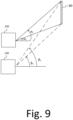
- Figure 9 provides an example of the controller 300 correlating the LIDAR data obtained from LIDAR 130 and video signal data obtained from the monocular camera 230, as an example of the plurality of cameras, when detecting the optical marker 80.
- Figure 9 shows the orientation of the optical marker 80 relative to the camera 230 and the LIDAR 130 in a two-dimensional space, however it would be understood that the orientation may be determined in a three-dimensional space instead.
- the two-dimensional space may correspond to a map of the industrial environment, and a three-dimensional space may include elevation(s) of different parts of the plan.
- the controller 300 may determine the optical marker 80 is located at a range of angle ⁇ 1 to ⁇ 2 , relative to the axis of capture of the camera 230. Then, based on the position of the camera 230 and the LIDAR 130 relative to each other, the controller 300 may determine the optical marker 80 corresponds to at a range of angle ⁇ 1 to ⁇ 2 for the LIDAR 130. The controller 300 can therefore determine that the LIDAR data includes a feature corresponding to the optical marker 80 if the LIDAR data includes at least one feature in the range of angle ⁇ 1 to ⁇ 2 . Using the LIDAR data, a second distance to the optical marker 80 may be estimated used to verify and/or adjust the first distance, which may be done using a process corresponding to the one described in connection with steps S708, S710 and S716.
- Software embodiments of the examples presented herein may be provided as, a computer program, or software, such as one or more programs having instructions or sequences of instructions, included or stored in an article of manufacture such as a machine-accessible or machine-readable medium, an instruction store, or computer-readable storage device, each of which can be non-transitory, in one example embodiment.
- the program or instructions on the non-transitory machine-accessible medium, machine-readable medium, instruction store, or computer-readable storage device may be used to program a computer system or other electronic device.
- the techniques described herein are not limited to any software configuration. They may find applicability in any computing or processing environment.
- computer-readable shall include any medium that is capable of storing, encoding, or transmitting instructions or a sequence of instructions for execution by the machine, computer, or computer processor and that causes the machine/computer/computer processor to perform any one of the methods described herein.
- Such expressions are merely a shorthand way of stating that the execution of the software by a processing system causes the processor to perform an action to produce a result.
Landscapes
- Engineering & Computer Science (AREA)
- Structural Engineering (AREA)
- Transportation (AREA)
- Aviation & Aerospace Engineering (AREA)
- Radar, Positioning & Navigation (AREA)
- Remote Sensing (AREA)
- Physics & Mathematics (AREA)
- General Physics & Mathematics (AREA)
- Automation & Control Theory (AREA)
- Geology (AREA)
- Mechanical Engineering (AREA)
- Life Sciences & Earth Sciences (AREA)
- Civil Engineering (AREA)
- Chemical & Material Sciences (AREA)
- Combustion & Propulsion (AREA)
- Control Of Position, Course, Altitude, Or Attitude Of Moving Bodies (AREA)
Applications Claiming Priority (1)
| Application Number | Priority Date | Filing Date | Title |
|---|---|---|---|
| IT102022000016311A IT202200016311A1 (it) | 2022-08-01 | 2022-08-01 | Guida autonoma o assistita di un carrello industriale utilizzando videocamere |
Publications (2)
| Publication Number | Publication Date |
|---|---|
| EP4318165A1 true EP4318165A1 (fr) | 2024-02-07 |
| EP4318165B1 EP4318165B1 (fr) | 2025-03-12 |
Family
ID=83439220
Family Applications (1)
| Application Number | Title | Priority Date | Filing Date |
|---|---|---|---|
| EP23188442.0A Active EP4318165B1 (fr) | 2022-08-01 | 2023-07-28 | Conduite autonome ou assistée de chariot de manutention à l'aide d'une pluralité de caméras |
Country Status (2)
| Country | Link |
|---|---|
| EP (1) | EP4318165B1 (fr) |
| IT (1) | IT202200016311A1 (fr) |
Cited By (2)
| Publication number | Priority date | Publication date | Assignee | Title |
|---|---|---|---|---|
| KR102858729B1 (ko) * | 2025-03-13 | 2025-09-12 | 주식회사 에이로보틱스 | Ai 카메라를 이용한 유인 지게차 안전 운전 지원 장치 |
| EP4632517A1 (fr) * | 2024-04-11 | 2025-10-15 | Airbus Operations GmbH | Système de navigation pour la navigation d'un robot mobile autonome dans un environnement de production |
Citations (3)
| Publication number | Priority date | Publication date | Assignee | Title |
|---|---|---|---|---|
| US20140277691A1 (en) * | 2013-03-15 | 2014-09-18 | Cybernet Systems Corporation | Automated warehousing using robotic forklifts |
| US10689194B2 (en) * | 2015-06-24 | 2020-06-23 | Hds Mercury, Inc. | Mobile robot loader-unloader system and method |
| WO2021170852A1 (fr) * | 2020-02-28 | 2021-09-02 | Tretyakov Slava | Procédé de commande d'un véhicule à guidage automatique et système de commande conçu pour exécuter le procédé |
-
2022
- 2022-08-01 IT IT102022000016311A patent/IT202200016311A1/it unknown
-
2023
- 2023-07-28 EP EP23188442.0A patent/EP4318165B1/fr active Active
Patent Citations (3)
| Publication number | Priority date | Publication date | Assignee | Title |
|---|---|---|---|---|
| US20140277691A1 (en) * | 2013-03-15 | 2014-09-18 | Cybernet Systems Corporation | Automated warehousing using robotic forklifts |
| US10689194B2 (en) * | 2015-06-24 | 2020-06-23 | Hds Mercury, Inc. | Mobile robot loader-unloader system and method |
| WO2021170852A1 (fr) * | 2020-02-28 | 2021-09-02 | Tretyakov Slava | Procédé de commande d'un véhicule à guidage automatique et système de commande conçu pour exécuter le procédé |
Cited By (2)
| Publication number | Priority date | Publication date | Assignee | Title |
|---|---|---|---|---|
| EP4632517A1 (fr) * | 2024-04-11 | 2025-10-15 | Airbus Operations GmbH | Système de navigation pour la navigation d'un robot mobile autonome dans un environnement de production |
| KR102858729B1 (ko) * | 2025-03-13 | 2025-09-12 | 주식회사 에이로보틱스 | Ai 카메라를 이용한 유인 지게차 안전 운전 지원 장치 |
Also Published As
| Publication number | Publication date |
|---|---|
| EP4318165B1 (fr) | 2025-03-12 |
| IT202200016311A1 (it) | 2024-02-01 |
Similar Documents
| Publication | Publication Date | Title |
|---|---|---|
| JP7082545B2 (ja) | 情報処理方法、情報処理装置およびプログラム | |
| EP3226026B1 (fr) | Système d'automatisation de déchargement pour décharger une récolte | |
| JP6464783B2 (ja) | 物体検出装置 | |
| CN104932515B (zh) | 一种自主巡航方法以及巡航设备 | |
| US9129523B2 (en) | Method and system for obstacle detection for vehicles using planar sensor data | |
| EP3904992B1 (fr) | Appareil de positionnement et corps mobile | |
| US12475592B2 (en) | Positioning apparatus capable of measuring position of moving body using image capturing apparatus | |
| US20180154901A1 (en) | Method and system for localizing a vehicle | |
| EP4318165A1 (fr) | Conduite autonome ou assistée de chariot de manutention à l'aide d'une pluralité de caméras | |
| EP3441906B1 (fr) | Appareil de traitement d'informations, objet mobile, procédé de traitement d'informations et support lisible sur ordinateur | |
| JP6447863B2 (ja) | 移動体 | |
| WO2019061311A1 (fr) | Procédé de commande d'une voiture autonome, terminal de commande et support d'informations lisible par machine | |
| KR20190045220A (ko) | 자기 위치 추정 방법 및 자기 위치 추정 장치 | |
| KR101747761B1 (ko) | 장해물 검출 장치 및 그것을 구비한 이동체 | |
| RU2740229C1 (ru) | Способ локализации и построения навигационных карт мобильного сервисного робота | |
| AU2020257038A1 (en) | Camera orientation estimation | |
| US20220113139A1 (en) | Object recognition device, object recognition method and program | |
| JP7486095B2 (ja) | 車両監視方法、車両監視装置、車両、及び車両監視システム | |
| JP2018048949A (ja) | 物体識別装置 | |
| KR20230018656A (ko) | 실내환경의 비전과 라이다를 융합한 slam 시스템 및 방법 | |
| JP2005258941A (ja) | 障害物検出装置 | |
| JP7179687B2 (ja) | 障害物検知装置 | |
| CN113125795A (zh) | 一种障碍物速度检测方法、装置、设备和存储介质 | |
| WO2023017624A1 (fr) | Dispositif d'entraînement, véhicule et procédé d'entraînement automatisé et/ou d'entraînement assisté | |
| JP6680502B2 (ja) | 移動体 |
Legal Events
| Date | Code | Title | Description |
|---|---|---|---|
| PUAI | Public reference made under article 153(3) epc to a published international application that has entered the european phase |
Free format text: ORIGINAL CODE: 0009012 |
|
| STAA | Information on the status of an ep patent application or granted ep patent |
Free format text: STATUS: THE APPLICATION HAS BEEN PUBLISHED |
|
| AK | Designated contracting states |
Kind code of ref document: A1 Designated state(s): AL AT BE BG CH CY CZ DE DK EE ES FI FR GB GR HR HU IE IS IT LI LT LU LV MC ME MK MT NL NO PL PT RO RS SE SI SK SM TR |
|
| STAA | Information on the status of an ep patent application or granted ep patent |
Free format text: STATUS: REQUEST FOR EXAMINATION WAS MADE |
|
| 17P | Request for examination filed |
Effective date: 20240726 |
|
| RBV | Designated contracting states (corrected) |
Designated state(s): AL AT BE BG CH CY CZ DE DK EE ES FI FR GB GR HR HU IE IS IT LI LT LU LV MC ME MK MT NL NO PL PT RO RS SE SI SK SM TR |
|
| REG | Reference to a national code |
Ref country code: DE Ref legal event code: R079 Free format text: PREVIOUS MAIN CLASS: G05D0001020000 Ipc: G05D0001000000 Ref country code: DE Ref legal event code: R079 Ref document number: 602023002387 Country of ref document: DE Free format text: PREVIOUS MAIN CLASS: G05D0001020000 Ipc: G05D0001000000 |
|
| GRAP | Despatch of communication of intention to grant a patent |
Free format text: ORIGINAL CODE: EPIDOSNIGR1 |
|
| STAA | Information on the status of an ep patent application or granted ep patent |
Free format text: STATUS: GRANT OF PATENT IS INTENDED |
|
| RIC1 | Information provided on ipc code assigned before grant |
Ipc: G05D 1/244 20240101ALI20240927BHEP Ipc: B66F 9/075 20060101ALI20240927BHEP Ipc: G05D 111/67 20240101ALI20240927BHEP Ipc: G05D 111/63 20240101ALI20240927BHEP Ipc: G05D 111/50 20240101ALI20240927BHEP Ipc: G05D 111/10 20240101ALI20240927BHEP Ipc: G05D 109/10 20240101ALI20240927BHEP Ipc: G05D 107/70 20240101ALI20240927BHEP Ipc: G05D 105/28 20240101ALI20240927BHEP Ipc: G05D 1/667 20240101ALI20240927BHEP Ipc: G05D 1/248 20240101ALI20240927BHEP Ipc: G05D 1/243 20240101ALI20240927BHEP Ipc: G05D 1/242 20240101ALI20240927BHEP Ipc: B66F 17/00 20060101ALI20240927BHEP Ipc: B66F 9/24 20060101ALI20240927BHEP Ipc: B66F 9/06 20060101ALI20240927BHEP Ipc: G05D 1/00 20240101AFI20240927BHEP |
|
| INTG | Intention to grant announced |
Effective date: 20241011 |
|
| GRAS | Grant fee paid |
Free format text: ORIGINAL CODE: EPIDOSNIGR3 |
|
| GRAA | (expected) grant |
Free format text: ORIGINAL CODE: 0009210 |
|
| STAA | Information on the status of an ep patent application or granted ep patent |
Free format text: STATUS: THE PATENT HAS BEEN GRANTED |
|
| AK | Designated contracting states |
Kind code of ref document: B1 Designated state(s): AL AT BE BG CH CY CZ DE DK EE ES FI FR GB GR HR HU IE IS IT LI LT LU LV MC ME MK MT NL NO PL PT RO RS SE SI SK SM TR |
|
| REG | Reference to a national code |
Ref country code: GB Ref legal event code: FG4D |
|
| REG | Reference to a national code |
Ref country code: CH Ref legal event code: EP |
|
| REG | Reference to a national code |
Ref country code: DE Ref legal event code: R096 Ref document number: 602023002387 Country of ref document: DE |
|
| REG | Reference to a national code |
Ref country code: IE Ref legal event code: FG4D |
|
| REG | Reference to a national code |
Ref country code: SE Ref legal event code: TRGR |
|
| PG25 | Lapsed in a contracting state [announced via postgrant information from national office to epo] |
Ref country code: RS Free format text: LAPSE BECAUSE OF FAILURE TO SUBMIT A TRANSLATION OF THE DESCRIPTION OR TO PAY THE FEE WITHIN THE PRESCRIBED TIME-LIMIT Effective date: 20250612 |
|
| PG25 | Lapsed in a contracting state [announced via postgrant information from national office to epo] |
Ref country code: FI Free format text: LAPSE BECAUSE OF FAILURE TO SUBMIT A TRANSLATION OF THE DESCRIPTION OR TO PAY THE FEE WITHIN THE PRESCRIBED TIME-LIMIT Effective date: 20250312 |
|
| PG25 | Lapsed in a contracting state [announced via postgrant information from national office to epo] |
Ref country code: ES Free format text: LAPSE BECAUSE OF FAILURE TO SUBMIT A TRANSLATION OF THE DESCRIPTION OR TO PAY THE FEE WITHIN THE PRESCRIBED TIME-LIMIT Effective date: 20250312 |
|
| REG | Reference to a national code |
Ref country code: LT Ref legal event code: MG9D |
|
| PG25 | Lapsed in a contracting state [announced via postgrant information from national office to epo] |
Ref country code: NO Free format text: LAPSE BECAUSE OF FAILURE TO SUBMIT A TRANSLATION OF THE DESCRIPTION OR TO PAY THE FEE WITHIN THE PRESCRIBED TIME-LIMIT Effective date: 20250612 |
|
| PG25 | Lapsed in a contracting state [announced via postgrant information from national office to epo] |
Ref country code: HR Free format text: LAPSE BECAUSE OF FAILURE TO SUBMIT A TRANSLATION OF THE DESCRIPTION OR TO PAY THE FEE WITHIN THE PRESCRIBED TIME-LIMIT Effective date: 20250312 |
|
| REG | Reference to a national code |
Ref country code: NL Ref legal event code: MP Effective date: 20250312 |
|
| PG25 | Lapsed in a contracting state [announced via postgrant information from national office to epo] |
Ref country code: LV Free format text: LAPSE BECAUSE OF FAILURE TO SUBMIT A TRANSLATION OF THE DESCRIPTION OR TO PAY THE FEE WITHIN THE PRESCRIBED TIME-LIMIT Effective date: 20250312 |
|
| PG25 | Lapsed in a contracting state [announced via postgrant information from national office to epo] |
Ref country code: GR Free format text: LAPSE BECAUSE OF FAILURE TO SUBMIT A TRANSLATION OF THE DESCRIPTION OR TO PAY THE FEE WITHIN THE PRESCRIBED TIME-LIMIT Effective date: 20250613 Ref country code: BG Free format text: LAPSE BECAUSE OF FAILURE TO SUBMIT A TRANSLATION OF THE DESCRIPTION OR TO PAY THE FEE WITHIN THE PRESCRIBED TIME-LIMIT Effective date: 20250312 |
|
| REG | Reference to a national code |
Ref country code: AT Ref legal event code: MK05 Ref document number: 1775515 Country of ref document: AT Kind code of ref document: T Effective date: 20250312 |
|
| PG25 | Lapsed in a contracting state [announced via postgrant information from national office to epo] |
Ref country code: NL Free format text: LAPSE BECAUSE OF FAILURE TO SUBMIT A TRANSLATION OF THE DESCRIPTION OR TO PAY THE FEE WITHIN THE PRESCRIBED TIME-LIMIT Effective date: 20250312 |
|
| PG25 | Lapsed in a contracting state [announced via postgrant information from national office to epo] |
Ref country code: SM Free format text: LAPSE BECAUSE OF FAILURE TO SUBMIT A TRANSLATION OF THE DESCRIPTION OR TO PAY THE FEE WITHIN THE PRESCRIBED TIME-LIMIT Effective date: 20250312 |
|
| PG25 | Lapsed in a contracting state [announced via postgrant information from national office to epo] |
Ref country code: PT Free format text: LAPSE BECAUSE OF FAILURE TO SUBMIT A TRANSLATION OF THE DESCRIPTION OR TO PAY THE FEE WITHIN THE PRESCRIBED TIME-LIMIT Effective date: 20250714 |
|
| PGFP | Annual fee paid to national office [announced via postgrant information from national office to epo] |
Ref country code: DE Payment date: 20250728 Year of fee payment: 3 |
|
| PG25 | Lapsed in a contracting state [announced via postgrant information from national office to epo] |
Ref country code: PL Free format text: LAPSE BECAUSE OF FAILURE TO SUBMIT A TRANSLATION OF THE DESCRIPTION OR TO PAY THE FEE WITHIN THE PRESCRIBED TIME-LIMIT Effective date: 20250312 |
|
| PGFP | Annual fee paid to national office [announced via postgrant information from national office to epo] |
Ref country code: IT Payment date: 20250731 Year of fee payment: 3 |
|
| PG25 | Lapsed in a contracting state [announced via postgrant information from national office to epo] |
Ref country code: AT Free format text: LAPSE BECAUSE OF FAILURE TO SUBMIT A TRANSLATION OF THE DESCRIPTION OR TO PAY THE FEE WITHIN THE PRESCRIBED TIME-LIMIT Effective date: 20250312 |
|
| PGFP | Annual fee paid to national office [announced via postgrant information from national office to epo] |
Ref country code: FR Payment date: 20250728 Year of fee payment: 3 |
|
| PGFP | Annual fee paid to national office [announced via postgrant information from national office to epo] |
Ref country code: SE Payment date: 20250731 Year of fee payment: 3 |
|
| PG25 | Lapsed in a contracting state [announced via postgrant information from national office to epo] |
Ref country code: EE Free format text: LAPSE BECAUSE OF FAILURE TO SUBMIT A TRANSLATION OF THE DESCRIPTION OR TO PAY THE FEE WITHIN THE PRESCRIBED TIME-LIMIT Effective date: 20250312 Ref country code: CZ Free format text: LAPSE BECAUSE OF FAILURE TO SUBMIT A TRANSLATION OF THE DESCRIPTION OR TO PAY THE FEE WITHIN THE PRESCRIBED TIME-LIMIT Effective date: 20250312 |
|
| PG25 | Lapsed in a contracting state [announced via postgrant information from national office to epo] |
Ref country code: RO Free format text: LAPSE BECAUSE OF FAILURE TO SUBMIT A TRANSLATION OF THE DESCRIPTION OR TO PAY THE FEE WITHIN THE PRESCRIBED TIME-LIMIT Effective date: 20250312 |
|
| PG25 | Lapsed in a contracting state [announced via postgrant information from national office to epo] |
Ref country code: SK Free format text: LAPSE BECAUSE OF FAILURE TO SUBMIT A TRANSLATION OF THE DESCRIPTION OR TO PAY THE FEE WITHIN THE PRESCRIBED TIME-LIMIT Effective date: 20250312 |
|
| PG25 | Lapsed in a contracting state [announced via postgrant information from national office to epo] |
Ref country code: IS Free format text: LAPSE BECAUSE OF FAILURE TO SUBMIT A TRANSLATION OF THE DESCRIPTION OR TO PAY THE FEE WITHIN THE PRESCRIBED TIME-LIMIT Effective date: 20250712 |
|
| REG | Reference to a national code |
Ref country code: DE Ref legal event code: R097 Ref document number: 602023002387 Country of ref document: DE |
|
| PG25 | Lapsed in a contracting state [announced via postgrant information from national office to epo] |
Ref country code: DK Free format text: LAPSE BECAUSE OF FAILURE TO SUBMIT A TRANSLATION OF THE DESCRIPTION OR TO PAY THE FEE WITHIN THE PRESCRIBED TIME-LIMIT Effective date: 20250312 |
|
| PLBE | No opposition filed within time limit |
Free format text: ORIGINAL CODE: 0009261 |
|
| STAA | Information on the status of an ep patent application or granted ep patent |
Free format text: STATUS: NO OPPOSITION FILED WITHIN TIME LIMIT |
|
| REG | Reference to a national code |
Ref country code: CH Ref legal event code: L10 Free format text: ST27 STATUS EVENT CODE: U-0-0-L10-L00 (AS PROVIDED BY THE NATIONAL OFFICE) Effective date: 20260121 |
|
| 26N | No opposition filed |
Effective date: 20251215 |
|
| PG25 | Lapsed in a contracting state [announced via postgrant information from national office to epo] |
Ref country code: LU Free format text: LAPSE BECAUSE OF NON-PAYMENT OF DUE FEES Effective date: 20250728 |
|
| REG | Reference to a national code |
Ref country code: BE Ref legal event code: MM Effective date: 20250731 |
|
| PG25 | Lapsed in a contracting state [announced via postgrant information from national office to epo] |
Ref country code: BE Free format text: LAPSE BECAUSE OF NON-PAYMENT OF DUE FEES Effective date: 20250731 |