EP4319030A2 - Conception de message de commande de liaison latérale nr - Google Patents
Conception de message de commande de liaison latérale nr Download PDFInfo
- Publication number
- EP4319030A2 EP4319030A2 EP23215059.9A EP23215059A EP4319030A2 EP 4319030 A2 EP4319030 A2 EP 4319030A2 EP 23215059 A EP23215059 A EP 23215059A EP 4319030 A2 EP4319030 A2 EP 4319030A2
- Authority
- EP
- European Patent Office
- Prior art keywords
- sidelink
- sidelink control
- control message
- message
- ues
- Prior art date
- Legal status (The legal status is an assumption and is not a legal conclusion. Google has not performed a legal analysis and makes no representation as to the accuracy of the status listed.)
- Pending
Links
Images








Classifications
-
- H—ELECTRICITY
- H04—ELECTRIC COMMUNICATION TECHNIQUE
- H04W—WIRELESS COMMUNICATION NETWORKS
- H04W72/00—Local resource management
- H04W72/20—Control channels or signalling for resource management
- H04W72/21—Control channels or signalling for resource management in the uplink direction of a wireless link, i.e. towards the network
-
- H—ELECTRICITY
- H04—ELECTRIC COMMUNICATION TECHNIQUE
- H04W—WIRELESS COMMUNICATION NETWORKS
- H04W72/00—Local resource management
- H04W72/02—Selection of wireless resources by user or terminal
-
- H—ELECTRICITY
- H04—ELECTRIC COMMUNICATION TECHNIQUE
- H04W—WIRELESS COMMUNICATION NETWORKS
- H04W72/00—Local resource management
- H04W72/20—Control channels or signalling for resource management
-
- H—ELECTRICITY
- H04—ELECTRIC COMMUNICATION TECHNIQUE
- H04W—WIRELESS COMMUNICATION NETWORKS
- H04W84/00—Network topologies
- H04W84/005—Moving wireless networks
-
- H—ELECTRICITY
- H04—ELECTRIC COMMUNICATION TECHNIQUE
- H04L—TRANSMISSION OF DIGITAL INFORMATION, e.g. TELEGRAPHIC COMMUNICATION
- H04L1/00—Arrangements for detecting or preventing errors in the information received
- H04L1/0001—Systems modifying transmission characteristics according to link quality, e.g. power backoff
- H04L1/0036—Systems modifying transmission characteristics according to link quality, e.g. power backoff arrangements specific to the receiver
- H04L1/0038—Blind format detection
-
- H—ELECTRICITY
- H04—ELECTRIC COMMUNICATION TECHNIQUE
- H04L—TRANSMISSION OF DIGITAL INFORMATION, e.g. TELEGRAPHIC COMMUNICATION
- H04L1/00—Arrangements for detecting or preventing errors in the information received
- H04L1/08—Arrangements for detecting or preventing errors in the information received by repeating transmission, e.g. Verdan system
-
- H—ELECTRICITY
- H04—ELECTRIC COMMUNICATION TECHNIQUE
- H04L—TRANSMISSION OF DIGITAL INFORMATION, e.g. TELEGRAPHIC COMMUNICATION
- H04L5/00—Arrangements affording multiple use of the transmission path
- H04L5/003—Arrangements for allocating sub-channels of the transmission path
- H04L5/0048—Allocation of pilot signals, i.e. of signals known to the receiver
-
- H—ELECTRICITY
- H04—ELECTRIC COMMUNICATION TECHNIQUE
- H04L—TRANSMISSION OF DIGITAL INFORMATION, e.g. TELEGRAPHIC COMMUNICATION
- H04L5/00—Arrangements affording multiple use of the transmission path
- H04L5/003—Arrangements for allocating sub-channels of the transmission path
- H04L5/0053—Allocation of signalling, i.e. of overhead other than pilot signals
-
- H—ELECTRICITY
- H04—ELECTRIC COMMUNICATION TECHNIQUE
- H04W—WIRELESS COMMUNICATION NETWORKS
- H04W4/00—Services specially adapted for wireless communication networks; Facilities therefor
- H04W4/06—Selective distribution of broadcast services, e.g. multimedia broadcast multicast service [MBMS]; Services to user groups; One-way selective calling services
- H04W4/08—User group management
-
- H—ELECTRICITY
- H04—ELECTRIC COMMUNICATION TECHNIQUE
- H04W—WIRELESS COMMUNICATION NETWORKS
- H04W4/00—Services specially adapted for wireless communication networks; Facilities therefor
- H04W4/30—Services specially adapted for particular environments, situations or purposes
- H04W4/40—Services specially adapted for particular environments, situations or purposes for vehicles, e.g. vehicle-to-pedestrians [V2P]
-
- H—ELECTRICITY
- H04—ELECTRIC COMMUNICATION TECHNIQUE
- H04W—WIRELESS COMMUNICATION NETWORKS
- H04W48/00—Access restriction; Network selection; Access point selection
- H04W48/08—Access restriction or access information delivery, e.g. discovery data delivery
- H04W48/10—Access restriction or access information delivery, e.g. discovery data delivery using broadcasted information
-
- H—ELECTRICITY
- H04—ELECTRIC COMMUNICATION TECHNIQUE
- H04W—WIRELESS COMMUNICATION NETWORKS
- H04W72/00—Local resource management
- H04W72/04—Wireless resource allocation
- H04W72/044—Wireless resource allocation based on the type of the allocated resource
- H04W72/0446—Resources in time domain, e.g. slots or frames
-
- H—ELECTRICITY
- H04—ELECTRIC COMMUNICATION TECHNIQUE
- H04W—WIRELESS COMMUNICATION NETWORKS
- H04W72/00—Local resource management
- H04W72/04—Wireless resource allocation
- H04W72/044—Wireless resource allocation based on the type of the allocated resource
- H04W72/0453—Resources in frequency domain, e.g. a carrier in FDMA
-
- H—ELECTRICITY
- H04—ELECTRIC COMMUNICATION TECHNIQUE
- H04W—WIRELESS COMMUNICATION NETWORKS
- H04W72/00—Local resource management
- H04W72/04—Wireless resource allocation
- H04W72/044—Wireless resource allocation based on the type of the allocated resource
- H04W72/046—Wireless resource allocation based on the type of the allocated resource the resource being in the space domain, e.g. beams
-
- H—ELECTRICITY
- H04—ELECTRIC COMMUNICATION TECHNIQUE
- H04W—WIRELESS COMMUNICATION NETWORKS
- H04W72/00—Local resource management
- H04W72/20—Control channels or signalling for resource management
- H04W72/23—Control channels or signalling for resource management in the downlink direction of a wireless link, i.e. towards a terminal
-
- H—ELECTRICITY
- H04—ELECTRIC COMMUNICATION TECHNIQUE
- H04W—WIRELESS COMMUNICATION NETWORKS
- H04W76/00—Connection management
- H04W76/10—Connection setup
- H04W76/14—Direct-mode setup
-
- H—ELECTRICITY
- H04—ELECTRIC COMMUNICATION TECHNIQUE
- H04L—TRANSMISSION OF DIGITAL INFORMATION, e.g. TELEGRAPHIC COMMUNICATION
- H04L1/00—Arrangements for detecting or preventing errors in the information received
- H04L1/0001—Systems modifying transmission characteristics according to link quality, e.g. power backoff
- H04L1/0036—Systems modifying transmission characteristics according to link quality, e.g. power backoff arrangements specific to the receiver
- H04L1/0039—Systems modifying transmission characteristics according to link quality, e.g. power backoff arrangements specific to the receiver other detection of signalling, e.g. detection of TFCI explicit signalling
-
- H—ELECTRICITY
- H04—ELECTRIC COMMUNICATION TECHNIQUE
- H04L—TRANSMISSION OF DIGITAL INFORMATION, e.g. TELEGRAPHIC COMMUNICATION
- H04L1/00—Arrangements for detecting or preventing errors in the information received
- H04L1/004—Arrangements for detecting or preventing errors in the information received by using forward error control
- H04L1/0041—Arrangements at the transmitter end
-
- H—ELECTRICITY
- H04—ELECTRIC COMMUNICATION TECHNIQUE
- H04L—TRANSMISSION OF DIGITAL INFORMATION, e.g. TELEGRAPHIC COMMUNICATION
- H04L1/00—Arrangements for detecting or preventing errors in the information received
- H04L1/004—Arrangements for detecting or preventing errors in the information received by using forward error control
- H04L1/0045—Arrangements at the receiver end
-
- H—ELECTRICITY
- H04—ELECTRIC COMMUNICATION TECHNIQUE
- H04L—TRANSMISSION OF DIGITAL INFORMATION, e.g. TELEGRAPHIC COMMUNICATION
- H04L1/00—Arrangements for detecting or preventing errors in the information received
- H04L1/12—Arrangements for detecting or preventing errors in the information received by using return channel
- H04L1/16—Arrangements for detecting or preventing errors in the information received by using return channel in which the return channel carries supervisory signals, e.g. repetition request signals
- H04L1/18—Automatic repetition systems, e.g. Van Duuren systems
-
- H—ELECTRICITY
- H04—ELECTRIC COMMUNICATION TECHNIQUE
- H04L—TRANSMISSION OF DIGITAL INFORMATION, e.g. TELEGRAPHIC COMMUNICATION
- H04L5/00—Arrangements affording multiple use of the transmission path
- H04L5/0001—Arrangements for dividing the transmission path
- H04L5/0003—Two-dimensional division
- H04L5/0005—Time-frequency
- H04L5/0007—Time-frequency the frequencies being orthogonal, e.g. OFDM(A) or DMT
- H04L5/001—Time-frequency the frequencies being orthogonal, e.g. OFDM(A) or DMT the frequencies being arranged in component carriers
Definitions
- the present application concerns the field of wireless communication systems and networks, more specifically the direct communication among network entities, like user devices, in such wireless communication systems or networks using a sidelink communication.
- Embodiments of the present invention concern improvements/enhancements of a two-stage SCI, sidelink control information.
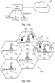
- Fig. 1 is a schematic representation of an example of a terrestrial wireless network 100 including, as is shown in Fig. 1(a) , a core network 102 and one or more radio access networks RAN 1 , RAN 2 , ...RAN N .
- Fig. 1(b) is a schematic representation of an example of a radio access network RAN n that may include one or more base stations gNB 1 to gNB 5 , each serving a specific area surrounding the base station schematically represented by respective cells 106 1 to 106 5 .
- the base stations are provided to serve users within a cell.
- base station refers to a gNB in 5G networks, an eNB in UMTS/LTE/LTE-A/ LTE-A Pro, or just a BS in other mobile communication standards.
- a user may be a stationary device or a mobile device.
- the wireless communication system may also be accessed by mobile or stationary loT devices which connect to a base station or to a user.
- the mobile devices or the loT devices may include physical devices, ground based vehicles, such as robots or cars, aerial vehicles, such as manned or unmanned aerial vehicles (UAVs), the latter also referred to as drones, buildings and other items or devices having embedded therein electronics, software, sensors, actuators, or the like as well as network connectivity that enables these devices to collect and exchange data across an existing network infrastructure.
- Fig. 1(b) shows an exemplary view of five cells, however, the RAN n may include more or less such cells, and RAN n may also include only one base station.
- Fig. 1(b) shows two users UE 1 and UE 2 , also referred to as user equipment, UE, that are in cell 106 2 and that are served by base station gNB 2 .
- FIG. 1(b) shows two loT devices 110 1 and 110 2 in cell 106 4 , which may be stationary or mobile devices.
- the loT device 110 1 accesses the wireless communication system via the base station gNB 4 to receive and transmit data as schematically represented by arrow 112 1 .
- the loT device 110 2 accesses the wireless communication system via the user UE 3 as is schematically represented by arrow 112 2 .
- the respective base station gNB 1 to gNB 5 may be connected to the core network 102, e.g. via the S1 interface, via respective backhaul links 114 1 to 114 5 , which are schematically represented in Fig. 1(b) by the arrows pointing to "core”.
- the core network 102 may be connected to one or more external networks. Further, some or all of the respective base station gNB 1 to gNB 5 may connected, e.g. via the S1 or X2 interface or the XN interface in NR, with each other via respective backhaul links 116 1 to 116 5 , which are schematically represented in Fig. 1(b) by the arrows pointing to "gNBs".
- the physical resource grid may comprise a set of resource elements to which various physical channels and physical signals are mapped.
- the physical channels may include the physical downlink, uplink and sidelink shared channels (PDSCH, PUSCH, PSSCH) carrying user specific data, also referred to as downlink, uplink and sidelink payload data, the physical broadcast channel (PBCH) carrying for example a master information block (MIB) and a system information block (SIB), the physical downlink, uplink and sidelink control channels (PDCCH, PUCCH, PSSCH) carrying for example the downlink control information (DCI), the uplink control information (UCI) and the sidelink control information (SCI).
- PBCH physical broadcast channel
- MIB master information block
- SIB system information block
- PDCCH, PUCCH, PSSCH carrying for example the downlink control information (DCI), the uplink control information (UCI) and the sidelink control information (SCI).
- DCI downlink control information
- UCI uplink control information
- SCI sidelink control information
- the physical channels may further include the physical random access channel (PRACH or RACH) used by UEs for accessing the network once a UE synchronized and obtained the MIB and SIB.
- the physical signals may comprise reference signals or symbols (RS), synchronization signals and the like.
- the resource grid may comprise a frame or radio frame having a certain duration in the time domain and having a given bandwidth in the frequency domain.
- the frame may have a certain number of subframes of a predefined length, e.g. 1ms. Each subframe may include one or more slots of 12 or 14 OFDM symbols depending on the cyclic prefix (CP) length.
- a frame may also consist of a smaller number of OFDM symbols, e.g. when utilizing shortened transmission time intervals (sTTI) or a mini-slot/non-slot-based frame structure comprising just a few OFDM symbols.
- sTTI shortened transmission time intervals
- mini-slot/non-slot-based frame structure comprising just
- the wireless communication system may be any single-tone or multicarrier system using frequency-division multiplexing, like the orthogonal frequency-division multiplexing (OFDM) system, the orthogonal frequency-division multiple access (OFDMA) system, or any other IFFT-based signal with or without CP, e.g. DFT-s-OFDM.
- Other waveforms like non-orthogonal waveforms for multiple access, e.g. filter-bank multicarrier (FBMC), generalized frequency division multiplexing (GFDM) or universal filtered multi carrier (UFMC), may be used.
- FBMC filter-bank multicarrier
- GFDM generalized frequency division multiplexing
- UFMC universal filtered multi carrier
- the wireless communication system may operate, e.g., in accordance with the LTE-Advanced pro standard or the 5G or NR, New Radio, standard.
- the wireless network or communication system depicted in Fig. 1 may by a heterogeneous network having distinct overlaid networks, e.g., a network of macro cells with each macro cell including a macro base station, like base station gNB 1 to gNB 5 , and a network of small cell base stations (not shown in Fig. 1 ), like femto or pico base stations.
- a network of macro cells with each macro cell including a macro base station, like base station gNB 1 to gNB 5 , and a network of small cell base stations (not shown in Fig. 1 ), like femto or pico base stations.
- non-terrestrial wireless communication networks including spaceborne transceivers, like satellites, and/or airborne transceivers, like unmanned aircraft systems.
- the non-terrestrial wireless communication network or system may operate in a similar way as the terrestrial system described above with reference to Fig. 1 , for example in accordance with the LTE-Advanced Pro standard or the 5G or NR, new radio, standard.
- UEs that communicate directly with each other over one or more sidelink (SL) channels e.g., using the PC5 interface.
- UEs that communicate directly with each other over the sidelink may include vehicles communicating directly with other vehicles (V2V communication), vehicles communicating with other entities of the wireless communication network (V2X communication), for example roadside entities, like traffic lights, traffic signs, or pedestrians.
- V2V communication vehicles communicating directly with other vehicles
- V2X communication vehicles communicating with other entities of the wireless communication network
- Other UEs may not be vehicular related UEs and may comprise any of the above-mentioned devices.
- Such devices may also communicate directly with each other (D2D communication) using the SL channels.
- both UEs When considering two UEs directly communicating with each other over the sidelink, both UEs may be served by the same base station so that the base station may provide sidelink resource allocation configuration or assistance for the UEs. For example, both UEs may be within the coverage area of a base station, like one of the base stations depicted in Fig. 1 . This is referred to as an "in-coverage” scenario. Another scenario is referred to as an "out-of-coverage” scenario. It is noted that "out-of-coverage” does not mean that the two UEs are not within one of the cells depicted in Fig. 1 , rather, it means that these UEs
- one of the UEs may also be connected with a BS, and may relay information from the BS to the other UE via the sidelink interface.
- the relaying may be performed in the same frequency band (in-band-relay) or another frequency band (out-of-band relay) may be used.
- communication on the Uu and on the sidelink may be decoupled using different time slots as in time division duplex, TDD, systems.
- Fig. 2 is a schematic representation of an in-coverage scenario in which two UEs directly communicating with each other are both connected to a base station.
- the base station gNB has a coverage area that is schematically represented by the circle 200 which, basically, corresponds to the cell schematically represented in Fig. 1 .
- the UEs directly communicating with each other include a first vehicle 202 and a second vehicle 204 both in the coverage area 200 of the base station gNB. Both vehicles 202, 204 are connected to the base station gNB and, in addition, they are connected directly with each other over the PC5 interface.
- the scheduling and/or interference management of the V2V traffic is assisted by the gNB via control signaling over the Uu interface, which is the radio interface between the base station and the UEs.
- the gNB provides SL resource allocation configuration or assistance for the UEs, and the gNB assigns the resources to be used for the V2V communication over the sidelink.
- This configuration is also referred to as a mode 1 configuration in NR V2X or as a mode 3 configuration in LTE V2X.
- Fig. 3 is a schematic representation of an out-of-coverage scenario in which the UEs directly communicating with each other are either not connected to a base station, although they may be physically within a cell of a wireless communication network, or some or all of the UEs directly communicating with each other are to a base station but the base station does not provide for the SL resource allocation configuration or assistance.
- Three vehicles 206, 208 and 210 are shown directly communicating with each other over a sidelink, e.g., using the PC5 interface.
- the scheduling and/or interference management of the V2V traffic is based on algorithms implemented between the vehicles. This configuration is also referred to as a mode 2 configuration in NR V2X or as a mode 4 configuration in LTE V2X.
- the scenario in Fig. 3 which is the out-of-coverage scenario does not necessarily mean that the respective mode 2 UEs (in NR) or mode 4 UEs (in LTE) are outside of the coverage 200 of a base station, rather, it means that the respective mode 2 UEs (in NR) or mode 4 UEs (in LTE) are not served by a base station, are not connected to the base station of the coverage area, or are connected to the base station but receive no SL resource allocation configuration or assistance from the base station.
- a plurality of such user devices may form a user device group, also referred to simply as group, and the communication within the group or among the group members may be performed via the sidelink interfaces between the user devices, like the PC5 interface.
- the above-described scenarios using vehicular user devices may be employed in the field of the transport industry in which a plurality of vehicles being equipped with vehicular user devices may be grouped together, for example, by a remote driving application.
- Other use cases in which a plurality of user devices may be grouped together for a sidelink communication among each other include, for example, factory automation and electrical power distribution.
- a plurality of mobile or stationary machines within a factory may be equipped with user devices and grouped together for a sidelink communication, for example for controlling the operation of the machine, like a motion control of a robot.
- entities within the power distribution grid may be equipped with respective user devices which, within a certain area of the system may be grouped together so as to communicate via a sidelink communication with each other so as to allow for monitoring the system and for dealing with power distribution grid failures and outages.
- sidelink communication is not limited to a communication within a group. Rather, the sidelink communication may be among any of UEs, like any pair of UEs.
- a sidelink communication among respective network entities may be performed, and such a sidelink communication includes the transmission of control information using respective sidelink control messages, also referred to as sidelink control information, SCI.
- SCI in LTE contains information about the time-frequency resources to be used for a data transmission, also referred to as a PSSCH transmission.
- the resource blocks or the resource pools are specified, i.e., the set of resources on which the PSSCH is transmitted.
- the SCI is transmitted in the PSCCH, for example, with every PSSCH.
- the LTE SCI may include, in addition to the above-mentioned time-frequency resources one or more of the following information:
- the SCI provides the necessary control information for the sidelink, SL, transmission.
- the SCI is carried by the PSCCH and enables the receiving sidelink UE to properly detect and decode the data transmission on the PSSCH, and to extract the data from the SL-SCH, namely from the transport channel, also referred to as to the SL shared channel.
- direct communications among user devices are enabled, for example, V2X communications, so that NR also provides for SCI on a physical layer, and, in addition, NR supports unicast and groupcast communications on the sidelink communication, in addition to a broadcast communication, which is the only SL communication allowed in LTE.
- the SCI may be split into several parts, for example, into a first part and into a second part, and such a split SCI is also referred to as a two-stage SCI.
- the first part of the first stage of the SCI may be decoded, for example, by all sidelink UEs, and the second part or the second stage may be decoded by the sidelink UEs for which the current communication or transmission is intended or which are addressed by the current SL communication.
- the two-stage SCI may have advantages over a single-stage SCI.
- the efficiency may decrease, especially for broadcast communications, as some padding information is to be added.
- the two-stage SCI may be advantageous because the first part or first stage may be used for providing some or more essential information for the sidelink communication, and the second stage or second part of the SCI includes detailed information for decoding the data channel, for example the PSSCH that is decoded in case the SCI is actually intended for a UE that identified the first part of the SCI.
- the SCI sizes may differ which may lead to an increase in the decoding process time when decoding the first part or first stage of the SCI.
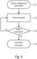
- Fig. 4 illustrates a flow diagram of a first stage SCI blind decoding process.
- the UE that is to participate in a sidelink communication, may receive certain configuration parameters for the sidelink communication.
- the UE which in the context of the SL communication may be referred to as to the receiving UE, starts blind decoding, as is indicated at S2 on the first part of the SCI.
- the receiving UE performs a decoding procedure for decoding information from the first stage or first part SCI.
- the above-described two-step decoding algorithm may be employed where, initially, the first part of the SCI, for example, the format type, may be identified by means of blind decoding, for example based on different DMRS patterns (see S2, S3 in Fig. 4 ). Then, at a second stage (see S4 in Fig. 4 above) a normal decoding may be applied to derive the information embedded in the first part of the SCI that has been identified at the first step.
- the SCI may be indicated to the receiving UE as being a two-stage SCI using a certain parameter, for example the parameter cdm-type which may be configured using an RRC configuration or reconfiguration message in case the receiving UE is in the connected mode, or by a system information block, SIB, for example in case the receiving UE is in the idle mode.
- a certain parameter for example the parameter cdm-type which may be configured using an RRC configuration or reconfiguration message in case the receiving UE is in the connected mode, or by a system information block, SIB, for example in case the receiving UE is in the idle mode.
- the present invention provides approaches for improving the SCI design, both the single stage SCI and the two-stage SCI design, so as to provide, for example, improvements, for example, in terms of flexibility, complexity, forward compatibility, overhead, latency, robustness, reliability.
- Embodiments of the present invention may be implemented in a wireless communication system as depicted in Fig. 1 , Fig. 2, and Fig. 3 including base stations and users, like mobile terminals or loT devices.
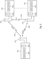
- Fig. 5 is a schematic representation of a wireless communication system including a transmitter 300, like a base station, and one or more receivers 302 1 to 302 n , like user devices, UEs.
- the transmitter 300 and the receivers 302 may communicate via one or more wireless communication links or channels 304a, 304b, 304c, like a radio link.
- the transmitter 300 may include one or more antennas ANT T or an antenna array having a plurality of antenna elements, a signal processor 300a and a transceiver 300b, coupled with each other.
- the receivers 302 include one or more antennas ANT R or an antenna array having a plurality of antennas, a signal processor 302a 1 , 302a n , and a transceiver 302b 1 , 302b n coupled with each other.
- the base station 300 and the UEs 302 may communicate via respective first wireless communication links 304a and 304b, like a radio link using the Uu interface, while the UEs 302 may communicate with each other via a second wireless communication link 304c, like a radio link using the PC5 interface.
- the UEs When the UEs are not served by the base station, are not be connected to a base station, for example, they are not in an RRC connected state, or, more generally, when no SL resource allocation configuration or assistance is provided by a base station, the UEs may communicate with each other over the sidelink.
- the system, the one or more UEs and the base stations may operate in accordance with the inventive teachings described herein.
- the present invention provides a user device, UE, for a wireless communication system, wherein
- the SL search space includes one or more of a UE-common SL search space and a UE-specific SL search space.
- the UE is to receive
- the UE-common SL search space identifies one or more of:
- the UE-common SL search space identifies one or more of:
- the UE-specific SL search space identifies one or more of:
- the UE-specific SL search space identifies one or more of:
- the UE-specific SL search space identifies a search space signaled by a transmitting UE to be used by the receiving UE or a group of receiving UEs, e.g., using a physical, L1, SL control channel, or an in-data control channel, or an SL-RRC control message.
- the SL search space defines a number of symbols in time, e.g., NsymbSL-CORSET, and a number of resource blocks, RBs, e.g., NRBSL-CORSET, and a location of the resources blocks within the sidelink resources, like a resource pool or a SL-bandwidth part, SL-BWP.
- the sidelink control message includes at least a first part, e.g., a first stage, and a second part, e.g. a second stage, and wherein the sidelink search space includes one or more search occasions where the UE is to perform the blind decoding for identifying the first part of the sidelink control message.
- the present invention provides a network entity for a wireless communication system, the wireless communication including one or more UEs to be connected to one or more further UEs for a sidelink communication with the one or more further UEs, the sidelink communication including one or more sidelink control messages, e.g., Sidelink Control Information, SCI, to be transmitted on sidelink resources, wherein the network entity is to signal to a receiving UE or a group of receiving UEs a UE-specific SL search space, e.g., a SL-CORESET, in the sidelink resources, so as to indicate to the receiving UE one or more search occasions where the receiving UE is to perform blind decoding on the sidelink resources for identifying a sidelink control message for the receiving UE, e.g., a Sidelink Control Information, SCI.
- SCI Sidelink Control Information
- the network entity is a transmitting user device, UE, and wherein, once a SL communication using the UE-specific SL search space with a receiving UE is completed or interrupted, the transmitting UE is to employ a UE-common SL-search space.
- the present invention provides a user device, UE, for a wireless communication system, wherein
- the information embedded in the sidelink control message indicates time and frequency resources for the further message.
- the time and frequency resources for the sidelink control message and the time and frequency resources for the further message are one or more of
- the information embedded in the sidelink control message indicates one or more of
- the information embedded in the sidelink control message indicates a periodicity of transmissions of the of the sidelink message and/or the further message.
- a predefined value for the periodicity may be provided to signal either a single shot transmission of the sidelink control message and/or the further message without any periodicity or a release of a previous periodicity.
- the information embedded in the first part of the sidelink control message indicates one or more of:
- the sidelink control message includes a first part of the control information, e.g., a first stage SCI, and the further message includes at least a second part of the control information, e.g. a second stage SCI, and/or one or more transmission reservations for the data.
- the present invention provides a network entity for a wireless communication system, the wireless communication including one or more UEs to be connected to one or more further UEs for a sidelink communication with the one or more further UEs, the sidelink communication including one or more sidelink control messages, e.g., Sidelink Control Information, SCI, to be transmitted on sidelink resources, wherein the network entity is to signal to a receiving UE or a group of receiving UEs a sidelink control message, wherein information embedded in the sidelink control message indicates a configuration of a further message, the further message including further control information and/or data.
- SCI Sidelink Control Information
- the present invention provides a user device, UE, for a wireless communication system, wherein
- the present invention provides a network entity for a wireless communication system, the wireless communication including one or more UEs to be connected to one or more further UEs for a sidelink communication with the one or more further UEs, the sidelink communication including one or more sidelink control messages, e.g., Sidelink Control Information, SCI, to be transmitted on sidelink resources, a sidelink control message including at least a first part, e.g., a first stage, and a second part, e.g. a second stage, wherein the network entity is to signal to a receiving UE or a group of receiving UEs in or together with the first part of the sidelink control message a reference signal, e.g., a certain demodulation reference signal, DMRS.
- a reference signal e.g., a certain demodulation reference signal, DMRS.
- the reference signal has a pattern associated with a certain cast type of the second part of the sidelink control message.
- the reference signal has a pattern associated with certain use-cases with certain QoS of the second part of the sidelink control message.
- the reference signal is selected from a plurality of reference signals having pattern being different from each other in one or more of
- some or all of the plurality of reference signals have a unique design, e.g., orthogonal or quasi-orthogonal DMRS patterns, to protect the UE from collisions.
- the reference signal is a DMRS having a DMRS type 1 configuration.
- the first part of the sidelink control message is accompanied by a plurality of reference signals, e.g., certain DMRS patterns.
- the same or different reference signals are repeated over the time domain, so as to be
- a repetition rate of reference signals depends on a velocity with which the UE moves, e.g., the repetition rate may be higher when the UE moves with a first speed, and the repetition rate may be lower when the UE moves with a second speed, the first speed being higher than the second speed.
- the present invention provides a user device, UE, for a wireless communication system, wherein
- the UE is not to expect, e.g., is not to read or is not to decode, the second part of the sidelink control message in case the first part of the sidelink control message includes
- the first part of the sidelink control message includes a broadcast ID and a UE or group ID
- the UE is to expect, e.g., is to read or is to decode, the second part of the sidelink control message in case the first part of the sidelink control message includes
- the sidelink control message may be scrambled, e.g., using CRC scrambling, with a UE ID or a group ID or a broadcast ID,
- the UE is to implicitly derive a cast type from a UE ID or a group ID or a broadcast ID or an absence of any ID in the first part of the sidelink control message as follows:
- the UE is not to expect, e.g., is not to read or is not to decode, a second part of the sidelink control message in case the first part of the sidelink control message includes a broadcast ID indicating a broadcast type of communication, e.g., in case of a single-stage broadcast.
- the UE is to determine whether the sidelink control message is intended for the UE from a source ID in the first part of the sidelink control message, the source ID being a source ID of an originator of a unicast communication or of an originator of the groupcast communication.
- the present invention provides a network entity for a wireless communication system, the wireless communication including one or more UEs to be connected to one or more further UEs for a sidelink communication with the one or more further UEs, the sidelink communication including one or more sidelink control messages, e.g., Sidelink Control Information, SCI, to be transmitted on sidelink resources, a sidelink control message including at least a first part, e.g., a first stage, and a second part, e.g. a second stage, wherein the network entity is to indicate in the first part of the sidelink control message whether the sidelink control message is intended for a receiving UE.
- sidelink control messages e.g., Sidelink Control Information, SCI
- the UE is to derive from the information in the first part of the sidelink control message whether the sidelink control message is intended for the UE.
- the present invention provides a wireless communication system comprising an inventive user device or an inventive network entity.
- the wireless communication system comprises one or more base stations, wherein the base station comprises one or more of a macro cell base station, or a small cell base station, or a central unit of a base station, or a distributed unit of a base station, or a road side unit, or a UE, or a remote radio head, or an AMF, or an SMF, or a core network entity, or a network slice as in the NR or 5G core context, or any transmission/reception point, TRP, enabling an item or a device to communicate using the wireless communication network, the item or device being provided with network connectivity to communicate using the wireless communication network.
- the base station comprises one or more of a macro cell base station, or a small cell base station, or a central unit of a base station, or a distributed unit of a base station, or a road side unit, or a UE, or a remote radio head, or an AMF, or an SMF, or a core network entity, or a network slice as in the NR or 5G core context
- the present invention provides a method for a wireless communication system, the method comprising:
- the present invention provides a method for a wireless communication system, the wireless communication including one or more UEs to be connected to one or more further UEs for a sidelink communication with the one or more further UEs, the sidelink communication including one or more sidelink control messages, e.g., Sidelink Control Information, SCI, to be transmitted on sidelink resources, the method comprising: signaling, by a network entity, to a receiving UE or a group of receiving UEs a UE-specific SL search space, e.g., a SL-CORESET, in the sidelink resources, so as to indicate to the receiving UE one or more search occasions where the receiving UE is to perform blind decoding on the sidelink resources for identifying a sidelink control message for the receiving UE, e.g., a Sidelink Control Information, SCI.
- SCI Sidelink Control Information
- the present invention provides a method for a wireless communication system, the method comprising
- the present invention provides a method for a wireless communication system, the wireless communication including one or more UEs to be connected to one or more further UEs for a sidelink communication with the one or more further UEs, the sidelink communication including one or more sidelink control messages, e.g., Sidelink Control Information, SCI, to be transmitted on sidelink resources, the method comprising: signaling, by a network entity, to a receiving UE or a group of receiving UEs a sidelink control message, wherein information embedded in the sidelink control message indicates a configuration of a further message, the further message including further control information and/or data.
- SCI Sidelink Control Information
- the present invention provides a method for a wireless communication system, the method comprising
- the present invention provides a method for a wireless communication system, the wireless communication including one or more UEs to be connected to one or more further UEs for a sidelink communication with the one or more further UEs, the sidelink communication including one or more sidelink control messages, e.g., Sidelink Control Information, SCI, to be transmitted on sidelink resources, a sidelink control message including at least a first part, e.g., a first stage, and a second part, e.g.
- SCI Sidelink Control Information
- a second stage comprising: signaling, by a network entity, to a receiving UE or a group of receiving UEs in or together with the first part of the sidelink control message a reference signal, e.g., a certain demodulation reference signal, DMRS.
- a reference signal e.g., a certain demodulation reference signal, DMRS.
- the present invention provides a method for a wireless communication system, the method comprising
- the present invention provides a method for a wireless communication system, the wireless communication including one or more UEs to be connected to one or more further UEs for a sidelink communication with the one or more further UEs, the sidelink communication including one or more sidelink control messages, e.g., Sidelink Control Information, SCI, to be transmitted on sidelink resources, a sidelink control message including at least a first part, e.g., a first stage, and a second part, e.g. a second stage, the method comprising: indicating, by the network entity, in the first part of the sidelink control message whether the sidelink control message is intended for a receiving UE.
- sidelink control messages e.g., Sidelink Control Information, SCI
- the present invention provides a computer program product comprising instructions which, when the program is executed by a computer, causes the computer to carry out one or more methods in accordance with the present invention.
- Embodiments of the present invention provide for improvements and enhancements of a single-stage or a two-stage sidelink control message, like a two-stage SCI, as it may be employed in NR sidelink communications, like V2X communications or the like.
- NR sidelink communications like V2X communications or the like.
- aspects of the present invention are described which provide for enhancements with regard to the flexibility, complexity, forward compatibility, overhead, specification impact, latency, robustness and.
- the subsequently described aspects may be used independently from each other or some or all of the aspects may be combined. Further, when referring in the following description to a first part of the sidelink control information or to a first stage SCI, this may simply refer to
- a search space may be configured so as to indicate to a UE participating in a sidelink communication the search occasions to perform blind decoding so as to identify a first part of a two-stage SCI as indicated at S2 in Fig. 4 above.
- certain resources may be allocated to a sidelink communication, which are also referred as resource sets or resource pools.
- Some of the sidelink resources may be used for control purposes, and respective sidelink control resource sets, SL-CORESETs, may be identified, and within such a SL-CORESET one or more search spaces for a receiving UE may be identified.
- the search space may be configured for all UEs or for a group of UEs using a broadcast message, for example the system information block, SIB, or a group common control channel.
- a receiving UE may receive the signaling indicating a specific search space that is to be used by the receiving UE for the blind decoding from a transmitting UE, using, for example, a dedicated radio resource control, RRC, message.
- RRC radio resource control
- a UE participating in a sidelink communication may be pre-configured with the search space using a pre-configuration message.
- the search space may be used for one, some or all UEs on common SL frequency resources, for example in selected sub-channels or PRBs, in selected resource pools, or a common bandwidth part, BWP.
- a search space also referred to as a modified search space, may be signaled by one UE, for example a transmitting UE in the sidelink communication pair, to be used by one or more other UEs or by a group of UEs.
- a transmitting UE, performing a unicast or groupcast communication may signal its specific search space in a physical, L1, SL control channel, or in an in-data control channel, or in a SL-RRC control message.
- the search space also referred to as to the first stage search space, the sidelink search space, or the SL space, contains the search occasions where a sidelink receiver UE performs decoding, like blind decoding, on the configured sidelink control resources or the sidelink control resource set, SL-CORESET.
- the SL-CORESET may define a number of symbols in time, e.g., N symb SL ⁇ CORESET , and a number of resource blocks, RBs, for example N RB SL ⁇ CORESET , as well as a location of the resource blocks within the resource pool or within a SL-bandwidth part, SL-BWP, for example, by defining the N_sub-channels-index.
- the SL-CORESET may be configured for all UEs in a common search space message which may be conveyed in an RRC broadcast message, for example in a system information block, SIB, message, like SIB18, SIB19, SIB20 and SIB26.
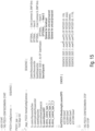
- Fig. 6 illustrates an embodiment of a SL-search space information element that may be used for configuring sidelink UEs with the common search space and that may be signaled in a SIB.
- Fig. 6 illustrates, as an embodiment, that within the common search space in which the receiving UE is to perform decoding four different SCI formats may be employed.
- a second type of the SL-search space besides the common search space, is the UE specific search space for which several SCI formats may be provided.
- the SL search spaces may be provided both for single-stage SCIs and two-stage SCls.
- a transmitting UE may receive a UE-specific RRC message for configuring the sidelink indicating, for example, that the transmitting UE is to I use a UE-specific search space as indicated in the information element of Fig. 6 when transmitting to a receiving UE a SCI or a first stage SCI.
- the transmitting UE may switch from the UE-common search space to the UE-specific search space as follows:
- a UE-specific search space may have in the search space message or information element a search space type ue-specific , as is illustrated in Fig. 7 .
- the UE common SL search space when configured or preconfigured, may be a search space to be used for a UE, some UEs or all UEs in common SL frequencies, for example in selected sub-channels or PRBs, in selected resource pools or in a common BWP.
- the common band or the common resources may be used for a broadcast communication, or for a unicast/groupcast communication.
- the UE may send a modified SL-search space to be used by a other UE or a group of UEs being partners in the sidelink communication, for example upon a successful unicast or groupcast transmission.
- a transmitting UE may signal its UE specific SL search space in a physical, L1, SL control channel, or in a data control channel or by using SL-RRC control messages.
- the transmitting UE may be requested to return to the use of the common SL search space.
- the UE specific SL search space may also be a search space to be used for a UE, some UEs or all UEs in specific SL frequencies, for example in selected sub-channels or PRBs, in selected resource pools or in a specific BWP.
- the specific band or the specific resources may be used for a broadcast communication, or for a unicast/groupcast communication
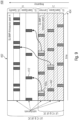
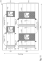
- Fig. 8 illustrates an embodiment of the first aspect of the present invention using a common SL search space or common SL-CORESET in a common bandwidth part or resource pool that is accessible by some or all of the UEs and in case a UE is involved in a sidelink communication with a receiving UE, for example for a unicast transmission or a groupcast transmission, the transmitting UE may signal to the receiving UE a UE-specific search space for the next one or more transmission periods.
- Fig. 8 illustrates an embodiment of the first aspect of the present invention using a common SL search space or common SL-CORESET in a common bandwidth part or resource pool that is accessible by some or all of the UEs and in case a UE is involved in a sidelink communication with a receiving UE, for example for a unicast transmission or a groupcast transmission, the transmitting UE may signal to the receiving UE a UE-specific search space for the next one or more transmission periods.
- Fig. 8 illustrates an embodiment of the
- control resources 402 in the embodiment of Fig. 8 , comprise a first bandwidth part or a first resource pool A and a second bandwidth part or resource pool C.
- a plurality of common SL-search spaces or SL-CORESETs 406 are defined. For example, when considering four UEs to perform a sidelink communication, namely UEs 1B, 2B, 1C and 2C.
- UEs may be configured, for example by the above-described message or information element (see Fig. 6 ) with one or more of the SL-search spaces 406 in the first portion 404 of the resource pool C.
- the common SL search spaces may be used by a transmitting UE and a receiving UE of the SL communication pair to establish initially a SL communication, like a unicast communication or groupcast communication, and once established, the transmitting UE may signal to one or more of the receiving UEs that for one or more of the following transmissions periods a UE specific search space is to be used.
- the UE specific SL-search space for UEs 1B and 2B are within a second portion 408 of the resource pool C, and Fig. 8 illustrates respective UE specific SL-search spaces 410 indicating search occasions for a receiving UE, i.e., occasions where to perform blind decoding to see as to whether sidelink control messages for the UE are transmitted.
- the common and UE specific SL-search spaces are within the same resource pool or bandwidth part, namely within bandwidth part C, however, the common SL search space and the UE specific SL-search space may also be in different bandwidth parts, as is illustrated with reference to Fig. 8 for UEs 1C and 2C.
- the UE specific SL-search spaces 412 for the UEs 1C and 2C are in resource pool C, and the common SL-search spaces are in resource pool A.
- Fig. 9 illustrates an embodiment for the above-described switching from a common search pool to a UE specific search pool.
- Fig. 9 illustrates the upper part from Fig. 8 , namely the first portion 404 or resource pool C as well as the resource pool A.
- the portion 404 of resource pool C holds the common SL search spaces for UEs 1C and 2C.
- the respective search spaces 406 are within respective subbands of the resource pool C.
- a signaling may be included pointing to a UE specific SL search space in the resource pool A to be used by a receiving UE for one or more following transmission periods.
- a sub-channel size in the frequency domain may not be included in the SIB message or in the RRC message, but only a number of symbols may be identified by these messages, and in such embodiments, the format is such that a fixed number of sub-channels is used for providing the common SL search space and/or the UE specific SL search space.
- the SL search space may be signaled (via RRC or SIB) indicating the offset from which the SL-1st stage SCI starts, e.g., via the SL-monitoringfrequency subchannel_offset.
- the SL search space may signaled (via RRC or SIB) indicating the length of the search space in frequency, e.g., SL-monitoringfrequency subchannel_length, like the number of subchannels/RBs, etc.
- the UE may detect a 1st stage subchannel length from, e.g., a decoded/detected DMRS.
- Embodiments of the second aspect provide a SCI or sidelink control message has information embedded therein that indicates a configuration of a further message.
- the further message may include further control information and/or data.
- the sidelink control message may include a first part of the control information, e.g., a first stage SCI, and the further message may include at least a second part of the control information, e.g. a second stage SCI, and/or data to be transmitted or transmission reservation(s) for the data to be transmitted.
- the first stage or first part of a SCI may configure time and frequency resources for the second part or second stage of the SCI and/or for the data transmitting part.
- the first and second parts i.e., the sidelink control message and the further message, may be adjacent or non-adjacent in the time domain, with or without a time gap between the first and second parts.
- the first and second parts may employ adjacent or non-adjacent frequency resources or sub-channels.
- the first and second parts may be in the same resource pool (see Fig. 8 above, lower part) or may be in different resource pools, i.e., be distributed across two or more resource pools, as illustrated above in the upper part of Fig. 8 .
- a time offset between the first and second parts of the SCI/data may be configured, and the time offset may be pre-coded in a lookup table, LUT, for example in case the first stage spans all the frequencies of the second stage, i.e., the first stage or first part of the SCI occupies the same frequencies as the second part of the SCI/data.
- a pointer to a physical channel associated with the first stage may be identified so as to identify in the further message, for example, a control channel, like the PSCCH, and/or a data channel, like the PSSCH, or to identify in the further message only a control channel, like the PSCCH, or only a data channel, like a Physical Sidelink Feedback channel, PSFCH.
- a control channel like the PSCCH
- a data channel like the PSSCH
- first stage or first part SCI design are described in more detail.
- the above-described two-stage SCI decoding may be employed, and a first stage of the SCI, in accordance with the second aspect of the present invention is designed to configure the further message, like second stage or second part and/or a PSSCH containing the data associated with the SL transmission.
- the time and frequency resources for the second stage are configured, and this information may be encoded implicitly or explicitly.
- the format or configuration to be used for the second part may be conveyed for the receiving UE in a UE-common SL space or a UE-specific SL search space as described above with reference to the first aspect.
- one or more of the above-described formats may provide for a multi UE multiplexing approach, for example using CDM or the like, so as to reduce interference in the control channel.
- the above formats may have one symbol, two symbols or three symbols in the time domain, however, in accordance with further embodiments, there may also be provided more than three symbols.
- the above-described formats may be used for a unicast communication, a groupcast communication and/or a broadcast communication, and in any of the formats, a field may be provided to introduce time and frequency locations as well as a field to introduce a periodicity of the transmission.
- the invention is not limited to formats including this information, rather, more simple formats may be provided which do not include the time/frequency location and/or the periodicity.
- Short Format 1 of the Sidelink 1st-Stage SCI e.g., SCI-1st_format_i_i
- a format in accordance with this embodiment may have no information about the time and the frequency resource allocation of the second stage because the time allocation of the first and second stages or parts of the SCI and the PSCCH, the data, is adjacent.
- the frequency allocation i.e., the number of sub-channels allocated for the data and the second stage SCI may be identical.
- the number of used sub-channels may be traced by the number of sub-channels occupied by the first stage.
- the first stage decoding for example by blind decoding or by DMRS scanning, may identify a length of the used sub-channels in the frequency domain.
- a periodicity indicator for example, indicator, maybe provided for indicating a periodic or aperiodic transmission or for indicating a resource release.
- the periodicity field may convey periodicity information is described in more detail below.
- the search space field that may be signaled via SIB/RRC as described above with reference to the first aspect
- the subchannel size in frequency may not be given but only the number of symbols may be identified.
- the length of the 1st stage may be identified, e.g., using DMRS scanning.
- a DMRS length decoded/identified by an RX UE may also indicate the length of the 1st stage in the frequency.
- the format in accordance with this embodiment may identify the following items: Field (Item) Bits Reference Physical channel indicator 1 0: PSCCH/PSSCH 1: PSFICH Frequency domain resource assignment 0 If this field is zero or absent, this indicates that 1 st and 2 nd +Data have the same frequency allocation.
- Time domain resource assignment 0 If this field is zero or absent, this indicates that 1 st and 2 nd +Data have zero gap Periodicity 1 If 0 (or all zeros) no repetitions or release continuous transmission Else, quantized repetitions Priority 1 / 3 1 bit (0 low and 1 high) 3 bits (e.g., 8 PPPP priorities) BC indicator 1 0: Broadcast 1: UC/GC New data indicator (NDI) or retransmission indicator 1 0: new data and 1: retransmission Retransmission gap 1 0: no autonomous retransmission 1: autonomous retransmission is active and retransmission gap as per-configuration
- the size of the time and frequency domain is 0-bits, i.e., is not transmitted or is not part of the SCI message.
- Fig. 10 illustrates an embodiment of the first short SCI first stage format where a time and a frequency of the data and the control are not identified in the first stage.
- Fig. 10 illustrates the sidelink resources 400 used for transmitting sidelink control messages and data.
- the SCI and data for a first UE1 are transmitted in two sub-channels
- the respective SCI and data for a second UE2 are transmitted in four or three sub-channels 416.
- Each transmission of the respective UEs includes a first stage SCI 418 and a second stage SCI 420 that may include also the data to be transmitted by the UE1 to a receiving UE over the sidelink.
- the first stage 418 of the SCI is adjacent to the second stage SCI together with the associated data, i.e., the time offset, T-offset, and the frequency offset, F-offset, is zero or null so that the time offset field in the first stage SCI is set to zero.
- the above-described format does not require to include any bits for the time offset or the frequency offset.
- the format_i_i has a time offset and a frequency offset of null or zero which is recognized by a receiving UE that, therefore, knows that the second stage SCI and the data follows in the same frequency bands immediately after the duration of the first stage SCI.
- the duration of the transmission may be signaled earlier with an RRC/SIB message to all UEs.
- Short Format 2 of the Sidelink 1st-Stage SCI e.g., SCI-1st_format_i _ j
- the format in accordance with this embodiment concerns an allocation of a first stage SCI to identify control or data coming with a time offset T.
- the format of the present embodiment may include a longer periodicity field, for example having more than one bit, so as to consider a further reservation of resources for a transmission.
- the periodicity field may be set to zero meaning that there is no periodic reservation of transmission resources needed or meaning that a reservation that has been made earlier may be released.
- the UE may reserve period or aperiodic resources for transmissions. For example, the UE may decide to send a first stage SCI every period P or the UE may decide to send one first stage every period at the beginning of a periodic transmission, or the UE may decide to occasionally send a refresh first stage SCI.
- the first stage SCI or the first part of the SCI may indicate the following items: Field (Item) Bits Reference Physical channel indicator 1 0: PSCCH/PSSCH 1: PSFICH Frequency domain resource assignment 0 If this field is zero or absent, this indicates that 1 st and 2 nd +Data have the same frequency allocation. Time domain resource assignment 2/3/4 ... Selects from a quantized table with offset as configured by upper layers: e.g., Sl1, Sl2, SL4, SL6, SL8, ... e.g., every slot, every second slot, every fourth slot, ... Periodicity 1/2/3/...
- BC indicator 1 0 Broadcast 1: UC/GC New data indicator (NDI) or retransmission indicator 1 0: new data and 1: retransmission Retransmission gap 1 0: no autonomous retransmission 1: autonomous retransmission is active and retransmission gap as per-configuration
- Fig. 11 illustrates an embodiment of the second short SCI first stage format where time and periodicity, P, for the second stage and the control may be identified within the first stage.
- Fig. 11 in a similar way as in Fig. 10 , illustrates the sidelink resources 400 among which the two sub-channels 414 are used by UE1 and the sub-channels 416 are used by a UE2.
- the first stage SCI 418 may indicate a time offset T-offset of T1 specifying a distance along the time domain between the first stage SCI 420 and the associated second stage SCI or data 420.
- the first stage SCI 418 sent by UE1 indicates a certain periodicity P1 indicating that the second stage SCI and the data 420 may be repeated with a certain periodicity, and in the example depicted in Fig. 11 , the periodicity indicates that the second stage SCI and data 420 is repeated once after the second stage SCI and data.
- a similar approach is described, however, also a first stage SCI is transmitted between the two occurrences of the second stage SCI and data.
- the short format may also include a sub-channel, SC, length in the frequency allocation field.
- SC sub-channel
- the time domain resource assignment may include more than 1 bit, such that the offset time durations may be quantized and used as follows:
- a longer format for the first stage SCI is supported so that, for example, more information about a DMRS pattern associated with the second stage or data may be provided.
- the DMRS pattern may be employed by the receiving UE for decoding the second stage SCI and the data.
- the format in accordance with this embodiment may include a field for the frequency domain resource which may include a frequency domain resource assignment offset, F-offset, and a frequency domain resource assignment channel_length, F-length.
- the F-offset may indicate the offset from the beginning of a resource pool sub-channel, for example from sub-channel zero, or from the beginning of a sub-channel in which the first stage SCI is located. For example, in case the first stage SCI does not span the entire sub-channels also spanned by the second stage, and in case the first and second stages the SCI overlap in the time domain, F-offset may have a negative value.
- the F-offset may indicate a starting point of the data.
- the F-length may indicate the sub-channel lengths of the second stage in the data which may always be possible.
- the format in accordance with the present embodiment may indicate the following items: Field (Item) Bits Reference Physical channel indicator 1 0: PSCCH/PSSCH 1: PSFICH Frequency domain resource assignment.offset 2/4/6/8* Indicate the offset above or below the 1 st -SCI, i.e., +ve or -ve Frequency domain resource assignment.Channel_Lenth 2/4/6/8* indicate the length of the used subchannel starting from the offset Time domain resource assignment 2/3/4 ... Selects from a quantized table with offset as configured by upper layers: Sl1, Sl2, SL4, SL6, SL8, ...
- Slot_duration -or-aggregated_slot 2/3/4 Defines: - 1 st : Slot duration (2, 4, 7, 14 symbols) or - Number of aggregated slots: 00 (1 slot transmission), 01 (2-slot aggregated transmission), 10 (4-slot aggregated transmission), ... so on Periodicity 1/2/3/...
- BC indicator 1 0 Broadcast 1: UC/GC New data indicator (NDI) or retransmission indicator 1 0: new data and 1: retransmission Retransmission gap 1 0: no autonomous retransmission 1: autonomous retransmission is active and retransmission gap as per-configuration DMRS pattern in 2st SCI 2 If needed, a 2 bit maps different (up to 4) DMRS pattern for 2 nd stage and PSSCH CDM group and/or ports 2 For CDM group for 2 nd stage and PSSCH Destination ID 8 Used to identify Unicast and Group cast transmission.
- Timing advance indicator(Mode 1) 11 Indicate the timing advance for mode 1 only (optional for mode 1 only) * :
- the size of the bits of the frequency offset or SC Length may depend on the subcarrier spacing
- the Slot_duration identifying a slot duration, e.g., as number of symbols.
- the slot duration may depend on, e.g., a subcarrier spacing (SCS) or a frequency range (FR1 ⁇ 6/7 GHz or FR2 >7 GHz).
- SCS subcarrier spacing
- FR1 ⁇ 6/7 GHz or FR2 >7 GHz The slot duration may be 1 or more bits quantizing possible slot durations, e.g., for a 2-bit Slot_duration: 00 means 14 symbols, 01 means 7 symbols, 10 means 4 symbols, and 11 means 2 symbols.
- the slot duration may also be indicated with any other format in the 1st stage SCI.
- an Aggregated_slot / or slot_aggregation field may be provided so as to indicate a number of aggregated slots of data with a single control channel.
- 00 means a 1 slot transmission
- 01 means a 2-slot aggregated transmission
- 10 means a 4-slot aggregated transmission
- Other indication formats within the SCI first-stage may also be possible.
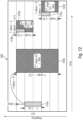
- Fig. 12 illustrates an embodiment of a first long SCI first stage format where time, frequency and periodicity, P, for the second stage are identified in the first stage SCI.
- Fig. 12 illustrates the sidelink resources 400 that are used by a UE1 for transmitting data towards a receiving UE.
- Fig. 12 shows a further example of the format of the present embodiment, in accordance with which the first stage SCI 418a and a second stage SCI and data 420b are adjacent in time and frequency. More specifically, the first stage SCI 418b signals to the receiving UE a F-offset of zero and a T-offset of -1 and 0 as well as a F-length of two sub-channels. In other words, based on this information, the UE that receives the transmission from the UE1, determines from the first stage SCI 418b that the second stage SCI and the data 42b follow immediately the first stage SCI in the first subband and that the first stage SCI and the second stage SCI overlap in the second subband as is illustrated in Fig. 12 .
- FIG. 12 A further embodiment of the format in accordance with the present embodiment is described also in Fig. 12 including a first stage 418c and a second stage SCI and data 420c which is similar to the SCI stages 418b and 420 described above except that the time offset is zero for both subbands, i.e., in the second subband, not covered by the first SCI the second SCI starts also once the first stage SCI terminated.
- the format in accordance with this embodiment allows to cross schedule for different SL resource pools, SL BWPs including the resource pools, SL carriers for multi-carriers.
- This format defines a field including a resource pool ID, a BWP ID or a carrier ID.
- the receiving UE may compute the frequency domain resource assignment offset, F-offset, and the frequency domain resource assignment channel lengths, F-lengths.
- the format in accordance with this embodiment may signal in the first stage the following information.
- offset 2/4/6/8* indicate the offset above or below the 1 st -SCI, i.e., +ve or -ve Frequency domain resource assignment.
- Channel_Lenth 2/4/6/8* indicate the length of the used subchannel starting from the offset Time domain resource assignment 4 Selects from a quantized table with offset as configured by upper layers: Sl1, Sl2, SL4, SL6, SL8, ...
- Timing advance indicator(Mode 1) 11 Indicate the timing advance for mode 1 only (optional for mode 1 only) * :
- the size of the bits of the frequency offset or SC Length may depend on the subcarrier spacing
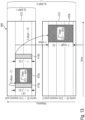
- Fig. 13 illustrates an embodiment of the long format described above with a cross carrier/BWP/resource pool scheduling or the second stage SCI and data that is included in the first stage SCI.
- Fig. 13 illustrates a first example in which a first stage SCI 418a and a second stage SCI and data 420a are in the same resource pool 422, and this may be signaled by the first stage SCI 418a in a way as described above.
- Fig. 13 illustrates a further embodiment in which a first stage SCI 418b indicates that the second stage SCI and data 420b uses resources in a different resource pool, namely resource pool 424.
- a CRC for example of 16 or 24 bits, may be added to any of the above-described formats, preferably for the above-described long SCI first stage formats.
- one or more of the above-described formats may provide for multi UE multiplexing, for example via CDM, so as to reduce interference in the control channel.
- one or more of the above-described formats may include a destination ID, like a UE ID, a group ID, or a broadcast ID that is scrambled with the CRC of the formats so as to allow the receiving UE to identify from the format of the first stage SCI whether the communication is a unicast communication, a group cast communication or broadcast communication by the transmitting UE.
- a destination ID like a UE ID, a group ID, or a broadcast ID that is scrambled with the CRC of the formats so as to allow the receiving UE to identify from the format of the first stage SCI whether the communication is a unicast communication, a group cast communication or broadcast communication by the transmitting UE.
- the first stage SCI may indicate a periodicity.
- the periodicity may be indicated by a variable number of bits, and may be provided for assisting the sensing and the reservation mechanism in the sidelink.
- the periodicity field also referred to as persistence field, is signaled with the first stage SCI. In case the periodicity field indicates a 0, this may mean that a single short transmission occurs without any periodicity, or that a previously set periodicity and associated resources that have been reserved, are released.
- the periodicity may be indicated as per quantized value indicated for each look-up table entry.
- the freed resources may be used by other UEs.
- the periodicity may be signaled as shown in the following tables for a 1 bit periodicity field, a 2 bit periodicity field, a 3 bit periodicity field and X-bits periodicity field.
- All X-bits are zeros No periodicity (1-shot), or Release further reservation (may be last data or a 1st stage sent to release reservation.
- Fig. 14 illustrates an embodiment of the second aspect concerning the periodicity reservation and release using a periodicity field that is provided in the first stage SCI.
- the first stage SCI further includes the periodicity field having a value of "01" signaling to the receiving UE that the second stage resources are reserved with a period of 1, also referred to as a quantized period.
- the fourth first stage SCI 418d includes a periodicity field having a value "00" meaning that a one shot transmission occurs or that the resources reserved so far for the second stage are released.
- Fig. 14 shows a further example, for a second UE2 in which a first stage SCI 418e indicates a time offset T1 between the first stage 418e and the second stage SCI 420e. Further, the periodicity field indicates a value "00", meaning that the transmission is a one shot transmission.
- the periodicity field may be used in the first stage SCI to indicate all upcoming second stage SCls and data occurrences associated with the first stage.
- the data or second stage SCI may come every periodicity.
- the receiving UE receives one first stage SCI, for example the first transmitted first stage SCI, that is to be decoded once by the receiving UE, and for subsequent transmissions of data the UE does not expect any further first stage SCls.
- the transmitting UE may send multiple first stage SCIs so as to reduce a sensing ambiguity of the receiving UEs in case the decoding of the stage SCI that has been transmitted first, is not successful. For example, receiving UEs that did not decode correctly any of the retransmissions of the first stage SCI may rely on the information for further decoding the second stage data and control obtained from the first transmission of the first stage SCI.
- the first stage SCI may be accompanied by a certain reference signal, like a DMRS, having a certain pattern and/or position.
- a certain reference signal like a DMRS
- the first stage of the SCI or the first part of the SCI may be accompanied by a DMRS so as to indicate, in accordance with embodiments, to a receiving UE a cast type of the associated second stage SCI.
- the first stage of the SCI or the first part of the SCI may be accompanied by a DMRS pattern associated with certain use-cases with certain QoS of the second part of the sidelink control message.
- the DMRS design or pattern may be such that a receiving UE is protected from collisions with other UEs.
- the DMRS design may be associated with different 1st SCI formats for conveying certain information about, e.g., a size of the first stage SCI in time and frequency domain, like the length of the DMRS in frequency is the length of the first stage, unless the length in frequency is not conveyed in the search space.
- the receiving UE may identify from a first part of a sidelink control message a reference signal, e.g., the mentioned demodulation reference signal, DMRS, pattern.
- a transmitting UE or another network entity involved in the SL communication like a gNB, may signal to a receiving UE or a group of receiving UEs in or together with the first part of the sidelink control message the reference signal selected so as to convey information to the receiving UE.
- the DMRS defined in Rel-15 NR Uu may be considered a starting point for the NR sidelink DMRS design.
- two types of DMRS configurations both for PUSCH and PDSCH, are defined, namely the type-1 and the type-2 DMRS configuration. These types begin with one or two symbols and are followed, optionally, by at most three additional DMRS symbols depending on the configuration types.
- the DMRS type 1 ensures a sufficient number of DMRS REs per PRB and, in accordance with embodiments, is a preferred PSCCH DMRS structure for the first stage SCI.
- the DMRS structure for the first stage SCI may be received via higher layer signaling, for example by providing a parameter "SL-DMRS-configure-type", or it may be received by a master information block, MIB, or a system information block, SIB.
- SL-DMRS-configure-type a parameter that specifies a DMRS position and a DMRS maximum length.
- other parameters like a DMRS position and a DMRS maximum length may be configured in a similar way.
- the configuration considers only one layer, it is noted that the invention is not limited to such a one layer configuration, rather it is equally applicable to a multilayer configuration.
- the DMRS pattern may be selected dependent on the selected subcarrier frequency mapping, the selected subcarrier time mapping, the orthogonal or quasi orthogonal codes or different code generators or code division multiplexing, CDM.
- the position of the DMRS for different patterns may be computed in a way as described in more detail below.
- the higher signaling message may be the SIB 18/19/21/26 defined for LTE-V2X or another newly defined SIB for NR V2X.
- the DRMS may be defined by an information element named PSCCH-config which may be used to configure UE specific PSCCH parameters per bandwidth part, and Fig. 15 illustrates an embodiment for such a PSCCH-config-common information element. In the information element depicted in Fig.
- SL-dmrs_control_type_x or SL-dmrs_control_type_y_x may contain all positions in time and/or in frequency, SL- dmrs_control_type_1 may be used for broadcast, and SL-dmrs_control_type_2_1 / SL-dmrs_control_2_2 may be used for unicast and/or groupcast.
- Fig. 16 illustrates an embodiment of a PSCCH-config-UE specific information element, also for a common PSCCH in which SL-controlResourceSetToAddModList or SL-controlResourceSetToRelaseModList allow the UE to add or release a search space from the specific search space, the DMRS types are as before, and, if the additionalV2XDMRS field is present, the UE enables DMRS patterns per subcarrier spacing. This is applicable to all formats of PSCCH. This also includes the possibility to have denser DMRS for high speed scenarios as described in more detail below.
- different DMRS patterns may be based on different times/frequencies.
- a certain DMRS pattern may identify a cast type.
- the DMRS may have a pattern that is associated with a certain cast type of the second part of the sidelink control message.
- the DMRS may be selected from a plurality of reference signals, like DMRs, having pattern being different from each other so that each of the plurality of DMRSs is associated with a certain cast type.
- the DMRS may differ in one or more of
- Fig. 17 , Fig. 18 and Fig. 19 illustrate embodiments of DMRS patterns for different first stage SCI types, i.e., the cast type and the first stage SCI is conveyed in one symbol, for example the second symbol.
- the cast type in the depicted embodiments, may be identified by a DMRS pattern having DMRSs located in three subchannels in the second symbol that are separated in the frequency domain by two subchannels.
- a DMRS patters has a certain frequency offset from the start of the PRB.
- Fig. 17 illustrates a DMRS pattern for a 1st stage SCI type identifying a broadcast communication.
- the position of the DMRS in time or frequency is set by upper layers, e.g., by the parameter SL-dmrs_control_fype_xx.
- Fig. 17 illustrates a DMRS pattern 430 having DMRS_1, DMRS_2 and DMRS_3 located in the three subchannels in the second symbol 432 that are separated in the frequency domain by two subchannels 434 1 , 434 2 .
- the DMRS pattern 430 has a frequency offset 436a of three subchannels in the frequency domain indicating a broadcast communication.
- a UE recognizes from the DMRS pattern 430 and the offset 436a that the cast type of the first stage SCI is broadcast.
- Fig. 18 illustrates a DMRS pattern for a 1st stage SCI type identifying a unicast communication.
- the position of the DMRS in time or frequency is set by upper layers, e.g., by the parameter SL-dmrs_control_type_xx.
- Fig. 18 illustrates the same DMRS pattern 430 as in Fig. 17 but with a frequency offset 436b of two subchannels in the frequency domain, thereby indicating a unicast communication.
- a UE recognizes from the DMRS pattern 430 and the offset 436b that the cast type of the first stage SCI is unicast.
- Fig. 19 illustrates a DMRS pattern for a 1st stage SCI type identifying a multicast or groupcast communication.
- the position of the DMRS in time or frequency is set by upper layers, e.g., by the parameter SL-dmrs_control_type_xx.
- Fig. 19 illustrates the same DMRS pattern 430 as in Fig. 17 or in Fig. 18 but with a frequency offset 436c of one subchannel in the frequency domain, thereby indicating a multicast or groupcast communication.
- a UE recognizes from the DMRS pattern 430 and the offset 436c that the cast type of the first stage SCI is multicast or groupcast.
- the positions in time and frequency may be configured using any of the fields, for example, the SIB/RRC fields SL-dmrs_control_type_1 , SL-dmrs_control_type_2_1 / 2 , or any other field defined by upper layer parameters in RRC and/or SIB.
- the DMRS patterns may differ in the coding domain and the space domain (antenna ports).
- the DMRS may be based on code division multiplexing, CDM.
- a variable or configurable DMRS pattern for a data demodulation may be supported.
- a configuration may support a front loaded DMRS pattern.
- a front loaded DMRS may be mapped over one or two adjacent OFDM symbols.
- a DMRS may be configured for a later part of the slot.
- the DMRS configuration may be up to a maximum number of DMRS ports.
- eight orthogonal DL DMRS patterns may be supported for a single user MIMO, SU-MIMO, e.g., the configuration type 1 may be used, and a maximum of 12 orthogonal DL DMRS ports may be supported for multiuser MIMO, MU-MIMO, using for example, the configuration type 2.
- NR may support a common DMRS structure for DL and UL, and the DMRS location and DMRS pattern may be the same or different.
- the DMRS for the respective links may be configured to be orthogonal or quasi-orthogonal to each other.
- FDM including comp
- CDM including OCC and cyclic shift
- TDM time division multiplexing
- some or all of the plurality of reference signals may have a unique design, e.g., orthogonal or quasi-orthogonal DMRS patterns, that allows to protect a receiving UE from collisions.
- PN sequences that are supported in 3GPP may be used to generate a DMRS parameter, for example, by considering the configuration type 1 for PUSCH, as is described in reference [2]. This identifies the positions in time and frequency so as to generate cast specific DMRS identifying whether a transmission is for a broadcast, for a unicast or for a groupcast.
- Embodiments of the third aspect employ the above to provide for an additional degree of freedom for determining DMRS patterns corresponding to the different cast communications at the 1 st stage SCI, e.g., broadcast, unicast or group/multicast.
- An example of deterministic DMRS patterns obtained in accordance with this embodiment is indicated in the table below, however, other patterns are not precluded.
- the parameters P, CDM group, k', I' and ⁇ given in Table 3 are configured by: - higher layer signaling in connected mode, i.e. RRC, - or SIB in idle mode.
- a DMRS pattern may be repeated over the time domain, for example in case of user scenarios in which the users are moving fast.
- a coherence time may be less than a symbol duration in the upper band frequency of FR1.
- the DMRS patterns may be mapped to one or more of the symbols of the first stage SCI.
- a DMRS may be mapped to every symbol of the first stage SCI based on a specific time pattern algorithm corresponding to the cast type communication.
- a certain pattern for mapping the DMRS to the first stage SCI may be employed.
- Fig. 20 illustrates an embodiment using a DMRS shift of a frequency and/or time for different cast types.
- DMRS symbols may only be provided in a subset of the PSCCH symbols in the time domain, so that all DMRS symbols or a subset of the DMRS symbols may be in a first stage SCI associated with the PSCCH.
- a different number of symbols may be provided for the PSCCH, for example, 1, 2, 3, 4 and up to 14 symbols, wherein all the symbols may be associated with a different DMRS configuration.
- different DRMS configurations may be applied.
- the density of the DMRS time-symbols may be increased, using, for example an additional field "additional V2X DMRS" as shown in Fig. 15 , for example for a high speed scenario.
- a receiving UE may determine from the first part of the sidelink control message whether the sidelink control message is intended for the UE.
- a transmitting UE or another network entity involved in the SL communication like a gNB, may signal to a receiving UE or a group of receiving UEs in or together in the first part of the sidelink control message whether the sidelink control message is intended for a receiving UE. For example, this may be signaled by identifying in the first stage SCI or the first part of the sidelink control message a cast type of the transmission associated with the SCI.
- a receiving UE does not expect the second part of the sidelink, i.e., the second part is not intended for the UE and the UE will not perform decoding or the like of the second part, for example in case
- the UE may expect the second part of the sidelink, i.e., process the second part, e.g., decode it and use the information and/or data provided therein.
- the sidelink control message may be scrambled, e.g., using CRC scrambling, with a UE destination ID or a group destination ID or a broadcast ID, and the UE does not expect the second part of the sidelink in case a descrambling yields one or more of:
- the UE may expect the second part of the sidelink.
- the cast type may be signaled via a destination ID, either via a direct signaling in the first stage SCI or by CRC scrambling of the SCI with the destination ID, as described above.
- the cast types unicast or groupcast may be derived from a group destination ID or a UE destination ID, whereas the cast type broadcast may be derived from a flag specified in the configuration of from the configuration that does not include any group destination ID or UE destination ID, i.e., the first part or first stage SCI is defined without any destination ID.
- embodiments of the fourth aspect of the present invention provide for a first stage SCI design that allows for an implicit cast type identification combined with a destination ID.
- using the two stage SCI may enable the UE to derive from the information included in the first stage SCI whether the SCI is relevant for the UE or is intended for the UE, i.e., whether the UE expect a second part SCI or not.
- the location and frequency/time domain of the second stage SCI plus the additional associated data may be provided as described above with reference to the first, second and third aspects of the present invention.
- a unique identification may be employed, for example, as described with reference to the third aspect, a cast type may be derived from a DMRS associated with the first stage SCI.
- embodiments allow deriving the cast type from the source ID and/or the destination ID or from the absence of the source and destination IDs.
- the source ID identification works at least for unicast & groupcast. Source ID here refers to the originator of the unicast communication.
- Source ID here refers to the originator of the groupcast communication (group-leader / group- head). If the UE is still in RRC_connected mode and experienced no radio link failure or handover then, source ID is used to identify the ongoing communication in the first stage. This saves the redundant information from being transmitted like broadcast indicator. This will be updated only if the group leader changes.
- a unicast or a groupcast may be derived from a group destination ID or a UE destination ID included in the first stage SCI.
- a broadcast may be derived from a flag or a bit included in the first stage SCI or from the absence of any destination ID in the first stage SCI, i.e., there is neither a group destination ID nor a UE destination ID included in the first stage SCI meaning that the communication is a broadcast. This may be achieved by sending a first stage SCI with a format which is reduced by removing the respective destination ID.
- different formats for the first stage SCI may be provided, one with a destination ID and another one without a destination ID, the latter one indicating the broadcast.
- a unicast communication may be identified by including a destination ID of the UE to which the unicast communication is directed into the first stage SCI.
- a source ID may be used for identifying an ongoing unicast communication. Source ID here refers to the originator of the unicast communication. If the UE is still in RRC_connected mode and experienced no radio link failure or handover then, source ID is used to identify the ongoing communication in the first stage. This saves the redundant information from being transmitted like broadcast indicator.
- a groupcast communication may be identified by a plurality of destination IDs identifying the UEs involved in a groupcast communication, or by a group destination ID identifying the group of UEs involved in a groupcast communication.
- the source ID may be used as an identification of a groupcast communication, for example in case the source ID is a group head of the group cast communication.
- Source ID here refers to the originator of the groupcast communication (group-leader / group- head). If the UE is still in RRC_connected mode and experienced no radio link failure or handover then, source ID is used to identify the ongoing communication in the first stage. This saves the redundant information from being transmitted like broadcast indicator. This will be updated only if the group leader changes. Note: This will not work in case of dynamic groups
- a broadcast may be identified by the absence of any destination UE ID or group destination ID, i.e., there is not any destination ID within the first stage SCI.
- a further format of the first stage SCI may be employed that is free of the destination IDs.
- a broadcast may be derived from a length of the first stage SCI that, when compared to a first stage SCI including destination IDs is shorter.
- a broadcast specific ID may be employed, or a certain pattern or flag so as to identify the first stage SCI as being associated with a broadcast communication.
- this approach is used in case a destination ID is conveyed in the first SCI or it is scrambled with a CRC of the first stage CSI.
- a flag may be provided that indicates a broadcast or a non-broadcast.
- the receiving UE may derive the information about the cast type implicitly from the received first stage SCI, more specifically from the missing group destination ID or missing UE destination ID or from a broadcast indicating flag.
- a UE destination ID or a group destination ID is included in the first stage SCI, only the UEs for which the unicast communication or the groupcast communication is intended, i.e., a UE having a matching ID, reads or decodes the second stage SCI.
- a broadcast ID may include multiple bits, for example 8 bits, in line with the group destination ID, or a 1 bit indication may be used for indicating broadcast, and the other bit fields may be used for other information.
- UE does not to expect, e.g., does not read or does not decode, the second part of the sidelink control message in case
- the UE may expect, e.g., read or decode, the second part of the sidelink control message in case the first part of the sidelink control message includes
- the first part of the sidelink control message includes a broadcast ID and a UE or group ID so that, in case the broadcast ID indicates a broadcast type of communication, e.g., a broadcast flag is set to a first value, the UE determines the second part of the sidelink control message to be relevant for the UE, and is to expect, e.g., is to read or is to decode, the second part of the sidelink control message, and, in case the broadcast ID indicates a non-broadcast type of communication, e.g., a broadcast flag is set to a second value, the UE is to determine from the UE or group ID whether the second part is relevant UE, e.g., when the UE or group ID match an ID of the UE, and is to expect, e.g., is to read or is to decode, a relevant second part of the sidelink control message.
- a broadcast type of communication e.g., a broadcast flag is set to a first value
- the UE determines the second
- the sidelink control message may be scrambled, e.g., using CRC scrambling, with a UE ID or a group ID or a broadcast ID.
- the UE does not expect, e.g., does not read or does not decode, the second part of the sidelink control message in case a descrambling yields one or more of:
- the UE may derive, e.g., implicitly, a cast type from a UE ID or a group ID or a broadcast ID or an absence of any ID in the first part of the sidelink control message as follows:
- a broadcast may be a single-stage broadcast, e.g., all information is included in a single message.
- there is no second part of the sidelink control message and the UE does not expect, e.g., does not read or does not decode, the second part of the sidelink control message in case the first part of the sidelink control message includes a broadcast ID indicating a broadcast type of communication.
- a UE may have multiple destination L1/L2 IDs and/or multiple source L1/L2 IDs depending on different transmission/receptions, e.g. unicast, groupcast and multicast.
- Embodiments of the present invention have been described in detail above with reference to a sidelink communication using the PC5 interface.
- the present invention is not limited to the use of the PC5 interface. Any other interface allowing for a direct communication among one or more UEs may be employed, e.g., interfaces according to the IEEE 802.11p standard, the IEEE 802.15.4 standard (Zigbee), and others.
- a base station e.g., the connected mode, also referred to as NR mode 1 or LTE mode 3 configuration
- vehicles being in a mode in which when no SL resource allocation configuration or assistance is provided by a base station, e.g., the idle mode, also referred to as NR mode 2 or LTE mode 4 configuration.
- the present invention is not limited to V2V communications or V2X communications, rather it is also applicable to any device-to-device communications, for example non-vehicular mobile users or stationary users that perform a sidelink communication, e.g., over the PC5 interface. Also, in such scenarios, the inventive aspects described above may be employed.
- the wireless communication system may include a terrestrial network, or a non-terrestrial network, or networks or segments of networks using as a receiver an airborne vehicle or a spaceborne vehicle, or a combination thereof.
- a receiver may comprise one or more of a mobile or stationary terminal, an loT device, a ground-based vehicle, an aerial vehicle, a drone, a building, or any other item or device provided with network connectivity enabling the item/device to communicate using the wireless communication system, like a sensor or actuator.
- a transmitter may comprise one or more of a macro cell base station, or a small cell base station, or a spaceborne vehicle, like a satellite or a space, or an airborne vehicle, like a unmanned aircraft system (UAS), e.g., a tethered UAS, a lighter than air UAS (LTA), a heavier than air UAS (HTA) and a high altitude UAS platforms (HAPs), or any transmission/reception point (TRP) enabling an item or a device provided with network connectivity to communicate using the wireless communication system.
- UAS unmanned aircraft system
- LTA lighter than air UAS
- HTA heavier than air UAS
- HAPs high altitude UAS platforms
- TRP transmission/reception point
- aspects of the described concept have been described in the context of an apparatus, it is clear that these aspects also represent a description of the corresponding method, where a block or a device corresponds to a method step or a feature of a method step. Analogously, aspects described in the context of a method step also represent a description of a corresponding block or item or feature of a corresponding apparatus.
- Various elements and features of the present invention may be implemented in hardware using analog and/or digital circuits, in software, through the execution of instructions by one or more general purpose or special-purpose processors, or as a combination of hardware and software.
- embodiments of the present invention may be implemented in the environment of a computer system or another processing system.
- Fig. 21 illustrates an example of a computer system 500.
- the units or modules as well as the steps of the methods performed by these units may execute on one or more computer systems 500.
- the computer system 500 includes one or more processors 502, like a special purpose or a general-purpose digital signal processor.
- the processor 502 is connected to a communication infrastructure 504, like a bus or a network.
- the computer system 500 includes a main memory 506, e.g., a random-access memory (RAM), and a secondary memory 508, e.g., a hard disk drive and/or a removable storage drive.
- the secondary memory 508 may allow computer programs or other instructions to be loaded into the computer system 500.
- the computer system 500 may further include a communications interface 510 to allow software and data to be transferred between computer system 500 and external devices.
- the communication may be in the from electronic, electromagnetic, optical, or other signals capable of being handled by a communications interface.
- the communication may use a wire or a cable, fiber optics, a phone line, a cellular phone link, an RF link and other communications channels 512.
- computer program medium and “computer readable medium” are used to generally refer to tangible storage media such as removable storage units or a hard disk installed in a hard disk drive.
- These computer program products are means for providing software to the computer system 500.
- the computer programs also referred to as computer control logic, are stored in main memory 506 and/or secondary memory 508. Computer programs may also be received via the communications interface 510.
- the computer program when executed, enables the computer system 500 to implement the present invention.
- the computer program when executed, enables processor 502 to implement the processes of the present invention, such as any of the methods described herein. Accordingly, such a computer program may represent a controller of the computer system 500.
- the software may be stored in a computer program product and loaded into computer system 500 using a removable storage drive, an interface, like communications interface 510.
- the implementation in hardware or in software may be performed using a digital storage medium, for example cloud storage, a floppy disk, a DVD, a Blue-Ray, a CD, a ROM, a PROM, an EPROM, an EEPROM or a FLASH memory, having electronically readable control signals stored thereon, which cooperate (or are capable of cooperating) with a programmable computer system such that the respective method is performed. Therefore, the digital storage medium may be computer readable.
- a digital storage medium for example cloud storage, a floppy disk, a DVD, a Blue-Ray, a CD, a ROM, a PROM, an EPROM, an EEPROM or a FLASH memory, having electronically readable control signals stored thereon, which cooperate (or are capable of cooperating) with a programmable computer system such that the respective method is performed. Therefore, the digital storage medium may be computer readable.
- Some embodiments according to the invention comprise a data carrier having electronically readable control signals, which are capable of cooperating with a programmable computer system, such that one of the methods described herein is performed.
- embodiments of the present invention may be implemented as a computer program product with a program code, the program code being operative for performing one of the methods when the computer program product runs on a computer.
- the program code may for example be stored on a machine readable carrier.
- inventions comprise the computer program for performing one of the methods described herein, stored on a machine readable carrier.
- an embodiment of the inventive method is, therefore, a computer program having a program code for performing one of the methods described herein, when the computer program runs on a computer.
- a further embodiment of the inventive methods is, therefore, a data carrier (or a digital storage medium, or a computer-readable medium) comprising, recorded thereon, the computer program for performing one of the methods described herein.
- a further embodiment of the inventive method is, therefore, a data stream or a sequence of signals representing the computer program for performing one of the methods described herein. The data stream or the sequence of signals may for example be configured to be transferred via a data communication connection, for example via the Internet.
- a further embodiment comprises a processing means, for example a computer, or a programmable logic device, configured to or adapted to perform one of the methods described herein.
- a further embodiment comprises a computer having installed thereon the computer program for performing one of the methods described herein.
- a programmable logic device for example a field programmable gate array
- a field programmable gate array may cooperate with a microprocessor in order to perform one of the methods described herein.
- the methods are preferably performed by any hardware apparatus.
Landscapes
- Engineering & Computer Science (AREA)
- Signal Processing (AREA)
- Computer Networks & Wireless Communication (AREA)
- Quality & Reliability (AREA)
- Computer Security & Cryptography (AREA)
- Multimedia (AREA)
- Mobile Radio Communication Systems (AREA)
Applications Claiming Priority (3)
| Application Number | Priority Date | Filing Date | Title |
|---|---|---|---|
| EP19191838 | 2019-08-14 | ||
| EP20753363.9A EP4014691B1 (fr) | 2019-08-14 | 2020-08-10 | Conception de message de commande de liaison latérale nr |
| PCT/EP2020/072388 WO2021028387A1 (fr) | 2019-08-14 | 2020-08-10 | Conception de message de commande de liaison latérale nr |
Related Parent Applications (2)
| Application Number | Title | Priority Date | Filing Date |
|---|---|---|---|
| EP20753363.9A Division-Into EP4014691B1 (fr) | 2019-08-14 | 2020-08-10 | Conception de message de commande de liaison latérale nr |
| EP20753363.9A Division EP4014691B1 (fr) | 2019-08-14 | 2020-08-10 | Conception de message de commande de liaison latérale nr |
Publications (2)
| Publication Number | Publication Date |
|---|---|
| EP4319030A2 true EP4319030A2 (fr) | 2024-02-07 |
| EP4319030A3 EP4319030A3 (fr) | 2024-04-17 |
Family
ID=67658888
Family Applications (2)
| Application Number | Title | Priority Date | Filing Date |
|---|---|---|---|
| EP23215059.9A Pending EP4319030A3 (fr) | 2019-08-14 | 2020-08-10 | Conception de message de commande de liaison latérale nr |
| EP20753363.9A Active EP4014691B1 (fr) | 2019-08-14 | 2020-08-10 | Conception de message de commande de liaison latérale nr |
Family Applications After (1)
| Application Number | Title | Priority Date | Filing Date |
|---|---|---|---|
| EP20753363.9A Active EP4014691B1 (fr) | 2019-08-14 | 2020-08-10 | Conception de message de commande de liaison latérale nr |
Country Status (7)
| Country | Link |
|---|---|
| US (1) | US12382430B2 (fr) |
| EP (2) | EP4319030A3 (fr) |
| JP (1) | JP7330362B2 (fr) |
| KR (1) | KR20220047608A (fr) |
| CN (1) | CN114557092B (fr) |
| ES (1) | ES2980960T3 (fr) |
| WO (1) | WO2021028387A1 (fr) |
Families Citing this family (36)
| Publication number | Priority date | Publication date | Assignee | Title |
|---|---|---|---|---|
| WO2020204642A1 (fr) * | 2019-04-02 | 2020-10-08 | 엘지전자 주식회사 | Procédé et dispositif de transmission de pscch et pssch |
| US11522661B2 (en) * | 2019-04-12 | 2022-12-06 | Qualcomm Incorporated | Reference signal patterns based on relative speed between a transmitter and receiver |
| KR102892809B1 (ko) * | 2019-08-14 | 2025-11-28 | 삼성전자주식회사 | 무선 통신 시스템에서 harq 피드백 방법 및 장치 |
| WO2021034124A1 (fr) * | 2019-08-21 | 2021-02-25 | 현대자동차주식회사 | Procédé et dispositif de réservation de ressource de liaison latérale dans un système de communication |
| US20210067290A1 (en) * | 2019-08-26 | 2021-03-04 | Mediatek Singapore Pte. Ltd. | Sidelink communications with two-stage sidelink control information |
| WO2021056568A1 (fr) * | 2019-09-29 | 2021-04-01 | 华为技术有限公司 | Procédés d'envoi et de réception d'informations de commande de liaison latérale, appareil terminal et système |
| US11503573B2 (en) * | 2019-11-11 | 2022-11-15 | Qualcomm Incorporated | Techniques for multi-user superposition transmission sidelink feedback |
| US20230056831A1 (en) * | 2020-03-20 | 2023-02-23 | Qualcomm Incorporated | Methods and apparatuses for sidelink-assisted cooperative positioning |
| US11570652B2 (en) * | 2020-05-19 | 2023-01-31 | T-Mobile Usa, Inc. | Bandwidth part configuration for network slicing |
| US11785633B2 (en) | 2020-05-19 | 2023-10-10 | T-Mobile Usa, Inc. | Base station radio resource management for network slices |
| US11659444B1 (en) | 2020-05-19 | 2023-05-23 | T-Mobile Usa, Inc. | Base station management of end-to-end network latency |
| US12150187B2 (en) * | 2020-07-24 | 2024-11-19 | Qualcomm Incorporated | Techniques for configuring search spaces for reverse sidelink communication |
| WO2022021292A1 (fr) * | 2020-07-31 | 2022-02-03 | 北京小米移动软件有限公司 | Procédé et appareil d'accès aléatoire, et procédé et appareil d'indication de configuration |
| US11800491B2 (en) * | 2020-08-25 | 2023-10-24 | Qualcomm Incorporated | Resource pool-based communications for sidelink |
| US12284644B2 (en) * | 2021-01-22 | 2025-04-22 | Qualcomm Incorporated | Techniques for sidelink resource information forwarding |
| US11683727B2 (en) * | 2021-03-31 | 2023-06-20 | Qualcomm Incorporated | Coexistence of redcap and non-redcap UEs in SL |
| US11863972B2 (en) * | 2021-04-22 | 2024-01-02 | Qualcomm Incorporated | Resolving reservation ambiguity of sidelink control information repetition in sidelink communications |
| US11889517B2 (en) * | 2021-05-05 | 2024-01-30 | Qualcomm Incorporated | Configured chase-combining reception for new radio (NR) sidelink mode 1 |
| WO2022267593A1 (fr) * | 2021-06-21 | 2022-12-29 | 华为技术有限公司 | Procédé et dispositif de communication |
| US20230007462A1 (en) * | 2021-07-02 | 2023-01-05 | Qualcomm Incorporated | Discovery signal transmission for sidelink communication over unlicensed band |
| CN115701190A (zh) * | 2021-07-14 | 2023-02-07 | 索尼集团公司 | 用于无线通信的管理电子设备、成员电子设备以及方法 |
| WO2023283908A1 (fr) * | 2021-07-16 | 2023-01-19 | Qualcomm Incorporated | Configuration de ressources de coordination – coordination inter-ue |
| US12207257B2 (en) * | 2021-08-02 | 2025-01-21 | Qualcomm Incorporated | Sidelink resource reservation and selection |
| US11737096B2 (en) * | 2021-08-02 | 2023-08-22 | Qualcomm Incorporated | Sidelink bandwidth parts with sidelink carrier aggregation |
| WO2023010399A1 (fr) * | 2021-08-05 | 2023-02-09 | 富士通株式会社 | Appareil et procédé de coordination entre dispositifs |
| US11805511B2 (en) * | 2021-08-20 | 2023-10-31 | Qualcomm Incorporated | Cross-slot schedule for new radio (NR) sidelink (SL) |
| US20230062970A1 (en) * | 2021-08-26 | 2023-03-02 | Qualcomm Incorporated | Techniques for destination filtering in first-stage sidelink control information |
| US11930498B2 (en) * | 2021-09-07 | 2024-03-12 | Qualcomm Incorporated | Techniques for scheduling sidelink communications in multiple time periods |
| US11778517B2 (en) * | 2021-09-14 | 2023-10-03 | Qualcomm Incorporated | Resource reservation information sharing with data |
| US12063627B2 (en) * | 2021-11-18 | 2024-08-13 | Qualcomm Incorporated | Enhanced sidelink resource pools |
| US12526784B2 (en) * | 2021-12-07 | 2026-01-13 | Qualcomm Incorporated | Scrambling sidelink control information in sidelink communication |
| US12225532B2 (en) * | 2022-01-20 | 2025-02-11 | Qualcomm Incorporated | Sidelink reference signal and measurement report sharing |
| US12185263B2 (en) * | 2022-01-31 | 2024-12-31 | Qualcomm Incorporated | Aperiodic tracking reference signals for sidelink communications |
| US20250151087A1 (en) * | 2022-02-11 | 2025-05-08 | Apple Inc. | Methods and systems for inter-ue coordination scheme1 |
| CN115102605B (zh) * | 2022-06-10 | 2023-10-17 | 北京交通大学 | 结合均分与编码域非正交的低轨卫星星群组网方法 |
| KR20250108616A (ko) * | 2022-11-15 | 2025-07-15 | 엘지전자 주식회사 | 유니캐스트 또는 그룹캐스트 기반의 지도정보 및 신호정보 제공 방법 및 장치 |
Family Cites Families (8)
| Publication number | Priority date | Publication date | Assignee | Title |
|---|---|---|---|---|
| EP3455985B1 (fr) * | 2016-05-11 | 2022-03-09 | Convida Wireless, LLC | Nouveau canal de commande de liaison descendante radio |
| WO2018027528A1 (fr) * | 2016-08-09 | 2018-02-15 | Panasonic Intellectual Property Corporation Of America | Sélection et détection améliorées de ressources radio destinées aux transmissions v2x |
| JP2018029323A (ja) * | 2016-08-10 | 2018-02-22 | ソニー株式会社 | 通信装置及び通信方法 |
| US10154481B2 (en) * | 2016-11-15 | 2018-12-11 | Qualcomm Incorporated | Optimization of search space and sounding reference signal placement for improved decoding timeline |
| WO2018145019A1 (fr) * | 2017-02-06 | 2018-08-09 | Intel IP Corporation | Transmission de pdcch (canal de commande de liaison descendante physique) commun de groupe pour nr (nouvelle radio) |
| FI3603293T3 (fi) * | 2017-03-23 | 2023-04-03 | Apple Inc | Priorisoitu viestinvälitys ja resurssin valinta ajoneuvojen välistä (v2v) sivuyhteysviestintää varten |
| WO2018228527A1 (fr) | 2017-06-16 | 2018-12-20 | Telefonaktiebolaget Lm Ericsson (Publ) | Procédé, dispositif terminal et dispositif de réseau destinés à la gestion de coexistence de dispositifs terminaux comportant différents ensembles de capacité de liaison latérale |
| CN113574964B (zh) * | 2019-03-22 | 2024-07-09 | 联想(新加坡)私人有限公司 | 调度用户设备的选择 |
-
2020
- 2020-08-10 EP EP23215059.9A patent/EP4319030A3/fr active Pending
- 2020-08-10 ES ES20753363T patent/ES2980960T3/es active Active
- 2020-08-10 WO PCT/EP2020/072388 patent/WO2021028387A1/fr not_active Ceased
- 2020-08-10 JP JP2022508896A patent/JP7330362B2/ja active Active
- 2020-08-10 CN CN202080071487.6A patent/CN114557092B/zh active Active
- 2020-08-10 KR KR1020227008340A patent/KR20220047608A/ko active Pending
- 2020-08-10 EP EP20753363.9A patent/EP4014691B1/fr active Active
-
2022
- 2022-02-07 US US17/666,040 patent/US12382430B2/en active Active
Non-Patent Citations (8)
| Title |
|---|
| "E-UTRA; Physical channels and modulation (Release 15", 3GPP TS 36.211, June 2019 (2019-06-01) |
| "E-UTRA; Physical layer procedures (Release 15", 3GPP TS 36.213, June 2019 (2019-06-01) |
| "NR Study on Vehicle-to-everything", TR 38.885 3GPP TR 38.885, March 2019 (2019-03-01) |
| "Proximity-based services (ProSe); Stage 2 (Release 15", 3GPP TS 23.303, June 2017 (2017-06-01) |
| "RAN1#97 Chairman's Notes Chairman's Notes", 3GPP TSG RAN WG1 #97, May 2019 (2019-05-01) |
| LG ELECTRONICS, HUAWEI: "Revised WID on 5G V2X with NR sidelink", RP-190984 3GPP TDOC RP-190984, June 2019 (2019-06-01) |
| SAMSUNG: "Feature lead summary#4 for 7.2.4.1", R1-1907924 3GPP TDOC R1-1907924, May 2019 (2019-05-01) |
| T.S. RAPPAPORT: "Wireless Communications", 2002, PRENTICE HALL |
Also Published As
| Publication number | Publication date |
|---|---|
| US20220225292A1 (en) | 2022-07-14 |
| CN114557092A (zh) | 2022-05-27 |
| ES2980960T3 (es) | 2024-10-03 |
| JP7330362B2 (ja) | 2023-08-21 |
| CN114557092B (zh) | 2025-09-09 |
| WO2021028387A1 (fr) | 2021-02-18 |
| JP2022544513A (ja) | 2022-10-19 |
| EP4014691B1 (fr) | 2024-03-20 |
| EP4014691A1 (fr) | 2022-06-22 |
| EP4319030A3 (fr) | 2024-04-17 |
| US12382430B2 (en) | 2025-08-05 |
| KR20220047608A (ko) | 2022-04-18 |
Similar Documents
| Publication | Publication Date | Title |
|---|---|---|
| US12382430B2 (en) | NR sidelink control message design | |
| US12301363B2 (en) | Method and apparatus for transmitting and receiving sidelink HARQ feedback information | |
| US12302457B2 (en) | Advanced feedback in sidelink | |
| US11818078B2 (en) | Method for performing sidelink communication and device therefor | |
| US11589349B2 (en) | Method and apparatus for transmitting and receiving sidelink HARQ feedback information | |
| US11405144B2 (en) | Method and apparatus for transmitting sidelink HARQ feedback information | |
| US11160053B2 (en) | Method and apparatus for transmitting and receiving sidelink data | |
| US11405143B2 (en) | Method and apparatus for transmitting sidelink HARQ feedback information | |
| US11356212B2 (en) | Method and apparatus for transmitting and receiving sidelink HARQ feedback information | |
| US11539475B2 (en) | Method and apparatus for transmitting sidelink HARQ feedback information | |
| US11546095B2 (en) | Sidelink HARQ feedback transmission method and device thereof | |
| CN116963292A (zh) | 用于侧行通信和资源分配的方法和设备 | |
| US11689342B2 (en) | Method for performing sidelink communication and device therefor | |
| US11375530B2 (en) | Method and apparatus for transmitting and receiving information regarding modulation and demodulation in sidelink communication | |
| WO2020064176A1 (fr) | Communication de liaison latérale flexible |
Legal Events
| Date | Code | Title | Description |
|---|---|---|---|
| PUAI | Public reference made under article 153(3) epc to a published international application that has entered the european phase |
Free format text: ORIGINAL CODE: 0009012 |
|
| STAA | Information on the status of an ep patent application or granted ep patent |
Free format text: STATUS: THE APPLICATION HAS BEEN PUBLISHED |
|
| AC | Divisional application: reference to earlier application |
Ref document number: 4014691 Country of ref document: EP Kind code of ref document: P |
|
| AK | Designated contracting states |
Kind code of ref document: A2 Designated state(s): AL AT BE BG CH CY CZ DE DK EE ES FI FR GB GR HR HU IE IS IT LI LT LU LV MC MK MT NL NO PL PT RO RS SE SI SK SM TR |
|
| REG | Reference to a national code |
Ref country code: DE Ref legal event code: R079 Free format text: PREVIOUS MAIN CLASS: H04L0005000000 Ipc: H04W0084000000 |
|
| PUAL | Search report despatched |
Free format text: ORIGINAL CODE: 0009013 |
|
| AK | Designated contracting states |
Kind code of ref document: A3 Designated state(s): AL AT BE BG CH CY CZ DE DK EE ES FI FR GB GR HR HU IE IS IT LI LT LU LV MC MK MT NL NO PL PT RO RS SE SI SK SM TR |
|
| RIC1 | Information provided on ipc code assigned before grant |
Ipc: H04L 1/18 20230101ALN20240312BHEP Ipc: H04L 1/00 20060101ALN20240312BHEP Ipc: H04L 5/00 20060101ALI20240312BHEP Ipc: H04W 4/40 20180101ALI20240312BHEP Ipc: H04W 76/14 20180101ALI20240312BHEP Ipc: H04W 84/00 20090101AFI20240312BHEP |
|
| STAA | Information on the status of an ep patent application or granted ep patent |
Free format text: STATUS: REQUEST FOR EXAMINATION WAS MADE |
|
| 17P | Request for examination filed |
Effective date: 20240926 |
|
| RBV | Designated contracting states (corrected) |
Designated state(s): AL AT BE BG CH CY CZ DE DK EE ES FI FR GB GR HR HU IE IS IT LI LT LU LV MC MK MT NL NO PL PT RO RS SE SI SK SM TR |
|
| GRAP | Despatch of communication of intention to grant a patent |
Free format text: ORIGINAL CODE: EPIDOSNIGR1 |
|
| STAA | Information on the status of an ep patent application or granted ep patent |
Free format text: STATUS: GRANT OF PATENT IS INTENDED |
|
| RIC1 | Information provided on ipc code assigned before grant |
Ipc: H04W 84/00 20090101AFI20260303BHEP Ipc: H04W 76/14 20180101ALI20260303BHEP Ipc: H04W 4/40 20180101ALI20260303BHEP Ipc: H04L 5/00 20060101ALI20260303BHEP Ipc: H04W 72/20 20230101ALI20260303BHEP Ipc: H04L 1/00 20060101ALN20260303BHEP Ipc: H04L 1/18 20230101ALN20260303BHEP |
|
| RIC1 | Information provided on ipc code assigned before grant |
Ipc: H04W 84/00 20090101AFI20260319BHEP Ipc: H04W 76/14 20180101ALI20260319BHEP Ipc: H04W 4/40 20180101ALI20260319BHEP Ipc: H04L 5/00 20060101ALI20260319BHEP Ipc: H04W 72/20 20230101ALI20260319BHEP Ipc: H04L 1/00 20060101ALN20260319BHEP Ipc: H04L 1/18 20230101ALN20260319BHEP |
|
| INTG | Intention to grant announced |
Effective date: 20260326 |