EP4319115A1 - Dispositif électronique comprenant un affichage et une caméra, et son procédé de commande - Google Patents
Dispositif électronique comprenant un affichage et une caméra, et son procédé de commande Download PDFInfo
- Publication number
- EP4319115A1 EP4319115A1 EP22856216.1A EP22856216A EP4319115A1 EP 4319115 A1 EP4319115 A1 EP 4319115A1 EP 22856216 A EP22856216 A EP 22856216A EP 4319115 A1 EP4319115 A1 EP 4319115A1
- Authority
- EP
- European Patent Office
- Prior art keywords
- region
- display
- camera
- user interface
- electronic device
- Prior art date
- Legal status (The legal status is an assumption and is not a legal conclusion. Google has not performed a legal analysis and makes no representation as to the accuracy of the status listed.)
- Pending
Links
Images










Classifications
-
- G—PHYSICS
- G09—EDUCATION; CRYPTOGRAPHY; DISPLAY; ADVERTISING; SEALS
- G09G—ARRANGEMENTS OR CIRCUITS FOR CONTROL OF INDICATING DEVICES USING STATIC MEANS TO PRESENT VARIABLE INFORMATION
- G09G3/00—Control arrangements or circuits, of interest only in connection with visual indicators other than cathode-ray tubes
- G09G3/20—Control arrangements or circuits, of interest only in connection with visual indicators other than cathode-ray tubes for presentation of an assembly of a number of characters, e.g. a page, by composing the assembly by combination of individual elements arranged in a matrix no fixed position being assigned to or needed to be assigned to the individual characters or partial characters
- G09G3/2092—Details of a display terminals using a flat panel, the details relating to the control arrangement of the display terminal and to the interfaces thereto
- G09G3/2096—Details of the interface to the display terminal specific for a flat panel
-
- G—PHYSICS
- G09—EDUCATION; CRYPTOGRAPHY; DISPLAY; ADVERTISING; SEALS
- G09G—ARRANGEMENTS OR CIRCUITS FOR CONTROL OF INDICATING DEVICES USING STATIC MEANS TO PRESENT VARIABLE INFORMATION
- G09G3/00—Control arrangements or circuits, of interest only in connection with visual indicators other than cathode-ray tubes
- G09G3/20—Control arrangements or circuits, of interest only in connection with visual indicators other than cathode-ray tubes for presentation of an assembly of a number of characters, e.g. a page, by composing the assembly by combination of individual elements arranged in a matrix no fixed position being assigned to or needed to be assigned to the individual characters or partial characters
- G09G3/2092—Details of a display terminals using a flat panel, the details relating to the control arrangement of the display terminal and to the interfaces thereto
-
- G—PHYSICS
- G06—COMPUTING OR CALCULATING; COUNTING
- G06F—ELECTRIC DIGITAL DATA PROCESSING
- G06F1/00—Details not covered by groups G06F3/00 - G06F13/00 and G06F21/00
- G06F1/16—Constructional details or arrangements
- G06F1/1613—Constructional details or arrangements for portable computers
- G06F1/1633—Constructional details or arrangements of portable computers not specific to the type of enclosures covered by groups G06F1/1615 - G06F1/1626
- G06F1/1637—Details related to the display arrangement, including those related to the mounting of the display in the housing
-
- G—PHYSICS
- G06—COMPUTING OR CALCULATING; COUNTING
- G06F—ELECTRIC DIGITAL DATA PROCESSING
- G06F1/00—Details not covered by groups G06F3/00 - G06F13/00 and G06F21/00
- G06F1/16—Constructional details or arrangements
- G06F1/1613—Constructional details or arrangements for portable computers
- G06F1/1633—Constructional details or arrangements of portable computers not specific to the type of enclosures covered by groups G06F1/1615 - G06F1/1626
- G06F1/1637—Details related to the display arrangement, including those related to the mounting of the display in the housing
- G06F1/1652—Details related to the display arrangement, including those related to the mounting of the display in the housing the display being flexible, e.g. mimicking a sheet of paper, or rollable
-
- G—PHYSICS
- G06—COMPUTING OR CALCULATING; COUNTING
- G06F—ELECTRIC DIGITAL DATA PROCESSING
- G06F1/00—Details not covered by groups G06F3/00 - G06F13/00 and G06F21/00
- G06F1/16—Constructional details or arrangements
- G06F1/1613—Constructional details or arrangements for portable computers
- G06F1/1633—Constructional details or arrangements of portable computers not specific to the type of enclosures covered by groups G06F1/1615 - G06F1/1626
- G06F1/1684—Constructional details or arrangements related to integrated I/O peripherals not covered by groups G06F1/1635 - G06F1/1675
- G06F1/1686—Constructional details or arrangements related to integrated I/O peripherals not covered by groups G06F1/1635 - G06F1/1675 the I/O peripheral being an integrated camera
-
- G—PHYSICS
- G06—COMPUTING OR CALCULATING; COUNTING
- G06F—ELECTRIC DIGITAL DATA PROCESSING
- G06F1/00—Details not covered by groups G06F3/00 - G06F13/00 and G06F21/00
- G06F1/16—Constructional details or arrangements
- G06F1/18—Packaging or power distribution
- G06F1/181—Enclosures
-
- G—PHYSICS
- G06—COMPUTING OR CALCULATING; COUNTING
- G06F—ELECTRIC DIGITAL DATA PROCESSING
- G06F3/00—Input arrangements for transferring data to be processed into a form capable of being handled by the computer; Output arrangements for transferring data from processing unit to output unit, e.g. interface arrangements
- G06F3/01—Input arrangements or combined input and output arrangements for interaction between user and computer
- G06F3/048—Interaction techniques based on graphical user interfaces [GUI]
- G06F3/0481—Interaction techniques based on graphical user interfaces [GUI] based on specific properties of the displayed interaction object or a metaphor-based environment, e.g. interaction with desktop elements like windows or icons, or assisted by a cursor's changing behaviour or appearance
- G06F3/04817—Interaction techniques based on graphical user interfaces [GUI] based on specific properties of the displayed interaction object or a metaphor-based environment, e.g. interaction with desktop elements like windows or icons, or assisted by a cursor's changing behaviour or appearance using icons
-
- G—PHYSICS
- G06—COMPUTING OR CALCULATING; COUNTING
- G06F—ELECTRIC DIGITAL DATA PROCESSING
- G06F3/00—Input arrangements for transferring data to be processed into a form capable of being handled by the computer; Output arrangements for transferring data from processing unit to output unit, e.g. interface arrangements
- G06F3/01—Input arrangements or combined input and output arrangements for interaction between user and computer
- G06F3/048—Interaction techniques based on graphical user interfaces [GUI]
- G06F3/0484—Interaction techniques based on graphical user interfaces [GUI] for the control of specific functions or operations, e.g. selecting or manipulating an object, an image or a displayed text element, setting a parameter value or selecting a range
- G06F3/04845—Interaction techniques based on graphical user interfaces [GUI] for the control of specific functions or operations, e.g. selecting or manipulating an object, an image or a displayed text element, setting a parameter value or selecting a range for image manipulation, e.g. dragging, rotation, expansion or change of colour
-
- G—PHYSICS
- G06—COMPUTING OR CALCULATING; COUNTING
- G06F—ELECTRIC DIGITAL DATA PROCESSING
- G06F3/00—Input arrangements for transferring data to be processed into a form capable of being handled by the computer; Output arrangements for transferring data from processing unit to output unit, e.g. interface arrangements
- G06F3/01—Input arrangements or combined input and output arrangements for interaction between user and computer
- G06F3/048—Interaction techniques based on graphical user interfaces [GUI]
- G06F3/0487—Interaction techniques based on graphical user interfaces [GUI] using specific features provided by the input device, e.g. functions controlled by the rotation of a mouse with dual sensing arrangements, or of the nature of the input device, e.g. tap gestures based on pressure sensed by a digitiser
- G06F3/0488—Interaction techniques based on graphical user interfaces [GUI] using specific features provided by the input device, e.g. functions controlled by the rotation of a mouse with dual sensing arrangements, or of the nature of the input device, e.g. tap gestures based on pressure sensed by a digitiser using a touch-screen or digitiser, e.g. input of commands through traced gestures
- G06F3/04886—Interaction techniques based on graphical user interfaces [GUI] using specific features provided by the input device, e.g. functions controlled by the rotation of a mouse with dual sensing arrangements, or of the nature of the input device, e.g. tap gestures based on pressure sensed by a digitiser using a touch-screen or digitiser, e.g. input of commands through traced gestures by partitioning the display area of the touch-screen or the surface of the digitising tablet into independently controllable areas, e.g. virtual keyboards or menus
-
- G—PHYSICS
- G09—EDUCATION; CRYPTOGRAPHY; DISPLAY; ADVERTISING; SEALS
- G09G—ARRANGEMENTS OR CIRCUITS FOR CONTROL OF INDICATING DEVICES USING STATIC MEANS TO PRESENT VARIABLE INFORMATION
- G09G3/00—Control arrangements or circuits, of interest only in connection with visual indicators other than cathode-ray tubes
- G09G3/03—Control arrangements or circuits, of interest only in connection with visual indicators other than cathode-ray tubes specially adapted for displays having non-planar surfaces, e.g. curved displays
- G09G3/035—Control arrangements or circuits, of interest only in connection with visual indicators other than cathode-ray tubes specially adapted for displays having non-planar surfaces, e.g. curved displays for flexible display surfaces
-
- H—ELECTRICITY
- H04—ELECTRIC COMMUNICATION TECHNIQUE
- H04M—TELEPHONIC COMMUNICATION
- H04M1/00—Substation equipment, e.g. for use by subscribers
- H04M1/02—Constructional features of telephone sets
- H04M1/0202—Portable telephone sets, e.g. cordless phones, mobile phones or bar type handsets
- H04M1/026—Details of the structure or mounting of specific components
- H04M1/0264—Details of the structure or mounting of specific components for a camera module assembly
-
- H—ELECTRICITY
- H04—ELECTRIC COMMUNICATION TECHNIQUE
- H04N—PICTORIAL COMMUNICATION, e.g. TELEVISION
- H04N23/00—Cameras or camera modules comprising electronic image sensors; Control thereof
- H04N23/90—Arrangement of cameras or camera modules, e.g. multiple cameras in TV studios or sports stadiums
-
- G—PHYSICS
- G09—EDUCATION; CRYPTOGRAPHY; DISPLAY; ADVERTISING; SEALS
- G09G—ARRANGEMENTS OR CIRCUITS FOR CONTROL OF INDICATING DEVICES USING STATIC MEANS TO PRESENT VARIABLE INFORMATION
- G09G2300/00—Aspects of the constitution of display devices
- G09G2300/04—Structural and physical details of display devices
- G09G2300/0421—Structural details of the set of electrodes
- G09G2300/0426—Layout of electrodes and connections
-
- G—PHYSICS
- G09—EDUCATION; CRYPTOGRAPHY; DISPLAY; ADVERTISING; SEALS
- G09G—ARRANGEMENTS OR CIRCUITS FOR CONTROL OF INDICATING DEVICES USING STATIC MEANS TO PRESENT VARIABLE INFORMATION
- G09G2300/00—Aspects of the constitution of display devices
- G09G2300/04—Structural and physical details of display devices
- G09G2300/0439—Pixel structures
-
- G—PHYSICS
- G09—EDUCATION; CRYPTOGRAPHY; DISPLAY; ADVERTISING; SEALS
- G09G—ARRANGEMENTS OR CIRCUITS FOR CONTROL OF INDICATING DEVICES USING STATIC MEANS TO PRESENT VARIABLE INFORMATION
- G09G2340/00—Aspects of display data processing
- G09G2340/04—Changes in size, position or resolution of an image
- G09G2340/0464—Positioning
-
- G—PHYSICS
- G09—EDUCATION; CRYPTOGRAPHY; DISPLAY; ADVERTISING; SEALS
- G09G—ARRANGEMENTS OR CIRCUITS FOR CONTROL OF INDICATING DEVICES USING STATIC MEANS TO PRESENT VARIABLE INFORMATION
- G09G2340/00—Aspects of display data processing
- G09G2340/14—Solving problems related to the presentation of information to be displayed
-
- G—PHYSICS
- G09—EDUCATION; CRYPTOGRAPHY; DISPLAY; ADVERTISING; SEALS
- G09G—ARRANGEMENTS OR CIRCUITS FOR CONTROL OF INDICATING DEVICES USING STATIC MEANS TO PRESENT VARIABLE INFORMATION
- G09G2354/00—Aspects of interface with display user
-
- G—PHYSICS
- G09—EDUCATION; CRYPTOGRAPHY; DISPLAY; ADVERTISING; SEALS
- G09G—ARRANGEMENTS OR CIRCUITS FOR CONTROL OF INDICATING DEVICES USING STATIC MEANS TO PRESENT VARIABLE INFORMATION
- G09G2380/00—Specific applications
- G09G2380/02—Flexible displays
-
- H—ELECTRICITY
- H04—ELECTRIC COMMUNICATION TECHNIQUE
- H04M—TELEPHONIC COMMUNICATION
- H04M1/00—Substation equipment, e.g. for use by subscribers
- H04M1/02—Constructional features of telephone sets
- H04M1/0202—Portable telephone sets, e.g. cordless phones, mobile phones or bar type handsets
- H04M1/0206—Portable telephones comprising a plurality of mechanically joined movable body parts, e.g. hinged housings
- H04M1/0208—Portable telephones comprising a plurality of mechanically joined movable body parts, e.g. hinged housings characterized by the relative motions of the body parts
- H04M1/0214—Foldable telephones, i.e. with body parts pivoting to an open position around an axis parallel to the plane they define in closed position
-
- H—ELECTRICITY
- H04—ELECTRIC COMMUNICATION TECHNIQUE
- H04M—TELEPHONIC COMMUNICATION
- H04M1/00—Substation equipment, e.g. for use by subscribers
- H04M1/02—Constructional features of telephone sets
- H04M1/0202—Portable telephone sets, e.g. cordless phones, mobile phones or bar type handsets
- H04M1/026—Details of the structure or mounting of specific components
- H04M1/0266—Details of the structure or mounting of specific components for a display module assembly
-
- H—ELECTRICITY
- H04—ELECTRIC COMMUNICATION TECHNIQUE
- H04M—TELEPHONIC COMMUNICATION
- H04M2250/00—Details of telephonic subscriber devices
- H04M2250/52—Details of telephonic subscriber devices including functional features of a camera
Definitions
- Various embodiments disclosed herein relate to an electronic device including a display and a camera and, more particularly, to an electronic device including a camera module disposed under a display.
- UDC under display camera
- An electronic device including a UDC may display a user interface including various objects (for example, app icons, menus) in the display region.
- objects for example, app icons, menus
- Such objects may provide the user with information, may be icons for executing apps and menus for executing other functions, or may be indicators of amusement elements.
- the UDC is advantageous in that the entire display can be used because an actual display is installed above the camera, together with pixels existing thereon. However, when the UDC is driven, at least some of pixels of the peripheral display region that overlaps the UDC may be deactivated for camera image quality. In this case, various objects previously disposed in the corresponding region are no longer displayed, and the usability of the electronic device may be degraded.
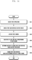
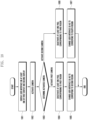
- An electronic device may include a first camera, a first display panel including multiple pixels and disposed to overlap, in at least a partial region thereof, a field-of-view region corresponding to a field of view of the first camera, and a processor, wherein the processor is configured to display a graphic user interface on the first display panel, sense activation of the first camera, deactivate at least one pixel, among the multiple pixels, corresponding to a first region which is at least a partial region of the first display panel, and change the graphic user interface so as to correspond to a second region on the first display panel, which is at least partially in contact with the first region.
- a method of changing a graphic user interface by an electronic device including a first camera and a first display panel disposed to overlap, in at least a partial region thereof, a field-of-view region corresponding to a field of view of the first camera, the first display panel including a first region which has a first transmittance, at least partially overlaps the first camera, and includes the field-of-view region, may include displaying a graphic user interface on the first display panel, sensing activation of the first camera, deactivating at least one pixel of the first display panel, corresponding to a first region, and changing the graphic user interface so as to correspond to a second region on the first display panel, which is at least partially in contact with the first region.
- usability may be improved by changing a user interface displayed on a screen according to the photographing mode of an electronic device including a UDC.
- regions on a display of an electronic device including a UDC may be used efficiently.
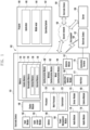
- Fig. 1 is a block diagram illustrating an electronic device 101 in a network environment 100 according to various embodiments.
- the electronic device 101 in the network environment 100 may communicate with an electronic device 102 via a first network 198 (e.g., a short-range wireless communication network), or at least one of an electronic device 104 or a server 108 via a second network 199 (e.g., a long-range wireless communication network).
- the electronic device 101 may communicate with the electronic device 104 via the server 108.
- the electronic device 101 may include a processor 120, memory 130, an input module 150, a sound output module 155, a display module 160, an audio module 170, a sensor module 176, an interface 177, a connecting terminal 178, a haptic module 179, a camera module 180, a power management module 188, a battery 189, a communication module 190, a subscriber identification module(SIM) 196, or an antenna module 197.
- at least one of the components e.g., the connecting terminal 178) may be omitted from the electronic device 101, or one or more other components may be added in the electronic device 101.
- some of the components e.g., the sensor module 176, the camera module 180, or the antenna module 197) may be implemented as a single component (e.g., the display module 160).
- the processor 120 may execute, for example, software (e.g., a program 140) to control at least one other component (e.g., a hardware or software component) of the electronic device 101 coupled with the processor 120, and may perform various data processing or computation. According to one embodiment, as at least part of the data processing or computation, the processor 120 may store a command or data received from another component (e.g., the sensor module 176 or the communication module 190) in volatile memory 132, process the command or the data stored in the volatile memory 132, and store resulting data in non-volatile memory 134.
- software e.g., a program 140
- the processor 120 may store a command or data received from another component (e.g., the sensor module 176 or the communication module 190) in volatile memory 132, process the command or the data stored in the volatile memory 132, and store resulting data in non-volatile memory 134.
- the processor 120 may include a main processor 121 (e.g., a central processing unit (CPU) or an application processor (AP)), or an auxiliary processor 123 (e.g., a graphics processing unit (GPU), a neural processing unit (NPU), an image signal processor (ISP), a sensor hub processor, or a communication processor (CP)) that is operable independently from, or in conjunction with, the main processor 121.
- a main processor 121 e.g., a central processing unit (CPU) or an application processor (AP)
- auxiliary processor 123 e.g., a graphics processing unit (GPU), a neural processing unit (NPU), an image signal processor (ISP), a sensor hub processor, or a communication processor (CP)
- the main processor 121 may be adapted to consume less power than the main processor 121, or to be specific to a specified function.
- the auxiliary processor 123 may be implemented as separate from, or as part of the main processor 121.
- the auxiliary processor 123 may control at least some of functions or states related to at least one component (e.g., the display module 160, the sensor module 176, or the communication module 190) among the components of the electronic device 101, instead of the main processor 121 while the main processor 121 is in an inactive (e.g., sleep) state, or together with the main processor 121 while the main processor 121 is in an active state (e.g., executing an application).
- the auxiliary processor 123 e.g., an image signal processor or a communication processor
- the auxiliary processor 123 may include a hardware structure specified for artificial intelligence model processing.
- An artificial intelligence model may be generated by machine learning. Such learning may be performed, e.g., by the electronic device 101 where the artificial intelligence is performed or via a separate server (e.g., the server 108). Learning algorithms may include, but are not limited to, e.g., supervised learning, unsupervised learning, semi-supervised learning, or reinforcement learning.
- the artificial intelligence model may include a plurality of artificial neural network layers.
- the artificial neural network may be a deep neural network (DNN), a convolutional neural network (CNN), a recurrent neural network (RNN), a restricted boltzmann machine (RBM), a deep belief network (DBN), a bidirectional recurrent deep neural network (BRDNN), deep Q-network or a combination of two or more thereof but is not limited thereto.
- the artificial intelligence model may, additionally or alternatively, include a software structure other than the hardware structure.
- the memory 130 may store various data used by at least one component (e.g., the processor 120 or the sensor module 176) of the electronic device 101.
- the various data may include, for example, software (e.g., the program 140) and input data or output data for a command related thererto.
- the memory 130 may include the volatile memory 132 or the non-volatile memory 134.
- the program 140 may be stored in the memory 130 as software, and may include, for example, an operating system (OS) 142, middleware 144, or an application 146.
- OS operating system
- middleware middleware
- application application
- the input module 150 may receive a command or data to be used by another component (e.g., the processor 120) of the electronic device 101, from the outside (e.g., a user) of the electronic device 101.
- the input module 150 may include, for example, a microphone, a mouse, a keyboard, a key (e.g., a button), or a digital pen (e.g., a stylus pen).
- the sound output module 155 may output sound signals to the outside of the electronic device 101.
- the sound output module 155 may include, for example, a speaker or a receiver.
- the speaker may be used for general purposes, such as playing multimedia or playing record.
- the receiver may be used for receiving incoming calls. According to an embodiment, the receiver may be implemented as separate from, or as part of the speaker.
- the display module 160 may visually provide information to the outside (e.g., a user) of the electronic device 101.
- the display module 160 may include, for example, a display, a hologram device, or a projector and control circuitry to control a corresponding one of the display, hologram device, and projector.
- the display module 160 may include a touch sensor adapted to detect a touch, or a pressure sensor adapted to measure the intensity of force incurred by the touch.
- the audio module 170 may convert a sound into an electrical signal and vice versa. According to an embodiment, the audio module 170 may obtain the sound via the input module 150, or output the sound via the sound output module 155 or a headphone of an external electronic device (e.g., an electronic device 102) directly (e.g., wiredly) or wirelessly coupled with the electronic device 101.
- an external electronic device e.g., an electronic device 102
- directly e.g., wiredly
- wirelessly e.g., wirelessly
- the sensor module 176 may detect an operational state (e.g., power or temperature) of the electronic device 101 or an environmental state (e.g., a state of a user) external to the electronic device 101, and then generate an electrical signal or data value corresponding to the detected state.
- the sensor module 176 may include, for example, a gesture sensor, a gyro sensor, an atmospheric pressure sensor, a magnetic sensor, an acceleration sensor, a grip sensor, a proximity sensor, a color sensor, an infrared (IR) sensor, a biometric sensor, a temperature sensor, a humidity sensor, or an illuminance sensor.
- the interface 177 may support one or more specified protocols to be used for the electronic device 101 to be coupled with the external electronic device (e.g., the electronic device 102) directly (e.g., wiredly) or wirelessly.
- the interface 177 may include, for example, a high definition multimedia interface (HDMI), a universal serial bus (USB) interface, a secure digital (SD) card interface, or an audio interface.
- HDMI high definition multimedia interface
- USB universal serial bus
- SD secure digital
- a connecting terminal 178 may include a connector via which the electronic device 101 may be physically connected with the external electronic device (e.g., the electronic device 102).
- the connecting terminal 178 may include, for example, a HDMI connector, a USB connector, a SD card connector, or an audio connector (e.g., a headphone connector).
- the haptic module 179 may convert an electrical signal into a mechanical stimulus (e.g., a vibration or a movement) or electrical stimulus which may be recognized by a user via his tactile sensation or kinesthetic sensation.
- the haptic module 179 may include, for example, a motor, a piezoelectric element, or an electric stimulator.
- the camera module 180 may capture a still image or moving images.
- the camera module 180 may include one or more lenses, image sensors, image signal processors, or flashes.
- the power management module 188 may manage power supplied to the electronic device 101.
- the power management module 188 may be implemented as at least part of, for example, a power management integrated circuit (PMIC).
- PMIC power management integrated circuit
- the battery 189 may supply power to at least one component of the electronic device 101.
- the battery 189 may include, for example, a primary cell which is not rechargeable, a secondary cell which is rechargeable, or a fuel cell.
- the communication module 190 may support establishing a direct (e.g., wired) communication channel or a wireless communication channel between the electronic device 101 and the external electronic device (e.g., the electronic device 102, the electronic device 104, or the server 108) and performing communication via the established communication channel.
- the communication module 190 may include one or more communication processors that are operable independently from the processor 120 (e.g., the application processor (AP)) and supports a direct (e.g., wired) communication or a wireless communication.
- AP application processor
- the communication module 190 may include a wireless communication module 192 (e.g., a cellular communication module, a short-range wireless communication module, or a global navigation satellite system (GNSS) communication module) or a wired communication module 194 (e.g., a local area network (LAN) communication module or a power line communication (PLC) module).
- a wireless communication module 192 e.g., a cellular communication module, a short-range wireless communication module, or a global navigation satellite system (GNSS) communication module
- GNSS global navigation satellite system
- wired communication module 194 e.g., a local area network (LAN) communication module or a power line communication (PLC) module.
- LAN local area network
- PLC power line communication
- a corresponding one of these communication modules may communicate with the external electronic device via the first network 198 (e.g., a short-range communication network, such as BluetoothTM, wireless-fidelity (Wi-Fi) direct, or infrared data association (IrDA)) or the second network 199 (e.g., a long-range communication network, such as a legacy cellular network, a 5G network, a next-generation communication network, the Internet, or a computer network (e.g., LAN or wide area network (WAN)).
- first network 198 e.g., a short-range communication network, such as BluetoothTM, wireless-fidelity (Wi-Fi) direct, or infrared data association (IrDA)
- the second network 199 e.g., a long-range communication network, such as a legacy cellular network, a 5G network, a next-generation communication network, the Internet, or a computer network (e.g., LAN or wide area network (WAN)).
- the wireless communication module 192 may identify and authenticate the electronic device 101 in a communication network, such as the first network 198 or the second network 199, using subscriber information (e.g., international mobile subscriber identity (IMSI)) stored in the subscriber identification module 196.
- subscriber information e.g., international mobile subscriber identity (IMSI)
- the wireless communication module 192 may support a 5G network, after a 4G network, and next-generation communication technology, e.g., new radio (NR) access technology.
- the NR access technology may support enhanced mobile broadband (eMBB), massive machine type communications (mMTC), or ultra-reliable and low-latency communications (URLLC).
- eMBB enhanced mobile broadband
- mMTC massive machine type communications
- URLLC ultra-reliable and low-latency communications
- the wireless communication module 192 may support a high-frequency band (e.g., the mmWave band) to achieve, e.g., a high data transmission rate.
- the wireless communication module 192 may support various technologies for securing performance on a high-frequency band, such as, e.g., beamforming, massive multiple-input and multiple-output (massive MIMO), full dimensional MIMO (FD-MIMO), array antenna, analog beam-forming, or large scale antenna.
- the wireless communication module 192 may support various requirements specified in the electronic device 101, an external electronic device (e.g., the electronic device 104), or a network system (e.g., the second network 199).
- the wireless communication module 192 may support a peak data rate (e.g., 20Gbps or more) for implementing eMBB, loss coverage (e.g., 164dB or less) for implementing mMTC, or U-plane latency (e.g., 0.5ms or less for each of downlink (DL) and uplink (UL), or a round trip of 1ms or less) for implementing URLLC.
- a peak data rate e.g., 20Gbps or more
- loss coverage e.g., 164dB or less
- U-plane latency e.g., 0.5ms or less for each of downlink (DL) and uplink (UL), or a round trip of 1ms or less
- the antenna module 197 may transmit or receive a signal or power to or from the outside (e.g., the external electronic device) of the electronic device 101.
- the antenna module 197 may include an antenna including a radiating element composed of a conductive material or a conductive pattern formed in or on a substrate (e.g., a printed circuit board (PCB)).
- the antenna module 197 may include a plurality of antennas (e.g., array antennas). In such a case, at least one antenna appropriate for a communication scheme used in the communication network, such as the first network 198 or the second network 199, may be selected, for example, by the communication module 190 (e.g., the wireless communication module 192) from the plurality of antennas.
- the signal or the power may then be transmitted or received between the communication module 190 and the external electronic device via the selected at least one antenna.
- another component e.g., a radio frequency integrated circuit (RFIC)
- RFIC radio frequency integrated circuit
- the antenna module 197 may form a mmWave antenna module.
- the mmWave antenna module may include a printed circuit board, a RFIC disposed on a first surface (e.g., the bottom surface) of the printed circuit board, or adj acent to the first surface and capable of supporting a designated high-frequency band (e.g., the mmWave band), and a plurality of antennas (e.g., array antennas) disposed on a second surface (e.g., the top or a side surface) of the printed circuit board, or adj acent to the second surface and capable of transmitting or receiving signals of the designated high-frequency band.
- a RFIC disposed on a first surface (e.g., the bottom surface) of the printed circuit board, or adj acent to the first surface and capable of supporting a designated high-frequency band (e.g., the mmWave band)
- a plurality of antennas e.g., array antennas
- At least some of the above-described components may be coupled mutually and communicate signals (e.g., commands or data) therebetween via an inter-peripheral communication scheme (e.g., a bus, general purpose input and output (GPIO), serial peripheral interface (SPI), or mobile industry processor interface (MIPI)).
- an inter-peripheral communication scheme e.g., a bus, general purpose input and output (GPIO), serial peripheral interface (SPI), or mobile industry processor interface (MIPI)
- commands or data may be transmitted or received between the electronic device 101 and the external electronic device 104 via the server 108 coupled with the second network 199.
- Each of the electronic devices 102 or 104 may be a device of a same type as, or a different type, from the electronic device 101.
- all or some of operations to be executed at the electronic device 101 may be executed at one or more of the external electronic devices 102, 104, or 108. For example, if the electronic device 101 should perform a function or a service automatically, or in response to a request from a user or another device, the electronic device 101, instead of, or in addition to, executing the function or the service, may request the one or more external electronic devices to perform at least part of the function or the service.
- the one or more external electronic devices receiving the request may perform the at least part of the function or the service requested, or an additional function or an additional service related to the request, and transfer an outcome of the performing to the electronic device 101.
- the electronic device 101 may provide the outcome, with or without further processing of the outcome, as at least part of a reply to the request.
- a cloud computing, distributed computing, mobile edge computing (MEC), or client-server computing technology may be used, for example.
- the electronic device 101 may provide ultra low-latency services using, e.g., distributed computing or mobile edge computing.
- the external electronic device 104 may include an internet-of things (IoT) device.
- the server 108 may be an intelligent server using machine learning and/or a neural network.
- the external electronic device 104 or the server 108 may be included in the second network 199.
- the electronic device 101 may be applied to intelligent services (e.g., smart home, smart city, smart car, or healthcare) based on 5G communication technology or IoT-related technology.
- FIG. 2A is a perspective view of the front surface of an electronic device 200 (e.g., a mobile electronic device) according to various embodiments.
- FIG. 2B is a perspective view of the rear surface of the electronic device 200 in FIG. 2A according to various embodiments.
- the electronic device 200 may include a housing 210 including a first surface (or a front surface) 210A, a second surface (or a rear surface) 210B, and a side surface 210C surrounding a space between the first surface 210A and the second surface 210B.
- a housing may indicate a structure forming some of the first surface 210A, the second surface 210B, and the side surface 210C in FIG. 2A .
- the first surface 210A may be formed of a front plate 202 (e.g., a polymer plate or a glass plate including various coated layers), at least a part of which is substantially transparent.
- the second surface 210B may be formed of a rear plate 211 which is substantially opaque.
- the rear plate 211 may be formed of, for example, coated or colored glass, ceramic, polymer, metal (e.g., aluminum, stainless steel (STS), or magnesium), or a combination of at least two of the materials.
- the side surface 210C may be coupled to the front plate 202 and the rear plate 211, and may be formed of a side bezel structure 218 (or a "side member") containing metal and/or polymer.
- the rear plate 211 and the side bezel structure 218 may be integrally formed, and may include an identical material (e.g., a metal material, such as aluminum).
- the front plate 202 may include a first region 210D, curved and seamlessly extending from the first surface 210A toward the rear plate, at each of both ends of a long edge of the front plate.
- the rear plate 211 may include a second region 210E, curved and seamlessly extending from the second surface 210B toward the front plate, at each of both ends of a long edge thereof.
- the front plate 202 or the rear plate 211 may include only one of the first region 201D or the second region 201E.
- the front plate 202 may include only a flat surface disposed parallel to the second surface 210B without including the first region and the second region.
- the side bezel structure 218 may have a first thickness (or width) at a side surface which does not include the first region 210D or the second region 210E, as described above, and may have a second thickness less than the first thickness at a side surface which includes the first region 210D or the second region 210E.
- the electronic device 200 may include at least one among a display 400, an input device 203, sound output devices 207 and 214, sensor modules 204 and 219, camera modules 205 and 212, key input devices 217, an indicator (not shown), and a connector 208.
- the electronic device 200 may omit at least one (e.g., the key input devices 217 or the indicator) of the elements, or may additionally include another element.
- the display 400 may be visually exposed through a considerable part of the front plate 202. In an embodiment, at least a part of the display 400 may be exposed through the front plate 202 which forms the first surface 210A, and the first region 201D of the side surface 210C.
- the display 400 may be coupled to or disposed adjacent to a touch sensing circuit, a pressure sensor capable of measuring the strength (pressure) of a touch, and/or a digitizer for detecting a magnetic field-type stylus pen.
- at least some of the sensor modules 204 and 219 and/or at least some of the key input devices 217 may be disposed in the first region 201D and/or the second region 201E.
- the input device 203 may include a microphone 203.
- the input device 203 may include multiple microphones 203 disposed so as to sense the direction of a sound.
- the sound output devices 207 and 214 may include speakers 207 and 214.
- the speakers 207 and 214 may include an external speaker 207 and a call receiver 214.
- at least some of the microphone 203, the speakers 207 and 214, and the connector 208 may be disposed in the inner space of the electronic device 200, and may be exposed to an outside environment through at least one hole formed in the housing 210.
- the hole formed in the housing 210 may be commonly used for the microphone 203 and the speakers 207 and 214.
- the sound output devices 207 and 214 may include a speaker (e.g., a piezo speaker) operating without the hole formed in the housing 210.
- the sensor modules 204 and 219 may generate electrical signals or data values corresponding to an operation state inside the electronic device 200 or an environment state outside the electronic device 200.
- the sensor modules 204 and 219 may include, for example, a first sensor module 204 (e.g., a proximity sensor) and/or a second sensor module (not shown) (e.g., a fingerprint sensor), disposed in the first surface 210A of the housing 210, and/or a third sensor module 219 (e.g., an HRM sensor) disposed in the second surface 210B of the housing 210.
- a first sensor module 204 e.g., a proximity sensor
- a second sensor module not shown
- a third sensor module 219 e.g., an HRM sensor
- the fingerprint sensor may be disposed under the first surface 210A (e.g., a home key button) of the housing 210, a partial region of the second surface 210B, and/or the display 400.
- the electronic device 200 may further include at least one among unillustrated sensor modules, for example, a gesture sensor, a gyro sensor, a barometric pressure sensor, a magnetic sensor, an acceleration sensor, a grip sensor, a color sensor, an infrared (IR) sensor, a biosensor, a temperature sensor, a humidity sensor, a proximity sensor, or an illumination sensor.
- a gesture sensor e.g., a gyro sensor, a barometric pressure sensor, a magnetic sensor, an acceleration sensor, a grip sensor, a color sensor, an infrared (IR) sensor, a biosensor, a temperature sensor, a humidity sensor, a proximity sensor, or an illumination sensor.
- IR infrared
- the camera modules 205 and 212 may include a first camera module 205 disposed in the first surface 210A of the electronic device 200, a second camera module 212 disposed in the second surface 210B, and/or a flash 213.
- the camera modules 205 and 212 may include one lens or multiple lenses, an image sensor, and/or an image signal processor.
- the flash 213 may include, for example, a light-emitting diode or a xenon lamp.
- at least two lenses (a wide-angle lens, an ultra-wide-angle lens, or a telephoto lens) and image sensors may be disposed in one surface of the electronic device 200.
- the key input devices 217 may be disposed in the side surface 210C of the housing 210.
- the electronic device 200 may not include some or all of the above-mentioned key input devices 217, and key input devices 217, which are not included, may be implemented in other forms, such as soft keys, on the display 400.
- the key input devices 217 may be implemented by using pressure sensors included in the display 400.
- the indicator may be disposed, for example, in the first surface 210A of the housing 210.
- the indicator may provide, for example, state information of the electronic device 200 in the form of light (e.g., a light-emitting element).
- the light-emitting element may provide, for example, a light source operating in conjunction with the operation of the first camera module 205.
- the indicator may include, for example, an LED, an IR LED and/or a xenon lamp.
- the connector hole 208 may include a first connector hole 208 capable of receiving a connector (e.g., a universal serial bus (USB) connector) for transmitting or receiving power and/or data to or from an external electronic device, and/or a second connector hole (or an earphone hole) (not shown) capable of receiving a connector for transmitting or receiving an audio signal to or from the external electronic device.
- a connector e.g., a universal serial bus (USB) connector
- USB universal serial bus
- Some camera modules 205 of the camera modules 205 and 212, some sensor modules 204 among the sensor modules 204 and 219, or the indicator may be disposed to be exposed through the display 400.
- the first camera module 205, the first sensor modules 204, or the indicator may be disposed in the inner space of the electronic device 200 so as to be exposed to an external environment through an opening bored in the display 400 up to the front plate, or through a transmissive region of the display 400.
- a region in which the display 400 faces the first camera module 205 is a part of a region in which contents are displayed, and may be formed as a transmissive region having a predetermined transmittance.
- the transmissive region may be formed to have a transmittance ranging from about 5% to about 20%.
- This transmissive region may include a region overlapping an effective aperture (e.g., a field of view) of the first camera module 205, through which light that is imaged by an image sensor to produce an image passes.
- the transmissive region of the display 400 may include a region having a pixel density lower than that therearound.
- the transmissive region may replace the opening.
- the first camera module 205 may include an under-display camera (UDC).
- UDC under-display camera
- some sensor modules 204 may be disposed in the inner space of the electronic device so as to perform functions thereof without being visually exposed through the front plate 202. For example, in this case, a region of the display 400, which faces the sensor module, may not require a bored opening.
- the electronic device 200 has a bar-type or plate-type exterior, but the disclosure is not limited thereto.
- the illustrated electronic device 200 may be a part of a foldable electronic device, a slidable electronic device, a stretchable electronic device, and/or a rollable electronic device.
- the "foldable electronic device”, the “slidable electronic device”, the “stretchable electronic device”, and/or the “rollable electronic device” may imply an electronic device wherein, because the bending deformation of a display (e.g., the display 400 in FIG.
- a part of the display may be folded or may be wound or rolled, or the region of the display may be at least partially enlarged and/or received into a housing (e.g., the housing 210 in FIGS. 2A and 2B ).
- a screen display region may be extended and used by unfolding a display or exposing the wider area of the display to the outside according to a user's need.
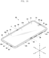
- FIG. 3A is a front perspective view illustrating a flat state or an unfolding state) of an electronic device including a second form according to various embodiments.
- FIG. 3B is a plan view illustrating the front surface of an electronic device in the unfolded state in FIG. 3A according to various embodiments.
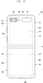
- FIG. 3C is a plan view illustrating the rear surface of an electronic device in the unfolded state in FIG. 3A according to various embodiments.
- the electronic device 300 may include a pair of housings 310 and 320 (e.g., foldable housings) rotatably coupled to each other so as to be folded while facing each other with reference to a hinge device (e.g., the hinge device 340 in FIG. 3B ).
- the hinge device e.g., the hinge device 340 in FIG. 3B
- the hinge device may be disposed in the X-axis direction or may be disposed in the Y-axis direction.
- at least two hinge devices e.g., the hinge device 340 in FIG. 3B
- the electronic device 300 may include a flexible display 400 (e.g., a foldable display) disposed in a region formed by the pair of housings 310 and 320.
- a first housing 310 and a second housing 320 may be disposed at both sides with reference to a folding axis (axis A), and may have shapes substantially symmetric with respect to the folding axis (axis A).
- the angle or the distance between the first housing 310 and the second housing 320 may vary depending on whether the state of the electronic device 300 is an unfolded state (a flat state or unfolding state), a folded state (a folding state), or an intermediate state.
- the pair of housings 310 and 320 may include the first housing 310 (e.g., a first housing structure) coupled to the hinge device (e.g., the hinge device 340 in FIG. 3B ) and the second housing 320 (e.g., a second housing structure) coupled to the hinge device (e.g., the hinge device 340 in FIG. 3B ).
- the first housing 310 in an unfolded state, may include a first surface 311 facing a first direction (e.g., a forward direction) (the z-axis direction) and a second surface 312 opposite to the first surface 311 and facing a second direction (e.g., a backward direction) (-z-axis direction).
- the second housing 320 in the unfolded state, may include a third surface 321 facing a first direction (the z-axis direction) and a fourth surface 322 facing a second direction (-z-axis direction).
- the electronic device 300 may operate in such a manner that the first surface 311 of the first housing 310 and the third surface 321 of the second housing 320 face a substantially identical first direction (the z-axis direction) in the unfolded state and that the first surface 311 and the third surface 321 face each other in the folded state.
- the electronic device 300 may operate in such a manner that the second surface 312 of the first housing 310 and the fourth surface 322 of the second housing 320 face a substantially identical second direction (the - z-axis direction) in the unfolded state and that the second surface 312 and the fourth surface 322 face directions opposite to each other in the folded state.
- the second surface 312 may face the first direction (the z-axis direction)
- the fourth surface 322 may face the second direction (the - z-axis direction).
- the first housing 310 may include a first side member 313 at least partially forming the exterior of the electronic device 300 and a first rear cover 314 coupled to the first side member 313 and forming at least a part of the second surface 312 of the electronic device 300.
- the first side member 313 may include a first side surface 313a, a second side surface 313b extending from one end of the first side surface 313a, and a third side surface 313c extending from the other end of the first side surface 313a.
- the first side member 313 may be formed in a right-angled tetragonal (e.g., square or rectangular) shape through the first side surface 313a, the second side surface 313b, and the third side surface 313c.
- the second housing 320 may include a second side member 323 at least partially forming the exterior of the electronic device 300, and a second rear cover 324 coupled to the second side member 323 and forming at least a part of the fourth surface 322 of the electronic device 300.
- the second side member 323 may include a fourth side surface 323a, a fifth side surface 323b extending from one end of the fourth side surface 323a, and a sixth side surface 323c extending from the other end of the fourth side surface 323a.
- the second side member 323 may be formed in a right-angled tetragonal shape through the fourth side surface 323a, the fifth side surface 323b, and the sixth side surface 323c.
- the pair of housings 310 and 320 are not limited to the illustrated form and coupling, and may be implemented by other shapes or a combination and/or coupling of other components.
- the first side member 313 may be formed integrally with the first rear cover 314, and the second side member 323 may be formed integrally with the second rear cover 324.
- the second side surface 313b of the first side member 313 and the fifth side surface 323b of the second side member 323 may be connected to each other without any gap therebetween.
- the third side surface 313c of the first side member 313 and the sixth side surface 323c of the second side member 323 may be connected to each other without any gap therebetween.
- a length obtained by summing the second side surface 313b and the fifth side surface 323b may be configured to be greater than the length of the first side surface 313a and/or the fourth side surface 323a.
- a length obtained by summing the third side surface 313c and the sixth side surface 323c may be configured to be greater than the length of the first side surface 313a and/or the fourth side surface 323a.
- the first rear cover 314 and/or the second rear cover 324 may be formed of at least one or a combination of at least two among, for example, coated or colored glass, ceramic, polymer, or metal (e.g., aluminum, stainless steel (STS), or magnesium).
- coated or colored glass ceramic, polymer, or metal (e.g., aluminum, stainless steel (STS), or magnesium).
- metal e.g., aluminum, stainless steel (STS), or magnesium
- the flexible display 400 may be disposed to extend from the first surface 311 of the first housing 310 to at least a part of the third surface 321 of the second housing 320 via the hinge device (e.g., the hinge device 340 in FIG. 3B ).
- the flexible display 400 may include a first part 330a substantially corresponding to the first surface 311, a second part 330b corresponding to the third surface 321, and a third part 330c (e.g., a bendable region) connecting the first part 330a to the second part 330b and corresponding to the hinge device (e.g., the hinge device 340 in FIG. 3B ).
- the electronic device 300 may include a first protective cover 315 (e.g., a first protective frame or a first decoration member) coupled along the edge of the first housing 310.
- the electronic device 300 may include a second protective cover 325 (e.g., a second protective frame or a second decoration member) coupled along the edge of the second housing 320.
- the first protective cover 315 and/or the second protective cover 325 may be formed of a metal or polymer material.
- the first protective cover 315 and/or the second protective cover 325 may be used as decoration members.
- the flexible display 400 may be positioned such that the edge of the first part 330a is interposed between the first housing 310 and the first protective cover 315. According to an embodiment, the flexible display 400 may be positioned such that the edge of the second part 330b is interposed between the second housing 320 and the second protective cover 325. According to an embodiment, the flexible display 400 may be positioned such that the edge of the flexible display 400, corresponding to a protective cap 335 disposed in a region corresponding to the hinge device (e.g., the hinge device 340 in FIG. 3B ), is protected through the protective cap. Therefore, the edge of the flexible display 400 may be substantially protected from the outside.
- the electronic device 300 may include a hinge housing 341 (e.g., a hinge cover) disposed to support the hinge device (e.g., the hinge device 340 in FIG. 3B ), be exposed outside when the electronic device 300 is in a folded state, and be moved into a first space (e.g., in the inner space of the first housing 310) and a second space (e.g., the inner space of the second housing 320) when the electronic device 300 is in an unfolded state and thus be not viewed from outside.
- the flexible display 400 may be disposed to extend from at least a part of the second surface 312 to at least a part of the fourth surface 322. In this case, the electronic device 300 may be folded such that the flexible display 400 is exposed outside (an out-folding method).
- the electronic device 300 may include a sub-display 331 disposed separately from the flexible display 400.
- the sub-display 331 may be disposed to be at least partially disposed on the second surface 312 of the first housing 310, and thus, in the folded state, may display state information of the electronic device 300 replacing a display function of the flexible display 400.
- the sub-display 331 may be disposed so as to be viewed from outside through at least a partial region of the first rear cover 314.
- the sub-display 331 may be disposed on the fourth surface 322 of the second housing 320. In this case, the sub-display 331 may be disposed so as to be exposed from outside through at least a partial region of the second rear cover 324.
- the electronic device 300 may include at least one among an input device 303 (e.g., a microphone), sound output devices 301 and 302, sensor modules 304, camera devices 305 and 308, key input devices 306, or a connector port 307.
- the input device 303 e.g., the microphone
- the sound output devices 301 and 302, the sensor modules 304, the camera devices 305 and 308, the key input devices 306, or the connector port 307 may indicate a hole or a shape formed in the first housing 310 or the second housing 320, but may be defined as including a substantial electronic component which is disposed in the electronic device 300 and operates through a hole or a shape (e.g., the input device, the sound output device, the sensor module, or the camera device).
- the input device 303 may include at least one microphone 303 disposed in the second housing 320.
- the input device 303 may include multiple microphones 303 disposed to sense the direction of a sound.
- the multiple microphones 303 may be disposed in appropriate positions at the first housing 310 and/or the second housing 320.
- the sound output devices 301 and 302 may include speakers 301 and 302.
- the speakers 301 and 302 may include a call receiver 301 disposed at the first housing 310 and a speaker 302 disposed at the second housing 320.
- the input device 303, the sound output devices 301 and 302, and the connector port 307 may be disposed in a space provided in the first housing 310 and/or the second housing 320 of the electronic device 300, and may be exposed to an external environment through at least one hole formed in the first housing 310 and/or the second housing 320.
- at least one connector port 307 may be used to transmit or receive power and/or data to or from an external electronic device.
- at least one connector port e.g., an earphone jack hole
- may receive a connector e.g., an earphone jack for transmitting or receiving an audio signal to or from an external electronic device.
- holes formed in the first housing 310 and/or the second housing 320 may be commonly used for the input device 303 and the sound output devices 301 and 302.
- the sound output devices 301 and 302 may include a speaker (e.g., a piezo speaker) operating without holes formed in the first housing 310 and/or the second housing 320.
- the sensor modules 304 may generate electrical signals or data values corresponding to an operation state inside the electronic device 300 or an environment state outside the electronic device 300.
- the sensor modules 304 may detect an external environment through, for example, the first surface 311 of the first housing 310.
- the electronic device 300 may further include at least one sensor module disposed to detect an external environment through the second surface 312 of the first housing 310.
- the sensor modules 304 e.g., an illumination sensor
- the sensor modules 304 may include at least one among a gesture sensor, a gyro sensor, a barometric pressure sensor, a magnetic sensor, an acceleration sensor, a grip sensor, a color sensor, an infrared (IR) sensor, a biosensor, a temperature sensor, a humidity sensor, an illumination sensor, a proximity sensor, or an ultrasonic sensor.
- the camera devices 305 and 308 may include a first camera device 305 (e.g., a front camera device) disposed in the first surface 311 of the first housing 310, and a second camera device 308 disposed in the second surface 312 of the first housing 310.
- the electronic device 300 may further include a flash 309 disposed near the second camera device 308.
- the camera devices 305 and 308 may include one or multiple lenses, an image sensor, and/or an image signal processor.
- the flash 309 may include, for example, a light-emitting diode or a xenon lamp.
- the camera devices 305 and 308 may be disposed such that at least two lenses (a wide-angle lens, an ultra-wide-angle lens, or a telephoto lens) and image sensors are positioned in one surface (e.g., the first surface 311, the second surface 312, the third surface 321, or the fourth surface 322) of the electronic device 300.
- the camera devices 305 and 308 may also include an image sensor and/or lenses for time of flight (TOF).
- TOF time of flight
- the key input devices 306 may be disposed in the third side surface 313c of the first side member 313 of the first housing 310.
- the key input devices 306 may also be disposed in at least one side surface among the other side surfaces 313a and 313b of the first housing 310 and/or side surfaces 323a, 323b, and 323c of the second housing 320.
- the electronic device 300 may not include some or all of the key input devices 306, and key input devices 306, which are not included, may be implemented in other forms, such as soft keys, on the flexible display 400.
- the key input devices 306 may also be implemented using pressure sensors included in the flexible display 400.
- some camera devices e.g., the first camera device 305) of the camera devices 305 and 308 or the sensor modules 304 may be disposed to be exposed through the flexible display 400.
- the first camera device 305 or the sensor modules 304 may be disposed in the inner space of the electronic device 300 so as to be exposed to an external environment through an opening (e.g., a through-hole) at least partially formed in the flexible display 400.
- some sensor modules 304 may also be disposed in the inner space of the electronic device 300 so as to perform functions thereof without being visually exposed through the flexible display 400.
- a region of the flexible display 400, facing the sensor modules may not require an opening.
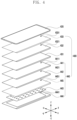
- FIG. 4 is an exploded perspective view of a display 400 according to various embodiments.
- the display 400 in FIG. 4 may be at least partially similar to the display module 160 in FIG. 1 , or may further include another embodiment of a display.
- the display 400 may include a polarizer (POL)(432) (e.g., a polarizing film or a polarizing layer), a display panel 431, and at least one subsidiary material layer 440 attached to the rear surface of the display panel 431, which are sequentially disposed on the rear surface of a front cover 420 (e.g., a front plate, a glass plate, a first cover member, or a cover member) through an adhesive member (e.g., an adhesive member 410 in FIG. 5A ).
- the adhesive member 410 may include an optical clear adhesive (OCA), a pressure sensitive adhesive (PSA), a thermo-responsive adhesive, a normal adhesive, or a double-sided tape.
- the display panel 431 and the POL 432 may be integrally formed.
- the display 400 may include a control circuit (not shown).
- the control circuit may include a flexible printed circuit board (FPCB) configured to electrically connect a main printed circuit board of an electronic device (e.g., the electronic device 200 in FIG. 2A ) to the display panel 431, and a display driver IC (DDI) mounted on the FPCB.
- the display 400 may additionally include a touch panel 433.
- the control circuit may include a touch display driver IC (TDDI).
- the display 400 may include a fingerprint sensor (not shown) disposed near the control circuit.
- the fingerprint sensor may include an ultrasonic or optical fingerprint sensor capable of recognizing a fingerprint of a finger which touches or approaches the outer surface of the front cover 420 through holes at least partially formed in some of the elements of the display 400.
- the at least one subsidiary material layer 440 may include at least one polymer member 441 or 442 disposed on the rear surface of the display panel 431, at least one functional member 443 disposed on the rear surface of the at least one polymer member 441 or 442, and a conductive member 444 disposed on the rear surface of the at least one functional member 443.
- the at least one polymer member 441 or 442 may include a light-blocking layer 441 (e.g., a black layer including uneven patterns) for removing bubbles generated between the display panel 431 and attachments thereunder and blocking light generated in the display panel 431 or light entering from the outside and/or a buffer layer 442 disposed to moderate an impact.
- the at least one functional member 443 may include a heat dissipation sheet (e.g., a graphite sheet) for heat dissipation, an added display, a force touch FPCB, a fingerprint sensor FPCB, an antenna radiator of communication, a conductive/nonconductive tape, or an open cell sponge.
- the conductive member 444 which is metal plate, may contribute to reinforcement of the rigidity of an electronic device (e.g., the electronic device 200 in FIG. 2 ), and may be used to shield ambient noise and dissipate heat emitted from ambient heat-emitting components.
- the conductive member 444 may include Cu, Al, Mg, SUS, or CLAD (e.g., a lamination member in which SUS and Al are alternately disposed).
- the display 400 may further include a detection member 445 for detecting an input by an electromagnetic induction type writing member (e.g., an electronic pen).
- the detection member 445 may include a digitizer.
- the detection member 445 may be disposed between the at least one polymer member 442 and the functional member 443.
- the detection member 445 may also be disposed between the display panel 431 and the at least one polymer member 441.
- the detection member 445 may be disposed on the rear surface of the conductive member 444.
- the subsidiary material layer 440 may include openings 4411, 4421, 4451, and 4441 formed in positions corresponding to a camera module (e.g., a camera module 500 in FIG. 5A ).
- the camera module 500 may be disposed close to the rear surface of the display panel 431 through openings 4411, 4421, 4451, and 4441.
- the POL 432 or the touch panel 433 disposed on the display panel 431 may also include an opening 4321 or 4331 formed therethrough at a corresponding position in order to prevent the degradation of performance of the camera module 500 due to a refractive index.
- the POL 432 and/or the touch panel 433 may be transparently processed, or polarization characteristics may be removed.
- layers with no opening e.g., the display panel 431) and/or the touch panel 433 may include a coated layer capable of performing index matching in order to minimize a refractive index difference.
- the display 400 may include an organic light emitting diode (OLED) display or a liquid crystal display (LCD).
- FIG. 5A is a partial cross-sectional view of the electronic device 200, taken along line 5-5 in FIG. 2A according to various embodiments.
- the description is made by using an unbreakable (UB) type OLED display (e.g., a curved display) as an example, but is not limited thereto.
- UB unbreakable
- the description may be applied to a flat type display of an on-cell touch active matrix organic light-emitting diode (AMOLED) (OCTA) scheme.
- AMOLED organic light-emitting diode
- the electronic device 200 may include a front cover 420 (e.g., a cover member, a front plate, a front window, or a first plate) facing a first direction (the z-axis direction), a rear cover 680 (e.g., a rear cover member, a rear plate, a rear window, or a second plate) facing a direction opposite to the direction faced by the front cover 420, and a side member 610 surrounding a space 2001 between the front cover 420 and the rear cover 680.
- the electronic device 200 may include a first waterproof member 4201 disposed between a subsidiary material layer 440 of a display 400 and the side member 610.
- the electronic device 200 may include a second waterproof member 6801 disposed between the side member 610 and the rear cover 680.
- the first waterproof member 4201 and the second waterproof member 6801 may prevent outside foreign matter or water from being introduced into the inner space 2001 of the electronic device 200.
- a waterproof member may be disposed in at least a part of a mounting support structure between a camera module 500 and the side member 610.
- the first waterproof member 4201 and/or the second waterproof member 6801 may be replaced with an adhesive member.
- the side member 610 may further include a first support member 611 which at least partially extends into the inner space 2001 of the electronic device 200.
- the first support member 611 may be formed by a structural coupling with the side member 610.
- the first support member 611 may support the camera module 500 such that the camera module 500 is aligned and disposed near the rear surface of a display panel 431 through an opening (e.g., an opening (OP) in FIG. 5B ) of the subsidiary material layer 440 of the display 400.
- the camera module 500 may include a camera housing 510, a lens housing 520 disposed in an inner space 5101 of the camera housing 510 and at least partially protruding in a display direction (e.g., the z-axis direction), multiple lenses 530 (531, 532, 533, and 534) aligned at regular intervals in an inner space 5201 of the lens housing 520, and at least one image sensor 540 disposed in the inner space 5101 of the camera housing 510 so as to acquire at least a part of light having passed through the multiple lenses 530.
- a display direction e.g., the z-axis direction
- the lens housing 520 may move through a predetermined driving unit in the camera housing 510 such that the distance to the display panel 431 varies.
- a separate driving unit may be disposed such that the camera module 500 changes the position of at least one of the multiple lenses 530 in order to perform the AF function.
- the camera housing 510 may be omitted, and the lens housing 520 may be directly disposed at the first support member 611 through a predetermined alignment process.
- the camera housing 510 when the lens housing 520 is directly disposed at the first support member 611, the camera housing 510 may be omitted in order to reduce a camera arrangement space, and the lens housing 520 may be disposed to be attached to one side surface of the first support member 611.
- the camera module 500 may be aligned through a through-hole 601 of the first support member 611, and then may be attached to the rear surface of the first support member 611 by an adhesive member 612 (e.g., a bonding member or a tape member).
- the display 400 may include a touch panel (e.g., the touch panel 433 in FIG. 4 ), a POL 432, a display panel 431, a light-blocking layer 441, a buffer layer (e.g., the buffer layer 442 in FIG. 4 ), a digitizer (e.g., the detection member 445 in FIG. 4 ), a functional member (e.g., the functional member 443 in FIG. 4 ), and/or a conductive member (e.g., the conductive member 444 in FIG. 4 ).
- the camera module 500 may be supported by a second support member 660 (e.g., a rear case) additionally disposed in the inner space of the electronic device.
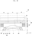
- FIG. 5B is an enlarged view of region 6 in FIG. 5A according to various embodiments.
- the electronic device 200 may include an adhesive member 410, the POL 432, the display panel 431, and the subsidiary material layer 440, which are disposed between the rear surface of the front cover 420 and the side member 610.
- the POL 432 may include an opening 4321 formed in order to improve an optical transmittance of the camera module 500.
- a part corresponding to the opening 4321 may be at least partially omitted.
- the opening 4321 formed in the POL 432 may be filled with an index material for adjusting the refractive index according to an increase in interfacial reflection.
- the POL 432 may be omitted, and may also be replaced with a color filter layer including a color filter and a black mask in the corresponding position thereof.
- the color filter layer may also include an opening in order to improve an optical transmittance of the camera module.
- a region of the POL 432 corresponding to the multiple lenses 530 may be formed to have a high transmittance without having the opening 4321 formed therethrough.
- at least a partial region of the POL 432 e.g., a region corresponding to the multiple lenses 530
- a member (not shown) for increasing a transmittance may be disposed on at least a part (e.g., an upper side surface or a lower side surface) of the region of the POL 432 corresponding to the multiple lenses 530.
- the subsidiary material layer 440 may include an opening (OP) formed in a region at least partially overlapping the multiple lenses 530.
- the opening (OP) formed in the subsidiary material layer 440 may be formed as one opening (OP) by overlapping an opening (e.g., the opening 4411 in FIG. 4 ) formed in a light-blocking layer 441, an opening (e.g., the opening 4421 in FIG. 4 ) formed in the buffer layer 442, an opening (e.g., the opening 4431 in FIG. 4 ) formed in the functional member 443, and an opening (e.g., the opening 4441 in FIG. 4 ) formed in the conductive member 444.
- the openings may have different sizes so as to correspond to the shape of the camera module 500.
- the display panel 431 may include a first region A1, which overlaps an effective aperture of the camera module 500, and a second region A2 surrounding the first region A1.
- the first region A1 may be formed to have a light transmittance required by the camera module 500 through adjustment of a pixel density and/or a wiring density.
- the second region A2 may include a normal active region of the display panel 431.
- the second region A2 may be a region in which a light transmittance for the camera module 500 has not been taken into account.
- the display panel 431 may include first multiple pixels (e.g., P in FIG.
- the wiring density of the first region A1 may be formed to be lower than the wiring density of the second region A2, thereby contributing to transmittance improvement.
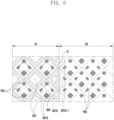
- FIG. 6 illustrates a partial configuration of a display panel when region 7 in FIG. 5B according to various embodiments of the disclosure is seen from above.
- the display panel when the display 400 is seen from above, the display panel may include a first region A1 overlapping an effective aperture of the camera module 500, and a second region A2 surrounding the first region A1.
- the display panel 431 may include first multiple pixels P arranged to have a first arrangement density in the first region A1 and second multiple pixels P having a second arrangement density higher than the first arrangement density in the second region A2.
- the first region A1 of the display panel 431 when the display panel 431 is seen from above, may include first sub-regions SA1 overlapping spaces between the multiple pixels P and second sub-regions SA2 overlapping the multiple pixels P and light emitters.
- a light extractor 4315 may be disposed only at a part of a first sub-region SA1 in which pixels P are not arranged.
- the light extractor 4315 may be disposed to have a designated width along the edge of the first sub-region SA1. This is for the purpose of preventing light emitted from a second sub-region SA2 from being color-mixed with light emitted from an adjacent pixel.
- light injector 4316 may be disposed only at a part of a second sub-region SA2.
- the light injector 4316 may be disposed to have a designated width along the edge of the second sub-region SA2.
- the light injector 4316 may be disposed at the entirety of the second sub-region SA2. In an embodiment, in order to reduce visibility of the boundary between the first region A1 and the second region A2, a light injector 4316-1 may be further disposed to have a designated width in the second region A2 at a boundary part (B) between the first region A1 and the second region A2.
- FIG. 7 is a block diagram of an electronic device 101 according to various embodiments.
- the electronic device 101 may include a processor 120 (e.g., the processor 120 in FIG. 1 ), a first display 161, a second display 162, a first camera 181, and/or a second camera 182.
- the electronic device 101 may include at least some among the elements and/or functions of the electronic device 101 in FIG. 1 .
- the first display 161 may visually display information to the outside (e.g., a user) of the electronic device 101.
- the first display 161 may include at least some among the elements and/or functions of the display module 160 in FIG. 1 .
- the first display 161 may include a touch sensor or a pressure sensor, which is configured to sense a touch.
- the first display 161 may include multiple pixels (e.g., the multiple pixels P in FIG. 6 ) in at least a partial region thereof.
- each of the multiple pixels may be controlled by the processor 120 and/or a driving circuit for controlling the first display 161 to emit light, thereby displaying visual information to the outside of the electronic device 101.
- the first display 161 may include at least two regions (e.g., the first region A1 and/or the second region A2 in FIG. 6 ) which are different from each other in the arrangement density of multiple pixels.
- the first region A1 and the second region A2 on the first display 161 may have different pixel arrangement densities, and thus the respective regions may have different light transmittances.
- the first region A1 may include multiple pixels with a relatively low arrangement density (e.g., a first arrangement density) compared with the second region A2, and the second region A2 may include multiple pixels with a relatively high arrangement density (e.g., a second arrangement density) compared with the first region A1.
- a partial region (e.g., the first region A1) of the first display 161 may be deactivated. For example, only the first region A1, among the regions of the first display 161, may be deactivated, and the second region A2 may be activated. When a partial region of the first display 161 is deactivated, at least one pixel disposed in the deactivated region may be deactivated.
- the deactivated or activated state of the partial region of the first display 161 may be controlled and switched by the processor 120 and/or the driving circuit, which are connected to the first display 161.
- the first region A1 of the first display 161 may be disposed to at least partially overlap a field-of-view region corresponding to the field of view (FOV) of the first camera 181.
- the second display 162 may visually display information to the outside (e.g., a user) of the electronic device 101.
- the second display 162 may include at least some among the elements and/or functions of the display module 160 in FIG. 1 .
- the second display 162 may include a touch sensor or a pressure sensor, which is configured to sense a touch.
- the second display 162 may include multiple pixels (e.g., the multiple pixels P in FIG. 6 ) in at least a partial region thereof.
- each of the multiple pixels may be controlled by the processor 120 and/or a driving circuit for controlling the second display 162 to emit light, thereby displaying visual information to the outside of the electronic device 101.
- the second display 162 may include at least two regions (e.g., a third region and/or a fourth region) (e.g., the first region A1 and/or the second region A2 in FIG. 6 ) which are different from each other in the arrangement density of multiple pixels.
- the third region and the fourth region on the second display 162 may have different pixel arrangement densities, and thus the respective regions may have different light transmittances.
- the third region may include multiple pixels with a relatively low arrangement density (e.g., a first arrangement density) compared with the fourth region
- the fourth region may include multiple pixels with a relatively high arrangement density (e.g., a second arrangement density) compared with the third region.
- a partial region (e.g., the third region) of the second display 162 may be deactivated. For example, only the third region, among the regions of the second display 162, may be deactivated, and the fourth region may be activated.
- a partial region of the second display 162 is deactivated, at least one pixel disposed in the deactivated region may be deactivated.
- the deactivated or activated state of the partial region of the second display 162 may be controlled and switched by the processor 120 and/or the driving circuit, which are connected to the second display 162.
- the third region of the second display 162 may be disposed to at least partially overlap a field-of-view region corresponding to the field of view (FOV) of the second camera 182.
- the electronic device 101 may include at least one of the first display 161 and the second display 162, and may include only the first display 161 without including the second display 162.
- the other display when one display among the first display 161 and the second display 162 may be driven to display visual information to the outside, the other display may be deactivated, or the first display 161 and the second display 162 may be simultaneously activated.
- the first camera 181 may capture a still image or a moving image.
- the first camera 181 may include at least some of the elements or functions of the camera module 180 in FIG. 1 .
- the first camera 181 may convert light incident from the outside to an electrical signal to generate image information.
- the first camera 181 may capture an image of an environment outside the electronic device 101 and may generate image information obtained by capturing an ambient environment.
- the first camera 181 may be disposed such that a region corresponding to the field of view (FOV) thereof overlaps at least a partial region (e.g., the first region A1) of the first display 161.
- FOV field of view
- the second camera 182 may capture a still image or a moving image.
- the second camera 182 may include at least some of the elements or functions of the camera module 180 in FIG. 1 .
- the second camera 182 may convert light incident from the outside to an electrical signal to generate image information.
- the second camera 182 may capture an image of an environment outside the electronic device 101 and may generate image information obtained by capturing an ambient environment.
- the second camera 182 may be disposed such that a region corresponding to the field of view (FOV) thereof overlaps at least a partial region (e.g., the third region) of the second display 162.
- FOV field of view
- the electronic device 101 may include at least one of the first camera 181 and the second camera 182, and may include only the first camera 181 without including the second camera 182.
- the other camera when one camera among the first camera 181 and the second camera 182 may be driven to capture an image outside the electronic device 101, the other camera may be deactivated, or the first camera 181 and the second camera 182 may be simultaneously activated.
- the processor 120 may control each of the elements of the electronic device 101 and/or may process calculation or data regarding communication.
- the processor 120 may include at least some of the elements and/or functions of the processor 120 in FIG. 1 .
- the processor 120 may be operatively, electrically, and/or functionally connected to the elements of the electronic device 101, such as the first display 161, the second display 162, the first camera 181 and/or the second camera 182.
- Each operation of the processor 120 may be performed in real time. For example, multiple operations performed by the processor 120 may be substantially simultaneously performed. Operations, which may be performed by the processor 120, and the type and/or amount of calculation and data processing will not be limited. However, herein, a description will be made solely of a method for changing a user interface according to various embodiments, and elements and functions of the processor 120 related to an operation of performing the method.
- the processor 120 may control the first display 161 and/or the second display 162 to display a user interface.
- the user interface may include at least one graphical object which is visually displayed.
- the user interface may include a graphical user interface.
- At least one object included in the user interface may include an image object which may be visually displayed on a display (e.g., the first display 161 and/or the second display 162).
- the at least one object included in the user interface may include an image object for displaying a region for reception of a user input, displaying information about the electronic device 101 or an application, or displaying an execution screen or a related object together in a predetermined region.
- the object may include an icon, an input field, a badge, a button, a display window, a widget, and/or a tool bar.
- the object may include an object, which is visually displayed on the display, such as an image, text, and/or a figure indicating a predetermined region on the display.
- the object included in the user interface is not limited to the above-mentioned examples.
- the processor 120 may activate at least one of the first display 161 and the second display 162, and may display the user interface including the at least one object on the first display 161 and/or the second display 162. According to an embodiment, the processor 120 may activate only one of the first display 161 and the second display 162, and may switch only one of the first display 161 and the second display 162 from the activated state to a deactivated state while switching the other deactivated display to an activated state. According to another embodiment, the processor 120 may simultaneously activate the first display 161 and the second display 162 to display the user interface on each display.
- the processor 120 may capture an image. According to an embodiment, the processor 120 may use the first camera 181 and/or the second camera 182 to capture a still image and/or a moving image. The processor 120 may receive an input about capturing of a still image and/or a moving image, and may control, based on the received input, the first camera 181 and/or the second camera 182 to capture the still image and/or the moving image. According to an embodiment, the input about image capturing, received by the processor 120, may include an input for activating a camera (e.g., the first camera 181 and/or the second camera 182). The processor 120 may receive the input about image capturing, and may activate one of the first camera 181 and the second camera 182. According to an embodiment, the input about image capturing may include an input for switching, while one camera of the first camera 181 or the second camera 182 is activated, the other camera to an activated state.
- a camera e.g., the first camera 181 and/or the second camera 182
- the processor 120 may activate one of cameras (e.g., the first camera 181 and/or the second camera 182), and may determine the activated camera. According to an embodiment, the processor 120 may determine whether the activated camera is the first camera 181 or the second camera 182.
- the processor 120 may activate one of cameras (e.g., the first camera 181 and/or the second camera 182), and may determine the activated camera. According to an embodiment, the processor 120 may determine whether the activated camera is the first camera 181 or the second camera 182.
- the processor 120 may deactivate at least a partial region of the region of a display (e.g., the first display 161 and/or the second display 162).
- a camera e.g., the first camera 181 and/or the second camera 182
- the processor 120 may deactivate a pixel included in at least a partial region of the display, which corresponds to the camera or the field of view of the camera.
- the first display 161 may include a first region (e.g., the first region A1 in FIG. 5B ) overlapping an effective aperture or the field of view of the first camera 181 and a second region (e.g., the second region A2 in FIG.
- the first region A1 may be formed to have light transmittance required by the first camera 181 by adjusting a pixel density and/or a wiring density to be relatively low.
- the second region A2 may include a normal active area, that is, a region in which a pixel density and/or a wiring density is high compared with the first region A1.
- the second region A2 may be a region in which the light transmittance for the camera (e.g., the first camera 181) is not considered.
- the processor 120 may deactivate at least one pixel corresponding to the first region A1 on the first display 161.
- the processor 120 may deactivate at least some of multiple pixels corresponding to the first region A1. According to an embodiment, the processor 120 may deactivate all pixels corresponding to the first region A1.
- the second display 162 may include a third region (e.g., the first region A1 in FIG. 5B ) overlapping the effective aperture or the field of view of the second camera 182 and a fourth region (e.g., the second region A2 in FIG. 5B ) surrounding the third region.
- the third region may be formed to have light transmittance required by the second camera 182 by adjusting a pixel density and/or a wiring density to be relatively low.
- the fourth region may include a normal active area, that is, a region in which a pixel density and/or a wiring density is high compared with the third region.
- the fourth region may be a region in which the light transmittance for the camera (e.g., the second camera 182) is not considered.
- the processor 120 may deactivate at least one pixel corresponding to the third region on the second display 162.
- the processor 120 may deactivate at least some of multiple pixels corresponding to the third region.
- the processor 120 may deactivate all pixels corresponding to the third region.
- the processor 120 may change a user interface so as to correspond to at least a part of the remaining region, which is not deactivated, in the region of the first display 161 and/or the second display 162. According to an embodiment, the processor 120 may change a user interface so as to correspond to the second region A2 on the first display 161.
- the second region may include at least a partial region of the remaining region of the first display 161, which surrounds the first region A1.
- the processor 120 may distinguish the first region A1 and the second region A2 in the remaining region other than the first region A1 on the first display 161.
- the processor 120 may read data designated about the range of the second region A2 in a memory (e.g., the memory 130 in FIG.
- the processor 120 may determine the first region A1, and may determine that a region within a designated distance from the first region A1 in the region of the first display 161 is the second region. According to an embodiment, the processor 120 may determine that a region including a graphical object (e.g., a window or a tool bar), which overlaps the first region A1 among graphical objects displayed on the first display 161 or is displayed in a region within the designated distance from the first region A1, is the second region. In this case, the shape and/or size of the second region may be changed based on a user interface.
- a graphical object e.g., a window or a tool bar
- the processor 120 may change a user interface. Changing of a user interface may include operations for movement, enlargement, reduction, shape change, addition, and/or removal of at least one graphical object included in the user interface. According to an embodiment, the processor 120 may change, based on the second region A2, an object included in a user interface. According to an embodiment, the processor 120 may change a use interface, based on the form of the second region A2. The processor 120, for example, may move, based on the shape of the determined second region A2, multiple objects included in a user interface to realign or rearrange the multiple objects. Since the first region A1 may be in a deactivated state, the second region A2 may include only a region other than the first region A1. According to an embodiment, the processor 120 may change a user interface by changing, among objects included in the user interface, an object overlapping the first region A1, an object positioned within the designated distance from the first region A1, and/or objects adjacent thereto.
- the processor 120 may determine information about the position of at least one object included in the user interface. For example, the processor 120 may determine information about a position in which a graphical object is displayed on the first display 161.
- the processor 120 may change a user interface, based on information about a position in which an object included in the user interface is displayed on the first display 161 and information about the position of the first region A1 on the first display 161. According to an embodiment, the processor 120 may change the user interface when a position, in which at least one graphical object is displayed on the first display 161, overlaps the first region A1. According to an embodiment, the processor 120 may change the user interface when a position, in which at least one graphical object is displayed on the first display 161, is within the designated distance from the first region A1.
- the processor 120 may change the user interface when a position of at least one graphical object, among graphical objects in the second region A2, overlaps the first region A1 or is within the designated distance from the first region A1.
- the processor 120 may change the position of an object, which overlaps the first region A1 or is within the designated distance from the first region A, or may change, together with the position of the corresponding object, the position of another object adjacent to or positioned within a designated distance from the corresponding object, thereby realigning or rearranging multiple objects included in the user interface.
- a description of a series of configurations and/or functions by which the processor 120 changes the user interface has been made with reference to an operation of controlling the first camera 181 and the first display 161, but may be made with reference to the second camera 182 and the second display 162.
- a description of the first display 161 may correspond to the second display 162
- a description of the first region A1 may correspond to the third region of the second display 162
- a description of the second region A2 may correspond to the fourth region of the second display 162
- a description of the first camera 181 may correspond to the second camera 182.
- the processor 120 may execute an application.
- the application may be executed as a program (e.g., the program 140 in FIG. 1 ) which is stored as software in a memory (e.g., the memory 130 in FIG. 1 ).
- the application may include, for example, a home, dialer, SMS/MMS, browser, camera, alarm, voice recognition, e-mail, calendar, media player, album, or environment information (e.g., atmospheric pressure, humidity, or temperature information measurement) application.
- the processor 120 may execute an application stored in the memory 130 to perform a function provided by the application.
- the processor 120 may display an execution screen of the application on the first display 161 and/or the second display 162.
- the application may include a user interface including at least one graphical object, and the processor 120 may display the user interface including at least one object as the execution screen of the application on a display (e.g., the first display 161 and/or the second display 162). While an application is executed, the user interface may include at least one object which is to be displayed on an execution screen of the executed application.
- the processor 120 may determine, based on the executed application, whether to change the user interface.
- the processor 120 may activate a camera (e.g., the first camera 181 and/or the second camera 182) to deactivate at least a partial region of a display (e.g., the first display 161 and/or the second display 162). In this case, whether to change the user interface may be determined based on the executed and/or displayed application.
- the processor 120 may determine, based on a function of an application, whether to change the user interface. For example, the processor 120 may not change the user interface when an executed application includes a moving-image playback function.
- the processor 120 may simultaneously execute at least two applications (e.g., a first application and a second application). According to an embodiment, the processor 120 may simultaneously execute the first application and the second application, and may simultaneously display an execution screen of the first application and an execution screen of the second application on a display (e.g., the first display 161 and/or the second display 162). The processor 120 may display execution screens of multiple different applications in segments of the region on a display, respectively, or may display the execution screens such that some of the execution screens of the respective applications overlap each other. According to an embodiment, the processor 120 may display, on the display, a first user interface at least including the execution screen of the first application.
- a first user interface at least including the execution screen of the first application.
- the processor 120 may display, on the display, the first user interface including at least one object as the execution screen of the first application. While the first application is executed, the first user interface may include at least one object which is to be displayed on the execution screen of the executed first application. According to an embodiment, the processor 120 may display, on the display, a second user interface at least including the execution screen of the second application. For example, the processor 120 may display, on the display, the second user interface including at least one object as the execution screen of the second application. While the second application is executed, the second user interface may include at least one object which is to be displayed on the execution screen of the executed second application. According to an embodiment, the processor 120 may simultaneously display the first user interface and the second user interface on the display. The processor 120 may divide a display screen into multiple windows and may display different user interfaces in regions corresponding to the windows, respectively.
- the processor 120 may determine a user interface to be changed among the multiple user interfaces. According to an embodiment, the processor 120 may determine a position of a region for displaying the first user interface and a position of a region for displaying the second user interface among regions of the first display 161. The processor 120 may determine a region overlapping the first region A1 among at least a partial region on the first display 161, corresponding to the first user interface, and at least a partial region of the first display 161 corresponding to the second user interface. According to an embodiment, the processor 120 may change a user interface, among the first user interface and the second user interface, in which a displayed region corresponds to a region overlapping the first region A1.
- the processor 120 may change a user interface, among the first user interface and the second user interface, in which a displayed region corresponds to a region overlapping the first region A1.
- FIG. 8 shows an electronic device (e.g., the electronic device 101 in FIG. 7 ) according to various embodiments, which changes a user interface.
- the electronic device 101 may control a display 400 (e.g., the display 400 in FIG. 4 or the first display 161 in FIG. 7 ) to display a user interface.
- the user interface may include at least one graphical object which is visually displayed.
- the user interface may include a graphical user interface.
- At least one object included in the user interface may include an image object which may be visually displayed on the display 400.
- the at least one object included in the user interface may include an image object for displaying a region for reception of a user input, displaying information about the electronic device 101 or an application, or displaying an execution screen or a related object together in a predetermined region.
- the object may include an icon, an input field, a badge, a button, a display window, a widget, and/or a tool bar.
- the electronic device 101 may display, on the display 400, a user interface including an image object, such as a first icon 811, a second icon 813, a third icon 815, or a fourth icon 817.
- the object may include an object, visually displayed on the display, such as an image, text, and/or a figure indicating a predetermined region on the display.
- the user interface may include a section surrounding the first icon 811, the second icon 813, the third icon 815, and the fourth icon 817, and all graphical objects which include a window for executing an application and are displayed on the display 400.
- the electronic device 101 may deactivate at least a partial region of the region of the display 400.
- a camera 205 e.g., the first camera module 205 in FIG. 2A or the first camera 181 in FIG. 7
- the electronic device 101 may deactivate a pixel included in at least a partial region of the display 400, which corresponds to the camera 205 or the field of view of the camera 205.
- the display 400 may include a first region 801 overlapping an effective aperture or the field of view of the camera 205 and a second region 802 surrounding the first region 801.
- the first region 801 may be formed to have light transmittance required by the camera 205 by adjusting a pixel density and/or a wiring density to be relatively low.
- the second region 802 may include a normal active area, that is, a region in which a pixel density and/or a wiring density is high compared with the first region 801.
- the second region 802 may be a region in which the light transmittance for the camera 205 is not considered.
- the electronic device 101 when the camera 205 is activated, the electronic device 101 may deactivate at least one pixel corresponding to the first region 801 on the display 400.
- the electronic device 101 may deactivate at least some of multiple pixels corresponding to the first region 801.
- the electronic device 101 may deactivate all pixels corresponding to the first region 801.
- the electronic device 101 may change a user interface so as to correspond to at least a part of the remaining region, which is not deactivated, in the region of the display 400.
- the electronic device 101 may change a user interface so as to correspond to the second region 802 on the display 400.
- the second region may include at least a partial region of the remaining region of the display 400, which surrounds the first region 801.
- the electronic device 101 may distinguish the first region 801 and the second region 802 in the remaining region other than the first region 801 on the display 400.
- the electronic device 101 may read data designated about the range of the second region 802 in a memory (e.g., the memory 130 in FIG. 1 ) to determine the second region 802.
- the electronic device 101 may determine the first region 801, and may determine that a region within a designated distance from the first region 801 in the region of the display 400 is the second region 802. According to an embodiment, the electronic device 101 may determine that a region including a graphical object (e.g., a window or a tool bar), which overlaps the first region 801 or is displayed in a region within the designated distance from the first region 801, among graphical objects displayed on the display 400 is the second region. In this case, the shape and/or size of the second region 802 may be changed based on the user interface. Referring to FIG.
- the second region 802 may be limited to a region of a graphical object (e.g., a tool bar) which is positioned in a range in which the graphical object overlaps the first region 801.
- the second region 802 may be configured to be a window capable of including all of the third icon 815, which is a graphical object overlapping the first region 801, and the first icon 811, the second icon 813, and the fourth icon 817, which are adjacent thereto or parallel objects of an identical class, or the entire region of the display 400 except for the first region 801.
- the electronic device 101 may change a user interface. Changing of a user interface may include operations for movement, enlargement, reduction, shape change, addition, and/or removal of at least one graphical object (e.g., the first icon 811, the second icon 813, the third icon 815 and/or the fourth icon 817) included in the user interface.
- the electronic device 101 may change, based on the second region 802, an object included in a user interface.
- the electronic device 101 may change a use interface, based on the form of the second region 802. The electronic device 101, for example, may move, based on the shape of the determined second region 802, multiple objects included in a user interface to realign or rearrange the multiple objects.
- the first region 801 may be in a deactivated state, and thus the second region 802 may include only a region other than the first region 801.
- the electronic device 101 may change a user interface by changing, among objects included in the user interface, an object overlapping the first region 801, an object positioned within the designated distance from the first region 801, and/or objects adjacent thereto.
- the electronic device 101 may move the third icon 815 overlapping the first region 801 to change the user interface.
- the electronic device 101 may change the user interface by moving, in order to move the third icon 815, another graphical object included in the user interface including the first icon 811, the second icon 813, and the fourth icon 817, which are objects adjacent to the third icon 815.
- the electronic device 101 may determine information about the position of at least one object included in the user interface. For example, the electronic device 101 may determine information about a position in which a graphical object is displayed on the display 400. Referring to FIG. 8 , the electronic device 101 may determine each of positions in which graphical objects including the third icon 815 are displayed on the display 400.
- the electronic device 101 may change a user interface, based on information about a position in which an object included in the user interface is displayed on the display 400 and information about the position of the first region 801 on the display 400. According to an embodiment, the electronic device 101 may change the user interface when a position, in which at least one graphical object is displayed on the display 400, overlaps the first region 801. According to an embodiment, the electronic device 101 may change the user interface when a position, in which at least one graphical object is displayed on the display 400, is within the designated distance from the first region 801. Referring to FIG. 8 , the third icon 815 is displayed such that the position of the first region 801 overlaps therewith, and the electronic device 101 may determine, based on thereon, to change the user interface.
- the electronic device 101 may change the user interface when a position of at least one graphical object, among graphical objects in the second region 802, overlaps the first region 801 or is within the designated distance from the first region 801.
- the electronic device 101 may change the position of an object, which overlaps the first region 801 or is within the designated distance from the first region 801, or may change, together with the position of the corresponding object, the position of another object adjacent to or positioned within a designated distance from the corresponding object, thereby realigning or rearranging multiple objects included in the user interface.
- the electronic device 101 may rearrange multiple graphical objects (e.g., the first icon 811, the second icon 813, and the fourth icon 817) adjacent to or positioned within a designated distance (e.g., within the second region 802), including the third icon 815, in a user interface displayed on the display 400.
- graphical objects e.g., the first icon 811, the second icon 813, and the fourth icon 8157 adjacent to or positioned within a designated distance (e.g., within the second region 802), including the third icon 815, in a user interface displayed on the display 400.
- FIG. 9 is a flowchart showing operations of changing a user interface by an electronic device according to various embodiments.
- multiple operations of changing a user interface by an electronic device may be considered to be operations performed by a processor (e.g., the processor 120 in FIG. 7 ) of the electronic device 101.
- Operations in FIG. 9 may be changed or replaced, and/or the order thereof may be switched, and a new operation may be added.
- the processor 120 may display a user interface on a first display (e.g., the first display 161 in FIG. 7 ).
- the processor 120 may control the first display 161 to display a user interface.
- the user interface may include at least one graphical object which is visually displayed.
- the user interface may include a graphical user interface.
- At least one object included in the user interface may include an image object which may be visually displayed on a display (e.g., the first display 161).
- the at least one object included in the user interface may include an image object for displaying a region for reception of a user input, displaying information about the processor 120 or an application, or displaying an execution screen or a related object together in a predetermined region.
- the object may include an icon, an input field, a badge, a button, a display window, a widget, and/or a tool bar.
- the object may include an object, which is visually displayed on the display, such as an image, text, and/or a figure indicating a predetermined region on the display.
- the object included in the user interface is not limited to the above-mentioned examples.
- the processor 120 may activate a first camera (e.g., the first camera 181 in FIG. 7 ).
- the processor 120 may capture an image.
- the processor 120 may use the first camera 181 to capture a still image and/or a moving image.
- the processor 120 may receive an input regarding still-image and/or moving-image capturing, and may control, based on the received input, the first camera 181 to capture a still image and/or a moving image.
- the input regarding image capturing, received by the processor 120 may include an input for activating a camera (e.g., the first camera 181).
- the processor 120 may receive the input regarding image capturing to activate the first camera 181.
- the processor 120 may deactivate at least one pixel corresponding to a first region (e.g., the first region A1 in FIG. 5B or the first region 801 in FIG. 8 ).
- the processor 120 may deactivate at least a partial region (e.g., the first region) of the region of the first display 161.
- the processor 120 may deactivate a pixel included in at least a partial region of the first display 161 that corresponds to the camera or the field of view of the camera.
- the first display 161 may include a first region (e.g., the first region A1 in FIG.
- the first region 801 may be formed to have light transmittance required by the first camera 181 by adjusting a pixel density and/or a wiring density to be relatively low.
- the second region 802 may include a normal active area, that is, a region in which a pixel density and/or a wiring density is high compared with the first region 801.
- the second region 802 may be a region in which the light transmittance for the camera (e.g., the first camera 181) is not considered.
- the processor 120 may deactivate at least one pixel corresponding to the first region 801 on the first display 161.
- the processor 120 may deactivate at least some of multiple pixels corresponding to the first region 801.
- the processor 120 may deactivate all pixels corresponding to the first region 801.
- the processor 120 may change the user interface so as to correspond to the second region.
- the processor 120 may change the user interface so as to correspond to at least a part of the remaining region, which is not deactivated, in the region of the first display 161.
- the processor 120 may change the user interface so as to correspond to the second region 802 on the first display 161.
- the second region may include at least a partial region of the remaining region of the first display 161, which surrounds the first region 801.
- the processor 120 may distinguish the first region 801 and the second region 802 in the remaining region other than the first region 801 on the first display 161.
- the processor 120 may read data designated about the range of the second region 802 in a memory (e.g., the memory 130 in FIG. 1 ) to determine the second region 802. According to an embodiment, the processor 120 may determine the first region 801, and may determine that a region within a designated distance from the first region 801 in the region of the first display 161 is the second region 802. According to an embodiment, the processor 120 may determine that a region including a graphical object (e.g., a window or a tool bar), which overlaps the first region 801 or is displayed in a region within the designated distance from the first region 801, among graphical objects displayed on the first display 161 is the second region. In this case, the shape and/or size of the second region 802 may be changed based on the user interface.
- a graphical object e.g., a window or a tool bar
- the processor 120 may deactivate the first camera 181.
- the processor 120 may receive an input regarding still-image and/or moving-image capturing, and may control, based on the received input, the first camera 181 to capture a still image and/or a moving image.
- the input regarding image capturing, received by the processor 120 may include an input for deactivating a camera (e.g., the first camera 181).
- the processor 120 may receive the input regarding image capturing to deactivate the first camera 181.
- the electronic device 101 includes multiple cameras (e.g., the first camera 181 and the second camera 182 in FIG. 7 )
- the input regarding image capturing may include an input for switching the cameras.
- the processor 120 may receive, while activating the first camera 181, an input for switching an activated camera from the first camera 181 to the second camera 182.
- the processor 120 may deactivate the first camera 181 and activate the second camera 182.
- the processor 120 may return the changed user interface.
- the processor 120 may reactivate the first region 801 deactivated in response to the deactivation of the first camera 181.
- the first display 161 returns to a state in which the entire region thereof is activated, and thus the processor 120 may return the user interface changed in operation 904 to a state before being changed.
- FIG. 10 is a flowchart showing operations of changing a user interface by an electronic device including at least one camera according to various embodiments.
- multiple operations of changing a user interface by an electronic device may be considered to be operations performed by a processor (e.g., the processor 120 in FIG. 7 ) of the electronic device 101.
- Operations in FIG. 10 may be changed, may be replaced, and/or may be switched in the order thereof, and a new operation may be added.
- the processor 120 may display a user interface on a first display (e.g., the first display 161 in FIG. 7 ).
- the processor 120 may control the first display 161 to display a user interface.
- the user interface may include at least one graphical object which is visually displayed.
- the user interface may include a graphical user interface.
- At least one object included in the user interface may include an image object which may be visually displayed on a display (e.g., the first display 161).
- the at least one object included in the user interface may include an image object for displaying a region for reception of a user input, displaying information about the processor 120 or an application, or displaying an execution screen or a related object together in a predetermined region.
- the object may include an icon, an input field, a badge, a button, a display window, a widget, and/or a tool bar.
- the object may include an object, which is visually displayed on the display, such as an image, text, and/or a figure indicating a predetermined region on the display.
- the object included in the user interface is not limited to the above-mentioned examples.
- the processor 120 may activate a camera (e.g., the first camera 181 and/or the second camera 182 in FIG. 7 ).
- the processor 120 may capture an image.
- the processor 120 may use the first camera 181 and/or the second camera 182 to capture a still image and/or a moving image.
- the processor 120 may receive an input regarding still-image and/or moving-image capturing, and may control, based on the received input, the camera to capture a still image and/or a moving image.
- the input regarding image capturing, received by the processor 120 may include an input for activating a camera (e.g., the first camera 181 and/or the second camera 182).
- the processor 120 may receive the input regarding image capturing to activate the camera.
- the processor 120 may determine whether the activated camera is a first camera (e.g., the first camera 181 in FIG. 7 ). According to various embodiments, the processor 120 may activate one of cameras (e.g., the first camera 181 and/or the second camera 182), and may determine the activated camera. When the electronic device 101 includes multiple cameras (e.g., the first camera 181 and the second camera 182), the processor 120 may determine which camera is a camera activated at the time of camera activation. According to an embodiment, the processor 120 may determine whether the activated camera is the first camera 181 or the second camera 182. When it is determined that the activated camera is the first camera 181, the processor 120 moves to operation 1004.
- the processor 120 may determine whether the activated camera is a first camera (e.g., the first camera 181 in FIG. 7 ). According to various embodiments, the processor 120 may activate one of cameras (e.g., the first camera 181 and/or the second camera 182), and may determine the activated camera. When the electronic device 101 includes multiple
- the processor 120 may deactivate at least one pixel corresponding to a first region (e.g., the first region A1 in FIG. 5B or the first region 801 in FIG. 8 ). According to various embodiments, the processor 120 may deactivate at least a partial region (e.g., the first region 801) of a display (e.g., the first display 161), which is disposed to overlap the activated camera (e.g., the first camera 181) determined in operation 1003. According to various embodiments, the processor 120 may deactivate at least a partial region (e.g., the first region) of the region of the first display 161.
- the processor 120 may deactivate a pixel included in at least a partial region of the first display 161, which corresponds to the first camera 181 or the field of view of the first camera 181.
- the first display 161 may include a first region (e.g., the first region A1 in FIG. 5B or the first region 801 in FIG. 8 ) overlapping an effective aperture or the field of view of the first camera 181, and a second region (e.g., the second region A2 in FIG. 5B or the second region 802 in FIG. 8 ) surrounding the first region 801.
- the first region 801 may be formed to have light transmittance required by the first camera 181 by adjusting a pixel density and/or a wiring density to be relatively low.
- the second region 802 may include a normal active area, that is, a region in which a pixel density and/or a wiring density is high compared with the first region 801.
- the second region 802 may be a region in which the light transmittance for a camera (e.g., the first camera 181) is not considered.
- the processor 120 when the first camera 181 is activated, the processor 120 may deactivate at least one pixel corresponding to the first region 801 on the first display 161.
- the processor 120 may deactivate at least some of multiple pixels corresponding to the first region 801.
- the processor 120 may deactivate all pixels corresponding to the first region 801.
- the processor 120 may change the user interface so as to correspond to the second region 802.
- the processor 120 may change the user interface so as to correspond to at least a part of the remaining region, which is not deactivated, in the region of the first display 161.
- the processor 120 may change the user interface so as to correspond to the second region 802 on the first display 161.
- the second region may include at least a partial region of the remaining region of the first display 161, which surrounds the first region 801.
- the processor 120 may distinguish the first region 801 and the second region 802 in the remaining region other than the first region 801 on the first display 161.
- the processor 120 may read data designated about the range of the second region 802 in a memory (e.g., the memory 130 in FIG. 1 ) to determine the second region 802. According to an embodiment, the processor 120 may determine the first region 801, and may determine that a region within a designated distance from the first region 801 in the region of the first display 161 is the second region 802. According to an embodiment, the processor 120 may determine that a region including a graphical object (e.g., a window or a tool bar), which overlaps the first region 801 or is displayed in a region within the designated distance from the first region 801, among graphical objects displayed on the first display 161 is the second region. In this case, the shape and/or size of the second region 802 may be changed based on the user interface.
- a graphical object e.g., a window or a tool bar
- FIG. 11 shows an electronic device according to various embodiments, which changes a user interface based on a position in which an object is displayed.
- the electronic device 101 may control a display 400 (e.g., the display 400 in FIG. 4 or the first display 161 in FIG. 7 ) to display a user interface.
- the user interface may include at least one graphical object which is visually displayed.
- the user interface may include a graphical user interface.
- At least one object included in the user interface may include an image object which may be visually displayed on the display 400.
- the at least one object included in the user interface may include an image object for displaying a region for reception of a user input, displaying information about the electronic device 101 or an application, or displaying an execution screen or a related object together in a predetermined region.
- the object may include an icon, an input field, a badge, a button, a display window, a widget, and/or a tool bar.
- the electronic device 101 may display, on the display 400, a user interface including an image object, such as a first icon 1110 or a second icon 1120.
- the object may include an object, visually displayed on the display, such as an image, text, and/or a figure indicating a predetermined region on the display.
- the user interface may include a section surrounding the first icon 1110 and the second icon 1120, and all graphical objects which include a window for executing an application and are displayed on the display 400.
- the electronic device 101 may deactivate at least a partial region of the region of the display 400.
- a camera 205 e.g., the first camera module 205 in FIG. 2A or the first camera 181 in FIG. 7
- the electronic device 101 may deactivate a pixel included in at least a partial region of the display 400, which corresponds to the camera 205 or the field of view of the camera 205.
- the display 400 may include a first region 1101 overlapping an effective aperture or the field of view of the camera 205 and a second region 1102 surrounding the first region 1101.
- the first region 1101 may be formed to have light transmittance required by the camera 205 by adjusting a pixel density and/or a wiring density to be relatively low.
- the second region 1102 may include a normal active area, that is, a region in which a pixel density and/or a wiring density is high compared with the first region 1101.
- the second region 1102 may be a region in which the light transmittance for the camera 205 is not considered.
- the electronic device 101 when the camera 205 is activated, the electronic device 101 may deactivate at least one pixel corresponding to the first region 1101 on the display 400.
- the electronic device 101 may deactivate at least some of multiple pixels corresponding to the first region 1101.
- the electronic device 101 may deactivate all pixels corresponding to the first region 1101.
- the electronic device 101 may change a user interface so as to correspond to at least a part of the remaining region, which is not deactivated, in the region of the display 400.
- the electronic device 101 may change a user interface so as to correspond to the second region 1102 on the display 400.
- the second region may include at least a partial region of the remaining region of the display 400, which surrounds the first region 1101.
- the electronic device 101 may distinguish the first region 1101 and the second region 1102 in the remaining region other than the first region 1101 on the display 400.
- the electronic device 101 may read data designated about the range of the second region 1102 in a memory (e.g., the memory 130 in FIG. 1 ) to determine the second region 1102.
- the electronic device 101 may determine the first region 1101, and may determine that a region within a designated distance from the first region 1101 in the region of the display 400 is the second region 1102. According to an embodiment, the electronic device 101 may determine that a region including a graphical object (e.g., a window or a tool bar), which overlaps the first region 1101 or is displayed in a region within the designated distance from the first region 1101, among graphical objects displayed on the display 400 is the second region. In this case, the shape and/or size of the second region 1102 may be changed based on the user interface. Referring to FIG.
- the second region 1102 may be limited to a region of a graphical object (e.g., an upper-end bar) positioned in a range in which the graphical object overlaps the first region 1101.
- the second region 1102 may be configured to be a window capable of including the first icon 1110, which is a graphical object overlapping the first region 1101, or the entire region of the display 400 except for the first region 1101.
- the electronic device 101 may change a user interface. Changing of a user interface may include operations for movement, enlargement, reduction, shape change, addition, and/or removal of at least one graphical object (e.g., the first icon 1110 and/or the second icon 1120) included in the user interface.
- the electronic device 101 may change a user interface by changing, among objects included in the user interface, an object overlapping the first region 1101, an object positioned within the designated distance from the first region 1101, and/or objects adj acent thereto. Referring to FIG. 11 , when the camera 205 is activated, the electronic device 101 may move only the first icon 1110 overlapping the first region 1101 to change the user interface.
- the electronic device 101 may not make a change in the second icon 1120 spaced apart from the first region 1101 and positioned in a range in which the second icon 1120 does not overlap the first icon 1110 even when the first icon 1110 is moved.
- the electronic device 101 may not make a change in a graphical object outside a range of a designated distance from the first region 1101.
- the electronic device 101 may move only the first icon 1110 to change the user interface.
- the electronic device 101 may determine information about the position of at least one object included in the user interface. For example, the electronic device 101 may determine information about a position in which a graphical object is displayed on the display 400. Referring to FIG. 11 , the electronic device 101 may determine each of positions in which graphical objects including the first icon 1110 and the second icon 1120 are displayed on the display 400.
- the electronic device 101 may change the user interface, based on information about a position in which an object included in the user interface is displayed on the display 400 and information about the position of the first region 1101 on the display 400. According to an embodiment, the electronic device 101 may change the user interface when a position, in which at least one graphical object is displayed on the display 400, overlaps the first region 1101. According to an embodiment, the electronic device 101 may change the user interface when a position, in which at least one graphical object is displayed on the display 400, is within the designated distance from the first region 1101. Referring to FIG. 11 , the first icon 1110 is displayed such that the position of the first region 1101 overlaps therewith, and the electronic device 101 may determine, based thereon, to change the user interface.
- the electronic device 101 may change the user interface when a position of at least one graphical object, among graphical objects in the second region 1102, overlaps the first region 1101 or is within the designated distance from the first region 1101.
- the electronic device 101 may change the position of an object, which overlaps the first region 1101 or is within the designated distance from the first region 1101, or may change, together with the position of the corresponding object, the position of another object adjacent to or positioned within a designated distance from the corresponding object, thereby realigning or rearranging multiple objects included in the user interface.
- FIG. 12 is a flowchart showing operations in which an electronic device according to various embodiments changes a user interface, based on a position in which an object is displayed.
- multiple operations of changing a user interface by an electronic device may be considered to be operations performed by a processor (e.g., the processor 120 in FIG. 7 ) of the electronic device 101.
- Operations in FIG. 12 may be changed, may be replaced, and/or may be switched in the order thereof, and a new operation may be added.
- the processor 120 may display a user interface on a first display (e.g., the first display 161 in FIG. 7 ).
- the processor 120 may control the first display 161 to display a user interface.
- the user interface may include at least one graphical object which is visually displayed.
- the user interface may include a graphical user interface.
- At least one object included in the user interface may include an image object which may be visually displayed on a display (e.g., the first display 161).
- the at least one object included in the user interface may include an image object for displaying a region for reception of a user input, displaying information about the processor 120 or an application, or displaying an execution screen or a related object together in a predetermined region.
- the object may include an icon, an input field, a badge, a button, a display window, a widget, and/or a tool bar.
- the object may include an object, which is visually displayed on the display, such as an image, text, and/or a figure indicating a predetermined region on the display.
- the object included in the user interface is not limited to the above-mentioned examples.
- the processor 120 may activate a first camera (e.g., the first camera 181 in FIG. 7 ).
- the processor 120 may capture an image.
- the processor 120 may use the first camera 181 to capture a still image and/or a moving image.
- the processor 120 may receive an input regarding still-image and/or moving-image capturing, and may control, based on the received input, the first camera 181 to capture a still image and/or a moving image.
- the input regarding image capturing, received by the processor 120 may include an input for activating a camera (e.g., the first camera 181).
- the processor 120 may receive the input regarding image capturing to activate the first camera 181.
- the processor 120 may deactivate at least one pixel corresponding to a first region (e.g., the first region A1 in FIG. 5B or the first region 801 in FIG. 8 ).
- the processor 120 may deactivate at least a partial region (e.g., the first region) of the region of the first display 161.
- the processor 120 may deactivate a pixel included in at least a partial region of the first display 161 that corresponds to the camera or the field of view of the camera.
- the first display 161 may include a first region (e.g., the first region A1 in FIG.
- the first region 801 may be formed to have light transmittance required by the first camera 181 by adjusting a pixel density and/or a wiring density to be relatively low.
- the second region 802 may include a normal active area, that is, a region in which a pixel density and/or a wiring density is high compared with the first region 801.
- the second region 802 may be a region in which the light transmittance for the camera (e.g., the first camera 181) is not considered.
- the processor 120 may deactivate at least one pixel corresponding to the first region 801 on the first display 161.
- the processor 120 may deactivate at least some of multiple pixels corresponding to the first region 801.
- the processor 120 may deactivate all pixels corresponding to the first region 801.
- the processor 120 may determine information about a position in which a first object (e.g., the third icon 815 in FIG. 8 ) is displayed.
- the first object may be at least one of graphical objects included in the user interface.
- the processor 120 may determine information about the position of at least one object (e.g., the first object) included in the user interface. For example, the processor 120 may determine information about a position in which a graphical object is displayed on the first display 161.
- the processor 120 may change the user interface, based on the information about a position in which the first object is displayed and information about of the first region. According to various embodiments, the processor 120 may change the user interface, based on information about a position in which an object included in the user interface is displayed on the first display 161 and information about the position of the first region 801 on the first display 161. According to an embodiment, the processor 120 may change the user interface when a position, in which at least one graphical object is displayed on the first display 161, overlaps the first region 801. According to an embodiment, the processor 120 may change the user interface when a position, in which at least one graphical object is displayed on the first display 161, is within a designated distance from the first region 801.
- the processor 120 may change the user interface when a position of at least one of graphical objects in the second region 802 overlaps the first region 801 or is within a designated distance from the first region 801. For example, the processor 120 may change the position of an object which overlaps the first region 801 or is within the designated distance from the first region 801, or may change, together with the position of the corresponding object, the position of another object adjacent to or positioned within a designated distance from the corresponding object, thereby realigning or rearranging multiple objects included in the user interface.
- FIG. 13 shows an electronic device according to various embodiments, which changes a user interface based on an executed application.
- the electronic device 101 may determine whether to change a user interface, based on an executed application.
- the electronic device 101 may activate a camera (e.g., the first camera 181 in FIG. 7 ) to deactivate at least a partial region of a display 400 (e.g., the first display 161 in FIG. 7 ).
- whether to change the user interface may be determined based on an executed and/or displayed application.
- the electronic device 101 may determine whether to change the user interface, based on a function of an application. For example, the electronic device 101 may not change the user interface when an executed application includes a moving-image playback function. Referring to FIG.
- the electronic device 101 may execute a first application (e.g., a media player) including a moving-image playback function.
- the electronic device 101 may display a user interface corresponding to the first application on the display 400.
- the electronic device 101 may display a moving-image playback window 1312 in the middle of the user interface corresponding to the first application.
- a first icon 1311 necessary for using a video call function may be activated while the camera is executed.
- the playback window 1312 and a first region 1301 overlaps each other, and thus the electronic device 101 may not change the playback window 1312 so as to allow a user to smoothly watching a moving image.
- the electronic device 101 may not change the user interface. According to an embodiment, the electronic device 101 may determine whether to change the user interface, based on whether an execution screen (e.g., the playback window 1312) of the first application including the moving-image playback function overlaps the first region 1301. Even while the first application is executed, the electronic device 101 may change the user interface when the execution screen of the first application does not overlap the first region 1301.
- an execution screen e.g., the playback window 1312
- FIG. 14 is a flowchart showing operations in which an electronic device according to various embodiments changes a user interface, based on an executed application.
- multiple operations of changing a user interface by an electronic device may be considered to be operations performed by a processor (e.g., the processor 120 in FIG. 7 ) of the electronic device 101.
- Operations in FIG. 14 may be changed, may be replaced, and/or may be switched in the order thereof, and a new operation may be added.
- the processor 120 may execute a first application.
- the processor 120 may execute various applications.
- the application may be executed as a program (e.g., the program 140 in FIG. 1 ) which is stored as software in a memory (e.g., the memory 130 in FIG. 1 ).
- the application may include, for example, a home, dialer, SMS/MMS, browser, camera, alarm, voice recognition, e-mail, calendar, media player, album, or environment information (e.g., atmospheric pressure, humidity, or temperature information measurement) application.
- the processor 120 may execute an application stored in the memory 130 to perform a function provided by the application.
- the processor 120 may display a user interface on a first display (e.g., the first display 161 in FIG. 7 ).
- the processor 120 may control the first display 161 to display a user interface.
- the processor 120 may display an execution screen of an application on the first display 161.
- the application may include a user interface including at least one graphical object, and the processor 120 may display, on a display (e.g., the first display 161), a user interface including at least one object as an application execution screen.
- the user interface may include at least one object which is to be displayed on an execution screen of the executed application.
- the user interface may include at least one graphical object which is visually displayed.
- the user interface may include a graphical user interface.
- At least one object included in the user interface may include an image object which may be visually displayed on a display (e.g., the first display 161).
- the at least one object included in the user interface may include an image object for displaying a region for reception of a user input, displaying information about the processor 120 or an application, or displaying an execution screen or a related object together in a predetermined region.
- the object may include an icon, an input field, a badge, a button, a display window, a widget, and/or a tool bar.
- the object may include an object, which is visually displayed on the display, such as an image, text, and/or a figure indicating a predetermined region on the display.
- the processor 120 may activate a first camera (e.g., the first camera 181 in FIG. 7 ).
- the processor 120 may capture an image.
- the processor 120 may use the first camera 181 to capture a still image and/or a moving image.
- the processor 120 may receive an input regarding still-image and/or moving-image capturing, and may control, based on the received input, the first camera 181 to capture a still image and/or a moving image.
- the input regarding image capturing, received by the processor 120 may include an input for activating a camera (e.g., the first camera 181).
- the processor 120 may receive the input regarding image capturing to activate the first camera 181.
- the processor 120 may deactivate at least one pixel corresponding to a first region (e.g., the first region A1 in FIG. 5B or the first region 801 in FIG. 8 ). According to various embodiments, the processor 120 may deactivate at least a partial region (e.g., the first region) of the region of the first display 161. According to an embodiment, when the camera (e.g., the first camera 181) is activated, the processor 120 may deactivate a pixel included in at least a partial region of the first display 161 that corresponds to the camera or the field of view of the camera. According to an embodiment, the first display 161 may include a first region (e.g., the first region A1 in FIG.
- the first region 801 may be formed to have light transmittance required by the first camera 181 by adjusting a pixel density and/or a wiring density to be relatively low.
- the second region 802 may include a normal active area, that is, a region in which a pixel density and/or a wiring density is high compared with the first region 801.
- the second region 802 may be a region in which the light transmittance for the camera (e.g., the first camera 181) is not considered.
- the processor 120 may deactivate at least one pixel corresponding to the first region 801 on the first display 161.
- the processor 120 may deactivate at least some of multiple pixels corresponding to the first region 801.
- the processor 120 may deactivate all pixels corresponding to the first region 801.
- the processor 120 may determine whether to change a first user interface, based on the first application. According to various embodiments, the processor 120 may determine whether to change the user interface, based on the executed application. According to an embodiment, the processor 120 may activate the camera (e.g., the first camera 181 in FIG. 7 ) to deactivate at least a partial region of the display 400 (e.g., the first display 161 in FIG. 7 ). In this case, whether to change the user interface may be determined based on the executed and/or displayed application. According to an embodiment, the processor 120 may determine, based on a function of an application, whether to change the user interface. For example, when the executed application includes a moving-image playback function, the processor 120 may not change the user interface.
- the processor 120 may activate the camera (e.g., the first camera 181 in FIG. 7 ) to deactivate at least a partial region of the display 400 (e.g., the first display 161 in FIG. 7 ). In this case, whether to change the user interface may be
- the processor 120 may execute the first application (e.g., a media player) including a moving-image playback function.
- the processor 120 may display a user interface corresponding to the first application on the display 400.
- the processor 120 may display a moving-image playback window in the middle of the user interface corresponding to the first application.
- the processor 120 may not change the user interface in order to allow a user to smoothly watch a moving image.
- the processor 120 may determine whether to change the user interface, based on whether an execution screen of the first application including a moving-image playback function overlaps the first region 1301. Even while the first application is executed, the processor 120 may change the user interface when the execution screen of the first application does not overlap the first region.
- the processor 120 may change the first user interface, based on whether to make a change.
- the processor 120 may change a user interface so as to correspond to at least a part of the remaining region, which is not deactivated, in the region of the first display 161.
- the processor 120 may change the user interface so as to correspond to the second region 802 on the first display 161.
- the second region may include at least a partial region of the remaining region of the first display 161, which surrounds the first region 801.
- the processor 120 may distinguish the first region 801 and the second region 802 in the remaining region other than the first region 801 on the first display 161.
- the processor 120 may read data designated about the range of the second region 802 in a memory (e.g., the memory 130 in FIG. 1 ) to determine the second region 802. According to an embodiment, the processor 120 may determine the first region 801, and may determine that a region within a designated distance from the first region 801 in the region of the first display 161 is the second region 802. According to an embodiment, the processor 120 may determine that a region including a graphical object (e.g., a window or a tool bar), which overlaps the first region 801 or is displayed in a region within the designated distance from the first region 801, among graphical objects displayed on the first display 161 is the second region. In this case, the shape and/or size of the second region 802 may be changed based on the user interface.
- a graphical object e.g., a window or a tool bar
- FIG. 15 shows changing a user interface by an electronic device displaying multiple user interfaces according to various embodiments.
- the electronic device 101 may simultaneously execute at least two applications (e.g., a first application and a second application). According to an embodiment, the electronic device 101 may simultaneously execute the first application and the second application, and may simultaneously display an execution screen 1510 of the first application and an execution screen 1520 of the second application on a display 400.
- the electronic device 101 may display execution screens 1510 and 1520 of multiple different applications in segments of the region on the display, respectively, or may display the execution screens such that parts of the execution screens of the respective applications overlap each other. Referring to FIG. 15 , the electronic device 101 may display, on the display 400, a first user interface at least including the execution screen 1510 of the first application.
- the electronic device 101 may display, on the display 400, the first user interface including at least one object (e.g., a first icon 1511, a second icon 1513, a third icon 1515, or a fourth icon 1517) as the execution screen 1510 of the first application. While the first application is executed, the first user interface may include at least one object which is to be displayed on the execution screen of the executed first application. Referring to FIG. 15 , the electronic device 101 may display, on the display, a second user interface at least including the execution screen 1520 of the second application. For example, the electronic device 101 may display, on the display, the second user interface including at least one object as the execution screen of the second application.
- the first user interface including at least one object as the execution screen of the second application.
- the second user interface may include at least one object which is to be displayed on the execution screen of the executed second application.
- the electronic device 101 may simultaneously display the first user interface and the second user interface on the display.
- the electronic device 101 may divide a display screen into multiple windows and may display different user interfaces in regions corresponding to the windows, respectively.
- the electronic device 101 may determine a user interface to be changed among the multiple user interfaces. According to an embodiment, the electronic device 101 may determine a position of a region for displaying the first user interface and a position of a region for displaying the second user interface among regions of the first display 400. The electronic device 101 may determine a region overlapping the first region 1501 among at least a partial region on the first display 400, corresponding to the first user interface, and at least a partial region on the first display 400, corresponding to the second user interface.
- the electronic device 101 may change a user interface, among the first user interface and the second user interface, in which a displayed region corresponds to a region overlapping the first region 1501. Referring to FIG. 15 , the electronic device 101 may determine that a user interface overlapping the first region 1501 overlaps the position of the execution screen 1510 of the first application, and may change only a user interface positioned in the execution screen 1510 of the first application.
- FIG. 16 is a flowchart showing operations of changing a user interface by an electronic device displaying multiple user interfaces according to various embodiments.
- multiple operations of changing a user interface by an electronic device may be considered to be operations performed by a processor (e.g., the processor 120 in FIG. 7 ) of the electronic device 101.
- Operations in FIG. 16 may be changed, may be replaced, and/or may be switched in the order thereof, and a new operation may be added.
- the processor 120 may display a first user interface and a second user interface on a first display (e.g., the first display 161 in FIG. 7 ).
- the processor 120 may simultaneously execute at least two applications (e.g., a first application and a second application).
- the processor 120 may simultaneously execute the first application and the second application, and may simultaneously display an execution screen of the first application and an execution screen of the second application on a display (e.g., the first display 161).
- the processor 120 may display execution screens of multiple different applications in segments of the region on the display, respectively, or may display the execution screens such that parts of the execution screens of the respective applications overlap each other.
- the processor 120 may display, on the display, a first user interface at least including the execution screen of the first application.
- the processor 120 may display, on the display, the first user interface including at least one object as the execution screen of the first application. While the first application is executed, the first user interface may include at least one object which is to be displayed on the execution screen of the executed first application.
- the processor 120 may display, on the display, a second user interface at least including the execution screen of the second application.
- the processor 120 may display, on the display, the second user interface including at least one object as the execution screen of the second application. While the second application is executed, the second user interface may include at least one object which is to be displayed on the execution screen of the executed second application.
- the processor 120 may simultaneously display the first user interface and the second user interface on the display. The processor 120 may divide a display screen into multiple windows and may display different user interfaces in regions corresponding to the windows, respectively.
- the processor 120 may activate a first camera (e.g., the first camera 181 in FIG. 7 ).
- the processor 120 may capture an image.
- the processor 120 may use the first camera 181 to capture a still image and/or a moving image.
- the processor 120 may receive an input regarding still-image and/or moving-image capturing, and may control, based on the received input, the first camera 181 to capture a still image and/or a moving image.
- the input regarding image capturing, received by the processor 120 may include an input for activating a camera (e.g., the first camera 181).
- the processor 120 may receive the input regarding image capturing to activate the first camera 181.
- the processor 120 may deactivate at least one pixel corresponding to a first region (e.g., the first region A1 in FIG. 5B or the first region 801 in FIG. 8 ).
- the processor 120 may deactivate at least a partial region (e.g., the first region) of the region of the first display 161.
- the processor 120 may deactivate a pixel included in at least a partial region of the first display 161 that corresponds to the camera or the field of view of the camera.
- the first display 161 may include a first region (e.g., the first region A1 in FIG.
- the first region 801 may be formed to have light transmittance required by the first camera 181 by adjusting a pixel density and/or a wiring density to be relatively low.
- the second region 802 may include a normal active area, that is, a region in which a pixel density and/or a wiring density is high compared with the first region 801.
- the second region 802 may be a region in which the light transmittance for the camera (e.g., the first camera 181) is not considered.
- the processor 120 may deactivate at least one pixel corresponding to the first region 801 on the first display 161.
- the processor 120 may deactivate at least some of multiple pixels corresponding to the first region 801.
- the processor 120 may deactivate all pixels corresponding to the first region 801.
- the processor 120 may determine a region overlapping the first region among a region corresponding to the first user interface and a region corresponding to the second user interface.
- the processor 120 may determine a user interface to be changed among the multiple user interfaces.
- the processor 120 may determine positions of a region for displaying the first user interface and a region for displaying the second user interface, among regions of the first display 161.
- the processor 120 may determine a region overlapping the first region 801, among at least a partial region on the first display 161, corresponding to the first user interface, and at least a partial region on the first display 161, corresponding to the second user interface.
- the processor 120 may change the user interface, among the first user interface and the second user interface, which corresponds to the overlapping region determined in operation 1604. According to an embodiment, the processor 120 may change a user interface, among the first user interface and the second user interface, in which a displayed region corresponds to a region overlapping the first region 801.
- FIG. 17A illustrates an unfolded state (e.g., a first state) of an electronic device 1700 according to various embodiments.
- FIG 17B illustrates a folded state (e.g., a second state) of the electronic device 1700 in FIG. 17A according to various embodiments.
- the electronic device 1700 may include a pair of housings 1710 and 1720 (e.g., foldable housings) coupled to be rotatable about a folding axis A through a hinge device so as to be folded with respect to each other, and a first display 1730 (e.g., a flexible display, a foldable display, or a main display) and a second display 1751 (e.g., a sub display), disposed through the pair of housings 1710 and 1720.
- a first display 1730 e.g., a flexible display, a foldable display, or a main display
- a second display 1751 e.g., a sub display
- the hinge device may be disposed so as not to be viewed from outside through a first housing 1710 and a second housing 1720 in the folded state, and may be disposed so as not to be viewed, in the unfolded state, from outside through a hinge cover 1765 which protects the hinge device and covers a foldable part.
- a surface on which the first display 1730 is disposed may be defined as the front surface of the electronic device 1700, and a surface opposite to the front surface may be defined as the rear surface of the electronic device 1700.
- a surface surrounding the space between the front surface and the rear surface may be defined as the side surface of the electronic device 1700.
- the pair of housings 1710 and 1720 may include the first housing 1710 and the second housing 1720 disposed to be foldable with respect to each other through the hinge device.
- the pair of housings 1710 and 1720 are not limited to the forms and coupling illustrated in FIGS. 17A and 17B , and may be implemented by other shapes or a combination and/or coupling of other components.
- the first housing 1710 and the second housing 1720 may be disposed at both sides with reference to the folding axis A, and may have shapes which are overall symmetric with respect to the folding axis A.
- the first housing 1710 and the second housing 1720 may be asymmetrically folded with reference to the folding axis A.
- an angle or a distance formed between the first housing 1710 and the second housing 1720 may vary depending on whether the electronic device 1700 is in an unfolded state (e.g., a first state), a folded state (e.g., a second state), or an intermediate state (e.g., a third state).
- an unfolded state e.g., a first state
- a folded state e.g., a second state
- an intermediate state e.g., a third state
- the first housing 1710 in the unfolded state of the electronic device 1700, may be connected to the hinge device, and may include a first surface 1711 disposed to face the front surface of the electronic device 1700, a second surface 1712 facing a direction opposite to the direction faced by the first surface 1711, and a first side member 1713 surrounding at least a part of a first space between the first surface 1711 and the second surface 1712.
- the second housing 1720 in the unfolded state of the electronic device 1700, may be connected to the hinge device, and may include a third surface 1721 disposed to face the front surface of the electronic device 1700, a fourth surface 1722 facing a direction opposite to the direction faced by the third surface 1721, and a second side member 1723 surrounding at least a part of a second space between the third surface 1721 and the fourth surface 1722.
- the first surface 1711 may face, in the unfolded state, the same direction as the third surface 1721, and may face the third surface 1721 in the folded state.
- the electronic device 1700 may include a recess 1702 which is formed through structural coupling of the first housing 1710 and the second housing 1720 so as to receive the first display 1730.
- the recess 1702 may have substantially the same size as the first display 1730.
- the hinge cover 1765 may be disposed between the first housing 1710 and the second housing 1720, and may be disposed to cover the hinge device. According to an embodiment, depending on the unfolded state, the folded state, or the intermediate state of the electronic device 1700, the hinge cover 1765 may be covered by a part of the first housing 1710 and a part of the second housing 1720 or may be exposed outside. For example, when the electronic device 1700 is in the unfolded state, the hinge cover 1765 may be covered by the first housing 1710 and the second housing 1720, and thus may not be exposed. According to an embodiment, when the electronic device 1700 is in the folded state, the hinge cover 1765 may be exposed outside between the first housing 1710 and the second housing 1720.
- the hinge cover 1765 may be at least partially exposed to the outside of the electronic device 1700 between the first housing 1710 and the second housing 1720.
- a region of the hinge cover 1765 exposed outside may be smaller than that in a completely folded state.
- the hinge cover 1765 may include a curved surface.
- the first housing 1710 and the second housing 1720 may form an angle of 180 degrees, and a first region 1730a, a folding region 1730c, and a second region 1730b of the first display 1730 may be disposed to form an identical flat surface and face an identical direction.
- the first housing 1710 may rotate 180 degrees with respect to the second housing 1720 to be reversely folded such that the second surface 1712 and the fourth surface 1722 face each other (an out-folding scheme).
- the first surface 1711 of the first housing 1710 and the third surface 1721 of the second housing 1720 may be disposed to face each other.
- the first region 1730a and the second region 1730b of the first display 1730 may be disposed to face each other while forming a narrow angle (e.g., a range of 0 degrees - 10 degrees) with each other through the folding region 1730c.
- at least a part of the folding region 1730c may be formed as a curved surface having a predetermined curvature radius.
- the first housing 1710 and the second housing 1720 when the electronic device 1700 is in the intermediate state, the first housing 1710 and the second housing 1720 may be disposed with a certain angle therebetween.
- the first region 1730a and the second region 1730b of the first display 1730 may form an angle which is larger than that in the folded state and smaller than that in the unfolded state, and the curvature radius of the folding region 1730c may be longer than that in the folded state.
- the first housing 1710 and the second housing 1720 may form, through the hinge device, an angle which may stop at a designated folding angle between the folded state and the unfolded state (a free stop function).
- the first housing 1710 and the second housing 1720 may operate, through the hinge device, while receiving pressure applied in a direction in which the same are unfolded or folded with reference to a designated inflection angle.
- the electronic device 1700 may include at least one among at least one display 1730 or 1751 disposed in the first housing 1710 and/or the second housing 1720, an input device 1715, sound output devices 1727 and 1728, sensor modules 1717a, 1717b, and 1726, camera modules 1716a, 1716b, and 1725, key input devices 1719, an indicator (not shown), or a connector port 1729.
- at least one of the elements may be omitted, or at least one other element may be additionally included.
- the at least one display 1730 or 1751 may include the first display 1730 (e.g., a flexible display) disposed to be supported by the first surface 1711 of the first housing 1710, the hinge device, and the third surface 1721 of the second housing 1720, and the second display 1751 disposed in the inner space of the second housing 1720 so as to be viewed from outside through the fourth surface 1722.
- the first display 1730 may be mainly used in the unfolded state of the electronic device 1700
- the second display 1751 may be mainly used in the folded state of the electronic device 1700.
- the first display 1730 or the second display 1751 may be used based on the folding angle of the first housing 1710 and the second housing 1720.
- the first display 1730 may be disposed in a space formed by the pair of housings 1710 and 1720.
- the first display 1730 may be seated in the recess 1702 formed by the pair of housings 1710 and 1720, and may be disposed to occupy most of the front surface of the electronic device 1700.
- the first display 1730 may include a flexible display having at least a partial region which may be deformed into a flat surface or a curved surface.
- the first display 1730 may include the first region 1730a facing the first housing 1710, the second region 1730b facing the second housing 1720, and the folding region 1730c connecting the first region 1730a to the second region 1730b and facing the hinge device.
- the first region 1730a of the first display 1730 may substantially form the first surface 1711 of the first housing 1710.
- the second region 1730b of the first display 1730 may substantially form the third surface 1721 of the second housing 1720.
- division of the region of the first display 1730 may be merely exemplary physical division by the pair of housings 1710 and 1720 and the hinge device. Substantially, the first display 1730 may be displayed as one seamless entire screen through the pair of housings 1710 and 1720 and the hinge device. According to an embodiment, the first region 1730a and the second region 1730b may have shapes which are fully symmetric with reference to the folding region 1730c, or may have shapes which are partially asymmetric.
- the electronic device 1700 may include a first rear cover 1740, disposed on the second surface 1712 of the first housing 1710, and a second rear cover 1750, disposed on the fourth surface 1722 of the second housing 1720.
- at least a part of the first rear cover 1740 may be formed integrally with the first side member 1713.
- at least a part of the second rear cover 1750 may be formed integrally with the second side member 1723.
- at least one of the first rear cover 1740 and the second rear cover 1750 may be formed of a substantially transparent plate (e.g., a polymer plate or a glass plate including various coated layers) or an opaque plate.
- the first rear cover 1740 may be formed of an opaque plate, which are made of, for example, coated or colored glass, ceramic, polymer, metal (e.g., aluminum, stainless steel (STS), or magnesium), or a combination of at least two of the materials.
- the second rear cover 1750 may be formed of a substantially transparent plate, which is made of, for example, glass or polymer. Therefore, the second display 1751 may be disposed in the inner space of the second housing 1720 so as to be viewed from outside through the second rear cover 1750.
- the input device 1715 may include a microphone 1715.
- the input device 1715 may include multiple microphones 1715 so as to sense the direction of a sound.
- the sound output devices 1727 and 1728 may include speakers 1727 and 1728.
- the speakers 1727 and 1728 may include a call receiver 1727, disposed through the fourth surface 1722 of the second housing 1720, and an external speaker 1728, disposed through the side member of the second housing 1720.
- the microphone 1715, the speakers 1727 and 1728, and the connector port 1729 may be disposed in spaces of the first housing 1710 and/or the second housing 1720, and may be exposed to an external environment through at least one hole formed in the first housing 1710 and/or the second housing 1720.
- the holes formed in the first housing 1710 and/or the second housing 1720 may be commonly used for the microphone 1715 and the speakers 1727 and 1728.
- the sound output devices 1727 and 1728 may include a speaker (e.g., a piezo speaker) operating without any hole formed in the first housing 1710 and/or the second housing 1720.
- the camera modules 1716a, 1716b, and 1725 may include a first camera device 1716a disposed in the first surface 1711 of the first housing 1710, a third camera device 1716b disposed in the second surface 1712 of the first housing 1710, and/or a second camera device 1725 disposed in the fourth surface 1722 of the second housing 1720.
- the electronic device 1700 may include a flash 1718 disposed near the third camera device 1716b.
- the flash 1718 may include, for example, a light-emitting diode or a xenon lamp.
- each of the camera devices 1716a, 1716b, and 1725 may include one or multiple lenses, an image sensor, and/or an image signal process.
- at least one of the camera devices 1716a, 1716b, and 1725) may include two or more lenses (wide-angle and telephoto lenses) and image sensors, and may be disposed together in any one surface of the first housing 1710 and/or the second housing 1720.
- the sensor modules 1717a, 1717b, and 1726 may generate an electrical signal or a data value corresponding to an operation state inside the electronic device 1700 or an environment state outside the electronic device 1700.
- the sensor modules 1717a, 1717b, and 1726 may include a first sensor module 1717a disposed in the first surface 1711 of the first housing 1710, a second sensor module 1717b disposed in the second surface 1712 of the first housing 1710, and/or a third sensor module 1726 disposed in the fourth surface 1722 of the second housing 1720.
- the sensor modules 1717a, 1717b, and 1726 may include at least one among a gesture sensor, a grip sensor, a color sensor, an infrared (IR) sensor, an illumination sensor, an ultrasonic sensor, an iris recognition sensor, or a distance detection sensor (a TOF sensor or a LiDAR scanner).
- the electronic device 1700 may further include at least one among unillustrated sensor modules, for example, a barometric pressure sensor, an angle sensor, a gyro sensor, a magnetic sensor, a biosensor, a temperature sensor, a humidity sensor, or a fingerprint recognition sensor.
- the fingerprint recognition sensor may be disposed through at least one of the first side member 1713 of the first housing 1710 and/or the second side member 1723 of the second housing 1720.
- the key input devices 1719 may be disposed to be exposed outside through the first side member 1713 of the first housing 1710. In an embodiment, the key input devices 1719 may also be disposed to be exposed outside through the second side member 1723 of the second housing 1720. In an embodiment, the electronic device 1700 may not include some or all of the above-mentioned key input devices 1719, and key input devices 1719, which are not included, may be implemented in other forms, such as soft keys, on the at least one display 1730 or 1751. In another embodiment, the key input devices 1719 may be implemented by using pressure sensors included in the at least one display 1730 or 1751.
- the connector port 1729 may receive a connector (e.g., a USB connector or an interface connector port module (IF module)) for transmitting or receiving power and/or data to or from an external electronic device.
- a connector e.g., a USB connector or an interface connector port module (IF module)
- the connector port 1729 may perform a function of transmitting and receiving an audio signal to and from the external electronic device, or may further include a separate connector port (e.g., an earphone jack hole) for performing an audio signal transmission/reception function.
- At least one camera device 1716a or 1725 among the camera devices 1716a, 1716b, and 1725, at least one sensor module 1717a or 1726 among the sensor modules 1717a, 1717b, and 1726, and/or the indicator may be disposed to be visually exposed through the at least one display 1730 or 1751.
- the at least one camera device 1716a or 1725, the at least one sensor module 1717a or 1726, and/or the indicator may be disposed under an active region (display area) of the display 1730 or 1740 in the inner space of at least one housing 1710 or 1720, and may be disposed so as to be exposed to an external environment through an opening bored up to a cover member (e.g., a window layer (not shown) of the first display 1730 and/or the second rear cover 1750).
- some camera devices or sensor module 1704 may be disposed to perform functions thereof without being visually exposed through the display.
- a region of the display 1751 e.g., a display panel
- facing the camera device and/or the sensor module may not require a bored opening.
- the first display 1730 may visually display information to the outside (e.g., a user) of the electronic device 101.
- the first display 1730 may include at least some of the elements and/or functions of the display module 160 in FIG. 1 .
- the first display 1730 may include a touch sensor or a pressure sensor, which is configured to sense a touch.
- the first display 1730 may include multiple pixels (e.g., the multiple pixels P in FIG. 6 ) in at least a partial region thereof.
- each of the multiple pixels may be controlled by the processor 120 and/or a driving circuit for controlling the first display 1730 to emit light, thereby displaying visual information to the outside of the electronic device 101.
- the first display 1730 may include at least two regions (e.g., the first region A1 and/or the second region A2 in FIG. 6 ) which are different from each other in the arrangement density of multiple pixels.
- the first region A1 and the second region A2 on the first display 1730 may have different pixel arrangement densities, and thus the respective regions may have different light transmittances.
- the first region A1 may include multiple pixels with a relatively low arrangement density (e.g., a first arrangement density) compared with the second region A2, and the second region A2 may include multiple pixels with a relatively high arrangement density (e.g., a second arrangement density) compared with the first region A1.
- a partial region (e.g., the first region A1) of the first display 1730 may be deactivated.
- the first region A1 among the regions of the first display 1730, may be deactivated, and the second region A2 may be activated.
- the second region A2 may be activated.
- the deactivated or activated state of the partial region of the first display 1730 may be controlled and switched by the processor 120 and/or the driving circuit, which are connected to the first display 1730.
- the first region A1 of the first display 1730 may be disposed to at least partially overlap a field-of-view region corresponding to the field of view (FOV) of the first camera device 1716a.
- the second display 1751 may visually display information to the outside (e.g., a user) of the electronic device 101.
- the second display 1751 may include at least some among the elements and/or functions of the display module 160 in FIG. 1 .
- the second display 1751 may include a touch sensor or a pressure sensor, which is configured to sense a touch.
- the second display 1751 may include multiple pixels (e.g., the multiple pixels P in FIG. 6 ) in at least a partial region thereof.
- each of the multiple pixels may be controlled by the processor 120 and/or a driving circuit for controlling the second display 1751 to emit light, thereby displaying visual information to the outside of the electronic device 101.
- the second display 1751 may include at least two regions (e.g., a third region and/or a fourth region) (e.g., the first region A1 and/or the second region A2 in FIG. 6 ) which are different from each other in the arrangement density of multiple pixels.
- the third region and the fourth region on the second display 1751 may have different pixel arrangement densities, and thus the respective regions may have different light transmittances.
- the third region may include multiple pixels with a relatively low arrangement density (e.g., a first arrangement density) compared with the fourth region
- the fourth region may include multiple pixels with a relatively high arrangement density (e.g., a second arrangement density) compared with the third region.
- a partial region (e.g., the third region) of the second display 1751 may be deactivated. For example, only the third region, among the regions of the second display 1751, may be deactivated, and the fourth region may be activated.
- a partial region of the second display 1751 is deactivated, at least one pixel disposed in the deactivated region may be deactivated.
- the deactivated or activated state of the partial region of the second display 1751 may be controlled and switched by the processor 120 and/or the driving circuit, which are connected to the second display 1751.
- the third region of the second display 1751 may be disposed to at least partially overlap a field-of-view region corresponding to the field of view (FOV) of the second camera device 1725.
- FOV field of view
- FIG. 18 is a flowchart showing operations of changing a user interface by an electronic device (e.g., the electronic device 101 in FIG. 7 or the electronic device 1700 in FIG. 17A ) including multiple displays (e.g., the first display 1730 and the second display 1751 in FIG. 17A ) (e.g., the first display 161 and the second display 162 in FIG. 7 ) and multiple cameras (e.g., the first camera device 1716a, the third camera device 1716b, and/or the second camera device 1725 in FIG. 17A ) (e.g., the first camera 181 and the second camera 182 in FIG. 7 ) according to various embodiments.
- an electronic device e.g., the electronic device 101 in FIG. 7 or the electronic device 1700 in FIG. 17A
- multiple displays e.g., the first display 1730 and the second display 1751 in FIG. 17A
- multiple cameras e.g., the first camera device 1716a, the third camera device 1716b, and/or the
- multiple operations of changing a user interface by an electronic device may be considered to be operations performed by a processor (e.g., the processor 120 in FIG. 7 ) of the electronic device (e.g., 101).
- Operations in FIG. 18 may be changed, may be replaced, and/or may be switched in the order thereof, and a new operation may be added.
- the processor 120 may display a user interface on at least one of a first display (e.g., the first display 1730 in FIG. 17A or the first display 161 in FIG. 7 ) and a second display (e.g., the second display 1751 in FIG. 17B or the second display 162 in FIG. 7 ).
- the processor 120 may control the first display 161 to display a user interface.
- the user interface may include at least one graphical object which is visually displayed.
- the user interface may include a graphical user interface.
- At least one object included in the user interface may include an image object which may be visually displayed on a display (e.g., the first display 161).
- the processor 120 may control the second display 162 to display a user interface.
- the user interface may include at least one graphical object which is visually displayed.
- the processor 120 may activate at least one of the first display 161 and the second display 162, and may display the user interface including the at least one object on the first display 161 and/or the second display 162.
- the processor 120 may activate only one of the first display 161 and the second display 162, and may switch only one of the first display 161 and the second display 162 from the activated state to a deactivated state while switching the other deactivated display to an activated state.
- the processor 120 may simultaneously activate the first display 161 and the second display 162 to display a user interface on each display.
- the processor 120 may activate a camera (e.g., the first camera 181 and/or the second camera 182 in FIG. 7 ).
- the processor 120 may capture an image.
- the processor 120 may use the first camera 181 and/or the second camera 182 to capture a still image and/or a moving image.
- the processor 120 may receive an input regarding still-image and/or moving-image capturing, and may control, based on the received input, the camera to capture a still image and/or a moving image.
- the input regarding image capturing, received by the processor 120 may include an input for activating a camera (e.g., the first camera 181 and/or the second camera 182).
- the processor 120 may receive the input regarding image capturing to activate the camera.
- the processor 120 may determine the activated camera. For example, the processor 120 may determine which of a first camera (e.g., the first camera 181 in FIG. 7 or the first camera device 1716a in FIG. 17A ), a second camera (e.g., the second camera 182 in FIG. 7 or the second camera device 1725 in FIG. 17A ) or a third camera (e.g., the third camera device 1716b in FIG. 17A ) is the activated camera. According to various embodiments, the processor 120 may activate one of multiple cameras (e.g., the first camera, the second camera, and/or the third camera), and may determine the activated camera.
- a first camera e.g., the first camera 181 in FIG. 7 or the first camera device 1716a in FIG. 17A
- a second camera e.g., the second camera 182 in FIG. 7 or the second camera device 1725 in FIG. 17A
- a third camera e.g., the third camera device 1716b in FIG. 17A
- the processor 120 may determine whether the activated camera is the first camera, the second camera, or the third camera.
- the processor 120 may move to operation 1804 when the activated camera is determined to be the first camera, may move to operation 1806 when the activated camera is determined to be the second camera, and may end operations according to FIG. 18 when the activated camera is determined to be the third camera.
- the processor 120 may deactivate at least one pixel corresponding to a first region (e.g., the first region A1 in FIG. 5B or the first region 801 in FIG. 8 ). According to various embodiments, the processor 120 may deactivate at least a partial region (e.g., the first region) of the region of the first display 161. According to an embodiment, when the camera (e.g., the first camera 181) is activated, the processor 120 may deactivate a pixel included in at least a partial region of the first display 161 that corresponds to the camera or the field of view of the camera. According to an embodiment, the first display 161 may include a first region (e.g., the first region A1 in FIG.
- the first region 801 may be formed to have light transmittance required by the first camera 181 by adjusting a pixel density and/or a wiring density to be relatively low.
- the second region 802 may include a normal active area, that is, a region in which a pixel density and/or a wiring density is high compared with the first region 801.
- the second region 802 may be a region in which the light transmittance for the camera (e.g., the first camera 181) is not considered.
- the processor 120 may deactivate at least one pixel corresponding to the first region 801 on the first display 161.
- the processor 120 may deactivate at least some of multiple pixels corresponding to the first region 801.
- the processor 120 may deactivate all pixels corresponding to the first region 801.
- the processor 120 may change the user interface so as to correspond to the second region 802.
- the processor 120 may change the user interface so as to correspond to at least a part of the remaining region, which is not deactivated, in the region of the first display 161.
- the processor 120 may change the user interface so as to correspond to the second region 802 on the first display 161.
- the second region may include at least a partial region of the remaining region of the first display 161, which surrounds the first region 801.
- the processor 120 may distinguish the first region 801 and the second region 802 in the remaining region other than the first region 801 on the first display 161.
- the processor 120 may read data designated about the range of the second region 802 in a memory (e.g., the memory 130 in FIG. 1 ) to determine the second region 802.
- the processor 120 may determine the first region 801, and may determine that a region within a designated distance from the first region 801 in the region of the first display 161 is the second region.
- the processor 120 may determine that a region including a graphical object (e.g., a window or a tool bar), which overlaps the first region 801 or is displayed in a region within the designated distance from the first region 801, among graphical objects displayed on the first display 161 is the second region.
- the shape and/or size of the second region 802 may be changed based on the user interface.
- the processor 120 may deactivate at least one pixel corresponding to a third region.
- the second display 162 may include at least two regions (e.g., a third region and/or a fourth region) (e.g., the first region A1 and/or the second region A2 in FIG. 6 ) which are different from each other in the arrangement density of multiple pixels.
- the third region and the fourth region on the second display 162 may have different pixel arrangement densities, and thus the respective regions may have different light transmittances.
- the third region may include multiple pixels with a relatively low arrangement density (e.g., a first arrangement density) compared with the fourth region
- the fourth region may include multiple pixels with a relatively high arrangement density (e.g., a second arrangement density) compared with the third region.
- a region e.g., the third region
- the light transmittance of a display may be higher than in the other region.
- a partial region e.g., the third region of the second display 162 may be deactivated. For example, only the third region, among the regions of the second display 162, may be deactivated, and the fourth region may be activated.
- the deactivated or activated state of the partial region of the second display 162 may be controlled and switched by the processor 120 and/or the driving circuit, which are connected to the second display 162.
- the third region of the second display 162 may be disposed to at least partially overlap a field-of-view region corresponding to the field of view (FOV) of the second camera device 182.
- the processor 120 may deactivate at least a partial region (e.g., the third region) in the region of the second display 162.
- the processor 120 may deactivate a pixel included in at least a partial region of the second display 162, which corresponds to the camera or the field of view of the camera.
- the second display 162 may include a third region (e.g., the first region A1 in FIG. 5B or the first region 801 in FIG. 8 ) overlapping the effective aperture or the field of view of the second camera 182 and a fourth region (e.g., the second region A2 in FIG. 5B or the second region 802 in FIG. 8 ) surrounding the third region.
- the third region may be formed to have light transmittance required by the second camera 182 by adjusting a pixel density and/or a wiring density to be relatively low.
- the fourth region may include a normal active area, that is, a region in which a pixel density and/or a wiring density is high compared with the third region.
- the fourth region may be a region in which the light transmittance for the camera (e.g., the second camera 182) is not considered.
- the processor 120 when the second camera 182 is activated, the processor 120 may deactivate at least one pixel corresponding to the third region on the second display 162.
- the processor 120 may deactivate at least some of multiple pixels corresponding to the third region.
- the processor 120 may deactivate all pixels corresponding to the third region.
- the processor 120 may change the user interface so as to correspond to the fourth region.
- the processor 120 may change the user interface so as to correspond to at least a part of the remaining region, which is not deactivated, in the region of the second display 162.
- the processor 120 may change the user interface so as to correspond to the fourth region on the second display 162.
- the fourth region may include at least a partial region of the remaining region of the second display 162, which surrounds the third region.
- the processor 120 may distinguish the third region and the fourth region in the remaining region other than the third region on the second display 162.
- the processor 120 may read data designated about the range of the fourth region in a memory (e.g., the memory 130 in FIG.
- the processor 120 may determine the third region, and may determine that a region within a designated distance from the third region in the region of the second display 162 is the fourth region. According to an embodiment, the processor 120 may determine that a region including a graphical object (e.g., a window or a tool bar), which overlaps the third region or is displayed in a region within the designated distance from the third region, among graphical objects displayed on the second display 162 is the fourth region. In this case, the shape and/or size of the fourth region may be changed based on the user interface.
- a graphical object e.g., a window or a tool bar
- An electronic device may include a first camera, a first display panel including multiple pixels and disposed to overlap, in at least a partial region thereof, a field-of-view region corresponding to the field of view of the first camera, and a processor, wherein the processor is configured to display a graphic user interface on the first display panel, sense activation of the first camera, deactivate at least one pixel, among the multiple pixels, corresponding to a first region which is at least a partial region of the first display panel, and change the graphic user interface so as to correspond to a second region on the first display panel, which is at least partially in contact with the first region.
- the first region of the first display panel may have a first transmittance, may at least partially overlap the first camera, and may include the field-of-view region, and the second region may have a second transmittance lower than the first transmittance.
- the graphic user interface may include at least one object including a first object
- the processor may be configured to determine information about a position in which the first object is displayed on the first display panel, and change the graphic user interface, based on the information about the position in which the first object is displayed on the first display panel and information about a position of the first region.
- the at least one object may include at least one among at least a part of an execution screen of an application executed by the processor, an icon, a widget, and a state display window.
- the processor may be configured to change the graphic user interface by moving the position of the first object.
- the processor may be configured to change the graphic user interface when the position in which the first object is displayed on the first display panel overlaps the position of the first region.
- the graphic user interface may include multiple objects including the first object
- the processor may be configured to, when a position in which one of the multiple objects is displayed on the first display panel overlaps the first region, change the graphic user interface by moving a position in which an object, positioned within a designated distance from the first region, among the multiple objects, is displayed on the first display panel.
- the processor may be configured to change the graphic user interface, based on the form of the second region.
- the processor may be configured to execute a first application and control the first display panel to display a first graphic user interface including an execution screen of the first application, and the graphic user interface may include at least one object displayed by the execution screen of the first application.
- the processor may be configured to determine whether to change the first graphic user interface, based on the first application, and change the first graphic user interface, based on the determination.
- the processor may be configured not to change the first graphic user interface when the first application includes a moving-image playback function.
- the processor may be configured to further execute a second application simultaneously with the first application, control the first display panel to display, simultaneously with the first graphic user interface, a second graphic user interface including an execution screen of the second application, determine a region overlapping the first region among a region of the first display panel corresponding to the first graphic user interface and a region of the first display panel corresponding to the second graphic user interface, and change a graphic user interface corresponding to the overlapping region among the first graphic user interface and the second graphic user interface.
- the electronic device may further include a second camera disposed in a partial region of the electronic device which does not overlap the first display panel, wherein the processor is configured to sense activation of a camera, determine whether the activated camera is the first camera, deactivate at least one pixel corresponding to the first region when the activated camera is the first camera as a result of the determination, and change the graphic user interface so as to correspond to the second region.
- the processor is configured to sense activation of a camera, determine whether the activated camera is the first camera, deactivate at least one pixel corresponding to the first region when the activated camera is the first camera as a result of the determination, and change the graphic user interface so as to correspond to the second region.
- the electronic device may include a housing structure, which includes a hinge, a first housing connected to the hinge and including a first surface and a second surface facing a direction opposite to a direction faced by the first surface, and a second housing connected to the hinge and including a third surface and a fourth surface facing a direction opposite to a direction faced by the third surface, the first housing and the second housing being connected so as to be folded or unfolded with reference to a folding axis through the hinge, the first surface and the third surface facing an identical direction in an unfolded first state, and the first surface facing the third surface in a folded second state, a second display panel exposed outside through at least a part of the fourth surface, and a second camera disposed in the third surface or the fourth surface, wherein the first display panel includes a flexible display disposed across the first surface and the third surface, and the processor is configured to sense activation of a camera, determine whether the activated camera is the first camera, deactivate at least one pixel corresponding to the first region when the activated camera is the first
- a method of changing a graphic user interface by an electronic device including a first camera and a first display panel disposed to overlap, in at least a partial region thereof, a field-of-view region corresponding to the field of view of the first camera, the first display panel including a first region which has a first transmittance, at least partially overlaps the first camera, and includes the field-of-view region, the method including displaying a graphic user interface on the first display panel, sensing activation of the first camera, deactivating at least one pixel of the first display panel, corresponding to a first region, and changing the graphic user interface so as to correspond to a second region on the first display panel, which is at least partially in contact with the first region.
- the graphic user interface may include at least one object including a first object
- the method may include changing the graphic user interface, based on information about a position in which the first object is displayed on the first display panel and information about a position of the first region.
- the at least one object may include at least one among at least a part of an execution screen of an application executed by the processor, an icon, a widget, and a state display window.
- the graphic user interface may include multiple objects including the first object
- the method may include, when a position in which one of the multiple objects is displayed on the first display panel overlaps the first region, changing the graphic user interface by moving a position in which an object, positioned within a designated distance from the first region, among the multiple objects, is displayed on the first display panel.
- the method may include changing the graphic user interface, based on the form of the second region.
- the method may further include executing a first application, and controlling the first display panel to display a first graphic user interface including an execution screen of the first application, and the graphic user interface may include at least one object displayed by the execution screen of the first application.
- the method may include determining whether to change the graphic user interface, based on the first application, and changing the graphic user interface, based on the determination.
- the electronic device may further include a second camera disposed in a region of the electronic device which does not overlap the first display panel, and the method may include sensing activation of a camera, determining whether the activated camera is the first camera, deactivating at least one pixel corresponding to the first region when the activated camera is the first camera as a result of the determination, and changing the graphic user interface so as to correspond to the second region.
- the electronic device may be one of various types of electronic devices.
- the electronic devices may include, for example, a portable communication device (e.g., a smart phone), a computer device, a portable multimedia device, a portable medical device, a camera, a wearable device, or a home appliance.
- a portable communication device e.g., a smart phone
- a computer device e.g., a laptop, a desktop, a smart phone
- portable multimedia device e.g., a portable multimedia device
- portable medical device e.g., a portable medical device
- camera e.g., a camera
- a wearable device e.g., a portable medical device
- a home appliance e.g., a smart bracelet
- each of such phrases as “A or B,” “at least one of A and B,” “at least one of A or B,” “A, B, or C,” “at least one of A, B, and C,” and “at least one of A, B, or C,” may include all possible combinations of the items enumerated together in a corresponding one of the phrases.
- such terms as “a first”, “a second”, “the first”, and “the second” may be used to simply distinguish a corresponding element from another, and does not limit the elements in other aspect (e.g., importance or order).
- an element e.g., a first element
- the element may be coupled/connected with/to the other element directly (e.g., wiredly), wirelessly, or via a third element.
- module may include a unit implemented in hardware, software, or firmware, and may be interchangeably used with other terms, for example, “logic,” “logic block,” “component,” or “circuit”.
- the “module” may be a minimum unit of a single integrated component adapted to perform one or more functions, or a part thereof.
- the “module” may be implemented in the form of an application-specific integrated circuit (ASIC).
- ASIC application-specific integrated circuit
- Various embodiments as set forth herein may be implemented as software (e.g., the program 140) including one or more instructions that are stored in a storage medium (e.g., the internal memory 136 or external memory 138) that is readable by a machine (e.g., the electronic device 101).
- a processor e.g., the processor 120
- the one or more instructions may include a code generated by a complier or a code executable by an interpreter.
- the machine-readable storage medium may be provided in the form of a non-transitory storage medium.
- non-transitory simply means that the storage medium is a tangible device, and does not include a signal (e.g., an electromagnetic wave), but this term does not differentiate between where data is semi-permanently stored in the storage medium and where the data is temporarily stored in the storage medium.
- a method may be included and provided in a computer program product.
- the computer program product may be traded as a product between a seller and a buyer.
- the computer program product may be distributed in the form of a machine-readable storage medium (e.g., compact disc read only memory (CD-ROM)), or be distributed (e.g., downloaded or uploaded) online via an application store (e.g., Play StoreTM), or between two user devices (e.g., smart phones) directly. If distributed online, at least part of the computer program product may be temporarily generated or at least temporarily stored in the machine-readable storage medium, such as memory of the manufacturer's server, a server of the application store, or a relay server.
- CD-ROM compact disc read only memory
- an application store e.g., Play StoreTM
- two user devices e.g., smart phones
- each element e.g., a module or a program of the above-described elements may include a single entity or multiple entities, and some of the multiple entities may be separately disposed in any other element.
- one or more of the above-described elements may be omitted, or one or more other elements may be added.
- a plurality of elements e.g., modules or programs
- the integrated element may still perform one or more functions of each of the plurality of elements in the same or similar manner as they are performed by a corresponding one of the plurality of elements before the integration.
- operations performed by the module, the program, or another element may be carried out sequentially, in parallel, repeatedly, or heuristically, or one or more of the operations may be executed in a different order or omitted, or one or more other operations may be added.
Landscapes
- Engineering & Computer Science (AREA)
- Theoretical Computer Science (AREA)
- General Engineering & Computer Science (AREA)
- Physics & Mathematics (AREA)
- General Physics & Mathematics (AREA)
- Computer Hardware Design (AREA)
- Human Computer Interaction (AREA)
- Signal Processing (AREA)
- Power Engineering (AREA)
- Multimedia (AREA)
- User Interface Of Digital Computer (AREA)
- Telephone Set Structure (AREA)
Applications Claiming Priority (3)
| Application Number | Priority Date | Filing Date | Title |
|---|---|---|---|
| KR20210105186 | 2021-08-10 | ||
| KR1020220005759A KR20230023544A (ko) | 2021-08-10 | 2022-01-14 | 디스플레이와 카메라를 포함하는 전자 장치 및 그 제어 방법 |
| PCT/KR2022/011918 WO2023018219A1 (fr) | 2021-08-10 | 2022-08-10 | Dispositif électronique comprenant un affichage et une caméra, et son procédé de commande |
Publications (2)
| Publication Number | Publication Date |
|---|---|
| EP4319115A1 true EP4319115A1 (fr) | 2024-02-07 |
| EP4319115A4 EP4319115A4 (fr) | 2024-10-09 |
Family
ID=85200135
Family Applications (1)
| Application Number | Title | Priority Date | Filing Date |
|---|---|---|---|
| EP22856216.1A Pending EP4319115A4 (fr) | 2021-08-10 | 2022-08-10 | Dispositif électronique comprenant un affichage et une caméra, et son procédé de commande |
Country Status (3)
| Country | Link |
|---|---|
| US (1) | US12406613B2 (fr) |
| EP (1) | EP4319115A4 (fr) |
| WO (1) | WO2023018219A1 (fr) |
Families Citing this family (1)
| Publication number | Priority date | Publication date | Assignee | Title |
|---|---|---|---|---|
| US12455613B2 (en) * | 2022-11-03 | 2025-10-28 | Lenovo (Singapore) Pte. Ltd. | Method and system for indicating system state in camera-under-display configurations |
Family Cites Families (16)
| Publication number | Priority date | Publication date | Assignee | Title |
|---|---|---|---|---|
| KR101800669B1 (ko) | 2011-09-07 | 2017-12-20 | 엘지디스플레이 주식회사 | 액정표시장치 및 이의 제조방법 |
| US8723824B2 (en) | 2011-09-27 | 2014-05-13 | Apple Inc. | Electronic devices with sidewall displays |
| US9437132B2 (en) | 2011-11-30 | 2016-09-06 | Apple Inc. | Devices and methods for providing access to internal component |
| US20160132192A1 (en) * | 2014-11-12 | 2016-05-12 | Here Global B.V. | Active Menu with Surfacing Notifications |
| KR102390647B1 (ko) | 2014-11-25 | 2022-04-26 | 삼성전자주식회사 | 전자장치 및 전자장치의 객체 제어 방법 |
| KR20170113066A (ko) * | 2016-03-24 | 2017-10-12 | 삼성전자주식회사 | 디스플레이를 가진 전자 장치 및 그의 이미지 표시 방법 |
| CN107656665A (zh) | 2016-07-25 | 2018-02-02 | 印象认知(北京)科技有限公司 | 基于显示屏的指纹采集控制方法、装置及电子设备 |
| KR102397044B1 (ko) | 2017-09-04 | 2022-05-16 | 삼성전자 주식회사 | 디스플레이를 포함하는 전자 장치 및 이를 보정하는 방법 |
| CN110809878B (zh) | 2017-12-29 | 2020-09-01 | 华为技术有限公司 | 一种环境光和接近检测方法、拍摄方法、终端及计算机存储介质 |
| CN108366186B (zh) * | 2018-02-09 | 2020-07-24 | Oppo广东移动通信有限公司 | 电子装置、显示屏及拍照控制方法 |
| KR102429801B1 (ko) | 2018-02-22 | 2022-08-05 | 삼성전자주식회사 | 저전력 표시 모드를 적응적으로 제어하기 위한 방법 및 그 전자 장치 |
| KR102524398B1 (ko) * | 2018-12-07 | 2023-04-24 | 삼성전자주식회사 | 접착 구조를 포함하는 전자 장치 |
| CN109714532A (zh) | 2018-12-29 | 2019-05-03 | 联想(北京)有限公司 | 图像采集方法、处理方法和装置 |
| US11233923B2 (en) | 2019-03-27 | 2022-01-25 | Lenovo (Singapore) Pte. Ltd. | Display-covered camera |
| KR102629346B1 (ko) * | 2019-04-10 | 2024-01-26 | 삼성전자주식회사 | 복수의 카메라 모듈들을 포함하는 폴더블 전자 장치 |
| CN112311998A (zh) | 2019-07-26 | 2021-02-02 | 中兴通讯股份有限公司 | 一种屏下摄像头拍照显示电子装置、方法、拍照显示单元及存储器 |
-
2022
- 2022-08-10 EP EP22856216.1A patent/EP4319115A4/fr active Pending
- 2022-08-10 WO PCT/KR2022/011918 patent/WO2023018219A1/fr not_active Ceased
- 2022-10-31 US US17/977,059 patent/US12406613B2/en active Active
Also Published As
| Publication number | Publication date |
|---|---|
| US20230054033A1 (en) | 2023-02-23 |
| US12406613B2 (en) | 2025-09-02 |
| EP4319115A4 (fr) | 2024-10-09 |
| WO2023018219A1 (fr) | 2023-02-16 |
Similar Documents
| Publication | Publication Date | Title |
|---|---|---|
| KR102763576B1 (ko) | 광학 센서 모듈을 포함하는 전자 장치 | |
| KR102873499B1 (ko) | 폴더블 전자 장치 | |
| US12181937B2 (en) | Electronic device including camera module | |
| KR102600941B1 (ko) | 디스플레이를 포함하는 전자 장치 | |
| US12405636B2 (en) | Electronic device comprising hall sensor for identifying folding state | |
| EP3926438B1 (fr) | Dispositif électronique comprenant un afficheur ayant une ouverture ayant une forme différente de celle du capteur | |
| EP4170456A1 (fr) | Dispositif électronique comprenant un dispositif d'affichage et un dispositif de caméra | |
| US20260080814A1 (en) | Electronic device and method of operating same | |
| US20260075322A1 (en) | Foldable electronic device and flash control method therefor | |
| KR20220067458A (ko) | 디스플레이 모듈 및 이를 포함하는 전자 장치 | |
| EP4319115A1 (fr) | Dispositif électronique comprenant un affichage et une caméra, et son procédé de commande | |
| US11595586B2 (en) | Electronic device including camera module shooting through at least one portion of display device | |
| EP4557927A1 (fr) | Structure d'affichage comprenant une couche métallique et dispositif électronique la comprenant | |
| US12309312B2 (en) | Electronic device and method for controlling security of camera | |
| KR102872755B1 (ko) | 플렉서블 디스플레이를 포함하는 전자 장치 | |
| KR20230023544A (ko) | 디스플레이와 카메라를 포함하는 전자 장치 및 그 제어 방법 | |
| CN117859317A (zh) | 包括显示器和相机的电子装置及其控制方法 | |
| US12323709B2 (en) | Electronic device comprising rotation module and method of operating the same | |
| US20240412666A1 (en) | Display device including flat region and deformed region | |
| EP4350881A1 (fr) | Structure d'antenne et dispositif électronique comprenant une structure d'antenne | |
| US20260122813A1 (en) | Electronic device comprising structure for protecting flexible display | |
| KR102890314B1 (ko) | 플렉서블 디스플레이를 포함하는 전자 장치 및 이의 동작 방법 | |
| KR102956966B1 (ko) | 디스플레이 및 카메라 장치를 포함하는 전자 장치 | |
| KR20250003256A (ko) | 플렉서블 디스플레이를 보호하기 위한 구조를 포함하는 전자 장치 | |
| KR20260016375A (ko) | 플렉서블 디스플레이를 포함하는 전자 장치 및 이의 제어 방법 |
Legal Events
| Date | Code | Title | Description |
|---|---|---|---|
| STAA | Information on the status of an ep patent application or granted ep patent |
Free format text: STATUS: THE INTERNATIONAL PUBLICATION HAS BEEN MADE |
|
| PUAI | Public reference made under article 153(3) epc to a published international application that has entered the european phase |
Free format text: ORIGINAL CODE: 0009012 |
|
| STAA | Information on the status of an ep patent application or granted ep patent |
Free format text: STATUS: REQUEST FOR EXAMINATION WAS MADE |
|
| 17P | Request for examination filed |
Effective date: 20231026 |
|
| AK | Designated contracting states |
Kind code of ref document: A1 Designated state(s): AL AT BE BG CH CY CZ DE DK EE ES FI FR GB GR HR HU IE IS IT LI LT LU LV MC MK MT NL NO PL PT RO RS SE SI SK SM TR |
|
| A4 | Supplementary search report drawn up and despatched |
Effective date: 20240905 |
|
| RIC1 | Information provided on ipc code assigned before grant |
Ipc: G09G 3/00 20060101ALI20240830BHEP Ipc: G09G 3/20 20060101ALI20240830BHEP Ipc: G06F 3/04886 20220101ALI20240830BHEP Ipc: G06F 3/04845 20220101ALI20240830BHEP Ipc: G06F 1/16 20060101ALI20240830BHEP Ipc: G06F 3/0482 20130101ALI20240830BHEP Ipc: G06F 3/04817 20220101ALI20240830BHEP Ipc: G06F 3/0484 20220101ALI20240830BHEP Ipc: H04N 23/00 20230101ALI20240830BHEP Ipc: H04M 1/02 20060101ALI20240830BHEP Ipc: H04M 1/72403 20210101AFI20240830BHEP |
|
| DAV | Request for validation of the european patent (deleted) | ||
| DAX | Request for extension of the european patent (deleted) | ||
| STAA | Information on the status of an ep patent application or granted ep patent |
Free format text: STATUS: EXAMINATION IS IN PROGRESS |
|
| 17Q | First examination report despatched |
Effective date: 20250826 |