EP4319382A1 - Kommunikationsvorrichtung und kommunikationsverfahren - Google Patents
Kommunikationsvorrichtung und kommunikationsverfahren Download PDFInfo
- Publication number
- EP4319382A1 EP4319382A1 EP21935142.6A EP21935142A EP4319382A1 EP 4319382 A1 EP4319382 A1 EP 4319382A1 EP 21935142 A EP21935142 A EP 21935142A EP 4319382 A1 EP4319382 A1 EP 4319382A1
- Authority
- EP
- European Patent Office
- Prior art keywords
- dmrs
- repetition
- configuration
- information
- pusch
- Prior art date
- Legal status (The legal status is an assumption and is not a legal conclusion. Google has not performed a legal analysis and makes no representation as to the accuracy of the status listed.)
- Pending
Links
- 238000004891 communication Methods 0.000 title claims description 81
- 238000000034 method Methods 0.000 title claims description 39
- 230000005540 biological transmission Effects 0.000 claims abstract description 141
- 230000006870 function Effects 0.000 description 46
- 238000013468 resource allocation Methods 0.000 description 28
- 238000012545 processing Methods 0.000 description 19
- 238000007726 management method Methods 0.000 description 14
- 230000011664 signaling Effects 0.000 description 14
- 238000005516 engineering process Methods 0.000 description 11
- 238000010586 diagram Methods 0.000 description 10
- 238000006243 chemical reaction Methods 0.000 description 8
- 230000008569 process Effects 0.000 description 8
- 230000008901 benefit Effects 0.000 description 6
- 230000006872 improvement Effects 0.000 description 6
- 238000013507 mapping Methods 0.000 description 6
- 230000004044 response Effects 0.000 description 5
- 238000010295 mobile communication Methods 0.000 description 4
- 230000001413 cellular effect Effects 0.000 description 3
- 238000012937 correction Methods 0.000 description 3
- 239000000284 extract Substances 0.000 description 3
- 238000004519 manufacturing process Methods 0.000 description 3
- 102100022734 Acyl carrier protein, mitochondrial Human genes 0.000 description 2
- 101000678845 Homo sapiens Acyl carrier protein, mitochondrial Proteins 0.000 description 2
- 125000004122 cyclic group Chemical group 0.000 description 2
- 238000009826 distribution Methods 0.000 description 2
- 238000012423 maintenance Methods 0.000 description 2
- 238000005259 measurement Methods 0.000 description 2
- 230000007704 transition Effects 0.000 description 2
- 241000854291 Dianthus carthusianorum Species 0.000 description 1
- 101000741965 Homo sapiens Inactive tyrosine-protein kinase PRAG1 Proteins 0.000 description 1
- 102100038659 Inactive tyrosine-protein kinase PRAG1 Human genes 0.000 description 1
- 230000004913 activation Effects 0.000 description 1
- 230000006978 adaptation Effects 0.000 description 1
- 230000003190 augmentative effect Effects 0.000 description 1
- 238000013475 authorization Methods 0.000 description 1
- 230000003139 buffering effect Effects 0.000 description 1
- 230000010267 cellular communication Effects 0.000 description 1
- 230000006835 compression Effects 0.000 description 1
- 238000007906 compression Methods 0.000 description 1
- 238000004590 computer program Methods 0.000 description 1
- 238000013523 data management Methods 0.000 description 1
- 230000006866 deterioration Effects 0.000 description 1
- 238000011161 development Methods 0.000 description 1
- 230000004069 differentiation Effects 0.000 description 1
- 238000005315 distribution function Methods 0.000 description 1
- 239000003814 drug Substances 0.000 description 1
- 230000009977 dual effect Effects 0.000 description 1
- 238000005538 encapsulation Methods 0.000 description 1
- 238000005562 fading Methods 0.000 description 1
- 238000001914 filtration Methods 0.000 description 1
- 230000036541 health Effects 0.000 description 1
- 238000007689 inspection Methods 0.000 description 1
- 230000010354 integration Effects 0.000 description 1
- 230000003993 interaction Effects 0.000 description 1
- 230000007774 longterm Effects 0.000 description 1
- 230000007246 mechanism Effects 0.000 description 1
- 238000012544 monitoring process Methods 0.000 description 1
- NRNCYVBFPDDJNE-UHFFFAOYSA-N pemoline Chemical compound O1C(N)=NC(=O)C1C1=CC=CC=C1 NRNCYVBFPDDJNE-UHFFFAOYSA-N 0.000 description 1
- 239000004065 semiconductor Substances 0.000 description 1
- 238000003860 storage Methods 0.000 description 1
- 238000001356 surgical procedure Methods 0.000 description 1
- 230000002123 temporal effect Effects 0.000 description 1
- 238000012795 verification Methods 0.000 description 1
Images


Classifications
-
- H—ELECTRICITY
- H04—ELECTRIC COMMUNICATION TECHNIQUE
- H04L—TRANSMISSION OF DIGITAL INFORMATION, e.g. TELEGRAPHIC COMMUNICATION
- H04L27/00—Modulated-carrier systems
- H04L27/26—Systems using multi-frequency codes
- H04L27/2601—Multicarrier modulation systems
- H04L27/2602—Signal structure
- H04L27/261—Details of reference signals
- H04L27/2613—Structure of the reference signals
- H04L27/26132—Structure of the reference signals using repetition
-
- H—ELECTRICITY
- H04—ELECTRIC COMMUNICATION TECHNIQUE
- H04L—TRANSMISSION OF DIGITAL INFORMATION, e.g. TELEGRAPHIC COMMUNICATION
- H04L5/00—Arrangements affording multiple use of the transmission path
- H04L5/003—Arrangements for allocating sub-channels of the transmission path
- H04L5/0048—Allocation of pilot signals, i.e. of signals known to the receiver
- H04L5/0051—Allocation of pilot signals, i.e. of signals known to the receiver of dedicated pilots, i.e. pilots destined for a single user or terminal
-
- H—ELECTRICITY
- H04—ELECTRIC COMMUNICATION TECHNIQUE
- H04L—TRANSMISSION OF DIGITAL INFORMATION, e.g. TELEGRAPHIC COMMUNICATION
- H04L1/00—Arrangements for detecting or preventing errors in the information received
- H04L1/08—Arrangements for detecting or preventing errors in the information received by repeating transmission, e.g. Verdan system
-
- H—ELECTRICITY
- H04—ELECTRIC COMMUNICATION TECHNIQUE
- H04L—TRANSMISSION OF DIGITAL INFORMATION, e.g. TELEGRAPHIC COMMUNICATION
- H04L5/00—Arrangements affording multiple use of the transmission path
- H04L5/003—Arrangements for allocating sub-channels of the transmission path
- H04L5/0048—Allocation of pilot signals, i.e. of signals known to the receiver
-
- H—ELECTRICITY
- H04—ELECTRIC COMMUNICATION TECHNIQUE
- H04W—WIRELESS COMMUNICATION NETWORKS
- H04W72/00—Local resource management
- H04W72/04—Wireless resource allocation
- H04W72/044—Wireless resource allocation based on the type of the allocated resource
- H04W72/0446—Resources in time domain, e.g. slots or frames
-
- H—ELECTRICITY
- H04—ELECTRIC COMMUNICATION TECHNIQUE
- H04W—WIRELESS COMMUNICATION NETWORKS
- H04W72/00—Local resource management
- H04W72/20—Control channels or signalling for resource management
Definitions
- the present disclosure relates to a communication apparatus and a communication method.
- the usage of mobile communication is extending to all fields such as automobiles, houses, home electric appliances, or industrial equipment in addition to information terminals such as smart phones.
- IoT Internet of Things
- a substantial improvement in the performance and function of mobile communication systems has been required for various requirements such as an increase in the number of connected devices or low latency in addition to an increase in system capacity.
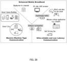
- the 5th generation mobile communication systems has features of enhanced mobile broadband (eMBB), massive machine type communication (mMTC), and ultra reliable and low latency communication (URLLC), and can flexibly provide radio communication in response to a wide variety of needs, by using these features.
- the 3rd Generation Partnership Project (3GPP) as an international standardizing body has been specifying New Radio (NR) as one of 5G radio interfaces.
- NR New Radio
- One non-limiting and exemplary embodiment of the present disclosure facilitates providing a communication apparatus and a communication method each capable of configuring a reference signal flexibly.
- a communication apparatus includes: control circuitry, which, in operation, makes a configuration of a reference signal to be assigned to a first section for a repetition transmission and a configuration of a reference signal to be assigned to a second section for the repetition transmission different from each other; and transmission circuitry, which, in operation, performs the repetition transmission based on the configurations of the reference signals.
- FR1 Frequency Range 1
- NPL Non-Patent Literature
- FR1 a high frequency band is possibly used compared with the frequency band used in Long Term Evolution (LTE) or 3rd Generation mobile communication systems (3G) such as 3.5 GHz band.
- LTE Long Term Evolution
- 3G 3rd Generation mobile communication systems
- a terminal transmits and receives data in accordance with resource allocation indicated by at least one of a layer-1 control signal (e.g., Downlink Control Information (DCI)) on a downlink control channel (e.g., Physical Downlink Control Channel (PDCCH)) from a base station (also referred to as, e.g., gNB) and Radio Resource Control (RRC) corresponding to layer 3 (e.g., see NPLs 3 to 6).
- a layer-1 control signal e.g., Downlink Control Information (DCI)
- DCI Downlink Control Information
- PDCCH Physical Downlink Control Channel
- RRC Radio Resource Control
- the terminal transmits an uplink data channel (e.g., Physical Uplink Shared Channel (PUSCH)) in accordance with the resource allocation (e.g., Grant or UL grant) from the base station.
- Information on the resource allocation included in at least one of the DCI and the RRC may include, for example, information on a time-domain resource with which PUSCH is transmitted.
- the information on the time-domain resource may include information (e.g., K2) on the timing (e.g., slot offset) from the slot in which the terminal has received PDCCH to the slot in which the terminal transmits PUSCH, the start-symbol position of PUSCH in the slot, or information on the number of symbols for transmitting PUSCH.
- the terminal can transmit PUSCH using a plurality of slots (this transmission is also referred to as Repetition).
- this transmission is also referred to as Repetition.
- the information on the time-domain resource for transmitting PUSCH may include information on the number of Repetitions.
- PUSCH repetition schemes are specified, for example (e.g., see NPL 6).
- the first Repetition scheme is a slot-by-slot Repetition in which the same time resource allocation is applied over multiple slots.
- this Repetition scheme is referred to as "PUSCH repetition Type A.”
- the second Repetition scheme is a scheme in which one or a plurality of PUSCHs is repeatedly transmitted in one slot.
- this Repetition scheme is referred to as "PUSCH repetition Type B.”
- PUSCH repetition Type B for example, a time-domain resource for a first (e.g., initial) PUSCH transmission (e.g., also referred to as Repetition or PUSCH occasion) and the number of repetitions may be indicated to a terminal.
- symbols may be assigned, which are consecutive to and in number identical to the previous PUSCH transmission.
- slot /Repetition may represent any of the slots and Repetitions (or PUSCH occasions) that are sections (time intervals) for repetition transmission of PUSCH in each Repetition scheme.
- NR Rel. 17 includes a method of counting the number of slots for repetition (hereinafter referred to as repetition slots) based on an uplink slot available for the PUSCH transmission, for example (e.g., see NPL 2).
- a reference signal used in channel estimation for demodulation e.g., Demodulation Reference Signal (DMRS)
- DMRS Demodulation Reference Signal
- a DMRS may be placed (e.g., front loaded) at the front of a slot, for example.
- DMRSs e.g., including additional DMRS
- NPLs 3 and 6 may be arranged in a plurality of symbols in a slot.
- the DMRS configuration may include, for example, parameters such as the number of DMRS symbols, the DMRS position, and the DMRS type in each slot/Repetition.
- a communication environment such that coverage enhancement can be performed, e.g., a communication environment with a lower Signal-to-Noise power Ratio (SNR) or Signal-to-Interference plus Noise power Ratio (SINR)
- SNR Signal-to-Noise power Ratio
- SINR Signal-to-Interference plus Noise power Ratio
- NR e.g., NR Rel. 15/16
- a channel estimation result demodulated (or estimated) by DMRS is available in the slot including the DMRS (i.e., not available in a slot different from slot including the DMRS).
- a method of combining DMRSs in multiple slots/Repetitions has been studied, for example (e.g., see NPL 6).
- the method of combining the DMRSs in the multiple slots/Repetitions is also referred to as, for example, inter-slot channel estimation, joint channel estimation, or DMRS bundling.
- the introduction of the method of combining the DMRSs in the multiple slots/Repetitions makes it possible to, for example, eliminate the aforementioned limitation on use of the channel estimation result demodulated by DMRS, thereby improving the received SNR of DMRS used in the channel estimation.
- the same DMRS configuration in each of the plurality of slots/Repetitions is not appropriate for the channel estimation in some cases.
- FIG. 1 illustrates an exemplary DMRS configuration where the number of repetition transmissions is twice and the time-resource allocation in each slot/Repetition is 14 symbols, as an example.
- the DMRS configuration illustrated in FIG. 1 may be, for example, a DMRS configuration based on the specification in NR Rel. 15/16.
- spacing between DMRSs arranged over two slots/Repetitions can be unequal.
- followability to the channel fluctuation can be improved by an arrangement of DMRSs at equal spacing in the sections of the multiple slots/Repetitions to which the joint channel estimation is applied rather than by the arrangement with unequal spacing, thus improving the transmission performance of the PUSCH repetition.
- FIG. 1 e.g., example of NR Rel. 15/16
- the number of DMRS symbols specific to a slot/Repetition cannot be changed due to the limitation on the DMRS configuration; as a result, overhead of DMRS may increase, and the transmission efficiency may be thus reduced.
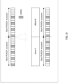
- FIG. 3 when the number of DMRS symbols is reduced for some of the multiple slots/Repetitions to which the joint channel estimation is applied (second slot /Repetition in FIG. 3 ), a resource to which data is mappable in this slot/Repetition increases, so that the transmission performance or transmission efficiency of the PUSCH repetition can be improved with a coding gain.
- the method of appropriately configuring the DMRS arrangement or the number of DMRS symbols may vary depending on, for example, a setting such as the number of slots/Repetitions to which the joint channel estimation is applied or the time-resource allocation for each slot/Repetition. Therefore, for each slot/Repetition to which the joint channel estimation is applied, it is expected to search for (e.g., optimize) a DMRS arrangement or the number of DMRS symbols having better transmission performance (e.g., Block Error Ratio (BLER) performance or transmission efficiency).
- BLER Block Error Ratio
- the number of combinations of the numbers of slots/Repetitions to which the joint channel estimation is applied and the time-resource allocation for each slot/Repetition is enormous, and thus, determining an appropriate (e.g., optimal) DMRS arrangement or number of DMRS symbols for each combination by search has a large impact on specification.
- pos 0, pos 1, pos 2, and pos 3 four types of combinations (e.g., pos 0, pos 1, pos 2, and pos 3) of the DMRS arrangements and the numbers of DMRS symbols are specified for 2 to 14 symbols of the time-resource allocation for each slot/Repetition (see, e.g., NPL 3).
- pos 0, pos 1, pos 2, and pos 3 four types of combinations (e.g., pos 0, pos 1, pos 2, and pos 3) of the DMRS arrangements and the numbers of DMRS symbols are specified for 2 to 14 symbols of the time-resource allocation for each slot/Repetition (see, e.g., NPL 3).
- Adding a new combination of the DMRS arrangement and the number of DMRS symbols in order to apply the joint channel estimation possibly complicates the hardware and software processing of DMRS generation in a transmitter.
- the hardware and software processing of channel estimation is possibly complicated on a reception side due to implementation of channel estimation for a new combination of the DMRS arrangement and the number of DMRS symbols in order to apply the joint channel estimation.
- a description will be given of a method of improving the flexibility of a DMRS configuration (e.g., configurations of DMRS arrangement and the number of DMRS symbols) and suppressing an increase in signaling overhead or the complexity of hardware/software processing in a transmitter and a receiver.
- a DMRS configuration e.g., configurations of DMRS arrangement and the number of DMRS symbols
- the already specified DMRS configurations e.g., by NR Rel. 15/16
- the DMRS configurations e.g., DMRS arrangements or the numbers of DMRS symbols
- DMRS arrangement and the number of DMRS symbols suitable for the channel estimation may vary depending on a channel state (e.g., SNR, SINR, or channel fluctuation). Therefore, even when the predetermined DMRS configuration is applied to each slot/Repetition, it is difficult to improve the channel estimation accuracy. Accordingly, it is expected that the DMRS configuration for each slot/Repetition will be configured dynamically in accordance with the channel state.
- an indication may be made to share a dynamic DMRS configuration between transmission and reception sides.
- the DCI overhead herein may increase, for example, when the number of slots/Repetitions to which the joint channel estimation is applied is N, up to 4 N patterns of indications are made in order to configure, for each of the slots/Repetitions, patterns of the four types of combinations (e.g., pos 0, pos 1, pos 2, and pos 3) of the DMRS arrangements and the numbers of DMRS symbols.
- information (or parameter) for determining a combination of DMRS configurations may be configured in advance for a terminal by a higher layer signalling (e.g., Radio Resource Control (RRC)).
- RRC Radio Resource Control
- the information for determining the DMRS configuration pattern may include, for example, information on a plurality of candidates for the DMRS configuration pattern for each of the plurality of slots/Repetitions.
- the terminal may determine a DMRS configuration pattern for each of slots/Repetitions actually used for transmission and reception, based on resource-allocation information included in the DCI or the RRC and the information for determining the DMRS configuration pattern for each slot/Repetition described above.
- the resource-allocation information may include information indicating any one of the plurality of candidates for the DMRS configuration pattern for each of the plurality of slots/Repetitions.
- DMRS configuration e.g., DMRS arrangement or the number of DMRS symbols
- a communication system includes base station 100 and terminal 200.
- FIG. 4 is a block diagram illustrating an exemplary configuration of part of base station 100 (e.g., corresponding to communication apparatus) according to an embodiment of the present disclosure.
- controller 101 e.g., corresponding to control circuitry
- Receiver 108 e.g., corresponding to reception circuitry performs the reception of the repetition transmission based on the configurations of the reference signals.
- FIG. 5 is a block diagram illustrating an exemplary configuration of part of terminal 200 (e.g., corresponding to communication apparatus) according to an embodiment of the present disclosure.
- controller 205 e.g., corresponding to control circuitry
- Transmitter 209 e.g., corresponding to transmission circuitry performs the repetition transmission based on the configurations of the reference signals.
- FIG. 6 is a block diagram illustrating an exemplary configuration of base station 100 according to Embodiment 1.
- base station 100 includes controller 101, higher-layer control signal generator 102, downlink control information generator 103, encoder 104, modulator 105, signal assigner 106, transmitter 107, receiver 108, extractor 109, demodulator 110, and decoder 111.
- Controller 101 determines (or identifies), based on, for example, the methods described below, information on a DMRS configuration (e.g., DMRS configuration pattern) for each of a plurality of slots/Repetitions. Controller 101 outputs the determined information on the DMRS configuration pattern to extractor 109, demodulator 110, and decoder 111, for example. Controller 101 may output the determined information on the DMRS configuration pattern to at least one of higher-layer control signal generator 102 and downlink control information generator 103.
- a DMRS configuration e.g., DMRS configuration pattern
- Controller 101 also determines, for example, information on reception of a downlink data signal (e.g., PDSCH) for terminal 200, information on transmission of an uplink data signal (e.g., PUSCH), and information on transmission of an uplink control signal (e.g., PUCCH), and outputs the determined information to higher-layer control signal generator 102.
- the information on the reception of the downlink data signal and the information on the transmission of the uplink data signal may include, for example, information on time-domain resource allocation (e.g., Time Domain Resource Allocation (TDRA)) (e.g., information on TDRA table) or information on Repetition (e.g., information on the number of Repetitions).
- TDRA Time Domain Resource Allocation
- the information on the transmission of the uplink control signal may include, for example, information on a PUCCH resource set. Further, for example, at least one of the information on the reception of the downlink data signal, the information on the transmission of the uplink data signal, and the information on the transmission of the uplink control signal may include the information on the DMRS configuration pattern described above.
- controller 101 determines, for example, information (e.g., coding and modulation scheme (MCS) and radio resource allocation) on a downlink signal for transmitting a downlink data signal, a higher-layer control signal or downlink control information, and outputs the determined information to encoder 104, modulator 105, and signal assigner 106. Controller 101 also outputs, for example, the information on the downlink signal (e.g., downlink data signal and higher-layer control signal) to downlink control information generator 103. Besides, for example, the information on the downlink signal may include the information on the DMRS configuration pattern described above.
- MCS coding and modulation scheme
- controller 101 determines information (e.g., MCS and radio resource allocation) on transmission of an uplink data signal (e.g., PUSCH) in terminal 200, for example. Controller 101 outputs the determined information on the uplink data signal to downlink control information generator 103, extractor 109, and decoder 111, for example. Besides, for example, the information on the uplink data signal may include the information on the DMRS configuration pattern described above.
- controller 101 determines information (e.g., PUCCH resource) on transmission of an uplink control signal (e.g., PUCCH) in terminal 200, for example.
- Controller 101 for example, outputs the determined information on the uplink control signal to higher-layer control signal generator 102 and downlink control information generator 103.
- Controller 101 also outputs the determined information on the uplink control signal to extractor 109, demodulator 110, and decoder 111.
- the information on the uplink control signal may include the information on the DMRS configuration pattern described above.
- Higher-layer control signal generator 102 for example, generates a higher-layer control signal bit sequence based on the information inputted from controller 101 and outputs the higher-layer control signal bit sequence to encoder 104.
- Downlink control information generator 103 for example, generates a downlink control information (e.g., DCI) bit sequence based on the information inputted from controller 101 and outputs the generated DCI bit sequence to encoder 104. Note that the control information may be transmitted to a plurality of terminals.
- DCI downlink control information
- Encoder 104 for example, encodes downlink data (e.g., DL data signal), the bit sequence inputted from higher-layer control signal generator 102, or the DCI bit sequence inputted from downlink control information generator 103, based on the information inputted from controller 101. Encoder 104 outputs the encoded bit sequence to modulator 105.
- downlink data e.g., DL data signal
- the bit sequence inputted from higher-layer control signal generator 102 the bit sequence inputted from higher-layer control signal generator 102
- DCI bit sequence inputted from downlink control information generator 103 based on the information inputted from controller 101.
- Encoder 104 outputs the encoded bit sequence to modulator 105.
- Modulator 105 for example, modulates the encoded bit sequence inputted from encoder 104, based on the information inputted from controller 101, and outputs the modulated signal (e.g., symbol sequence) to signal assigner 106.
- modulated signal e.g., symbol sequence
- Signal assigner 106 maps, to a radio resource, the symbol sequence (including, e.g., downlink data signal or control signal) inputted from modulator 105, based on the information indicating the radio resource inputted from controller 101, for example.
- Signal assigner 106 outputs, to transmitter 107, a downlink signal to which the signal is mapped.
- Transmitter 107 performs transmission-waveform generation processing such as orthogonal Frequency Division Multiplexing (OFDM) on the signal inputted from signal assigner 106.
- transmission-waveform generation processing such as orthogonal Frequency Division Multiplexing (OFDM)
- OFDM orthogonal Frequency Division Multiplexing
- transmitter 107 performs Inverse Fast Fourier Transform (IFFT) processing on the signal, and adds the CP to the signal resulting from the IFFT.
- IFFT Inverse Fast Fourier Transform
- transmitter 107 performs RF processing such as D/A conversion and/or up-conversion on the signal and transmits the resulting radio signal to terminal 200 via an antenna.
- Receiver 108 for example, performs RF processing such as down-conversion and/or A/D conversion on an uplink signal from terminal 200 received via an antenna. Further, in the case of the OFDM transmission, receiver 108 performs Fast Fourier Transform (FFT) processing on the received signal and outputs the resulting frequency-domain signal to extractor 109.
- FFT Fast Fourier Transform
- Extractor 109 extracts from the received signal inputted from receiver 108, based on the information inputted from controller 101, a radio resource part with which at least one of the uplink data signal (e.g., PUSCH) and the uplink control signal (e.g., PUCCH) has been transmitted and then outputs the extracted radio resource part to demodulator 110.
- PUSCH uplink data signal
- PUCCH uplink control signal
- Demodulator 110 demodulates the uplink data signal (e.g., PUSCH) or the uplink control signal (e.g., PUCCH) inputted from extractor 109, based on the information inputted from controller 101.
- Demodulator 110 for example, outputs a demodulation result to decoder 111.
- Decoder 111 for example, performs error correction decoding on the uplink data signal (e.g., PUSCH) or the uplink control signal (e.g., PUCCH), based on the information inputted from controller 101 and the demodulation result inputted from demodulator 110, thereby obtaining a reception bit sequence (e.g., UCI or UL data signal) after the decoding.
- the uplink data signal e.g., PUSCH
- the uplink control signal e.g., PUCCH
- FIG. 7 is a block diagram illustrating an exemplary configuration of terminal 200 according to an exemplary embodiment of the present disclosure.
- terminal 200 includes receiver 201, extractor 202, demodulator 203, decoder 204, controller 205, encoder 206, modulator 207, signal assigner 208, and transmitter 209.
- Receiver 201 receives a downlink signal (e.g., downlink data signal or downlink control information) from base station 100 via an antenna and performs the RF processing such as the down-conversion and/or the A/D conversion on the received radio signal, thereby obtains a received signal (baseband signal). Further, in the case of receiving an OFDM signal, receiver 201 performs the FFT processing on the received signal to convert the received signal into that in the frequency domain. Receiver 201 outputs the received signal to extractor 202.
- a downlink signal e.g., downlink data signal or downlink control information
- the RF processing such as the down-conversion and/or the A/D conversion on the received radio signal
- baseband signal baseband signal
- receiver 201 performs the FFT processing on the received signal to convert the received signal into that in the frequency domain.
- Receiver 201 outputs the received signal to extractor 202.
- Extractor 202 extracts a radio resource part that may include the downlink control information from the received signal inputted from receiver 201, based on information on the radio resource for the downlink control information inputted from controller 205, and then outputs the radio resource part to demodulator 203. Further, extractor 202 extracts a radio resource part that includes downlink data, based on information on the radio resource for a data signal inputted from controller 205, and then outputs the radio resource part to demodulator 203.
- Demodulator 203 for example, based on the information inputted from controller 205, demodulates the signal (e.g., PDCCH or PDSCH) inputted from extractor 202 and outputs a demodulation result to decoder 204.
- the signal e.g., PDCCH or PDSCH
- Decoder 204 for example, based on the information inputted from controller 205, performs error correction decoding on PDCCH or PDSCH, using the demodulation result inputted from demodulator 203, thereby obtaining downlink reception data, a higher-layer control signal, or downlink control information, for example. Decoder 204 outputs the higher-layer control signal and the downlink control information to controller 205, and outputs the downlink reception data. Further, decoder 204 may generate a response signal (e.g., ACK/NACK) based on the decoding result of the downlink reception data and output the generated response signal to encoder 206.
- a response signal e.g., ACK/NACK
- Controller 205 determines a radio resource for at least one of a PDSCH reception, a PUSCH transmission, and a PUCCH transmission, based on the signal inputted from decoder 204 (e.g., higher-layer control signal and downlink control information). Controller 205 also determines (or identifies) DMRS configurations for a plurality of slots/Repetitions based on the signal inputted from decoder 204 (e.g., information on DMRS configuration pattern). Controller 205 outputs the determined information to extractor 202, demodulator 203, encoder 206, modulator 207, and signal assigner 208, for example.
- decoder 204 e.g., higher-layer control signal and downlink control information
- Controller 205 also determines (or identifies) DMRS configurations for a plurality of slots/Repetitions based on the signal inputted from decoder 204 (e.g., information on DMRS configuration pattern). Controller 205 outputs the determined information to extractor 202
- Encoder 206 for example, performs error correction encoding on a UCI (UCI sequence) or an uplink data signal, based on the information inputted from controller 205. Encoder 206 outputs the encoded bit sequence to modulator 207.
- UCI UCI sequence
- Encoder 206 outputs the encoded bit sequence to modulator 207.
- Modulator 207 for example, based on the information inputted from controller 205, modulates the encoded bit sequence inputted from encoder 206 and outputs the modulated signal (symbol sequence) to signal assigner 208.
- Signal assigner 208 for example, based on the information inputted from controller 205, maps the signal inputted from modulator 207 to a radio resource. Further, signal assigner 208 maps a DMRS to a radio resource, based on information on a DMRS configuration pattern (e.g., DMRS arrangement and the number of symbols) included in the information inputted from the controller. Signal assigner 208 outputs, to transmitter 209, the uplink signal to which the signal is mapped.
- a DMRS configuration pattern e.g., DMRS arrangement and the number of symbols
- Transmitter 209 performs transmission signal-waveform generation such as OFDM on the signal inputted from signal assigner 208.
- transmitter 209 performs the IFFT processing on the signal and adds the CP to the signal after the IFFT.
- a Discrete Fourier Transformer may be additionally provided at a rear stage of modulator 207 or a front stage of signal assigner 208 (neither is illustrated), for example.
- transmitter 209 performs the RF processing such as the D/A conversion and/or the up-conversion on a transmission signal and transmits the resulting radio signal to base station 100 via an antenna.
- FIG. 8 is a flowchart describing an exemplary operation relating to a DMRS configuration in terminal 200.
- terminal 200 receives a parameter (or information) for a DMRS configuration pattern, for example (S101).
- a parameter or information for a DMRS configuration pattern
- terminal 200 may receive, in addition to the parameter for the DMRS configuration pattern, information for determining a DMRS configuration for each slot/Repetition (e.g., parameter specified in NR Rel. 15/16), for example.
- Terminal 200 determines whether to perform a repetition transmission (e.g., Repetition or joint channel estimation) in transmission of an uplink signal (e.g., PUSCH or PUCCH) and reception of a downlink signal (e.g., PDSCH) (S102).
- a repetition transmission e.g., Repetition or joint channel estimation
- an uplink signal e.g., PUSCH or PUCCH
- a downlink signal e.g., PDSCH
- terminal 200 When performing the repetition transmission (S102: Yes), terminal 200, for example, configures DMRS based on the parameter for the DMRS configuration pattern for each slot/Repetition (e.g., dmrs-AdditionalPositionPattern to be described later) (S103).
- the parameter for the DMRS configuration pattern for each slot/Repetition e.g., dmrs-AdditionalPositionPattern to be described later
- terminal 200 configures DMRS based on, for example, an existing parameter (e.g., parameter specified in NR Rel. 15/16, for example, dmrs-AdditionalPosition included in DMRS-UplinkConfig) (S104).
- an existing parameter e.g., parameter specified in NR Rel. 15/16, for example, dmrs-AdditionalPosition included in DMRS-UplinkConfig
- Terminal 200 may, for example, perform at least one of the transmission of the uplink signal (e.g., PUSCH or PUCCH) and the reception of the downlink signal (e.g., PDSCH), based on the DMRS configuration (S105).
- the uplink signal e.g., PUSCH or PUCCH
- the reception of the downlink signal e.g., PDSCH
- terminal 200 may, for example, compare the number of Repetitions (or the number of times of repetition) and a threshold, without limitation to the determination whether to perform the Repetition.
- terminal 200 may perform processing of S 103 when the number of Repetitions is equal to or larger than the threshold, and may perform processing of S104 when the number of Repetitions is less than the threshold.
- base station 100 may configure a parameter (e.g., a plurality of candidates for DMRS configuration pattern) for determining the DMRS configuration pattern for each slot/Repetition, for an information element (IE) of a higher layer (e.g., RRC) that configures the information on a time-domain resource for transmitting PUSCH.
- a parameter e.g., a plurality of candidates for DMRS configuration pattern
- IE information element
- RRC higher layer
- base station 100 may configure information indicating any one of the plurality of candidates in the parameter for determining the DMRS configuration pattern for each slot/Repetition, for resource-allocation information included in the downlink control information (DCI) or the RRC.
- DCI downlink control information
- RRC Radio Resource Control
- terminal 200 may determine the DMRS configuration pattern for each slot/Repetition based on the resource-allocation information included in the downlink control information (DCI) or the RRC and the parameter for determining the DMRS configuration pattern.
- DCI downlink control information
- RRC Radio Resource Control
- the information element herein of the RRC that configures the information on the time-domain resource with which PUSCH is transmitted may be, for example, "PUSCH-TimeDomainResourceAllocation IE" (see, e.g., NPL 7).
- the PUSCH-TimeDomainResourceAllocation may include, for example, parameters for information on the timing of how many slots later terminal 200 transmits PUSCH from the slot in which the terminal has received PDCCH, the start symbol position of PUSCH in a slot, the number of symbols for transmitting PUSCH, and the number of Repetitions (e.g., parameters in PUSCH-Allocation-r16).
- base station 100 may configure information (e.g., TDRA table or puschAllocationList-r16) on candidates for a combination of these parameters.
- Terminal 200 may select one of the plurality of combination candidates of parameters for a PUCSH transmission to be actually used by terminal 200, based on the DCI or RRC (e.g., a few bits) that assign the corresponding uplink data channel (PUSCH), for example.
- DCI Downlink Control
- RRC Radio Resource Control
- the PUSCH-TimeDomainResourceAllocation IE (e.g., PUS CH-Allocation-r 16) may include a parameter (e.g., denoted as "dmrs-AdditionalPositionPattern") for determining the DMRS configuration pattern for each slot/Repetition. Therefore, for example, a plurality of candidates for a PUSCH assignment (e.g., PUS CH-Allocation-r 16) including the parameter "dmrs-AdditionalPositionPattern" may be configured for the PUSCH-TimeDomainResourceAllocation.
- a parameter e.g., denoted as "dmrs-AdditionalPositionPattern"
- terminal 200 determines the DMRS configuration pattern for each slot/Repetition, based on the indication of the time-domain resource allocation for PUSCH by the DCI or the RRC (e.g., information (index) indicating any of candidates in TDRA table), for example.
- the dmrs-AdditionalPositionPattern is included in the information element of the RRC specified in NR Rel. 15/16, which causes no increase in signaling overhead for the indication of the DMRS configuration pattern.
- the DMRS configuration pattern for each slot/Repetition suitable for the channel estimation depends on, for example, the time-domain resource allocation (e.g., the number of symbols or the number of Repetitions).
- base station 100 can configure the DMRS configuration pattern suitable for the combination of parameters for each time-domain resource allocation, for example. Therefore, according to the present embodiment, for example, the DMRS configuration for each slot/Repetition can be dynamically configured in accordance with a channel state, thus improving the channel estimation accuracy.
- the DMRS configuration that is common to each slot/Repetition is configured by the parameter "dmrs-AdditionalPosition" included in a "DMRS-UplinkConfig," which is an information element for configuring information on DMRS in uplink (hereinafter may also be referred to as an "uplink DMRS").
- terminal 200 may use a configuration of the dmrs-AdditionalPositionPattern in preference to a configuration of the dmrs-AdditionalPosition.
- a parameter e.g., dmrs-AdditionalPositionPattern
- terminal 200 may use a configuration of the dmrs-AdditionalPositionPattern in preference to a configuration of the dmrs-AdditionalPosition.
- terminal 200 may use the PUSCH-TimeDomainResourceAllocation IE in preference to the DMRS-UplinkConfig IE. In other words, terminal 200 may ignore the configuration of the dmrs-AdditionalPosition when the dmrs-AdditionalPositionPattern) is configured for the PUSCH-TimeDomainResourceAllocation IE.
- a plurality of patterns (candidates) for the DMRS configuration in each slot/Repetition is previously defined, and one of the patterns may be configured for the dmrs-AdditionalPositionPattern.
- FIG. 10 illustrates an example of PUSCH-Allocation-r16 in Option 1-1.
- the Dmrs-AdditionalPositionPattern illustrated in FIG. 10 may include, for example, any one of four candidates for the DMRS configuration pattern (pattern 1, pattern 2, pattern 3, and pattern 4) for each slot/Repetition.
- FIG. 11 illustrates examples of the previously defined DMRS configuration patterns (e.g., candidates) for each slot/Repetition.
- a dmrs-AdditionalPosition is an existing parameter for indicating one of combinations of four types of DMRS arrangements and the numbers of DMRS symbols (e.g., pos 0, pos 1, pos 2, and pos 3).
- the Dmrs-AdditionalPosition is included in a DMRS-UplinkConfig, which is an information element for configuring information on an uplink DMRS.
- a DMRS configuration (any of pos 0 to pos 3) specified by the dmrs-AdditionalPosition may be configured for the first and third slots/Repetitions (1st repetition and 3rd repetition).
- a previously specified DMRS configuration may be configured for the second slot/Repetition (2nd repetition).
- the DMRS configuration specified for the second slot/Repetition may be, for example, any one of pos 0 to pos 3.
- the DMRS configuration for the second slot/Repetition may be different from the DMRS configuration for the first and third slots/Repetitions.
- the DMRS configuration patterns (pattern 1 to pattern 4) illustrated in FIG. 11 allow base station 100 to, for example, configure, for terminal 200, a DMRS configuration specific to each of the plurality of slots/Repetitions to which the joint channel estimation is applied.
- the previously defined DMRS configuration pattern for each slot/Repetition is not limited to the examples illustrated in FIG. 11 .
- the number of candidates for the DMRS configuration patterns for slots/Repetitions included in the dmrs-AdditionalPositionPattern is not limited to four and may be other numbers.
- the DMRS configuration specified by the dmrs-AdditionalPosition included in the DMRS-UplinkConfig may not be included.
- the number of bits of the RRC used for indicating the dmrs-AdditionalPositionPattern depends on the number of patterns (number of candidates).
- the number of bits used for configuring the dmrs-AdditionalPositionPattern in one PUSCH-Allocation-r16 is log 2 (P) bits for the number of patterns P.
- P log 2 bits for the number of patterns P.
- the number of bits used for configuring one PUSCH-Allocation-r16 is two bits.
- the DMRS configuration pattern for each of the slots/Repetitions may be configured by the RRC.
- FIG. 12 illustrates an example of PUSCH-Allocation-r16 in Option 1-2.
- the dmrs-AdditionalPositionPattern illustrated in FIG. 12 may include, for example, a DMRS configuration (e.g., any of pos 0, pos 1, pos 2, and pos 3 of dmrs-AdditionalPosition) for each of the slots/Repetitions the number of which is "numberOfRepetitions-r16" corresponding to the number of Repetitions.
- a DMRS configuration e.g., any of pos 0, pos 1, pos 2, and pos 3 of dmrs-AdditionalPosition
- the indication of the dmrs-AdditionalPositionPattern allows base station 100 to flexibly configure, for terminal 200, the DMRS configuration (e.g., any of pos 0, pos 1, pos 2, and pos 3) for each slot/Repetition.
- the DMRS configuration e.g., any of pos 0, pos 1, pos 2, and pos 3 for each slot/Repetition.
- FIG. 13 illustrates an exemplary DMRS arrangement using the dmrs-AdditionalPositionPattern in the present embodiment.
- FIG. 13 illustrates an example in which the number of Repetitions is twice.
- FIG. 13 illustrates an exemplary DMRS arrangement of a case where pattern 1 is configured for the dmrs-AdditionalPositionPattern whereas the dmrs-AdditionalPosition is pos 2 in FIG. 11 of Option 1-1, for example.
- FIG. 13 illustrates an exemplary DMRS arrangement of a case where ⁇ pos 2, pos 1 ⁇ are configured for the dmrs-AdditionalPositionPattern in Option 1-2, for example.
- different DMRS configurations for the respective slots/Repetitions i.e., individual DMRS arrangement
- a resource to which data is mappable can be increased in the second slot/Repetition, thereby improving the transmission performance or transmission efficiency of the PUSCH repetition.
- base station 100 and terminal 200 make a configuration of a DMRS to be assigned to a certain slot/Repetition section in repetition and a configuration of a DMRS to be assigned to another slot/Repetition in the repetition different from each other, for example.
- terminal 200 determines the DMRS configuration specific to each slot/Repetition, based on, for example, an information element of the RRC including a plurality of candidates for the DMRS configuration pattern specific to each slot/Repetition and a control signal included in the DCI or the RRC, which indicates any one of the plurality of candidates for the DMRS configuration pattern.
- the RRC which configures the information on the plurality of candidates for the DMRS configuration pattern for each of the plurality of slots/Repetitions, includes an information element relating to a configuration of a time-domain resource to which PUSCH is assigned (e.g., PUSCH-TimeDomainResourceAllocation IE), for example.
- an information element relating to a configuration of a time-domain resource to which PUSCH is assigned e.g., PUSCH-TimeDomainResourceAllocation IE
- base station 100 can appropriately configure a DMRS configuration pattern in according with the configurations of PUSCH such as the number of slots/Repetitions to which the joint channel estimation is applied or the time-resource allocation for each slot/Repetition.
- the existing indication of the time-resource allocation for PUSCH e.g., configuration specified in NR Rel. 15/16
- the impact of indications of the DMRS configuration patterns for the plurality of slots/Repetitions is small on the specifications.
- the signaling overhead can be suppressed and DMRS can be thus flexibly configured.
- the DMRS configurations applied to the respective slots/Repetitions to which the joint channel estimation is applied may be, for example, combinations of DMRS arrangements and the numbers of DMRS symbols specified in NR Rel. 15/16 (e.g., pos 0, pos 1, pos 2, and pos 3). This eliminates the need for adding a new combination of the DMRS arrangement and the number of DMRS symbols in order to apply the joint channel estimation, thus suppressing the complexity of the hardware and software processing of the DMRS generation in the transmitter and the hardware and software processing of the joint channel estimation in the receiver.
- a DMRS configuration pattern for each slot/Repetition may be specific to a Repetition method (e.g., type of repetition transmission).
- the repetition methods may include, for example, PUSCH repetition Type A and PUSCH repetition Type B.
- individual DMRS configuration patterns may be configured for PUSCH repetition Type A and PUSCH repetition Type B, respectively.
- FIG. 14 illustrates an example in which a DMRS configuration pattern is individually configured for PUSCH repetition Type A and PUSCH repetition Type B in Option 1-1.
- FIG. 15 illustrates an example in which a DMRS configuration pattern is individually configured for PUSCH repetition Type A and PUSCH repetition Type B in Option 1-2.
- the PUSCH-Allocation-r16 may include, for example, a parameter for determining the DMRS configuration pattern for each slot/Repetition for PUSCH repetition Type A (e.g., dmrs-AdditionalPositionPatternTypeA) and a parameter for determining the DMRS configuration pattern for each slot/Repetition for PUSCH repetition Type B (e.g., dmrs-AdditionalPositionPatternTypeB).
- a parameter for determining the DMRS configuration pattern for each slot/Repetition for PUSCH repetition Type A e.g., dmrs-AdditionalPositionPatternTypeA
- a parameter for determining the DMRS configuration pattern for each slot/Repetition for PUSCH repetition Type B e.g., dmrs-AdditionalPositionPatternTypeB
- base station 100 can appropriately determine a DMRS configuration depending on a Repetition method, for example.
- a value of the dmrs-AdditionalPosition (e.g., any of pos 0, pos 1, pos 2, and pos 3) included in the DMRS-UplinkConfig is configured for the parameter for determining the DMRS configuration pattern for each slot/Repetition (e.g., dmrs-AdditionalPositionPattern).
- a parameter e.g., dmrs-AdditionalPositionPattern
- a parameter e.g., dmrs-AdditionalPositionPattern
- dmrs-AdditionalPositionPattern that can be individually configured for each slot/Repetition is not limited to this case.
- a parameter (e.g., dmrs-AdditionalPositionPattern) that can be individually configured for each slot/Repetition may be a value corresponding to at least one of parameters relating to the DMRS arrangement (or DMRS position) and the number of DMRS symbols and other parameters for DMRS.
- the parameters for DMRS may include a DMRS type and a DMRS length.
- FIG. 16 illustrates an example of PUSCH-Allocation-r16 according to Variation 2.
- the dmrs-AdditionalPositionPattern illustrated in FIG. 16 may include, for example, a DMRS configuration (e.g., value of DMRS-UplinkConfig) for each of the slots/Repetitions the number of which is "numberOfRepetitions-r16" corresponding to the number of Repetitions.
- DMRS configuration e.g., value of DMRS-UplinkConfig
- the DMRS-UplinkConfig is an information element for configuring information on an uplink DMRS and may include, for example, parameters such as a DMRS arrangement and the number of DMRS symbols (dmrs-AdditionalPosition), a DMRS type (dmrs-Type), and a DMRS length (maxLength) in each of the slots/Repetitions.
- parameters such as a DMRS arrangement and the number of DMRS symbols (dmrs-AdditionalPosition), a DMRS type (dmrs-Type), and a DMRS length (maxLength) in each of the slots/Repetitions.
- a detailed configuration can be made for DMRS in each slot/Repetition. Therefore, for example, the channel estimation accuracy can be improved by the DMRS configuration in accordance with the channel state in each slot/Repetition.
- the size of parameter e.g., dmrs-AdditionalPositionPattern
- the size of DMRS configuration pattern may be different from the number of Repetitions.
- the size of dmrs-AdditionalPositionPattern may be a size that is previously defined or a size to be configured by the RRC. According to Variation 3, for example, when the size of dmrs-AdditionalPositionPattern is smaller than the number of Repetitions, an increase in the RRC overhead can be suppressed.
- the dmrs-AdditionalPositionPattern in Option 1-2 may be configured as in (a) of FIG. 17 .
- the DMRS configuration for an initial PUSCH transmission (1st repetition) may be determined based on a first element of the dmrs-AdditionalPositionPattern, whereas the DMRS configurations for the other PUSCH transmissions may be determined based on a second element of the dmrs-AdditionalPositionPattern. For example, it is effective in speeding up the decoding processing to configure the number of DMRS symbols for the initial PUSCH transmission to be larger than the numbers of DMRS symbols for the other PUSCH transmissions.
- the dmrs-AdditionalPositionPattern in Option 1-2 may be configured as in (b) of FIG. 17 .
- the DMRS configuration for the initial PUSCH transmission (1st repetition) may be determined based on the first element of the dmrs-AdditionalPositionPattern
- the DMRS configuration for the last PUSCH transmission (last repetition) may be determined based on the second element of the dmrs-AdditionalPositionPattern
- the DMRS configurations for PUSCH transmissions different from the initial and last PUSCH transmissions may be determined based on a third element. Improving the flexibility of the DMRS configurations in the leading and trailing PUSCH transmissions is useful in interpolation in time domain of channel estimation values in the inter-slot channel estimation, for example.
- the DMRS configuration for the m-th PUSCH transmission may be determined based on the (m mod N)-th element.
- the size, N, of dmrs-AdditionalPositionPattern is less than the number of Repetitions, DMRS configurations corresponding to the respective elements of the dmrs-AdditionalPositionPattern may be repeatedly applied.
- An association of the order of PUSCH transmissions and the elements of the dmrs-AdditionalPositionPatterns is not limited to the above-mentioned examples.
- the configurations of the base station and the terminal according to the present embodiment may be the same as the configurations of base station 100 and terminal 200 according to Embodiment 1.
- base station 100 may, for example, configure a parameter for determining the DMRS configuration pattern for each slot/Repetition, for an information element for configuring information on DMRS in uplink (e.g., information element relating to configuration of uplink DMRS).
- a parameter for determining the DMRS configuration pattern for each slot/Repetition for an information element for configuring information on DMRS in uplink (e.g., information element relating to configuration of uplink DMRS).
- terminal 200 may determine the DMRS configuration pattern for each slot/Repetition, at least based on an information element for which the parameter is configured.
- the information element herein for configuring the information on the uplink DMRS may be, for example, "DMRS-UplinkConfig IE" (see, e.g., NPL 7).
- the DMRS-UplinkConfig IE may include a parameter (e.g., denoted as "dmrs-AdditionalPositionPattern") for determining the DMRS configuration pattern for each slot/Repetition. Therefore, for example, a parameter set relating to the DMRS configurations including the parameter "dmrs-AdditionalPositionPattern" may be configured for the DMRS-UplinkConfig.
- a parameter set relating to the DMRS configurations including the parameter "dmrs-AdditionalPositionPattern" may be configured for the DMRS-UplinkConfig.
- the dmrs-AdditionalPositionPattern is included in the information element for configuring the information on the uplink DMRS, and the parameters for the DMRS configuration are thereby aggregated into a single information element, thus simplifying a configuration of the RRC.
- the "dmrs-AdditionalPosition" is a parameter for indicating any one of the four types of combinations (pos 0, pos 1, pos 2, and pos 3) of DMRS arrangements and the numbers of DMRS symbols.
- pos 2 is configured.
- the "dmrs-AdditionalPositionPattern" can individually configure any of values of the dmrs-AdditionalPosition (e.g., any of pos 0, pos 1, pos 2, and pos 3), for each of the slots/Repetitions the number of which is "maxNrofRepetition" corresponding to the number of Repetitions.
- base station 100 and terminal 200 make a configuration of a DMRS to be assigned to a certain slot/Repetition section in repetition and a configuration of a DMRS to be assigned to another slot/Repetition in the repetition different from each other.
- the RRC which configures the information on the plurality of candidates for the DMRS configuration pattern for each of the plurality of slots/Repetitions, includes an information element relating to s configuration of an uplink DMRS (e.g., DMRS-UplinkConfig IE).
- the existing indication of the DMRS configuration in uplink (e.g., configuration specified in NR Rel. 15/16) can be used for the configurations of the time-resource allocation and the DMRS arrangement for each slot/Repetition to which the joint channel estimation is applied, and thus, the impact of indications of the DMRS configuration patterns for the plurality of slots/Repetitions is small on the specification.
- the signaling overhead can be suppressed and DMRS can be flexibly configured.
- the DMRS configurations applied to the respective slots/Repetitions to which the joint channel estimation is applied may be, for example, combinations of DMRS arrangements and the numbers of DMRS symbols specified in NR Rel. 15/16 (e.g., pos 0, pos 1, pos 2, and pos 3). This eliminates the need for adding a new combination of the DMRS arrangement and the number of DMRS symbols in order to apply the joint channel estimation, thus suppressing the complexity of the hardware and software processing of the DMRS generation in the transmitter and the hardware and software processing of the joint channel estimation in the receiver.
- the present embodiment is not limited to a method of adding the dmrs-AdditionalPositionPattern to the DMRS-UplinkConfig, and the dmrs-AdditionalPosition, which is the existing parameter, may be extend to multiple dimensions, for example.
- the DMRS configuration patterns for the respective slots/Repetitions may be determined based on N elements sequentially from the first element of the dmrs-AdditionalPosition.
- the DMRS configuration pattern may be determined based on the first element of the dmrs-AdditionalPosition.
- the elements of the dmrs-AdditionalPosition that are configured in the case of application of the Repetition in number N or no Repetition are not limited to the elements in order from the first element.
- the size of dmrs-AdditionalPositionPattern or dmrs-AdditionalPosition of a case where the dmrs-AdditionalPosition, which is the existing parameter, is extended to the multiple dimensions may be different from the number of Repetitions.
- the size of dmrs-AdditionalPositionPattern or dmrs-AdditionalPosition of a case where the dmrs-AdditionalPosition, which is the existing parameter, is extended to the multiple dimensions may be a size that is previously defined or a size to be configured by the RRC.
- Variation 4 for example, when the size of dmrs-AdditionalPositionPattern is smaller than the number of Repetitions, an increase in the RRC overhead can be suppressed.
- the DMRS configuration for an initial PUSCH transmission (1st repetition) may be determined based on a first element of the dmrs-AdditionalPositionPattern, whereas the DMRS configurations for the other PUSCH transmissions may be determined based on a second element of the dmrs-AdditionalPositionPattern.
- the DMRS configuration for the initial PUSCH transmission (1st repetition) may be determined based on the first element of the dmrs-AdditionalPositionPattern
- the DMRS configuration for the last PUSCH transmission (last repetition) may be determined based on the second element of the dmrs-AdditionalPositionPattern
- the DMRS configurations for PUSCH transmissions different from the initial and last PUSCH transmissions may be determined based on a third element. Improving the flexibility of the DMRS configurations in the leading and trailing PUSCH transmissions is useful in interpolation in time domain of channel estimation values in the inter-slot channel estimation, for example.
- the DMRS configuration for the m-th PUSCH transmission may be determined based on the (m mod N)-th element.
- the size, N, of dmrs-AdditionalPositionPattern is less than the number of Repetitions, DMRS configurations corresponding to the respective elements of the dmrs-AdditionalPositionPattern may be repeatedly applied.
- An association of the order of PUSCH transmissions and the elements of the dmrs-AdditionalPositionPatterns is not limited to the above-mentioned examples.
- the dmrs-AdditionalPositionPattern or the dmrs-AdditionalPosition may be a parameter for configuring the DMRS configuration pattern (combination) for each slot/Repetition.
- an information element for configuring information on an uplink DMRS may include a parameter for configuring a plurality of candidates for the DMRS configuration pattern.
- FIG. 19 illustrates an exemplary DMRS-UplinkConfig IE according to Variation 5.
- the dmrs-AdditionalPositionPattern illustrated in FIG. 19 may include a pattern of a DMRS configuration (e.g., any of elements of dmrs-AdditionalPosition) for each of a plurality (e.g., in number corresponding to maxNrofRepetition) of slots/Repetitions.
- the dmrs-AdditionalPositionPatternList illustrated in FIG. 19 may include a plurality of candidates for a plurality (e.g., in number corresponding to maxNrofPatterns) of patterns (e.g., dmrs-AdditionalPositionPatterns).
- Terminal 200 may, for example, select one of the plurality of candidates for the DMRS configuration patterns for a PUCSH transmission to be actually used by terminal 200, based on the DCI or the RRC (e.g., a few bits) that has assigned the corresponding uplink data channel (PUSCH).
- the DCI or the RRC e.g., a few bits
- the DMRS configuration pattern in the DMRS-UplinkConfig may be configured (indicated), based on an index that indicates the time-domain resource allocation for the PUSCH transmission (e.g., PUSCH-TimeDomainResourceAllocation).
- an index that indicates the time-domain resource allocation for the PUSCH transmission e.g., PUSCH-TimeDomainResourceAllocation.
- the DMRS configuration pattern may be configured correspondingly to a value of another DCI-bit field, without limitation to the index indicating the time-domain resource allocation for the PUSCH transmission. This can suppress an increase in the DCI overhead and can dynamically configure the DMRS configuration pattern.
- some of combinations of the DMRS configuration patterns may be activated by a MAC Control Element (CE).
- CE MAC Control Element
- terminal 200 may select, based on the DCI, one of the DMRS configuration patterns from the activated combinations of the DMRS configuration patterns.
- DMRS configuration patterns that are not activated may not be configured (or selected) for terminal 200.
- terminal 200 can select an appropriate DMRS configuration pattern that is in accordance with a channel state on terminal 200, from the plurality of candidates for the DMRS configuration patterns that is configured by the DMRS-UplinkConfig.
- a parameter for determining the DMRS configuration pattern for each slot or Repetition in Embodiments 1 and 2 described above may be applied to the DMRS configurations for some of sections of the plurality of slots/Repetitions (e.g., corresponding to first and second sections), and need not be applied to the DMRS configurations of the remaining slots/Repetitions (e.g., corresponding to third section).
- the DMRS configuration for an initial PUSCH transmission (1st repetition) may be determined based on the dmrs-AdditionalPosition
- the DMRS configuration for PUSCH transmissions other than the initial transmission may be determined based on the dmrs-AdditionalPositionPattern (called Variation 6-1).
- the DMRS configurations for the initial PUSCH transmission (1st repetition) and the last PUSCH transmission (last repetition) may be determined based on the dmrs-AdditionalPosition
- the DMRS configurations for PUSCH transmissions other than the initial and last PUSCH transmissions may be determined based on the dmrs-AdditionalPositionPattern (called Variation 6-2).
- whether to determine the DMRS configurations for some or all of the slots/Repetitions based on the dmrs-AdditionalPositionPattern as in Variation 6-1 and Variation 6-2 may be switchable. Switching of the DMRS configuration that is based on the dmrs-AdditionalPositionPattern may be indicated to terminal 200 by the RRC, the MAC-CE, or the DCI, or may be implicitly configured.
- the configurations of the base station and the terminal according to the present embodiment may be the same as the configurations of base station 100 and terminal 200 according to Embodiment 1.
- a symbol offset may be included in a parameter for determining the DMRS configuration pattern for each slot/Repetition.
- the symbol offset may indicate, for example, an offset value for a DMRS symbol position specified in NR Rel. 15/16.
- the symbol offset may be included in the information element (e.g., PUSCH-TimeDomainResourceAllocation IE) for configuring the information on the time-domain resource with which PUSCH is transmitted, as in Embodiment 1, or may be included in the information element (e.g., DMRS-UplinkConfig) for configuring the information on the uplink DMRS, as in Embodiment 2.
- the information element e.g., PUSCH-TimeDomainResourceAllocation IE
- DMRS-UplinkConfig for configuring the information on the uplink DMRS
- parameter for configuring the symbol offset may be applied in the same manner as in Embodiments 1 and 2 by being replaced with the "dmrs-AdditionalPositionPattern," for example.
- the parameter for configuring the symbol offset may be applied in the same manner as in Embodiments 1 and 2 by being included, in conjunction with the "dmrs-AdditionalPositionPattern," in the information element for configuring the information on the time-domain resource for transmitting PUSCH or the information element for configuring the information on the uplink DMRS, for example.
- FIG.20 illustrates in (a), as an example, a configuration example of PUSCH-Allocation-r16 of a case where the dmrs-AdditionalPositionPattern is replaced with the parameter for configuring the symbol offset in Option 1-2 of Embodiment 1.
- the PUSCH-Allocation-r16 may include a parameter (e.g., "dmrs-offsetPattern") indicating a combination (symbol offset pattern) of symbol offsets (e.g., dmrs-offsets) respectively configured for the plurality (e.g., in number corresponding to numberOfRepetitions-r16) of slots/Repetitions.
- a parameter e.g., "dmrs-offsetPattern”
- dmrs-offsetPattern indicating a combination (symbol offset pattern) of symbol offsets (e.g., dmrs-offsets) respectively configured for the plurality (e.g., in number corresponding to numberOfRepetitions-r16) of slots/Repetitions.
- the dmrs-offset may be, for example, a parameter indicating how many symbols the DMRS symbol position in each slot/Repetition (e.g., DMRS symbol position configured by dmrs-AdditionalPosition) is shifted. For example, when the number of symbols in a slot or one Repetition is 14 symbols as illustrated in (b) of FIG. 20 , the dmrs-offset may be configured with any value from 0 to 13.
- FIG. 21 illustrates an exemplary DMRS arrangement using a symbol offset (dmrs-offset) in Embodiment 3.
- DMRS symbol positions in each slot/Repetition prior to the application of the symbol offset may be configured to be certain specified positions (e.g., DMRS symbol positions defined in NR Rel. 15/16).
- FIG. 21 illustrates an exemplary DMRS arrangement of a case where ⁇ 2, 0 ⁇ is indicated to terminal 200 by the dmrs-offset (offset), as an example.
- FIG. 21 a case has been described where the symbol offset that is individually configured for each slot/Repetition is applied to the DMRS symbol positions common to a plurality of slots/Repetitions, but the present disclosure is not limited to this case, and a symbol offset that is individually configured for each slot/Repetition may be applied to a DMRS symbol position specific to each of the plurality of slots/Repetitions, for example.
- the symbol offset indicates an offset in a positive direction for a certain DMRS symbol position; however, not limited thereto, and the symbol offset may indicate an offset in a negative direction.
- a symbol offset is added to a certain DMRS symbol position
- the present disclosure is not limited to this case, and a formula for calculating (i.e., converting) a new DMRS symbol position may be applied to a certain DMRS symbol position.
- an exemplary offset for the DMSR arrangement (or DMRS symbol position) has been described, but the present disclosure is not limited to this, and an offset for the number of DMRS symbols in the existing DMRS configuration (e.g., increase or decrease in the number of symbols) may be configured, for example.
- frequency hopping may be applied to the Repetition.
- the size of DMRS configuration pattern may be configured to be identical to a frequency hopping section (e.g., hop duration), and the above-described embodiments may be then applied.
- the DMRS configuration pattern may be initialized and applied per frequency hopping section.
- FIG. 22 illustrates an exemplary DMRS arrangement of a case where the frequency hopping is applied to the Repetition.
- the dmrs-AdditionalPositionPattern indicates ⁇ pos 2, pos 1, pos 1, pos 1 ⁇ to terminal 200.
- the DMRS configuration pattern is initialized per frequency hopping section (e.g., two-slot section or two-Repetition section), so that ⁇ pos 2, pos 1 ⁇ may be applied to each of the frequency hopping sections.
- precoding may be applied to the Repetition.
- the size of DMRS configuration pattern may be configured to be identical to a section to which the same precoding is applied, and the above-described embodiments may be then applied.
- the DMRS configuration pattern may be initialized and applied per precoding section.
- FIG. 23 illustrates an exemplary DMRS arrangement of a case where the precoding is applied to the Repetition.
- the dmrs-AdditionalPositionPattern indicates ⁇ pos 2, pos 1, pos 1, pos 1 ⁇ to terminal 200.
- the DMRS configuration pattern is initialized per section to which the same precoding is applied, so that ⁇ pos 2, pos 1 ⁇ may be applied to each of the precoding sections.
- a signal to be repeated may not only be transmitted in consecutive slots but also may be transmitted between non-consecutive slots.
- the inter-slot channel estimation may be applicable between the consecutive slots while the inter-slot channel estimation may not be applied between the non-consecutive slots.
- the size of DMRS configuration pattern may be configured to be identical to the number of consecutive slots, and the above-described embodiments may be then applied.
- the DMRS configuration pattern may be initialized and applied between non-consecutive slots.
- FIG. 24 illustrates an exemplary DMRS arrangement of a case where the Repetition including a non-consecutive slot is applied.
- the dmrs-AdditionalPositionPattern indicates ⁇ pos 2, pos 1, pos 1, pos 1 ⁇ to terminal 200.
- ⁇ pos 2, pos 1 ⁇ may be applied to the first and second Repetition sections and the third and fourth Repetition sections.
- the slot section to which the inter-slot channel estimation is applied is not limited to being defined as consecutive or non-consecutive slots, and even between consecutive slots, the number of slots to which the inter-slot channel estimation is applied may be varied (e.g., limited) depending on capability of terminal 200, for example. Therefore, the size of DMRS configuration pattern may be configured to be identical to the slot section to which the inter-slot channel estimation is applied, and the above-described embodiments may be then applied.
- the slot section to which the inter-slot channel estimation is applied may be configured, for terminal 200, as a slot section in which terminal 200 maintains the continuity of phase of a transmission signal or a slot section in which a transmission power of the transmission signal is constant (e.g., time domain window), for example.
- different precoding sections, between non-consecutive slots, or slot sections to which different types of inter-slot channel estimation are applied for example, the same DMRS configuration pattern may be applied, or different DMRS configuration patterns may be applied.
- a dmrs-AdditionalPositionPattern may be individually configured for the different frequency hopping sections, the different precoding sections, between the non-consecutive slots, or the slot sections to which the different types of inter-slot channel estimation are applied.
- the embodiments and variations may be applied to PUSCH repetition Type A.
- the DMRS configuration such as a DMRS arrangement or the number of DMRS symbols may be varied between slots/Repetitions.
- the embodiments and variations may also be applied to, for example, PUSCH repetition Type B.
- the DMRS configuration such as a DMRS arrangement or the number of DMRS symbols may be varied between Repetitions.
- the embodiments and variations may be applied to, for example, "TB processing over multi-slot PUSCH (TBoMS)" in which transport blocks are mapped to a plurality of PUSCH slots and then transmitted, the introduction of which has been discussed in Rel. 17 (e.g., see NPL 2).
- the DMRS configuration such as the DMRS arrangement or the number of DMRS symbols may be varied between slots or in units of PUSCH resources allocated by a start and length indicator value (SLIV).
- SIV start and length indicator value
- the DMRS configuration such as the DMRS arrangement or the number of DMRS symbols may be varied in units of Repetitions in the TBoMS.
- the embodiments and variations may be applied to, for example, a PUCCH repetition.
- the DMRS configuration such as a DMRS arrangement or the number of DMRS symbols may be varied between slots or between subslots.
- a parameter corresponding to the above-described "dmrs-AdditionalPositionPattern" may be included in a "PUCCH-FormatConfig" information element that includes a parameter for a PUCCH resource, or the pre-existing parameter "additionalDMRS" may be extended to multiple dimensions.
- a parameter corresponding to the above-described "dmrs-AdditionalPositionPattern" may be included in an information element that includes a parameter for resource configuration of Msg.3 PUSCH and may be included in, for example, PUSCH-Allocation-CovEnh or Msg3-DMRS-Config-CovEnh.
- the embodiments and variations may be applied to, for example, a PDSCH repetition.
- the DMRS configuration such as a DMRS arrangement or the number of DMRS symbols may be varied between slots/Repetitions.
- SPS Semi-Persistent Scheduling
- the communication apparatus for transmitting DMRS is not limited to terminal 200 and may be base station 100.
- the communication apparatus for receiving DMRS is not limited to base station 100 and may be terminal 200.
- the embodiments or variations may be applied to either one or both of an uplink communication and a downlink communication.
- the names of the information elements or the names of the parameters configured for the information elements used in the embodiments or variations are exemplary, and other names may be possible.
- the values of the parameters described in the embodiments or variations, such as the number of Repetitions, the number of DMRSs, the DMRS length, the DMRS symbol position, and the number of symbols in a slot, are exemplary, and other values may be possible.
- Information indicating whether terminal 200 supports the functions, operations, or processes that have been described in the above-mentioned embodiments and variations may be transmitted (or indicated) from terminal 200 to base station 100, as capability information or a capability parameter for terminal 200, for example.
- the capacity information may include information elements (IEs) that individually indicate whether terminal 200 supports at least one of the functions, operations, or processes that have been described in the above-mentioned embodiments and variations.
- the capability information may include information elements that indicate whether terminal 200 supports a combination of any two or more of the functions, operations, or processes that have been described in the above-mentioned embodiments and variations.
- Base station 100 may determine (or decide or assume), for example, based on the capability information received from terminal 200, the functions, operations, or processes that are supported (or not supported) by terminal 200, which is a transmission source of the capability information. Base station 100 may execute operations, processes, or control in accordance with a determination result based on the capability information. By way of example, base station 100 may control a repetition transmission in at least one of uplink or downlink, based on the capability information received from terminal 200.
- terminal 200 does not entirely support the functions, operations, or processes described in the above-mentioned embodiments and variations, such an unsupported part of the functions, operations, or processes may be interpreted as a limitation in terminal 200.
- information or a request relating to such limitation may be indicated to base station 100.
- the information on the capability or the limitation of terminal 200 may be defined by standards or may be implicitly indicated to base station 100 in association with information known in base station 100 or information to be transmitted to base station 100, for example.
- the downlink control signal (information) related to the present disclosure may be a signal (information) transmitted through PDCCH of the physical layer or may be a signal (information) transmitted through a MAC Control Element (CE) of the higher layer or the RRC.
- the downlink control signal may be a pre-defined signal (information).
- the uplink control signal (information) related to the present disclosure may be a signal (information) transmitted through PUCCH of the physical layer or may be a signal (information) transmitted through a MAC CE of the higher layer or the RRC. Further, the uplink control signal may be a pre-defined signal (information).
- the uplink control signal may be replaced with uplink control information (UCI), the 1st stage sidelink control information (SCI) or the 2nd stage SCI.
- the base station may be a Transmission Reception Point (TRP), a clusterhead, an access point, a Remote Radio Head (RRH), an eNodeB (eNB), a gNodeB (gNB), a Base Station (BS), a Base Transceiver Station (BTS), a base unit or a gateway, for example.
- TRP Transmission Reception Point
- RRH Remote Radio Head
- eNB eNodeB
- gNB gNodeB
- BS Base Station
- BTS Base Transceiver Station
- a terminal may serve as a base station.
- the base station may be a relay apparatus that relays communication between a higher node and a terminal.
- the base station may be a roadside unit as well.
- the present disclosure may be applied to any of uplink, downlink and sidelink.
- uplink channels such as PUSCH, PUCCH, and PRACH
- downlink channels such as PDSCH, PDCCH, and PBCH
- side link channels such as Physical Sidelink Shared Channel (PSSCH), Physical Sidelink Control Channel (PSCCH), and Physical Sidelink Broadcast Channel (PSBCH).
- PSSCH Physical Sidelink Shared Channel
- PSCCH Physical Sidelink Control Channel
- PSBCH Physical Sidelink Broadcast Channel
- PDCCH, PDSCH, PUSCH, and PUCCH are examples of a downlink control channel, a downlink data channel, an uplink data channel, and an uplink control channel, respectively.
- PSCCH and PSSCH are examples of a sidelink control channel and a sidelink data channel, respectively.
- PBCH and PSBCH are examples of broadcast channels, respectively, and PRACH is an example of a random access channel.
- the present disclosure may be applied to any of data channels and control channels.
- the channels in the present disclosure may be replaced with data channels including PDSCH, PUSCH and PSSCH and/or control channels including PDCCH, PUCCH, PBCH, PSCCH, and PSBCH.
- the reference signals are signals known to both a base station and a mobile station and each reference signal may be referred to as a Reference Signal (RS) or sometimes a pilot signal.
- the reference signal may be any of a DMRS, a Channel State Information - Reference Signal (CSI-RS), a Tracking Reference Signal (TRS), a Phase Tracking Reference Signal (PTRS), a Cell-specific Reference Signal (CRS), and a Sounding Reference Signal (SRS).
- CSI-RS Channel State Information - Reference Signal
- TRS Tracking Reference Signal
- PTRS Phase Tracking Reference Signal
- CRS Cell-specific Reference Signal
- SRS Sounding Reference Signal
- time resource units are not limited to one or a combination of slots and symbols, and may be time resource units, such as frames, superframes, subframes, slots, time slots, subslots, minislots, or time resource units, such as symbols, Orthogonal Frequency Division Multiplexing (OFDM) symbols, Single Carrier-Frequency Division Multiple Access (SC-FDMA) symbols, or other time resource units.
- time resource units such as frames, superframes, subframes, slots, time slots, subslots, minislots, or time resource units, such as symbols, Orthogonal Frequency Division Multiplexing (OFDM) symbols, Single Carrier-Frequency Division Multiple Access (SC-FDMA) symbols, or other time resource units.
- OFDM Orthogonal Frequency Division Multiplexing
- SC-FDMA Single Carrier-Frequency Division Multiple Access
- the present disclosure may be applied to any of a licensed band and an unlicensed band.
- the present disclosure may be applied to any of communication between a base station and a terminal (Uu-link communication), communication between a terminal and a terminal (Sidelink communication), and Vehicle to Everything (V2X) communication.
- the channels in the present disclosure may be replaced with PSCCH, PSSCH, Physical Sidelink Feedback Channel (PSFCH), PSBCH, PDCCH, PUCCH, PDSCH, PUSCH, and PBCH.
- the present disclosure may be applied to any of a terrestrial network or a network other than a terrestrial network (NTN: Non-Terrestrial Network) using a satellite or a High Altitude Pseudo Satellite (HAPS).
- NTN Non-Terrestrial Network
- HAPS High Altitude Pseudo Satellite
- the present disclosure may be applied to a network having a large cell size, and a terrestrial network with a large latency compared with a symbol length or a slot length, such as an ultra-wideband transmission network.
- An antenna port refers to a logical antenna (antenna group) formed of one or more physical antenna(s). That is, the antenna port does not necessarily refer to one physical antenna and sometimes refers to an array antenna formed of multiple antennas or the like. For example, it is not defined how many physical antennas form the antenna port, and instead, the antenna port is defined as the minimum unit through which a terminal is allowed to transmit a reference signal. The antenna port may also be defined as the minimum unit for multiplication of a precoding vector weighting.
- 5G 5th generation cellular technology
- NR new radio access technology
- the first version of the 5G standard was completed at the end of 2017, which allows proceeding to 5G NR standard-compliant trials and commercial deployments of terminals (e.g., smartphones).
- the overall system architecture assumes an NG-RAN (Next Generation-Radio Access Network) that includes gNBs, providing the NG-radio access user plane (SDAP/PDCP/RLC/MAC/PHY) and control plane (RRC) protocol terminations towards the UE.
- NG-RAN Next Generation-Radio Access Network
- the gNBs are interconnected with each other by means of the Xn interface.
- the gNBs are also connected by means of the Next Generation (NG) interface to the NGC (Next Generation Core), more specifically to the AMF (Access and Mobility Management Function) (e.g., a particular core entity performing the AMF) by means of the NG-C interface and to the UPF (User Plane Function) (e.g., a particular core entity performing the UPF) by means of the NG-U interface.
- NG Next Generation
- AMF Access and Mobility Management Function
- UPF User Plane Function
- the NG-RAN architecture is illustrated in FIG. 24 (see e.g., 3GPP TS 38.300 v15.6.0, section 4).
- the user plane protocol stack for NR includes the PDCP (Packet Data Convergence Protocol, see clause 6.4 of TS 38.300), RLC (Radio Link Control, see clause 6.3 of TS 38.300) and MAC (Medium Access Control, see clause 6.2 of TS 38.300) sublayers, which are terminated in the gNB on the network side. Additionally, a new Access Stratum (AS) sublayer (SDAP, Service Data Adaptation Protocol) is introduced above the PDCP (see e.g., clause 6.5 of 3GPP TS 38.300). Acontrol plane protocol stack is also defined for NR (see for instance TS 38.300, section 4.4.2).
- PDCP Packet Data Convergence Protocol
- RLC Radio Link Control
- MAC Medium Access Control
- SDAP Service Data Adaptation Protocol
- the Medium Access Control layer handles logical-channel multiplexing, and scheduling and scheduling-related functions, including handling of different numerologies.
- the physical layer is for example responsible for coding, PHY HARQ processing, modulation, multi-antenna processing, and mapping of the signal to the appropriate physical time-frequency resources.
- the physical layer also handles mapping of transport channels to physical channels.
- the physical layer provides services to the MAC layer in the form of transport channels.
- a physical channel corresponds to the set of time-frequency resources used for transmission of a particular transport channel, and each transport channel is mapped to a corresponding physical channel.
- Examples of the physical channel include a Physical Random Access Channel (PRACH), a Physical Uplink Shared Channel (PUSCH), and a Physical Uplink Control Channel (PUCCH) as uplink physical channels, and a Physical Downlink Shared Channel (PDSCH), a Physical Downlink Control Channel (PDCCH), and a Physical Broadcast Channel (PBCH) as downlink physical channels.
- PRACH Physical Random Access Channel
- PUSCH Physical Uplink Shared Channel
- PUCCH Physical Uplink Control Channel
- PDSCH Physical Downlink Shared Channel
- PDCCH Physical Downlink Control Channel
- PBCH Physical Broadcast Channel
- Use cases/deployment scenarios for NR could include enhanced mobile broadband (eMBB), ultra-reliable low-latency communications (URLLC), and massive machine type communication (mMTC), which have diverse requirements in terms of data rates, latency, and coverage.
- eMBB enhanced mobile broadband
- URLLC ultra-reliable low-latency communications
- mMTC massive machine type communication
- eMBB is expected to support peak data rates (20 Gbps for downlink and 10 Gbps for uplink) and user-experienced data rates on the order of three times what is offered by IMT-Advanced.
- URLLC the tighter requirements are put on ultra-low latency (0.5 ms for UL and DL each for user plane latency) and high reliability (1-10-5 within 1 ms).
- mMTC may preferably require high connection density (1,000,000 devices/km 2 in an urban environment), large coverage in harsh environments, and extremely long-life battery for low cost devices (15 years).
- the OFDM numerology e.g., subcarrier spacing, OFDM symbol duration, cyclic prefix (CP) duration, and number of symbols per scheduling interval
- low-latency services may preferably require a shorter symbol duration (and thus larger subcarrier spacing) and/or fewer symbols per scheduling interval (aka, TTI) than an mMTC service.
- deployment scenarios with large channel delay spreads may preferably require a longer CP duration than scenarios with short delay spreads.
- the subcarrier spacing should be optimized accordingly to retain the similar CP overhead.
- NR may support more than one value of subcarrier spacing.
- the term "resource element" can be used to denote a minimum resource unit being composed of one subcarrier for the length of one OFDM/SC-FDMA symbol.
- resource grids of subcarriers and OFDM symbols are defined respectively for uplink and downlink.
- Each element in the resource grids is called a resource element and is identified based on the frequency index in the frequency domain and the symbol position in the time domain (see 3GPP TS 38.211 v15.6.0).
- FIG. 25 illustrates the functional split between the NG-RAN and the 5GC.
- a logical node of the NG-RAN is gNB or ng-eNB.
- the 5GC includes logical nodes AMF, UPF, and SMF.
- gNB and ng-eNB hosts the following main functions:
- the Access and Mobility Management Function hosts the following main functions:
- UPF User Plane Function
- Session Management Function hosts the following main functions:
- FIG. 26 illustrates some interactions between a UE, gNB, and AMF (a 5GC Entity) performed in the context of a transition of the UE from RRC_IDLE to RRC_CONNECTED for the NAS part (see TS 38 300 v15.6.0).
- AMF a 5GC Entity
- the RRC is higher layer signaling (protocol) used to configure the UE and gNB.
- the AMF prepares UE context data (which includes, for example, a PDU session context, security key, UE Radio Capability, UE Security Capabilities, and the like) and sends it to the gNB with an INITIAL CONTEXT SETUP REQUEST.
- the gNB activates the AS security with the UE. This activation is performed by the gNB transmitting to the UE a SecurityModeCommand message and by the UE responding to the gNB with the SecurityModeComplete message.
- the gNB performs the reconfiguration to setup the Signaling Radio Bearer 2 (SRB2) and Data Radio Bearer(s) (DRB(s)) by means of transmitting to the UE the RRCReconfiguration message and, in response, receiving by the gNB the RRCReconfigurationComplete from the UE.
- SRB2 Signaling Radio Bearer 2
- DRB(s) Data Radio Bearer(s)
- the steps relating to the RRCReconfiguration are skipped since SRB2 and DRBs are not set up.
- the gNB indicates the AMF that the setup procedure is completed with INITIAL CONTEXT SETUP RESPONSE.
- the present disclosure provides a 5th Generation Core (5GC) entity (e.g., AMF, SMF, or the like) including control circuitry, which, in operation, establishes a Next Generation (NG) connection with a gNodeB, and a transmitter, which in operation, transmits an initial context setup message to the gNodeB via the NG connection such that a signaling radio bearer between the gNodeB and a User Equipment (UE) is set up.
- the gNodeB transmits Radio Resource Control (RRC) signaling including a resource allocation configuration Information Element (IE) to the UE via the signaling radio bearer.
- RRC Radio Resource Control
- IE resource allocation configuration Information Element
- FIG. 27 illustrates some of the use cases for 5G NR.
- 3GPP NR 3rd generation partnership project new radio
- 3GPP NR 3rd generation partnership project new radio
- eMBB enhanced mobile-broadband
- URLLC ultra-reliable and low-latency communications
- mMTC massive machine-type communications
- FIG. 27 illustrates some examples of envisioned usage scenarios for IMT for 2020 and beyond (see e.g., ITU-R M.2083 FIG. 2 ).
- the URLLC use case has stringent requirements for capabilities such as throughput, latency and availability.
- the URLLC use case has been envisioned as one of the enablers for future vertical applications such as wireless control of industrial manufacturing or production processes, remote medical surgery, distribution automation in a smart grid, transportation safety.
- Ultra-reliability for URLLC is to be supported by identifying the techniques to meet the requirements set by TR 38.913.
- key requirements include a target user plane latency of 0.5 ms for UL (uplink) and 0.5 ms for DL (downlink).
- the general URLLC requirement for one transmission of a packet is a block error rate (BLER) of 1E-5 for a packet size of 32 bytes with a user plane latency of 1 ms.
- BLER block error rate
- the current scope for improving the reliability involves defining separate CQI tables for URLLC, more compact DCI formats, repetition of PDCCH, or the like. However, the scope may widen for achieving ultra-reliability as the NR becomes more stable and developed (for NR URLLC key requirements). Particular use cases of NR URLLC in Rel. 15 include Augmented Reality/Virtual Reality (AR/VR), e-health, e-safety, and mission-critical applications.
- AR/VR Augmented Reality/Virtual Reality
- e-health e-safety
- mission-critical applications mission-critical applications.
- technology enhancements targeted by NR URLLC aim at latency improvement and reliability improvement.
- Technology enhancements for latency improvement include configurable numerology, non slot-based scheduling with flexible mapping, grant free (configured grant) uplink, slot-level repetition for data channels, and downlink pre-emption.
- Pre-emption means that a transmission for which resources have already been allocated is stopped, and the already allocated resources are used for another transmission that has been requested later, but has lower latency/higher priority requirements. Accordingly, the already granted transmission is pre-empted by a later transmission.
- Pre-emption is applicable independent of the particular service type. For example, a transmission for a service-type A (URLLC) may be pre-empted by a transmission for a service type B (such as eMBB).
- Technology enhancements with respect to reliability improvement include dedicated CQI/MCS tables for the target BLER of 1E-5.
- mMTC massive machine type communication
- PDCCH Physical Downlink Control Channel
- UCI Uplink Control Information
- HARQ Hybrid Automatic Repeat Request
- CSI feedback enhancements PUSCH enhancements related to mini-slot level hopping and retransmission/repetition enhancements are possible.
- mini-slot refers to a Transmission Time Interval (TTI) including a smaller number of symbols than a slot (a slot comprising fourteen symbols).
- the 5G QoS (Quality of Service) model is based on QoS flows and supports both QoS flows that require guaranteed flow bit rate (GBR QoS flows) and QoS flows that do not require guaranteed flow bit rate (non-GBR QoS Flows).
- GRR QoS flows QoS flows that require guaranteed flow bit rate
- non-GBR QoS Flows QoS flows that do not require guaranteed flow bit rate
- the QoS flow is thus the finest granularity of QoS differentiation in a PDU session.
- a QoS flow is identified within a PDU session by a QoS flow ID (QFI) carried in an encapsulation header over NG-U interface.
- QFI QoS flow ID
- 5GC For each UE, 5GC establishes one or more PDU sessions. For each UE, the NG-RAN establishes at least one Data Radio Bearer (DRB) together with the PDU session, e.g., as illustrated above with reference to FIG. 26 . Further, additional DRB(s) for QoS flow(s) of that PDU session can be subsequently configured (it is up to NG-RAN when to do so).
- the NG-RAN maps packets belonging to different PDU sessions to different DRBs.
- NAS level packet filters in the UE and in the 5GC associate UL and DL packets with QoS Flows, whereas AS-level mapping rules in the UE and in the NG-RAN associate UL and DL QoS Flows with DRBs.
- FIG. 28 illustrates a 5G NR non-roaming reference architecture (see TS 23.501 v16.1.0, section 4.23).
- An Application Function e.g., an external application server hosting 5G services, exemplarily described in FIG. 27
- AF Application Function
- NEF Network Exposure Function
- PCF Policy Control Function
- FIG. 29 illustrates further functional units of the 5G architecture, namely Network Slice Selection Function (NSSF), Network Repository Function (NRF), Unified Data Management (UDM), Authentication Server Function (AUSF), Access and Mobility Management Function (AMF), Session Management Function (SMF), and Data Network (DN, e.g., operator services, Internet access, or third party services). All of or a part of the core network functions and the application services may be deployed and running on cloud computing environments.
- NSF Network Slice Selection Function
- NRF Network Repository Function
- UDM Unified Data Management
- AUSF Authentication Server Function
- AMF Access and Mobility Management Function
- SMSF Session Management Function
- DN Data Network
- an application server e.g., AF of the 5G architecture
- a transmitter which in operation, transmits a request containing a QoS requirement for at least one of URLLC, eMMB and mMTC services to at least one of functions (such as NEF, AMF, SMF, PCF, and UPF) of the 5GC to establish a PDU session including a radio bearer between a gNodeB and a UE in accordance with the QoS requirement; and control circuitry, which, in operation, performs the services using the established PDU session.
- functions such as NEF, AMF, SMF, PCF, and UPF
- the present disclosure can be realized by software, hardware, or software in cooperation with hardware.
- Each functional block used in the description of each embodiment described above can be partly or entirely realized by an LSI such as an integrated circuit, and each process described in the each embodiment may be controlled partly or entirely by the same LSI or a combination of LSIs.
- the LSI may be individually formed as chips, or one chip may be formed so as to include a part or all of the functional blocks.
- the LSI may include a data input and output coupled thereto.
- the LSI herein may be referred to as an IC, a system LSI, a super LSI, or an ultra LSI depending on a difference in the degree of integration.
- the technique of implementing an integrated circuit is not limited to the LSI and may be realized by using a dedicated circuit, a general-purpose processor, or a special-purpose processor.
- a FPGA Field Programmable Gate Array
- a reconfigurable processor in which the connections and the settings of circuit cells disposed inside the LSI can be reconfigured may be used.
- the present disclosure can be realized as digital processing or analogue processing.
- the present disclosure can be realized by any kind of apparatus, device or system having a function of communication, which is referred to as a communication apparatus.
- the communication apparatus may comprise a transceiver and processing/control circuitry.
- the transceiver may comprise and/or function as a receiver and a transmitter.
- the transceiver, as the transmitter and receiver, may include an RF (radio frequency) module and one or more antennas.
- the RF module may include an amplifier, an RF modulator/demodulator, or the like.
- Such a communication apparatus include a phone (e.g., cellular (cell) phone, smart phone), a tablet, a personal computer (PC) (e.g., laptop, desktop, netbook), a camera (e.g., digital still/video camera), a digital player (digital audio/video player), a wearable device (e.g., wearable camera, smart watch, tracking device), a game console, a digital book reader, a telehealth/telemedicine (remote health and medicine) device, and a vehicle providing communication functionality (e.g., automotive, airplane, ship), and various combinations thereof.
- a phone e.g., cellular (cell) phone, smart phone
- a tablet e.g., a personal computer (PC) (e.g., laptop, desktop, netbook)
- a camera e.g., digital still/video camera
- a digital player digital audio/video player
- a wearable device e.g., wearable camera, smart watch, tracking device
- the communication apparatus is not limited to be portable or movable, and may also include any kind of apparatus, device or system being non-portable or stationary, such as a smart home device (e.g., an appliance, lighting, smart meter, control panel), a vending machine, and any other "things” in a network of an "Internet of Things (IoT).”
- a smart home device e.g., an appliance, lighting, smart meter, control panel
- vending machine e.g., a vending machine, and any other "things” in a network of an "Internet of Things (IoT).”
- IoT Internet of Things
- the communication may include exchanging data through, for example, a cellular system, a wireless LAN system, a satellite system, etc., and various combinations thereof.
- the communication apparatus may comprise a device such as a controller or a sensor which is coupled to a communication device performing a function of communication described in the present disclosure.
- the communication apparatus may comprise a controller or a sensor that generates control signals or data signals which are used by a communication device performing a communication function of the communication apparatus.
- the communication apparatus also may include an infrastructure facility, such as, e.g., a base station, an access point, and any other apparatus, device or system that communicates with or controls apparatuses such as those in the above non-limiting examples.
- an infrastructure facility such as, e.g., a base station, an access point, and any other apparatus, device or system that communicates with or controls apparatuses such as those in the above non-limiting examples.
- a communication apparatus includes: control circuitry, which, in operation, makes a configuration of a reference signal to be assigned to a first section for a repetition transmission and a configuration of a reference signal to be assigned to a second section for the repetition transmission different from each other; and transmission circuitry, which, in operation, performs the repetition transmission based on the configurations of the reference signals.
- control circuitry determines the configurations based on an information element including information on patterns of the configurations specific to the first section and the second section, respectively.
- control circuitry determines the configurations based on the information element including information on a plurality of candidates for the patterns and a control signal indicating any one of the plurality of candidates.
- the information element is an information element relating to a configuration of a time-domain resource to which a signal for the repetition transmission is assigned.
- control circuitry uses, for the configurations of the reference signals, the information element relating to the configuration of the time-domain resource in preference to an information element relating to the configurations of the reference signals.
- the information on the patterns is specific to a type of the repetition transmission.
- the information element is an information element relating to the configurations of the reference signals.
- a size of at least one of the patterns of the configurations is different from the number of repetition transmissions.
- the configurations each include a configuration of at least one of a position, the number of symbols, a type, and/or a signal length of the reference signal in a corresponding one of the first section and the second section.
- the configurations include offsets for specified positions of the reference signals in the first section and the second section, respectively.
- neither of the configurations is applied to a reference signal to be assigned to a third section for the repetition transmission.
- the configurations respectively in the first section and the second section are each a configuration that is specified in Release 15 or Release 16.
- a communication apparatus includes: control circuitry, which, in operation, makes a configuration of a reference signal to be assigned to a first section in which reception of a repetition transmission is performed and a configuration of a reference signal to be assigned to a second section in which reception of the repetition transmission is performed different from each other; and reception circuitry, which, in operation, performs the reception of the repetition transmission based on the configurations of the reference signals.
- a communication method includes: making, by a communication apparatus, a configuration of a reference signal to be assigned to a first section for a repetition transmission and a configuration of a reference signal to be assigned to a second section for the repetition transmission different from each other; and performing, by the communication apparatus, the repetition transmission based on the configurations of the reference signals.
- a communication method includes: making, by a communication apparatus, a configuration of a reference signal to be assigned to a first section in which reception of a repetition transmission is performed and a configuration of a reference signal to be assigned to a second section in which reception of the repetition transmission is performed different from each other; and performing, by the communication apparatus, the reception of the repetition transmission based on the configurations of the reference signals.
- An exemplary embodiment of the present disclosure is useful for radio communication systems.
Landscapes
- Engineering & Computer Science (AREA)
- Signal Processing (AREA)
- Computer Networks & Wireless Communication (AREA)
- Mobile Radio Communication Systems (AREA)
Applications Claiming Priority (2)
| Application Number | Priority Date | Filing Date | Title |
|---|---|---|---|
| JP2021057549 | 2021-03-30 | ||
| PCT/JP2021/043175 WO2022208989A1 (ja) | 2021-03-30 | 2021-11-25 | 通信装置、及び、通信方法 |
Publications (2)
| Publication Number | Publication Date |
|---|---|
| EP4319382A1 true EP4319382A1 (de) | 2024-02-07 |
| EP4319382A4 EP4319382A4 (de) | 2024-10-02 |
Family
ID=83458328
Family Applications (1)
| Application Number | Title | Priority Date | Filing Date |
|---|---|---|---|
| EP21935142.6A Pending EP4319382A4 (de) | 2021-03-30 | 2021-11-25 | Kommunikationsvorrichtung und kommunikationsverfahren |
Country Status (5)
| Country | Link |
|---|---|
| US (1) | US20240195570A1 (de) |
| EP (1) | EP4319382A4 (de) |
| JP (1) | JPWO2022208989A1 (de) |
| CN (1) | CN117121589A (de) |
| WO (1) | WO2022208989A1 (de) |
Families Citing this family (3)
| Publication number | Priority date | Publication date | Assignee | Title |
|---|---|---|---|---|
| CN115412211B (zh) * | 2021-05-10 | 2024-04-30 | 维沃移动通信有限公司 | 上行传输时间窗的确定方法、装置、终端及网络侧设备 |
| US20230007462A1 (en) * | 2021-07-02 | 2023-01-05 | Qualcomm Incorporated | Discovery signal transmission for sidelink communication over unlicensed band |
| US20240422753A1 (en) * | 2021-10-15 | 2024-12-19 | Sharp Kabushiki Kaisha | Terminal devices, base station devices, and communication methods |
Family Cites Families (2)
| Publication number | Priority date | Publication date | Assignee | Title |
|---|---|---|---|---|
| JP7324677B2 (ja) | 2019-10-02 | 2023-08-10 | 株式会社巴川製紙所 | 静電チャック装置およびその製造方法 |
| US12587338B2 (en) * | 2020-05-13 | 2026-03-24 | Qualcomm Incorporated | Demodulation reference signal enhancements for control channel repetitions |
-
2021
- 2021-11-25 US US18/552,862 patent/US20240195570A1/en active Pending
- 2021-11-25 JP JP2023510216A patent/JPWO2022208989A1/ja active Pending
- 2021-11-25 CN CN202180096283.2A patent/CN117121589A/zh active Pending
- 2021-11-25 EP EP21935142.6A patent/EP4319382A4/de active Pending
- 2021-11-25 WO PCT/JP2021/043175 patent/WO2022208989A1/ja not_active Ceased
Also Published As
| Publication number | Publication date |
|---|---|
| JPWO2022208989A1 (de) | 2022-10-06 |
| CN117121589A (zh) | 2023-11-24 |
| WO2022208989A1 (ja) | 2022-10-06 |
| US20240195570A1 (en) | 2024-06-13 |
| EP4319382A4 (de) | 2024-10-02 |
Similar Documents
| Publication | Publication Date | Title |
|---|---|---|
| US20230261830A1 (en) | Terminal, base station, and communication method | |
| US12609852B2 (en) | Terminal and communication method using semi-static physical uplink control channel (PUCCH) resource configuration | |
| US12483366B2 (en) | Terminal, base station, and communication method for aperiodic transmission of reference signals | |
| EP4383659A1 (de) | Kommunikationsvorrichtung und kommunikationsverfahren | |
| EP4319382A1 (de) | Kommunikationsvorrichtung und kommunikationsverfahren | |
| US20250015927A1 (en) | Base station, terminal, and communication method | |
| EP4322661A1 (de) | Endgerät, basisstation und kommunikationsverfahren | |
| JP7696905B2 (ja) | 端末、通信方法及び集積回路 | |
| EP4618639A1 (de) | Endgerät, basisstation und kommunikationsverfahren | |
| EP4542945A1 (de) | Endgerät, basisstation und kommunikationsverfahren | |
| EP4503481A1 (de) | Endgerät, basisstation und kommunikationsverfahren | |
| EP4456641A1 (de) | Kommunikationsvorrichtung und kommunikationsverfahren | |
| EP4383906A1 (de) | Endgerät, basisstation und kommunikationsverfahren | |
| US20250047434A1 (en) | Terminal, base station, and communication method | |
| US12609795B2 (en) | Terminal, base station, and communication method | |
| EP4340493A1 (de) | Kommunikationsvorrichtung und kommunikationsverfahren | |
| EP4503483A1 (de) | Endgerät, basisstation und kommunikationsverfahren | |
| EP4514029A1 (de) | Endgerät, basisstation, kommunikationsverfahren und integrierte schaltung | |
| EP4503482A1 (de) | Endgerät, basisstation und kommunikationsverfahren | |
| EP4668904A1 (de) | Endgerät, basisstation, kommunikationsverfahren und integrierte schaltung | |
| EP4572487A1 (de) | Endgerät, basisstation und kommunikationsverfahren | |
| EP4618683A1 (de) | Endgerät, basisstation und kommunikationsverfahren | |
| EP4615135A1 (de) | Endgerät, basisstation, kommunikationsverfahren und integrierte schaltung | |
| EP4311331A1 (de) | Endgerät, basisstation und kommunikationsverfahren | |
| EP4701271A1 (de) | Endgerät, basisstation und kommunikationsverfahren |
Legal Events
| Date | Code | Title | Description |
|---|---|---|---|
| STAA | Information on the status of an ep patent application or granted ep patent |
Free format text: STATUS: THE INTERNATIONAL PUBLICATION HAS BEEN MADE |
|
| PUAI | Public reference made under article 153(3) epc to a published international application that has entered the european phase |
Free format text: ORIGINAL CODE: 0009012 |
|
| STAA | Information on the status of an ep patent application or granted ep patent |
Free format text: STATUS: REQUEST FOR EXAMINATION WAS MADE |
|
| 17P | Request for examination filed |
Effective date: 20230919 |
|
| AK | Designated contracting states |
Kind code of ref document: A1 Designated state(s): AL AT BE BG CH CY CZ DE DK EE ES FI FR GB GR HR HU IE IS IT LI LT LU LV MC MK MT NL NO PL PT RO RS SE SI SK SM TR |
|
| DAV | Request for validation of the european patent (deleted) | ||
| DAX | Request for extension of the european patent (deleted) | ||
| A4 | Supplementary search report drawn up and despatched |
Effective date: 20240903 |
|
| RIC1 | Information provided on ipc code assigned before grant |
Ipc: H04W 28/04 20090101ALI20240828BHEP Ipc: H04L 27/26 20060101ALI20240828BHEP Ipc: H04W 72/04 20230101AFI20240828BHEP |