EP4319488A1 - Fonctionnement d'un moyen d'éclairage à del - Google Patents
Fonctionnement d'un moyen d'éclairage à del Download PDFInfo
- Publication number
- EP4319488A1 EP4319488A1 EP22188455.4A EP22188455A EP4319488A1 EP 4319488 A1 EP4319488 A1 EP 4319488A1 EP 22188455 A EP22188455 A EP 22188455A EP 4319488 A1 EP4319488 A1 EP 4319488A1
- Authority
- EP
- European Patent Office
- Prior art keywords
- time
- lighting means
- driver unit
- pwm modulation
- pwm
- Prior art date
- Legal status (The legal status is an assumption and is not a legal conclusion. Google has not performed a legal analysis and makes no representation as to the accuracy of the status listed.)
- Pending
Links
- 238000000034 method Methods 0.000 claims abstract description 30
- 230000000694 effects Effects 0.000 claims description 12
- 238000001228 spectrum Methods 0.000 claims description 8
- 230000008447 perception Effects 0.000 claims description 5
- 230000002123 temporal effect Effects 0.000 claims description 5
- 230000007774 longterm Effects 0.000 description 5
- 238000001914 filtration Methods 0.000 description 2
- 230000006870 function Effects 0.000 description 2
- 238000013507 mapping Methods 0.000 description 2
- 230000001419 dependent effect Effects 0.000 description 1
- 238000005286 illumination Methods 0.000 description 1
Images

Classifications
-
- H—ELECTRICITY
- H05—ELECTRIC TECHNIQUES NOT OTHERWISE PROVIDED FOR
- H05B—ELECTRIC HEATING; ELECTRIC LIGHT SOURCES NOT OTHERWISE PROVIDED FOR; CIRCUIT ARRANGEMENTS FOR ELECTRIC LIGHT SOURCES, IN GENERAL
- H05B45/00—Circuit arrangements for operating light-emitting diodes [LED]
- H05B45/30—Driver circuits
- H05B45/32—Pulse-control circuits
- H05B45/335—Pulse-frequency modulation [PFM]
-
- H—ELECTRICITY
- H05—ELECTRIC TECHNIQUES NOT OTHERWISE PROVIDED FOR
- H05B—ELECTRIC HEATING; ELECTRIC LIGHT SOURCES NOT OTHERWISE PROVIDED FOR; CIRCUIT ARRANGEMENTS FOR ELECTRIC LIGHT SOURCES, IN GENERAL
- H05B45/00—Circuit arrangements for operating light-emitting diodes [LED]
- H05B45/30—Driver circuits
- H05B45/32—Pulse-control circuits
- H05B45/325—Pulse-width modulation [PWM]
Definitions
- the invention relates to a method and driver unit for reducing the effect of bright and dark stripes, which occur when, for example, cameras of smartphones are used to take still pictures or videos inside an area which is illuminated by LED lighting means which are controlled using pulse-width-modulation (PWM).
- PWM pulse-width-modulation
- a method for operating a LED based lighting means comprises the steps of: pulse width modulating, PWM, a current through the LED lighting means by a driver unit, such that a long-time average value of a current through the LED based lighting means, as defined by the duty cycle of the PWM set by the driver unit, corresponds to a target value used by a feed-forward or a feedback control unit of the driver unit; and modulating, by the driver unit, this set long time average value by varying: an on-time of the PWM modulation while maintaining a constant off-time of the PWM modulation, in case the PWM duty cycle is more than a given threshold value, or an off-time of the PWM modulation while maintaining a constant on-time of the PWM modulation, in case the PWM duty cycle is less than a given threshold value.
- the threshold value may be arranged between 25% and 75% PWM duty cycle.
- the method further comprises: modulating, by the driver unit, the on-time or off-time such that a spectrum of the waveform of the current through the LED based lighting means comprises a DC component as well as an AC component having a frequency greater than 60 Hz, preferably greater than 80 Hz, more preferably greater than 100 Hz, but essentially no component in between.
- the method comprises: using a sigma-delta modulator for the PWM modulation by the driver unit.
- the method comprises: performing the PWM modulation such that a long-time average value of the current is constant for a human eye temporal perception.
- the method further comprises: performing the PWM modulation such that, when a photo or video is taken in an area which is illuminated by the LED based lighting means, no black/white stripes effect occurs in such photos or videos.
- the method further comprises the step of feeding back a signal to the driver unit representing an actual long-time average value of the current through the LED based lighting means, and performing a feedback-control by comparing, in the driver unit, this actual value with a target (nominal) value, in order to set the duty cycle of the PWM.
- a driver unit for LED based lighting means comprises: a PWM modulator designed to PWM modulate a current supplied to output terminals for supplying the LED based lighting means; a feed-forward or feedback control unit for generating a long time average value of the PWM modulated current through the LED based lighting means; a modulating unit designed to modulate this given long time average value by cyclically varying: an on-time of the PWM modulation while maintaining a constant off-time of the PWM modulation, in case the PWM duty cycle is more than a given threshold value , or an off-time of the PWM modulation while maintaining a constant on-time of the PWM modulation, in case the PWM duty cycle is less than said given threshold value.
- the threshold value may be arranged between 25% and 75% PWM duty cycle.
- the driver unit is configured to: modulate the on-time or off-time such that a spectrum of the current through the LED based lighting means comprises a DC component as well as an AC component having a frequency of greater than 60 Hz, preferably greater than 80 Hz, more preferably greater than 100 Hz.
- the driver unit is configured to: use a sigma-delta modulator for the PWM modulation.
- the driver unit is configured to: perform the PWM modulation such that a long-time average value of the current is constant for a human eye temporal perception.
- the driver unit is configured to: perform the PWM modulation such that, when a photo or video is taken in an area which is illuminated by the LED based lighting means, no black/white stripes effect occurs in such photos or videos.
- the invention relates to the use of a PWM modulation for varying a frequency of a LED based lighting means by varying the off-time or on-time of the PWM modulation for reducing a black/white stripes effect on photos or videos taken in areas illuminated by the LED based lighting means.
- FIG. 1 a method 100 for operating a LED based lighting means 202 is shown, according to an embodiment.
- the method 100 comprises the step of providing 99 a nominal or target value for a long-term average value of a current through the LED lighting means 202.
- "Long-term average” corresponds to the low pass filtering as effected by the human eye, i.e., a low-pass filtering in the order of 50Hz.
- This nominal value is either translated, e.g., by mapping or by a function implemented in the diver unit 201, into a duty cycle of a PWM modulation of the current (in case of feedforward control), or it is compared to an actually measured long-term average value of the current through the LED means 202, wherein a feedback control in the driver unit 201 translates any deviation in the comparison to a duty cycle of the PWM modulation.
- a duty cycle and a set frequency for the PWM modulation are given.
- the method 100 further comprises pulse width modulating 101, PWM, the current through the LED lighting means 202 by a driver unit 201, such that a long-time average value of the current through the LED based lighting means 202 corresponds to a value set by a feed-forward or a feedback control performed by the driver unit 201.
- the method 100 comprises modulating 102, by the driver unit 201, this set long-time average value, as expressed by the duty cycle of the PWM, by cyclically varying, with a frequency higher than 50 or 60Hz:
- the threshold value may be arranged between 25% and 75% PWM duty cycle.
- both the duty cycle and the frequency of the PWM modulated current through the LED lighting means 202 are cyclically varied.
- the PWM control of the lighting means 202 is effected with a modulation of the PWM period. In other words, it is no longer a fixed frequency PWM, but a PWM modulation with variable frequency.
- the period is modulated by varying the on-time of the PWM while maintaining a constant off-time, provided that the PWM duty cycle is greater than a given threshold which is preferably within the range of between 25% to 75%. Otherwise, i.e. if the PWM duty cycle is lower than said given threshold, a varying off-time and a constant on-time comes is applied.
- the modulation can be made such that in a long-time average the duty cycle of the PWM modulation is constant. Especially, the duty cycle should be constant in view of the time resolution of the human eye. Therefore, “long-time average” is meant to be within range of human eye temporal perception, while “short-time fluctuations" are those beyond the speed of human eye.
- the resulting spectrum of the modulation should be such that there is no spectrum contribution in a non-zero frequency area, which is resolvable to the human eye.
- the modulation is done such that the resulting frequency spectrum has only the DC components as well as AC components higher than for example 100 Hz.
- the method 100 may further comprise the step of using a sigma-delta modulator for the PWM modulation by the driver unit 201.
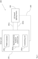
- the method 100 may comprise the step of feeding back a signal 203 to the driver unit 201 representing an actual long time average value of the current through the LED based lighting means 202 (see also Fig. 2 ).
- Fig. 2 shows an embodiment of a driver unit 201 for LED based lighting means 202.
- the driver unit 201 for LED based lighting means 202 comprises:
- the LED based lighting means 202 can be a device which comprises one or more LEDs.
- the driver unit 201 can be configured to provide a nominal or target value for the long-term average value of the current through the LED lighting means 202.
- the driver unit 201 can be configured to translate this nominal value, e.g., by mapping or by a function implemented in the diver unit 201, into a duty cycle of a PWM modulation of the current (in case of feedforward control). Alternatively or additionally, the driver unit 201 can be configured to compare the nominal value to an actually measured long-term average value of the current through the LED lighting means 202. The driver unit 201 can further comprise a feedback control unit configured to translate any deviation in this comparison to a duty cycle of the PWM modulation. Thus, in both cases, a duty cycle and a set frequency for the PWM modulation are given.
- the driver unit 201 in particular the modulating unit 201e, can be configured to modulate the on-time or off-time such that a spectrum of the current through the LED based lighting means 202 comprises both a DC and an AC component.
- the AC component can have a frequency of greater than 60 Hz, preferably greater than 80 Hz, more preferably greater than 100 Hz. In this way, flickering effects visible to the human eye can be avoided, as explained above.
- the PWM modulator 201c of the driver unit 201 can be a sigma-delta modulator.
- black/white stripes or similar effects can be avoided in photos or videos which are captured in an area which is illuminated by the LED based lighting means 202.
- the photos or videos can be captured by a camera of a smartphone.
- the LED based lighting means 202 can be installed in the area, e.g. to provide an ambient illumination of the area.
Landscapes
- Circuit Arrangement For Electric Light Sources In General (AREA)
Priority Applications (1)
| Application Number | Priority Date | Filing Date | Title |
|---|---|---|---|
| EP22188455.4A EP4319488A1 (fr) | 2022-08-03 | 2022-08-03 | Fonctionnement d'un moyen d'éclairage à del |
Applications Claiming Priority (1)
| Application Number | Priority Date | Filing Date | Title |
|---|---|---|---|
| EP22188455.4A EP4319488A1 (fr) | 2022-08-03 | 2022-08-03 | Fonctionnement d'un moyen d'éclairage à del |
Publications (1)
| Publication Number | Publication Date |
|---|---|
| EP4319488A1 true EP4319488A1 (fr) | 2024-02-07 |
Family
ID=82786466
Family Applications (1)
| Application Number | Title | Priority Date | Filing Date |
|---|---|---|---|
| EP22188455.4A Pending EP4319488A1 (fr) | 2022-08-03 | 2022-08-03 | Fonctionnement d'un moyen d'éclairage à del |
Country Status (1)
| Country | Link |
|---|---|
| EP (1) | EP4319488A1 (fr) |
Citations (1)
| Publication number | Priority date | Publication date | Assignee | Title |
|---|---|---|---|---|
| US20180084616A1 (en) * | 2016-09-16 | 2018-03-22 | Lutron Electronics Co., Inc. | Load Control Device for a Light-Emitting Diode Light Source Having Different Operating Modes |
-
2022
- 2022-08-03 EP EP22188455.4A patent/EP4319488A1/fr active Pending
Patent Citations (1)
| Publication number | Priority date | Publication date | Assignee | Title |
|---|---|---|---|---|
| US20180084616A1 (en) * | 2016-09-16 | 2018-03-22 | Lutron Electronics Co., Inc. | Load Control Device for a Light-Emitting Diode Light Source Having Different Operating Modes |
Similar Documents
| Publication | Publication Date | Title |
|---|---|---|
| US9491823B2 (en) | Lighting device, lighting fixture and lighting system | |
| US9235109B2 (en) | Light source driving device, light source driving method, and image display device | |
| TWI418239B (zh) | 發光二極體之驅動電路、調光器及其方法 | |
| US9979477B2 (en) | Method for driving a light source, a driver system to drive a light source and a luminaire comprising said light source and driver system | |
| CN101836505A (zh) | Led调光装置 | |
| JP2011108671A (ja) | Led調光装置 | |
| US9066387B2 (en) | Method and apparatus for regulating the brightness of light-emitting diodes | |
| US9852680B2 (en) | Projection type display device and method for controlling operation of projection type display device | |
| EP4319488A1 (fr) | Fonctionnement d'un moyen d'éclairage à del | |
| KR101021780B1 (ko) | 발광다이오드 교류위상제어 구동장치 | |
| EP3803507B1 (fr) | Pilote de del et procédé de fonctionnement d'une caméra | |
| JP2013246974A (ja) | 点灯装置及びそれを用いた照明器具 | |
| JP2016009625A (ja) | 照明制御装置、照明装置並びに照明器具 | |
| US12520400B2 (en) | Multi-channel driver with switchable by pass capacitors | |
| EP2107419A1 (fr) | Dispositif d'éclairage pour une utilisation avec une caméra | |
| US8232744B2 (en) | Method for the operation of and circuit arrangement for light sources | |
| EP1422934B1 (fr) | Méthode de contrôle d'affichage d'image et viseur | |
| US20210381681A1 (en) | Illuminating System and Luminance Adjusting Method thereof | |
| JP2009244809A (ja) | 画像表示装置 | |
| KR20080109776A (ko) | 조명장치 및 조명장치를 구비한 디스플레이 시스템 | |
| TW201429301A (zh) | 調光電路及應用其之發光裝置 | |
| CA2949362A1 (fr) | Source de lumiere synchronisee pour imageurs du type a "volet roulant" | |
| JP2020027752A (ja) | 点灯装置及びそれを用いた照明器具 | |
| JP2011165496A (ja) | 点灯装置 |
Legal Events
| Date | Code | Title | Description |
|---|---|---|---|
| PUAI | Public reference made under article 153(3) epc to a published international application that has entered the european phase |
Free format text: ORIGINAL CODE: 0009012 |
|
| STAA | Information on the status of an ep patent application or granted ep patent |
Free format text: STATUS: THE APPLICATION HAS BEEN PUBLISHED |
|
| AK | Designated contracting states |
Kind code of ref document: A1 Designated state(s): AL AT BE BG CH CY CZ DE DK EE ES FI FR GB GR HR HU IE IS IT LI LT LU LV MC MK MT NL NO PL PT RO RS SE SI SK SM TR |
|
| STAA | Information on the status of an ep patent application or granted ep patent |
Free format text: STATUS: REQUEST FOR EXAMINATION WAS MADE |
|
| 17P | Request for examination filed |
Effective date: 20240404 |
|
| RBV | Designated contracting states (corrected) |
Designated state(s): AL AT BE BG CH CY CZ DE DK EE ES FI FR GB GR HR HU IE IS IT LI LT LU LV MC MK MT NL NO PL PT RO RS SE SI SK SM TR |