EP4319640B1 - Personalisierte bildgebung in der intesivpflege - Google Patents
Personalisierte bildgebung in der intesivpflege Download PDFInfo
- Publication number
- EP4319640B1 EP4319640B1 EP22718459.5A EP22718459A EP4319640B1 EP 4319640 B1 EP4319640 B1 EP 4319640B1 EP 22718459 A EP22718459 A EP 22718459A EP 4319640 B1 EP4319640 B1 EP 4319640B1
- Authority
- EP
- European Patent Office
- Prior art keywords
- patient
- ray
- images
- image
- radiographic
- Prior art date
- Legal status (The legal status is an assumption and is not a legal conclusion. Google has not performed a legal analysis and makes no representation as to the accuracy of the status listed.)
- Active
Links
Images




Classifications
-
- A—HUMAN NECESSITIES
- A61—MEDICAL OR VETERINARY SCIENCE; HYGIENE
- A61B—DIAGNOSIS; SURGERY; IDENTIFICATION
- A61B6/00—Apparatus or devices for radiation diagnosis; Apparatus or devices for radiation diagnosis combined with radiation therapy equipment
- A61B6/04—Positioning of patients; Tiltable beds or the like
-
- A—HUMAN NECESSITIES
- A61—MEDICAL OR VETERINARY SCIENCE; HYGIENE
- A61B—DIAGNOSIS; SURGERY; IDENTIFICATION
- A61B6/00—Apparatus or devices for radiation diagnosis; Apparatus or devices for radiation diagnosis combined with radiation therapy equipment
- A61B6/48—Diagnostic techniques
- A61B6/486—Diagnostic techniques involving generating temporal series of image data
-
- A—HUMAN NECESSITIES
- A61—MEDICAL OR VETERINARY SCIENCE; HYGIENE
- A61B—DIAGNOSIS; SURGERY; IDENTIFICATION
- A61B6/00—Apparatus or devices for radiation diagnosis; Apparatus or devices for radiation diagnosis combined with radiation therapy equipment
- A61B6/52—Devices using data or image processing specially adapted for radiation diagnosis
- A61B6/5211—Devices using data or image processing specially adapted for radiation diagnosis involving processing of medical diagnostic data
- A61B6/5217—Devices using data or image processing specially adapted for radiation diagnosis involving processing of medical diagnostic data extracting a diagnostic or physiological parameter from medical diagnostic data
-
- A—HUMAN NECESSITIES
- A61—MEDICAL OR VETERINARY SCIENCE; HYGIENE
- A61B—DIAGNOSIS; SURGERY; IDENTIFICATION
- A61B6/00—Apparatus or devices for radiation diagnosis; Apparatus or devices for radiation diagnosis combined with radiation therapy equipment
- A61B6/54—Control of apparatus or devices for radiation diagnosis
- A61B6/545—Control of apparatus or devices for radiation diagnosis involving automatic set-up of acquisition parameters
-
- A—HUMAN NECESSITIES
- A61—MEDICAL OR VETERINARY SCIENCE; HYGIENE
- A61B—DIAGNOSIS; SURGERY; IDENTIFICATION
- A61B6/00—Apparatus or devices for radiation diagnosis; Apparatus or devices for radiation diagnosis combined with radiation therapy equipment
- A61B6/54—Control of apparatus or devices for radiation diagnosis
- A61B6/547—Control of apparatus or devices for radiation diagnosis involving tracking of position of the device or parts of the device
-
- A—HUMAN NECESSITIES
- A61—MEDICAL OR VETERINARY SCIENCE; HYGIENE
- A61B—DIAGNOSIS; SURGERY; IDENTIFICATION
- A61B6/00—Apparatus or devices for radiation diagnosis; Apparatus or devices for radiation diagnosis combined with radiation therapy equipment
- A61B6/58—Testing, adjusting or calibrating thereof
- A61B6/587—Alignment of source unit to detector unit
-
- A—HUMAN NECESSITIES
- A61—MEDICAL OR VETERINARY SCIENCE; HYGIENE
- A61B—DIAGNOSIS; SURGERY; IDENTIFICATION
- A61B6/00—Apparatus or devices for radiation diagnosis; Apparatus or devices for radiation diagnosis combined with radiation therapy equipment
- A61B6/58—Testing, adjusting or calibrating thereof
- A61B6/588—Setting distance between source unit and detector unit
-
- G—PHYSICS
- G16—INFORMATION AND COMMUNICATION TECHNOLOGY [ICT] SPECIALLY ADAPTED FOR SPECIFIC APPLICATION FIELDS
- G16H—HEALTHCARE INFORMATICS, i.e. INFORMATION AND COMMUNICATION TECHNOLOGY [ICT] SPECIALLY ADAPTED FOR THE HANDLING OR PROCESSING OF MEDICAL OR HEALTHCARE DATA
- G16H40/00—ICT specially adapted for the management or administration of healthcare resources or facilities; ICT specially adapted for the management or operation of medical equipment or devices
- G16H40/40—ICT specially adapted for the management or administration of healthcare resources or facilities; ICT specially adapted for the management or operation of medical equipment or devices for the management of medical equipment or devices, e.g. scheduling maintenance or upgrades
-
- A—HUMAN NECESSITIES
- A61—MEDICAL OR VETERINARY SCIENCE; HYGIENE
- A61B—DIAGNOSIS; SURGERY; IDENTIFICATION
- A61B6/00—Apparatus or devices for radiation diagnosis; Apparatus or devices for radiation diagnosis combined with radiation therapy equipment
- A61B6/04—Positioning of patients; Tiltable beds or the like
- A61B6/0492—Positioning of patients; Tiltable beds or the like using markers or indicia for aiding patient positioning
-
- A—HUMAN NECESSITIES
- A61—MEDICAL OR VETERINARY SCIENCE; HYGIENE
- A61B—DIAGNOSIS; SURGERY; IDENTIFICATION
- A61B6/00—Apparatus or devices for radiation diagnosis; Apparatus or devices for radiation diagnosis combined with radiation therapy equipment
- A61B6/58—Testing, adjusting or calibrating thereof
- A61B6/589—Setting distance between source unit and patient
Definitions
- the disclosure relates generally to digital radiographic imaging of the human anatomy and more particularly to solutions for improving patient care and treatment protocol in critical care situations according to monitoring of image contents over time.
- ICU intensive care unit
- change assessment derived from ongoing, longitudinal monitoring of the patient's health status, provides a useful basis for caregiver assessment of, and refinement to, treatment protocol.
- ICU intensive care unit
- components to longitudinal monitoring of patients in the ICU including vital signs monitoring, tracking symptoms such as blood pressure, heartrate (EKG), and breathing patterns, for example.
- histological and imaging data, as well as visual and audio cues can be integral to effective health status monitoring.
- Imaging using x-rays can be an effective tool in change assessment of a patient's condition.
- patients in the Intensive Care Unit (ICU) who suffer from severe cardio-pulmonary disfunction, such as due to pneumonia or heart failure, are routinely monitored using chest x-rays.
- Chest x-ray images allow the attending team to evaluate disease progression or response to a course of treatment, as evidenced by lung opacifications.
- Clinical assessment of changes in the lungs can be obtained by comparing the current x-ray with a recent prior x-ray.
- the clinician can observe changes in opacification between most current and next recent images, and judge how much change there is in the patient condition, with image content evaluated to indicate improvement, worsening, or relative stability. For instance, imaging with x-rays provides indication of fluid levels in the lungs, and thus helps in tracking fluid level changes, such as in comparison between newly acquired images and prior images.
- Treatment refinement is an intrinsically reactive process, as progression or recession of disease, such as can be evidenced by fluid level increase or decrease within the lungs, can be determined based on an assessment of (or change in) the patient condition in response to the given treatment.
- Treatment refinements may include drug dosage changes, insertion or removal of catheters, and refinements of respirator settings, for example.
- X-ray imaging in the contemporary ICU is performed by radiographic technologists using mobile x-ray imaging devices, e.g., mobile digital radiography (mDR) systems, such as the DRX Revolution Mobile Imaging System from Carestream Health, Rochester, NY.
- mDR mobile digital radiography
- a key factor in assessing changes in patient health based on x-ray images relates to the consistency of image capture parameters between a newly acquired x-ray image and a prior x-ray image or set of prior x-ray images. For instance, when comparing images, it is useful to know whether or not the same exposure techniques were followed, whether the same patient positioning and acquisition geometry were used, and, for chest x-ray images, whether the acquisition was performed with the patient in the same phase of a breathing cycle. Inconsistencies in capture geometry and image processing parameters can make it challenging to differentiate changes in image acquisition factors from actual changes in patient health condition.
- the two x-ray images 62, 64 in FIG. 1 were obtained from the same patient at different phases of the breathing cycle, which breathing cycle is represented by a graph 60, where full inspiration is indicated at a peak of the cycle (e.g. image 64) and full expiration is indicated at a trough of the cycle (e.g. image 62), making it difficult to identify incremental changes in patient condition.
- a peak of the cycle e.g. image 64
- trough of the cycle e.g. image 62
- US 2015 / 265 219 A1 discloses a method for adapting a medical system to an object movement during medical examination of the object and a medical system configured for carrying out the method.
- the medical system has a device for detecting and quantifying a motion of the object before or during an acquisition of diagnostic data.
- the system for detecting and quantifying a motion of the object identifies and qualifies the occurrence of object motion and to automatically suggest an adaptation of the diagnostic data acquisition strategy/technique as a function of the object motion.
- US 2015 / 216 450 A1 relates to a patient monitor for detecting patient movement or abnormal breathing. Images of a patient are obtained by a stereoscopic camera.
- An object of the present disclosure is to address the need to maintain more effective ongoing monitoring of patient condition using consistent radiographic imaging factors and appropriate timing based on changes in the patient condition.
- a system and method to improve the consistency of capture of x-ray images of the same patient in an ICU or other critical care facility at different moments in time a plurality of radiographic images of a patient are captured using a common geometric relationship with respect to an x-ray source, the patient and a digital detector. A change in the patient's health is assessed based on the radiographic images of the patient and a time to capture a next radiographic image of the patient is automatically scheduled, using the common geometric relationship.
- the term "energizable” relates to a device or set of components that perform an indicated function upon receiving power and, optionally, upon receiving an enabling signal. The opposite state of “energizable” is “disabled”.
- actuable has its conventional meaning, relating to a device or component that is capable of effecting an action in response to a stimulus, such as in response to an electrical signal, for example.
- modalities is a term of art that refers to types of imaging. Modalities for a radiographic imaging system may be conventional x-ray, serial radiography or video x-ray, fluoroscopy, tomosynthesis, tomography, dual-energy, or other types of imaging that employ ionizing radiation directed through patient anatomy to a detector. Thus, references herein to "radiographic imaging” and “radiographic imaging apparatus” can apply for conventional x-ray, serial radiography, video x-ray, fluoroscopy, tomosynthesis, tomography, dual-energy, or other types of imaging using x-ray energy.
- subject refers to the patient who is being imaged and, in optical terms, can be considered equivalent to the "object" of the corresponding imaging system.
- Coupled is intended to indicate a mechanical association, connection, relation, or linking, between two or more components, such that the disposition of one component affects the spatial disposition of a component to which it is coupled.
- two components need not be in direct contact, but can be linked through one or more intermediary components or fields.
- set refers to a non-empty set, as the concept of a collection of elements or members of a set is widely understood in elementary mathematics.
- subset unless otherwise explicitly stated, is used herein to refer to a non-empty proper subset, that is, to a subset of the larger set, having one or more members.
- a subset may comprise the complete set S.
- a "proper subset" of set S is strictly contained in set S and excludes at least one member of set S.
- signal communication means that two or more devices and/or components are capable of communicating with each other in at least one direction via signals that travel over some type of signal path.
- Signal communication may be wired or wireless.
- the signals may be communication, power, data, or energy signals which may communicate information, power, and/or energy from a first device and/or component to a second device and/or component along a signal path between the first device and/or component and second device and/or component.
- the signal paths may include physical, electrical, magnetic, electromagnetic, optical, wired, and/or wireless connections between the first device and/or component and second device and/or component.
- the signal paths may also include additional devices and/or components between the first device and/or component and second device and/or component.
- Embodiments of the present disclosure help to enable personalized imaging for the ICU patient, taking advantage of information that may be routinely obtained in order to more efficiently schedule and use x-ray modalities and to help limit radiation exposure according to information specifically obtained from a patient.
- changes in patient condition can be predicted by trending change vectors that are derived from multiple x-ray images captured consistently and, further, from combinations of x-ray images with other data, such as vital signs metrics, that may be available. Further, mathematical models derived from trending data can be utilized to determine if and when a subsequent image of the patient should be acquired.
- a subsequent image may be indicated and, according to an embodiment of the present disclosure, captured automatically or prompted at a predetermined point in time or at a predetermined respiratory phase.
- the trending model indicates that the patient is improving or indicates a stable condition
- subsequent x-ray imaging may be scheduled or advised at a later time, depending on the analysis.
- the aforementioned sequence represents, by way of example, a method for optimizing the radiation dose delivered to the patient and, at the same time, optimizing image and information capture factors for providing effective treatment and care to the patient.
- Consistent and precise image capture and processing may be difficult using mDR.
- a new paradigm for ICU patient imaging can be leveraged to improve patient care, particularly in an ICU environment configured with mobile x-ray imaging equipment.
- the in-room x-ray equipment can be configured in a number of different ways that can enable highly consistent image capture.
- consistent image capture can be used to help improve automated exam triggering.
- Consistency can be achieved through automated, remote-virtual, or technologist-assisted positioning of the x-ray tube and the collimator with respect to the patient anatomy to be imaged, e.g., the chest, and the imaging receptor, which is typically a flat panel digital radiography detector.
- automated, virtual, or technologist assisted positioning may be achieved using a stereoscopic visible light camera system mounted to an x-ray tube head, coupled with various fiducial markers, wherein the acquisition technique settings, such as kVp and mAs settings can be determined using a body mass index or other surrogate for patient anatomy thickness.
- acquisition technique settings such as kVp and mAs settings
- body mass index or other surrogate for patient anatomy thickness can be used instead of a stereoscopic light camera.
- Other aspects of the imaging geometry can be configured in a manner that is consistent with prior images of the same patient.
- the stereoscopic camera is used to precisely measure the phase of the respiratory cycle and thereby be used as one indication (trigger) for performing an exposure.
- Other methods for respiratory gating may be used as well, for instance, audio sensing or other sensing for detecting patient movement relating to the breathing cycle.
- Embodiments of the present disclosure address the need for improved radiographic image consistency with solutions that can be applied over a broad range of image modalities.
- An area of particular need that can be addressed by employing solutions described herein relates to image consistency in the ICU and other critical care facilities in which periodic monitoring of patient condition includes repeated radiographic imaging sessions that capture images of the same anatomic region.
- the chest x-ray as shown in the examples of FIG. 1 , is widely used for ICU patients, embodiments described herein describe how solutions of the present disclosure can be implemented using the example of periodic chest x-rays.
- Embodiments of the present disclosure are not limited to chest x-rays, however, and other applications for patient conditions, anatomy, and imaging modes not specifically described herein can be apparent to those skilled in the radiographic imaging arts.
- FIG. 2 shows an exemplary arrangement of imaging components that can be used to form a radiographic imaging apparatus 10 and can help to provide consistent imaging results.
- a patient P is disposed on a bed or other support platform 12 that has radio-translucent regions to allow image acquisition.
- An x-ray source 14 with a motorized x-ray collimator 26 directs radiation to a digital detector 16, with the emitted radiation energy represented by a central ray 18.
- Central ray 18 is preferably orthogonal to the planar incident surface of detector 16.
- a translation apparatus 20, such as an x-y stage driven by actuator 22, provides motion for suitably positioning detector 16 for receiving incident radiation that is conveyed through and near to the patient anatomy of interest.
- Detector 16 is in signal communication with a control logic processor 40.
- Image-bearing signals from detector 16 are sent to control logic processor 40.
- the signal data content can then be locally rendered on a display 24 that is in signal communication with processor 40.
- Control logic processor 40 has a memory 44 for storing acquisition parameters and acquired image data content.
- the image data content can also be transmitted to one or more networked processors 42 for further processing and storage.
- a number of sensors can provide information that is needed to support automated positioning of imaging components or, alternately, to provide feedback to control logic processor 40 that guides manual positioning.
- an inclinometer 28 can be used to sense the relative inclination angle of detector 16.
- a camera 30 can be used to obtain reflectance images that show the relative alignment of x-ray source 14 to the patient anatomy. Camera 30 images can be used to detect one or more fiducials (not shown), used by processor 40 logic for positioning information. Camera 30 can be a stereoscopic camera, as described previously.
- An actuator 32 provides angular and x- and y- axis translational movement in the plane of detector 16 (as shown by conventional x, y, and z axes in FIG. 1 ) for guiding the path of radiation from x-ray source 14 from the x-ray tube.
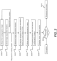
- the logic flow diagram of FIG. 3 shows a processing sequence for automated scheduling, maintaining consistent rendering for radiographic images by tracking and controlling various factors that affect image appearance, geometry, and image-to-image registration according to an embodiment of the present disclosure.
- a first radiographic image is obtained, having an associated set of acquisition factors.
- a recording step S210 is executed, in which the set of acquisition factors or parameters used for the first image are recorded in memory as a set of acquisition settings and linked with the obtained first image and with the patient ID.
- the recorded acquisition factor data is then available for future use.
- Exemplary acquisition factors that can be recorded as the set of acquisition settings can include the following:
- identification of the patient and type of exam needed can activate a retrieval step S220 in which the recorded acquisition factor data, as noted previously, can be accessed from memory and used to set up and monitor the positioning of the imaging apparatus for acquiring a second radiographic image in a configuration step S230.
- the imaging system logic can directly control one or more actuators that automatically set up the system configuration. Operator override of automated setup and monitoring can be provided.
- the subsequent image can be obtained in an acquisition step S240.
- the first and subsequent images can be combined and compared in a processing step S250.
- Various types of automated processing can be provided, using programmed or machine learning logic.
- subtraction can be applied, pixel by pixel, in order to ascertain how much difference there is between the images and to show more detailed information on patient condition. Subsequent description provides more detailed information on processing logic and options.
- an operator interface on display 24 can provide text, graphical, or audible instructions to guide manual adjustment of source and detector position.
- the operator interface can also provide data for technique settings and other information for use by the operator in configuring the imaging apparatus for obtaining consistent imaging results for subsequent images, based on stored configuration parameter data for previous images.
- Feedback from sensor detection can help to guide operator adjustment, indicating that dimensional or angular positioning does not match that used for previous exams and suggesting remedial modification, for example.
- Feedback sensing can be continuous as adjustments are made, in order to help fine-tune the positioning geometry, for example.
- the sequence of FIG. 3 can be used for a wide variety of x-ray modalities, including conventional 2D radiographic imaging, tomosynthesis and other volume imaging and depth imaging modes, serial radiography or "video x-ray" imaging.
- a rendering step S260 appropriately displays or transmits the newly acquired imaging data.
- embodiments may include using limited angle digital tomosynthesis captured images, serial radiography, general conventional x-ray radiographs, dynamic digital tomosynthesis, and dual energy captured images.
- a verification step S264 determines whether or not a subsequent exam should be scheduled and determines a suitable time interval. If needed, a scheduling step S270 then schedules a subsequent exam based on the assessment of patient condition. If a subsequent exam is not needed, no further action is taken.
- Using the same image technique settings can be particularly useful for obtaining consistency. Differences in these settings can change the appearance of lung disease, such as pneumonia or pulmonary edema, for example. Consistent grayscale presentation can help to identify various patient conditions.
- serial radiography Using serial radiography, a set of images is acquired, with the series of images sequentially obtained spanning the breathing cycle, for example.
- Serial radiography can be an effective imaging mode for capture of the repeated breathing cycle at successive phases.
- the timing diagram graph 60 of FIG. 4 shows, in simplified form, a representative portion of the normal breathing cycle, with recurring periods of inspiration and expiration. Exemplary instants of the cycle are labeled Q1, Q2, ... Q5 for illustration. It can be appreciated that the appearance and positioning of lung features for images captured at full inspiration, such as those captured with patient breathing at instants Q3 or Q4 for example, would differ from the appearance and positioning for images captured at or near full expiration, such as at instant Q5 in FIG. 4 .
- timing data relative to the breathing cycle can be stored for images in a first series in step S210, as described previously with reference to FIG. 3 .
- the relative timing of image captures to the breathing cycle can be tracked and recorded, allowing a close match between serial images of the first set, as described previously, and corresponding images of the subsequent series.
- the timing of subsequent session can be matched to the timing of the first serial session.
- acquisition of image content for both the first series of images and the second series of images can be triggered according to the patient breathing pattern, such as at full inspiration, or other suitable trigger condition related to movement of the patient, further allowing the two breathing sequences to be compared, as well as facilitating the comparison of any two images taken at the same phase of the breathing cycle in each of their respective sessions.
- Tracking of the patient breathing cycle can be performed using camera 30 ( FIG. 1 ) that obtains reflectance images or a separate camera or sensor.
- a camera could be used, for example, to monitor patient breathing from the same position.
- camera 30 can have depth measurement capability, such as that available using a LIDAR camera such as the REALSENSE(TM) LIDAR Camera from Intel(R).
- depth data can be obtained using an RGB-D color depth camera such as the time-of-flight AZURE KINECT DK depth camera from Microsoft.
- processor 40 can control timing of single-mode x-ray images as well as timing to initiate serial radiography or correlate individual serial radiography series images.
- the breathing cycle can be stored as part of the patient record, for example.
- Additional aspects may include temporal, grayscale and geometric registration of a more recent captured motion sequence with one or more prior series and leveraging pseudo-invariant features as tie, or anchor, points, i.e., features within the image that remain reasonably (pseudo) invariant to the breathing motion, while registering the other structures that vary in position and grayscale significantly during the breathing cycle.
- pseudo-invariant features as tie, or anchor, points, i.e., features within the image that remain reasonably (pseudo) invariant to the breathing motion, while registering the other structures that vary in position and grayscale significantly during the breathing cycle.
- an ICU room-based imaging system may facilitate the capture of higher dimensional imagery, with greater than 2-dimensions, such as temporal (dynamic) x-ray, spectral (dual energy) imaging, and 3D-spatial (digital tomosynthesis) x-ray capture of critically ill patients in the ICU.
- Such x-ray imaging is more challenging when using mDR.
- a system and/or method for the capture of 2D dynamic x-ray acquisition is disclosed using more than one perspective.
- dynamic x-ray sequences can be captured from two perspectives---such as AP (anteroposterior) and an oblique view.
- the capture of the dynamic sequences is synchronized in time and, as such, the dynamic sequences are synchronized with respect to the phase of the patient's breathing cycle.
- two DR detectors and two x-ray sources can be used.
- either one detector and x-ray tube or multiple detectors and tubes can be systematically moved about the patient anatomy during image capture in a precise, calibrated manner, such that a greater number of dynamic perspectives are captured during the acquisition sequence. Images captured in this synchronized dynamic sequence can be processed to produce a pseudo-3D motion sequence of the patient, for example, representing the patient's full breathing cycle.
- image analysis can be provided by a comparison of images taken in different exam sessions. Automated comparison can be particularly effective where the compared images have been captured using consistent geometry and acquisition settings.
- a deep-learning based analysis of related physiologic imaging exams can be used to compare prior images with more recent images in order to identify a change in a patient's condition (e.g., improved or worsened) and a magnitude of the change.
- the amount of change in patient condition can be simply expressed, such as numerically rated from 0-10 in a simpler embodiment.
- the relative degree of patient change can be expressed as a more complex data vector that provides multi-dimensional data and patient measurements.
- a severity of a patient's condition may be quantified, e.g., automatically generating an overall severity score for lung opacification.
- Prognostics generated from the automated analysis can include probability of needing intubation within the next X number of days, probability of mortality within the next X number of days, or other likely outcomes.
- machine learning can also be used for providing initial setup of acquisition parameters, given various information about the patient condition.
- Automated analysis has the advantage of using patient history and other data that may not be easily accessible to the practitioner, in addition to using learned data from imaging other patients.
- methods described herein can be useful for any of the radiographic modalities, including fluoroscopy, wherein repositioning to align geometry of imaging apparatus and the patient may be particularly important.
- methods of the present disclosure can be useful for imaging modalities that require use of a mobile C-arm, such as the Mobile C-arm System from Carestream Health, Rochester, NY, wherein the imaging signal source needs to be moved in and out of the field in order to provide work-space for the attending practitioner.
- embodiments of the present disclosure simplify the task of providing data for more complex analysis and processing.
- Grayscale correction or normalization can be applied to image content as a tool for providing improved consistency and analysis.
- grayscale correction can be applied in a number of ways, such as by controlling response curves or other transform mechanisms that are used for mapping digital image values to display values.
- rib segmentation may be used for the quantification of respiratory volumes or changes in volumes versus prior images.
- This quantification method may be used as a proxy for tidal volumes or for musculoskeletal breathing recruitment and/or differences thereof versus prior images.
- Processing of the image content from different sessions can include digital subtraction, for example, or other pixel-to-pixel or grouped pixel processing techniques.
- a next exam may be automatically triggered according to analyses of one of more prior exams. Analyses may include assessments of changes in anatomical features, or the degree of changes in abnormal disease processes. For example, dramatic changes in lung opacity can indicate increased fluid content.
- a next exam may also be triggered by an automated program using mathematical models of longitudinally captured prior exams. Triggering of the timing of a next exam, may be either automatically calculated and performed, or may be based on alerts generated by programmed mathematical models, with the actual exam exposure then performed by a radiographic technologist. As an alternative, scheduling of the exam acquisition may default to departmental clinical practice or other standard guidelines.
- comparison step S250 is a key part of the image processing regimen, executing the longitudinal, or time-dimensioned, analysis that provides useful information for assisting in assessing patient condition and treatment requirements.
- the imaging system can act upon processing results that indicate suggested scheduling for subsequent exams in a number of ways.
- the imaging system provides an automatic scheduling capability that displays an imaging timing recommendation, reporting the needed image type, and prompting the radiography staff or attending practitioner when images are needed.
- An exemplary operator interface screen 50 in FIG. 5 shows a reminder prompt 48 that can be displayed.
- Prompt 48 can be rendered in bold, flashing, or otherwise highlighted to catch attention of the staff.
- the automatic scheduling can generate an entry in a computerized scheduling system that is maintained for the attending staff.
- An optional Setup button 52 can be displayed, allowing the viewer to display a listing of stored acquisition settings associated with the image, including type of image needed and parameters for consistent acquisition geometry and technique settings.
- Various types of scheduling software can be executing in the ICU or general hospital environment. Signals provided by the apparatus of the present disclosure can be used to interface with existing scheduling systems and to enter scheduling requests with or without operator intervention, depending on the particular requirements of the medical care facility.
- the scheduled image capture can be automatically executed, with set up for imaging performed by the imaging apparatus and approval or other acknowledgement to initiate exposure entered by the attending staff.
- Mathematical models to assist in exam scheduling can be generated, in whole or in part, using machine learning techniques.
- Feature vectors for training and for decision-making can be formed based not only on image comparison, but also including vital signs and patient history data, as well as the set of image acquisition settings as outlined above, for example.
- the system can provide an interim, temporal monitoring capability by capturing scout or sampling images, such as projection radiographs at very low dose levels and/or at low spatial resolution. Taken at regular intervals between exams, scout images can also be obtained using consistent image acquisition geometry, consistent technique settings, and, for chest x-rays, with similar timing with respect to the respiratory cycle of the patient.
- scout images can also be obtained using consistent image acquisition geometry, consistent technique settings, and, for chest x-rays, with similar timing with respect to the respiratory cycle of the patient.
- the low dose or low spatial resolution images can be monitored, either automatically or with human assistance, for gross changes in patient respiratory status, or other changes commensurate with the reduced spatial, signal-to noise, or grayscale resolution imaging.
- models can be developed that either automatically trigger the appropriate (indicated) high-resolution exam.
- the high-resolution exam can be, for example, a standard 2D radiograph.
- the ideal 2D projection can be specified, e.g., AP, oblique, or lateral exposure, a dynamic sequence, a dual energy capture, or a digital tomosynthesis capture.
- the low dose temporal sampling may be performed from a consistent view projection, a stratified sampling of view projections, or from a randomized sampling of view projections.
- a computer program product may include one or more storage medium, for example; magnetic storage media such as magnetic disk (such as a floppy disk) or magnetic tape; optical storage media such as optical disk, optical tape, or machine readable bar code; solid-state electronic storage devices such as random access memory (RAM), or read-only memory (ROM); or any other physical device or media employed to store a computer program having instructions for controlling one or more computers to practice the method according to the present invention.
- magnetic storage media such as magnetic disk (such as a floppy disk) or magnetic tape
- optical storage media such as optical disk, optical tape, or machine readable bar code
- solid-state electronic storage devices such as random access memory (RAM), or read-only memory (ROM); or any other physical device or media employed to store a computer program having instructions for controlling one or more computers to practice the method according to the present invention.
Landscapes
- Health & Medical Sciences (AREA)
- Life Sciences & Earth Sciences (AREA)
- Engineering & Computer Science (AREA)
- Medical Informatics (AREA)
- Biomedical Technology (AREA)
- Public Health (AREA)
- General Health & Medical Sciences (AREA)
- Heart & Thoracic Surgery (AREA)
- High Energy & Nuclear Physics (AREA)
- Pathology (AREA)
- Radiology & Medical Imaging (AREA)
- Nuclear Medicine, Radiotherapy & Molecular Imaging (AREA)
- Physics & Mathematics (AREA)
- Molecular Biology (AREA)
- Surgery (AREA)
- Animal Behavior & Ethology (AREA)
- Optics & Photonics (AREA)
- Biophysics (AREA)
- Veterinary Medicine (AREA)
- Business, Economics & Management (AREA)
- General Business, Economics & Management (AREA)
- Physiology (AREA)
- Computer Vision & Pattern Recognition (AREA)
- Epidemiology (AREA)
- Primary Health Care (AREA)
- Apparatus For Radiation Diagnosis (AREA)
Claims (9)
- Ein Verfahren, das Folgendes aufweist:Erfassen einer Vielzahl von Röntgenbildern (62, 64) eines Patienten (P), wobei jedes Bild eine gleiche geometrische Beziehung in Bezug auf eine Röntgenquelle (14), den Patienten (P) und einen digitalen Detektor (16), eine gleiche Energie und Intensität eines von der Röntgenquelle (14) emittierten Röntgenstrahls und eine gleiche Phase des Atmungszyklus (Q1, Q2, ... Q5) des Patienten (P) verwendet;Bestimmen einer Änderung in den Röntgenbildern (62, 64) des Patienten (P) auf Grundlage der Vielzahl von erfassten Röntgenbildern (62, 64) des Patienten (P); undautomatisch Planen eines Zeitpunkts zum Erfassen eines nächsten Röntgenbildes (64) des Patienten (P), wobei die Erfassung des nächsten Röntgenbildes (64) unter Verwendung derselben geometrischen Beziehung durchgeführt wird;wobei dieselbe Phase des Atmungszyklus (Q1, Q2, ... Q5) des Patienten (P) unter Verwendung einer stereoskopischen Kamera bestimmt wird, undwobei die Röntgenquelle (14) automatisch zu dem automatisch geplanten Zeitpunkt aktiviert wird, um das nächste Röntgenbild (64) des Patienten (P) in derselben Phase des Atmungszyklus (Q1, Q2, ... Q5) des Patienten (P) aufzunehmen.
- Das Verfahren nach Anspruch 1, das ferner automatisches Aktivieren der Röntgenquelle (14) aufweist, um Dual-Energy- oder 3D-Volumenbilder des Patienten (P) unter Verwendung derselben geometrischen Beziehung zu erfassen.
- Das Verfahren nach Anspruch 2, das ferner Erfassen von Röntgenbildsequenzen des Patienten (P) aus zwei Perspektiven aufweist, und zwar unter gleichzeitiger Verwendung von zwei digitalen Röntgendetektoren (16) und zwei Röntgenquellen (14).
- Das Verfahren nach Anspruch 3, das ferner gleichzeitiges Bewegen der zwei digitalen Röntgendetektoren (16) und der zwei Röntgenquellen (14) aufweist, während eine Vielzahl synchronisierter dynamischer Röntgenbilder (62, 64) des Patienten (P) erfasst wird.
- Das Verfahren nach Anspruch 4, das ferner Verarbeiten der Vielzahl synchronisierter dynamischer Röntgenbilder (62, 64) des Patienten (P) aufweist, um eine 3D-Bewegungssequenz des Patienten (P) zu erzeugen.
- Das Verfahren nach Anspruch 1, wobei das automatische Planen Bereitstellen eines Signals an eine Planungssoftware aufweist, die für die Patientenversorgung (P) verwendet wird.
- Das Verfahren nach Anspruch 1, das ferner elektronisches Speichern von Erfassungsfaktoren aufweist, die dieselbe geometrische Beziehung elektromechanisch definieren.
- Das Verfahren nach Anspruch 7, das ferner elektronisches Abrufen der gespeicherten Erfassungsfaktoren aufweist, um die Röntgenquelle (14) und den digitalen Detektor (16) automatisch in der gemeinsamen geometrischen Beziehung zu positionieren.
- Das Verfahren nach Anspruch 8, das ferner elektronisch Zugreifen auf die gespeicherten Erfassungsfaktoren aufweist, um automatisch dieselbe Energie und Intensität eines von der Röntgenquelle (14) emittierten Röntgenstrahls einzustellen, um die Vielzahl von Röntgenbildern (62, 64) des Patienten (P) aufzunehmen.
Applications Claiming Priority (2)
| Application Number | Priority Date | Filing Date | Title |
|---|---|---|---|
| US202163170594P | 2021-04-05 | 2021-04-05 | |
| PCT/US2022/022975 WO2022216532A1 (en) | 2021-04-05 | 2022-04-01 | Personalized critical care imaging |
Publications (2)
| Publication Number | Publication Date |
|---|---|
| EP4319640A1 EP4319640A1 (de) | 2024-02-14 |
| EP4319640B1 true EP4319640B1 (de) | 2025-06-04 |
Family
ID=81384925
Family Applications (1)
| Application Number | Title | Priority Date | Filing Date |
|---|---|---|---|
| EP22718459.5A Active EP4319640B1 (de) | 2021-04-05 | 2022-04-01 | Personalisierte bildgebung in der intesivpflege |
Country Status (4)
| Country | Link |
|---|---|
| US (1) | US20240180507A1 (de) |
| EP (1) | EP4319640B1 (de) |
| ES (1) | ES3036379T3 (de) |
| WO (1) | WO2022216532A1 (de) |
Family Cites Families (17)
| Publication number | Priority date | Publication date | Assignee | Title |
|---|---|---|---|---|
| WO2006085166A2 (en) * | 2005-01-10 | 2006-08-17 | Koninklijke Philips Electronics N.V. | Lung lesion detection during tomographic heart screening |
| US20080077001A1 (en) * | 2006-08-18 | 2008-03-27 | Eastman Kodak Company | Medical information system for intensive care unit |
| GB2441550A (en) * | 2006-09-05 | 2008-03-12 | Vision Rt Ltd | Surface-imaging breathing monitor |
| US8761864B2 (en) * | 2006-09-14 | 2014-06-24 | General Electric Company | Methods and apparatus for gated acquisitions in digital radiography |
| DE102007026520A1 (de) * | 2007-06-08 | 2008-12-11 | Siemens Ag | Bildakquisitons-, Bildarchivierungs- und Bildrenderingsystem zur Reproduzierung von eingestellten Untersuchungsparametern einer CT-, PET-CT- bzw. MRT- gestützten Erstuntersuchung bei nachfolgenden radiologischen Kontrolluntersuchungen |
| US20130030825A1 (en) * | 2011-07-29 | 2013-01-31 | General Electric Company | Systems and methods for automated triage and scheduling in an emergency department |
| US20130090946A1 (en) * | 2011-10-05 | 2013-04-11 | Thomas Kwok-Fah Foo | Systems and methods for imaging workflow |
| EP2900322A1 (de) * | 2012-09-28 | 2015-08-05 | Brainlab AG | Isozentrische patientenrotation zur detektion der position eines beweglichen objekts |
| US9204853B2 (en) * | 2012-10-11 | 2015-12-08 | Carestream Health, Inc. | Method and system for quantitative imaging |
| EP2921100A1 (de) * | 2014-03-21 | 2015-09-23 | Siemens Aktiengesellschaft | Verfahren zur Anpassung eines medizinisches Systems an die Bewegung des Patienten während einer medizinischen Untersuchung und System dafür |
| EP3034003B1 (de) * | 2014-12-19 | 2017-11-08 | Ion Beam Applications S.A. | Verfahren und Bildgebungssystem zur Bestimmung einer Referenzröntgenaufnahme zur späteren Verwendung bei der Strahlungstherapie |
| US12148521B2 (en) * | 2017-10-30 | 2024-11-19 | Koninklijke Philips N.V. | Closed-loop radiological follow-up recommendation system |
| JP7534038B2 (ja) * | 2018-11-30 | 2024-08-14 | アキュレイ インコーポレイテッド | コーンビームコンピュータ断層撮影における最適なパネル読み出しのための非対称散乱フィッティング |
| DE102019201359A1 (de) * | 2019-02-04 | 2020-08-06 | Siemens Healthcare Gmbh | Planung eines zeitlichen Ablaufs einer medizinischen Untersuchung |
| WO2021141681A1 (en) * | 2020-01-10 | 2021-07-15 | Carestream Health, Inc. | Method amd system to predict prognosis for critically ill patients |
| US11475997B2 (en) * | 2020-02-21 | 2022-10-18 | Shanghai United Imaging Intelligence Co., Ltd. | Systems and methods for automated healthcare services |
| EP4059433A1 (de) * | 2021-03-16 | 2022-09-21 | Koninklijke Philips N.V. | Kontaktlose messung und visualisierung der atmung für thorax-röntgenaufnahmen |
-
2022
- 2022-04-01 EP EP22718459.5A patent/EP4319640B1/de active Active
- 2022-04-01 WO PCT/US2022/022975 patent/WO2022216532A1/en not_active Ceased
- 2022-04-01 US US18/553,586 patent/US20240180507A1/en not_active Abandoned
- 2022-04-01 ES ES22718459T patent/ES3036379T3/es active Active
Also Published As
| Publication number | Publication date |
|---|---|
| US20240180507A1 (en) | 2024-06-06 |
| EP4319640A1 (de) | 2024-02-14 |
| WO2022216532A1 (en) | 2022-10-13 |
| ES3036379T3 (en) | 2025-09-18 |
Similar Documents
| Publication | Publication Date | Title |
|---|---|---|
| US8718338B2 (en) | System and method to compensate for respiratory motion in acquired radiography images | |
| US9743898B2 (en) | Image formation apparatus and method for nuclear imaging | |
| DK2648621T3 (en) | GENERATION OF A SUITABLE MODEL FOR ESTIMATING PATIENT RADIATION DUE TO MEDICAL IMAGE SCANNING | |
| CN101756698B (zh) | 图像诊断装置以及图像处理方法 | |
| KR101775556B1 (ko) | 단층 촬영 장치 및 그에 따른 단층 영상 처리 방법 | |
| US12165314B2 (en) | Method for generating a trained machine learning algorithm | |
| JP2013052233A (ja) | 被検体の配向を決定する方法及び装置 | |
| US20200226779A1 (en) | Radiation imaging device, image processing method, and image processing program | |
| CN111513742A (zh) | 医学成像设备及其控制方法 | |
| JP7073661B2 (ja) | 動態解析装置及び動態解析システム | |
| JP6662428B2 (ja) | 動態解析システム | |
| JP7099086B2 (ja) | 動態画像処理装置及びプログラム | |
| WO2022148688A1 (en) | Navigation support | |
| CN119074019A (zh) | 医学成像方法、装置以及系统 | |
| EP4319640B1 (de) | Personalisierte bildgebung in der intesivpflege | |
| US20180014749A1 (en) | Impedance shift detection | |
| US20100027751A1 (en) | Method for the production of angiography recordings | |
| EP4312773B1 (de) | Physiologische analyse aus videoröntgenbildgebung | |
| EP4434012B1 (de) | Gewichtsschätzung eines patienten | |
| CN114569146B (zh) | 医学图像处理方法、装置、计算机设备及存储介质 | |
| KR20160140189A (ko) | 단층 촬영 장치 및 그에 따른 단층 촬영 방법 | |
| JP7424532B1 (ja) | 放射線画像解析装置及びプログラム | |
| EP4674351A1 (de) | Überprüfung der abtastkonsistenz | |
| EP4636777A1 (de) | Computerimplementiertes verfahren zum betreiben einer medizinischen bildgebungsvorrichtung, medizinische bildgebungsvorrichtung, computerprogramm und elektronisch lesbares speichermedium | |
| EP4491125A1 (de) | Simulierte 4d-ct-überblicke mit 3d-überblick und rgb-d-kamera für verbesserte scan-planung |
Legal Events
| Date | Code | Title | Description |
|---|---|---|---|
| STAA | Information on the status of an ep patent application or granted ep patent |
Free format text: STATUS: UNKNOWN |
|
| STAA | Information on the status of an ep patent application or granted ep patent |
Free format text: STATUS: THE INTERNATIONAL PUBLICATION HAS BEEN MADE |
|
| PUAI | Public reference made under article 153(3) epc to a published international application that has entered the european phase |
Free format text: ORIGINAL CODE: 0009012 |
|
| STAA | Information on the status of an ep patent application or granted ep patent |
Free format text: STATUS: REQUEST FOR EXAMINATION WAS MADE |
|
| 17P | Request for examination filed |
Effective date: 20231027 |
|
| AK | Designated contracting states |
Kind code of ref document: A1 Designated state(s): AL AT BE BG CH CY CZ DE DK EE ES FI FR GB GR HR HU IE IS IT LI LT LU LV MC MK MT NL NO PL PT RO RS SE SI SK SM TR |
|
| DAV | Request for validation of the european patent (deleted) | ||
| DAX | Request for extension of the european patent (deleted) | ||
| GRAP | Despatch of communication of intention to grant a patent |
Free format text: ORIGINAL CODE: EPIDOSNIGR1 |
|
| STAA | Information on the status of an ep patent application or granted ep patent |
Free format text: STATUS: GRANT OF PATENT IS INTENDED |
|
| RIC1 | Information provided on ipc code assigned before grant |
Ipc: A61B 6/58 20240101ALI20241203BHEP Ipc: A61B 6/04 20060101ALI20241203BHEP Ipc: A61B 6/00 20240101AFI20241203BHEP |
|
| INTG | Intention to grant announced |
Effective date: 20241213 |
|
| GRAS | Grant fee paid |
Free format text: ORIGINAL CODE: EPIDOSNIGR3 |
|
| GRAA | (expected) grant |
Free format text: ORIGINAL CODE: 0009210 |
|
| STAA | Information on the status of an ep patent application or granted ep patent |
Free format text: STATUS: THE PATENT HAS BEEN GRANTED |
|
| AK | Designated contracting states |
Kind code of ref document: B1 Designated state(s): AL AT BE BG CH CY CZ DE DK EE ES FI FR GB GR HR HU IE IS IT LI LT LU LV MC MK MT NL NO PL PT RO RS SE SI SK SM TR |
|
| REG | Reference to a national code |
Ref country code: GB Ref legal event code: FG4D |
|
| REG | Reference to a national code |
Ref country code: CH Ref legal event code: EP |
|
| REG | Reference to a national code |
Ref country code: DE Ref legal event code: R096 Ref document number: 602022015502 Country of ref document: DE |
|
| REG | Reference to a national code |
Ref country code: IE Ref legal event code: FG4D |
|
| REG | Reference to a national code |
Ref country code: ES Ref legal event code: FG2A Ref document number: 3036379 Country of ref document: ES Kind code of ref document: T3 Effective date: 20250918 |
|
| REG | Reference to a national code |
Ref country code: NL Ref legal event code: MP Effective date: 20250604 |
|
| PG25 | Lapsed in a contracting state [announced via postgrant information from national office to epo] |
Ref country code: FI Free format text: LAPSE BECAUSE OF FAILURE TO SUBMIT A TRANSLATION OF THE DESCRIPTION OR TO PAY THE FEE WITHIN THE PRESCRIBED TIME-LIMIT Effective date: 20250604 |
|
| REG | Reference to a national code |
Ref country code: LT Ref legal event code: MG9D |
|
| PG25 | Lapsed in a contracting state [announced via postgrant information from national office to epo] |
Ref country code: GR Free format text: LAPSE BECAUSE OF FAILURE TO SUBMIT A TRANSLATION OF THE DESCRIPTION OR TO PAY THE FEE WITHIN THE PRESCRIBED TIME-LIMIT Effective date: 20250905 Ref country code: NO Free format text: LAPSE BECAUSE OF FAILURE TO SUBMIT A TRANSLATION OF THE DESCRIPTION OR TO PAY THE FEE WITHIN THE PRESCRIBED TIME-LIMIT Effective date: 20250904 |
|
| PG25 | Lapsed in a contracting state [announced via postgrant information from national office to epo] |
Ref country code: PL Free format text: LAPSE BECAUSE OF FAILURE TO SUBMIT A TRANSLATION OF THE DESCRIPTION OR TO PAY THE FEE WITHIN THE PRESCRIBED TIME-LIMIT Effective date: 20250604 |
|
| PG25 | Lapsed in a contracting state [announced via postgrant information from national office to epo] |
Ref country code: BG Free format text: LAPSE BECAUSE OF FAILURE TO SUBMIT A TRANSLATION OF THE DESCRIPTION OR TO PAY THE FEE WITHIN THE PRESCRIBED TIME-LIMIT Effective date: 20250604 |
|
| PG25 | Lapsed in a contracting state [announced via postgrant information from national office to epo] |
Ref country code: HR Free format text: LAPSE BECAUSE OF FAILURE TO SUBMIT A TRANSLATION OF THE DESCRIPTION OR TO PAY THE FEE WITHIN THE PRESCRIBED TIME-LIMIT Effective date: 20250604 |
|
| PG25 | Lapsed in a contracting state [announced via postgrant information from national office to epo] |
Ref country code: RS Free format text: LAPSE BECAUSE OF FAILURE TO SUBMIT A TRANSLATION OF THE DESCRIPTION OR TO PAY THE FEE WITHIN THE PRESCRIBED TIME-LIMIT Effective date: 20250904 |
|
| PG25 | Lapsed in a contracting state [announced via postgrant information from national office to epo] |
Ref country code: LV Free format text: LAPSE BECAUSE OF FAILURE TO SUBMIT A TRANSLATION OF THE DESCRIPTION OR TO PAY THE FEE WITHIN THE PRESCRIBED TIME-LIMIT Effective date: 20250604 |
|
| PG25 | Lapsed in a contracting state [announced via postgrant information from national office to epo] |
Ref country code: NL Free format text: LAPSE BECAUSE OF FAILURE TO SUBMIT A TRANSLATION OF THE DESCRIPTION OR TO PAY THE FEE WITHIN THE PRESCRIBED TIME-LIMIT Effective date: 20250604 |
|
| PG25 | Lapsed in a contracting state [announced via postgrant information from national office to epo] |
Ref country code: PT Free format text: LAPSE BECAUSE OF FAILURE TO SUBMIT A TRANSLATION OF THE DESCRIPTION OR TO PAY THE FEE WITHIN THE PRESCRIBED TIME-LIMIT Effective date: 20251006 |
|
| REG | Reference to a national code |
Ref country code: AT Ref legal event code: MK05 Ref document number: 1799562 Country of ref document: AT Kind code of ref document: T Effective date: 20250604 |
|
| PG25 | Lapsed in a contracting state [announced via postgrant information from national office to epo] |
Ref country code: IS Free format text: LAPSE BECAUSE OF FAILURE TO SUBMIT A TRANSLATION OF THE DESCRIPTION OR TO PAY THE FEE WITHIN THE PRESCRIBED TIME-LIMIT Effective date: 20251004 |
|
| PG25 | Lapsed in a contracting state [announced via postgrant information from national office to epo] |
Ref country code: SM Free format text: LAPSE BECAUSE OF FAILURE TO SUBMIT A TRANSLATION OF THE DESCRIPTION OR TO PAY THE FEE WITHIN THE PRESCRIBED TIME-LIMIT Effective date: 20250604 Ref country code: AT Free format text: LAPSE BECAUSE OF FAILURE TO SUBMIT A TRANSLATION OF THE DESCRIPTION OR TO PAY THE FEE WITHIN THE PRESCRIBED TIME-LIMIT Effective date: 20250604 |
|
| PG25 | Lapsed in a contracting state [announced via postgrant information from national office to epo] |
Ref country code: CZ Free format text: LAPSE BECAUSE OF FAILURE TO SUBMIT A TRANSLATION OF THE DESCRIPTION OR TO PAY THE FEE WITHIN THE PRESCRIBED TIME-LIMIT Effective date: 20250604 |
|
| PG25 | Lapsed in a contracting state [announced via postgrant information from national office to epo] |
Ref country code: EE Free format text: LAPSE BECAUSE OF FAILURE TO SUBMIT A TRANSLATION OF THE DESCRIPTION OR TO PAY THE FEE WITHIN THE PRESCRIBED TIME-LIMIT Effective date: 20250604 |
|
| PG25 | Lapsed in a contracting state [announced via postgrant information from national office to epo] |
Ref country code: SK Free format text: LAPSE BECAUSE OF FAILURE TO SUBMIT A TRANSLATION OF THE DESCRIPTION OR TO PAY THE FEE WITHIN THE PRESCRIBED TIME-LIMIT Effective date: 20250604 |
|
| REG | Reference to a national code |
Ref country code: DE Ref legal event code: R081 Ref document number: 602022015502 Country of ref document: DE Owner name: MIDEA IMAGING SINGAPORE PTE. LTD., SG Free format text: FORMER OWNER: CARESTREAM HEALTH, INC., ROCHESTER, NY, US |
|
| REG | Reference to a national code |
Ref country code: GB Ref legal event code: 732E Free format text: REGISTERED BETWEEN 20260205 AND 20260211 |
|
| REG | Reference to a national code |
Ref country code: DE Ref legal event code: R097 Ref document number: 602022015502 Country of ref document: DE |
|
| PLBE | No opposition filed within time limit |
Free format text: ORIGINAL CODE: 0009261 |
|
| STAA | Information on the status of an ep patent application or granted ep patent |
Free format text: STATUS: NO OPPOSITION FILED WITHIN TIME LIMIT |
|
| PG25 | Lapsed in a contracting state [announced via postgrant information from national office to epo] |
Ref country code: DK Free format text: LAPSE BECAUSE OF FAILURE TO SUBMIT A TRANSLATION OF THE DESCRIPTION OR TO PAY THE FEE WITHIN THE PRESCRIBED TIME-LIMIT Effective date: 20250604 |
|
| REG | Reference to a national code |
Ref country code: CH Ref legal event code: L10 Free format text: ST27 STATUS EVENT CODE: U-0-0-L10-L00 (AS PROVIDED BY THE NATIONAL OFFICE) Effective date: 20260416 |