EP4319661B1 - Outil de vissage et procédé d'assemblage utilisant un outil de vissage - Google Patents
Outil de vissage et procédé d'assemblage utilisant un outil de vissage Download PDFInfo
- Publication number
- EP4319661B1 EP4319661B1 EP22717206.1A EP22717206A EP4319661B1 EP 4319661 B1 EP4319661 B1 EP 4319661B1 EP 22717206 A EP22717206 A EP 22717206A EP 4319661 B1 EP4319661 B1 EP 4319661B1
- Authority
- EP
- European Patent Office
- Prior art keywords
- screw
- tool
- tool shaft
- shaft
- screwdriving
- Prior art date
- Legal status (The legal status is an assumption and is not a legal conclusion. Google has not performed a legal analysis and makes no representation as to the accuracy of the status listed.)
- Active
Links
Images


Classifications
-
- A—HUMAN NECESSITIES
- A61—MEDICAL OR VETERINARY SCIENCE; HYGIENE
- A61B—DIAGNOSIS; SURGERY; IDENTIFICATION
- A61B17/00—Surgical instruments, devices or methods
- A61B17/28—Surgical forceps
- A61B17/2812—Surgical forceps with a single pivotal connection
- A61B17/2816—Pivots
-
- A—HUMAN NECESSITIES
- A61—MEDICAL OR VETERINARY SCIENCE; HYGIENE
- A61B—DIAGNOSIS; SURGERY; IDENTIFICATION
- A61B17/00—Surgical instruments, devices or methods
- A61B17/28—Surgical forceps
-
- A—HUMAN NECESSITIES
- A61—MEDICAL OR VETERINARY SCIENCE; HYGIENE
- A61B—DIAGNOSIS; SURGERY; IDENTIFICATION
- A61B17/00—Surgical instruments, devices or methods
- A61B2017/00526—Methods of manufacturing
Definitions
- the present disclosure relates to a screwing tool for transmitting a torque to a screw.
- the present disclosure relates to an assembly method with a, preferably this, screwing tool.
- Such a screwing tool is, for example, from the US 2009 / 0 229 846 A1
- an assembly method for screwing in a screw is known, for example from EP 2 873 381 A1 known.
- the screw is subjected to an axial pressure/axial pressure force by the screwing tool, so that a surface friction force is created between the screwing tool and the screw and when the screwing tool is rotated, a friction torque resulting from the surface friction force is transferred to the screw. If the friction torque between the screwing tool and the screw is smaller than a friction force caused by the thread friction force resulting moment, the screwing tool slips and the screw is not screwed in. This can cause the screwing tool to slip and damage a surface of the screw or a component with the internal thread.
- the screwing tool has a first tool shaft, preferably with a large shaft diameter, and a second tool shaft, preferably with a small shaft diameter.
- the large or small shaft diameter is understood to mean that the shaft diameter of the first tool shaft is larger than the shaft diameter of the second tool shaft.
- the large shaft diameter corresponds approximately to a diameter of the screw head, while the small shaft diameter preferably approximately equal to or smaller than the diameter of a screw shaft or a core diameter of the screw.
- the first tool shaft has an end-side screw engagement section/screw head engagement section, which is provided and designed to transmit a torque to a screw, in particular a screw head of the screw.
- the end-side screw engagement section/screw head engagement section of the first tool shaft can be rotatable and provided and designed to transmit a compressive force axially to the screw, in particular the screw head.
- the second tool shaft has an end-side screw engagement section/screw shaft engagement section, which is provided and designed to transfer a compressive force axially to the screw, in particular a screw end/screw shaft end of the screw opposite the screw head.
- the second tool shaft can be aligned or is aligned axially to the first tool shaft and in the opposite direction to it in such a way that its end-side screw engagement section is axially opposite the end-side screw engagement section of the first tool shaft and is provided and designed to transfer the compressive force axially to the screw in the direction of the first tool shaft.
- the approximately stamp-like first tool shaft and the approximately stamp-like second tool shaft have a common longitudinal axis and are axially spaced from one another such that the screw engagement section of the first tool shaft faces the screw engagement section of the second tool shaft.
- the screw can be arranged in a longitudinally aligned manner between the first tool shaft and the second tool shaft.
- the second tool shaft can be displaced along its longitudinal axis in the direction of the first tool shaft, so that the axially in the direction of the first The compressive force acting towards the tool shaft can be transferred to the screw, and thus from the screw to the first tool shaft. Consequently, a force acting between the screw engagement section of the first tool shaft and the screw corresponds to a sum of the compressive force that can be applied by the first tool shaft and the second tool shaft in the direction of the opposite/counter-rotating tool shaft.
- the screwing tool is provided and designed in such a way that the screw can be clamped axially between the first tool shaft and the second tool shaft.
- This has the advantage that the axial pressure acting between the screwing tool and the screw can be increased by bypassing the internal thread (and thus avoiding an increased thread friction torque).
- the normal force on the surface of the screw, in particular the screw head is increased, while the axial force acting on the screw (as a whole) in the direction of the second tool shaft remains the same or is balanced by the pressure force of the second tool shaft.
- the screwing tool has two separate tool shafts (co-axial) extending axially to one another (on a common axis), a common tool shaft storage frame on which the tool shafts are held (preferably rotatably) and can be moved towards one another in the axial direction in order to axially clamp a screw between them (closed force flow via the tool shaft storage frame, the two tool shafts and the screw clamped between them).
- the clamping force that can be applied axially to the tool shafts via the tool shaft storage frame is preferably adjustable (manually or automatically) (e.g.
- a frictional force is generated between at least one tool shaft on the screw head side (or its screw engagement section) and the screw, which frictional force enables the transmission of a specific screwing torque (from the screw head side tool shank or both tool shanks) onto the screw.
- the screw can be screwed in solely or at least predominantly by frictional force transmission with the screwing tool according to the application, which creates freedom with regard to the design of the screw, in particular the shape of a screw head.
- the screw head can preferably be designed with a flat/unprofiled surface, so that essentially only frictional forces can act between the screw head and the screw engagement section of the tool shaft on the screw head side (which is also preferably unprofiled/does not produce a positive connection), which in particular avoids disadvantages that arise due to an often angular outer or inner profile of the screw head that is necessary for positive force transmission.
- the screw head can be designed to be essentially rotationally symmetrical, which avoids the formation of gaps, slots, pockets or the like, since tissue residues, dirt and body fluids cannot be reliably and completely removed from these when the instrument is reprocessed.
- the screw engagement section of the first tool shaft can have a substantially concavely curved, in particular spherical (smooth/unprofiled) or frustoconical surface.
- the screw engagement section of the first tool shaft can preferably be provided and designed such that the shape of the screw engagement section essentially corresponds to the shape of the screw head.
- the screw head preferably has a substantially convexly curved, in particular spherical (unprofiled) surface.
- the screw engagement section of the second tool shaft can have a substantially flat or concavely curved, in particular spherical (unprofiled) surface, according to a preferred embodiment.
- the screw engagement section of the second tool shaft can preferably be provided and designed such that the shape of the screw engagement section corresponds to the shape of the screw end.
- the screw end preferably has a substantially flat or convexly curved, in particular spherical surface.
- the first tool shaft and/or the second tool shaft can be advantageously guided and centered. Self-centering therefore preferably occurs during assembly or when the screw is clamped between the axially spaced tool shafts.
- a further advantage of the soft-edged/curved surface design of the first tool shaft and/or second tool shaft is that damage when the screwing tool slips and thus any subsequent processing of the screw can be eliminated, which is necessary to ensure the surface quality required for medical, in particular surgical, instruments/devices.
- the present disclosure relates to the screwing tool with a screw which is provided and designed to receive the torque from the screw engagement portion of the first tool shaft and the pressure force from the screw engagement portion of the second tool shaft.
- the screw can have a substantially spherical (or spherical segment-shaped) screw head.
- the screwing tool can have a tightening device (section of the tool shaft storage rack/tool shaft holding device for clamping a screw between the axially spaced tool shafts).
- the tightening device can preferably be provided and designed to adjust a rotation angle and/or the torque of the screw engagement section of the first tool shaft.
- the tightening device can preferably be provided and designed to measure a rotation angle and/or a torque of the screw engagement section of the second tool shaft. It is thus possible to adjust how far and/or how tightly the screw is screwed in (into a medical instrument), i.e.
- the tightening device can be used as a slip clutch to avoid overtightening the screw to be tightened.
- the screwing tool can have a pressure force device (further section of the tool shaft storage frame/tool shaft holding device) (already indicated above).
- the pressure force device is preferably provided and designed to set, calculate and/or measure the pressure force (from the second tool shaft axially in the direction of the first tool shaft onto the screw and/or from the first tool shaft axially in the direction of the second tool shaft onto the screw).
- the pressure force device is preferably provided and designed to set, calculate and/or measure an axial clamping force of the screwing tool acting on the screw.
- the pressure force device can be designed such that an axial distance between the first tool shaft and the second tool shaft can be changed/adjusted, for example by means of a threaded drive, for example against the restoring force of a spring.
- the axial clamping force/axial pressure force can thus be set depending on the length of the screw to be clamped in the screwing tool.
- the pressure force device can be operated manually or, preferably, automatically.
- the first tool shaft and the second tool shaft can be mounted so that they can move axially relative to one another, preferably so that they can be axially displaced or pivoted.
- the screw engagement sections can thus be moved towards and away from one another in a simple manner, for example in the manner of a press or in the manner of pliers.
- the screw engagement section of the first tool shaft can be spring-loaded in the axial direction towards the second tool shaft.
- the screw engagement section of the second tool shaft can be spring-loaded in the axial direction towards the first tool shaft according to a preferred embodiment.
- the first tool shaft can be integrally connected to the second tool shaft so that it can rotate about its longitudinal axis. This means that the second tool shaft also rotates when the first tool shaft rotates. In this way, a torque for screwing in the screw can also be transmitted from the screw engagement section of the second tool shaft to the screw.
- the first tool shaft can be relatively rotatable about its longitudinal axis relative to the second tool shaft. This means that the second tool shaft stands still/does not rotate when the first tool shaft rotates. The second tool shaft therefore only serves as a counter-holder for applying the axial pressure force.
- the second tool shaft can be rotatable about its longitudinal axis independently of the first tool shaft. In this way, a torque can also be applied to the screw via the second tool shaft.
- the screw can first be clamped into the screwing tool before it is inserted into the internal thread and screwed in, or the screw can first be inserted into the internal thread before it is clamped into the screwing tool and screwed in.
- the screw can be secured in its screwed-in position, for example by laser welding and/or by adhesive, which can be applied before clamping into the screwing tool.
- a cleaning-optimised connecting element for surgical instruments which solves the problem of tissue residues accumulating in a slot of the screw, Dirt and bodily fluids can collect and adhere and are not completely removed during the processing process.
- Disadvantages of previous fasteners include that the sharp-edged slot base and slots cannot be reliably cleaned and that assembly errors that are unavoidable in mass production, such as a screwdriver slipping, have to be reworked manually, for example by polishing.
- the task therefore arises of enabling a combination of a design of a fastener head and a suitable assembly process in which there are no deep pockets, slots or the like with sharp edges at the base and the tightening torques/assembly forces applied can be finely adjusted/dosed.
- the screw head and the threaded end can be spherical so that the spherical support guides the system and centers itself when the screw is tightened between its head and the threaded end during the assembly process.
- the force is transmitted via the friction force applied by a tool.
- the tightening torque or the gear or resistance torque of the moving parts can be finely adjusted and/or measured and/or recorded using a sensor.
- the screw connection can be secured in this screw position, if necessary, using adhesive, a laser weld spot or the like. Since the screw head is designed without a slot or a similar force transmission element (positive locking means), the connecting element does not need to be reworked in order to achieve the surface quality required for surgical instruments/devices. This results in process-reliable/reproducible machine manufacturability, simplification of assembly by increasing the degree of mechanization during production and better cleaning properties.
- Figs. 1 to 7 show perspective representations of a section of a screwing tool 1 according to the application at different times of an assembly process carried out with it.
- the screwing tool 1 serves to screw a screw 2 having an external thread into an internal thread.
- the internal thread is formed on a surgical instrument 3.
- the screw 2 fixes two components of the instrument 3 in a movable, in particular pivotable, manner relative to one another.
- the screwing tool 1 has a first tool shaft 4, which has a large shaft diameter, and a second tool shaft 5, which has a small shaft diameter.
- the shaft diameter of the first tool shaft 4 is therefore larger than the shaft diameter of the second tool shaft 5.
- the large shaft diameter corresponds approximately to a diameter of a screw head 6 of the screw 2
- the small shaft diameter preferably approximately corresponds to a diameter of a screw shaft 7 or a core diameter of the screw 2 (or is slightly smaller).
- the first tool shaft 4 has an end-side screw engagement section 8 which is provided and designed to transmit a torque to the screw 2, in particular the screw head 7.
- the screw engagement section 8 can preferably correspond to a shape of the screw head 7 and in particular have a concavely curved surface.
- the concavely curved surface can preferably be spherical, even if this is not explicitly shown in the figures.
- the second tool shaft 5 is aligned axially to the first tool shaft 4 and in the opposite direction to it.
- the first tool shaft 4 and the second tool shaft 5 therefore have a common longitudinal axis and are axially spaced from one another.
- the second tool shaft 5 is aligned such that its end-side screw engagement section 9 is axially opposite the end-side screw engagement section 8 of the first tool shaft 4 and is provided and designed to transmit a compressive force axially in the direction of the first tool shaft 4 to the screw 2.
- the screw 2 can be or is arranged axially between the first tool shaft 4 and the second tool shaft 5.
- the screw 2 can be clamped axially between the first tool shaft 4 and the second tool shaft 5. In the clamped state (cf. Figs. 1 to 4 ), the screw head 6 rests on the screw engagement portion 8 and the screw shaft/a screw end 7 rests on the screw engagement portion 9 of the screwing tool 1.
- the first tool shaft 4 and the second tool shaft 5 can be mounted so that they can move axially relative to one another, preferably so that they can be axially displaced or pivoted.
- the first tool shaft 4 and the second tool shaft 5 can be designed in the manner of a press or in the manner of pliers.
- the screw engagement portion 8 of the first tool shaft 4 can be spring-loaded in the axial direction towards the second tool shaft 5, even if this is not shown.
- the screw engagement portion 9 of the second tool shaft 5 can be spring-loaded in the axial direction towards the The first tool shaft 4 can be spring-loaded towards the first tool shaft 4, even if this is not shown.
- the first tool shaft can be integrally connected to the second tool shaft so that it can rotate about its longitudinal axis, ie it can be rotationally coupled.
- the first tool shaft 4 can be relatively rotatable about its longitudinal axis relative to the second tool shaft 5.
- Fig. 5 shows the described cutting tool 1, in which the screw 2 is clamped between the two tool shafts 4, 5, without showing the instrument 3 into which the screw 2 is/is to be screwed.
- Fig. 6 corresponds essentially Fig. 2 , in which a state during screwing in of the screw 2 is shown, while Fig. 7 essentially Fig. 4 which shows a state with screw 2 screwed in.
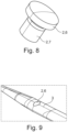
- Fig. 8 shows a perspective view of the screw 2 in a first preferred embodiment.
- the screw head 6 of the screw 2 or its surface is convexly curved.
- the screw head 6 can be essentially rotationally symmetrical, for example spherical.
- the screw head 6 has no positive engagement surfaces in this embodiment.
- Fig. 9 shows a perspective view of the instrument 3 with the screw 2 screwed into it in the first preferred embodiment. Due to the convex curvature and the circular design of the screw head 6, no gaps or pockets are formed in which dirt, tissue residues or liquids could collect.
- Fig. 10 to 12 show perspective views of the screwing tool 1.
- the screwing tool 1 can additionally have a pressure force device 10.
- the pressure force device 10 is provided and designed to adjust, calculate and/or measure the pressure force (from the second tool shaft 5 axially in the direction of the first tool shaft 4 onto the screw 2 or from the first tool shaft 4 axially in the direction of the second tool shaft 5 onto the screw 2).
- the pressure force device 10 is provided and designed to to set, calculate and/or measure an axial clamping force of the screwing tool 1 acting on the screw 2.
- the pressure force device 10 is designed such that an axial distance between the first tool shaft 4 and the second tool shaft 5 can be changed/adjusted, for example by means of a screw drive.
- the axial clamping force/axial pressure force can thus be determined depending on the length of the screw 2 to be clamped in the screwing tool 1.
- the pressure force device 10 can preferably have a tension spring 11, against the restoring force of which the axial distance between the first tool shaft 4 and the second tool shaft 5 can be changed, in the embodiment shown reduced.
- the pressure force device 10 can be operated manually or preferably automatically.
- the screwing tool 1 can additionally have a tightening device 12.
- the tightening device 12 is intended and designed to set and/or measure an angle of rotation and/or the torque of the screw engagement section 8 of the first tool shaft 4 and/or the screw engagement section 9 of the second tool shaft 5.
- the tightening device 12 can be operated manually or preferably automatically.
- the torque transmitted by the screwing tool 1 to the screw 2 for example in the manner of a torque wrench, and/or the angle of rotation transmitted by the screwing tool 1 to the screw 2, for example in the manner of an angle meter, can be set and measured with the tightening device 12. This makes it possible to adjust how far screw 2 is screwed in, i.e. which thread of screw 2 is in thread engagement.
- the tightening device 12 has a first tightening wheel 13 which is connected in a rotationally fixed manner to the first tool shaft 4. If the screw 2 is clamped into the screwing tool 1 and the first tightening wheel 13 is rotated relative to the instrument 3, the screw 2 is screwed into the instrument 3 with the friction torque resulting from the axial pressure force.
- the tightening device 12 has a second tightening wheel 14 which is connected to the second tool shaft 5 in a rotationally fixed manner. If the screw 2 is clamped into the screwing tool 1 and the second tightening wheel 14 is rotated relative to the instrument 3, the screw 2 is screwed into the instrument 3 with the friction torque resulting from the axial pressure force.
- the two tightening wheels 13, 14 can be rotated/driven integrally with one another or can be rotated/driven separately/individually from one another. Alternatively, only one tightening wheel can be provided, so that the first tool shaft 4 is also rotated relative to the second tool shaft 5 when rotated relative to the instrument (and the second tool shaft 5 only serves as a counterholder for applying the axial pressure force).
- the screwing tool 1 can have a holder 15 to which the first tool shaft 4 and/or the second tool shaft 5 are attached.
- the holder 15 has a first receptacle 16 on which the first tool shaft 4 is rotatably mounted and a second receptacle 17 on which the second tool shaft 5 is rotatably mounted.
- An axial distance between the two receptacles 16, 17 can be adjusted via the pressure force device 10.
- the holder 15 has an axial guide 18, here in the form of two rods aligned parallel to the axis of rotation, by means of which an adjustment of the axial distance is predetermined parallel to the axis of rotation.
- a scale 19 is formed on the holder 15, which indicates a screwing in or screwing out direction (close or open) of the screwing tool 1.
- the screwing tool 1 serves to screw the screw 2 into the internal thread of the instrument 3, which has two branches 20, 21, in order to connect the two branches 20, 21 of the instrument 3 to one another in such a way that the two branches 18, 19 can be pivoted relative to one another.
- the setting depth of the screw 2 or the thread of the screw 2 can be used to adjust how large a resistance moment of the two branches 20, 21 of the instrument 3, which are connected to one another in a movable/pivotable manner, is.
- the first Branch 20 of the two branches 20, 21 has a first through hole.
- the second branch 21 of the two branches 20, 21 has a second through hole on which the internal thread is formed.
- the first through hole is smaller than a diameter of the screw head 6, so that the two branches 20, 21 can be pivotably secured to one another by the screw head 6 axially resting on the first through hole and the screw shaft 7 passing through the first through hole and engaging in the internal thread in the second through hole.
- the present disclosure also relates to an assembly method for screwing the screw 2 into the internal thread of the instrument 3 having the two branches 20, 21 in order to connect the two branches 20, 21 of the instrument 3 to one another in such a way that they can be pivoted relative to one another.
- the first tool shaft 4 and the second tool shaft 5 are moved axially towards one another in order to clamp the screw 2 between its screw head 6 and its screw shaft 7 in the screwing tool 1 in such a way that a compressive force is transmitted axially from the second tool shaft 5 in the direction of the first tool shaft 4 to the screw 2 (and from the first tool shaft 4 in the direction of the second tool shaft to the screw 2).
- the screw engagement section 8 of the first tool shaft 4 is preferably moved in such a way that it bears against the screw head over an entire screw head surface.
- the screw engagement portion 9 of the second tool shaft 5 is preferably moved such that it rests against the screw shaft 7 over an entire (axial) surface thereof.
- the screwing tool 1 in particular the first tool shaft 4 and preferably the second tool shaft 5, is rotated relative to the instrument 3 about a screw longitudinal axis of the screw 2 in order to transmit a torque, in particular for setting a tightening torque or a screwing depth of the screw 2, to the screw 2 clamped in the screwing tool 1 and to screw the screw 2 into the internal thread.
- a torque in particular for setting a tightening torque or a screwing depth of the screw 2
- the screw 2 is clamped between the two screw engagement sections 8, 9, the torque can be transmitted via the screw engagement section 8 of the first tool shaft 4 is transferred to the screw 2 in a frictional manner by rotating the screw engagement section 8 of the first tool shaft 4 about the screw's longitudinal axis to generate a frictional moment.
- the screw engagement section 9 of the second tool shaft 5 can rotate/also be rotated to increase the frictional moment or can remain stationary (relative to the instrument 3) to purely apply the axial (counter) pressure force.
- the screwing tool 1 is moved in a spiral manner to screw in the screw 2.
- the screw 2 is preferably screwed into the instrument 3 until the edge of the surface of the screw head 6 and/or the screw shaft 7, depending on the instrument surface, is preferably completely but at least partially flush with a surface of the instrument 3.
- first tool shaft 4 and the second tool shaft 5 are moved axially apart in order to release the screw 2 from the screwing tool 1.
- the second tool shaft 5 can be moved towards the first tool shaft 4 and guided through the second through hole (in the second branch 21 having the internal thread) before the screw 2 is clamped into the screwing tool 1 and inserted into the internal thread.
- the second tool shaft 5 is therefore first guided through the instrument 3 ("from below", i.e. an end of the instrument 3 opposite the screw head 6) before the screw 2 is clamped in the screwing tool 1, then inserted into the internal thread in the clamped state and screwed into the internal thread by torque transmission.
- the second through hole is larger than the second tool shaft 5 so that the second tool shaft can be guided through the second through hole from below to tighten the screw 2.
- the screw can first be passed through the first through hole in the first branch 20 and inserted into the internal thread in the second branch 21 before the second tool shank 5 is passed through the second through the through hole towards the first tool shaft 4 and the screw 2 is clamped into the screwing tool 1.
- the screw 2 is first inserted "from above", ie from an end of the instrument 3 close to the screw head 6 into the internal thread, before the first tool shaft 4 and the second tool shaft 5 are moved towards each other in order to clamp the screw 2.
- the second through hole is larger than the second tool shaft 5 so that the second tool shaft can be guided from below through the second through hole to tighten the screw 2.
- the screw 2 can preferably be rotated around the screw's longitudinal direction, ie for example it can be screwed in manually a little/a few turns before the screw 2 is clamped.
- the screw 2 can be secured in its screwed-in position by laser welding and/or by adhesive applied before clamping into the screwing tool 1.
- the scope of the invention is defined by the claims.
Landscapes
- Health & Medical Sciences (AREA)
- Surgery (AREA)
- Life Sciences & Earth Sciences (AREA)
- Medical Informatics (AREA)
- Animal Behavior & Ethology (AREA)
- Engineering & Computer Science (AREA)
- Biomedical Technology (AREA)
- Heart & Thoracic Surgery (AREA)
- Ophthalmology & Optometry (AREA)
- Molecular Biology (AREA)
- Nuclear Medicine, Radiotherapy & Molecular Imaging (AREA)
- General Health & Medical Sciences (AREA)
- Public Health (AREA)
- Veterinary Medicine (AREA)
- Details Of Spanners, Wrenches, And Screw Drivers And Accessories (AREA)
- Scissors And Nippers (AREA)
- Laser Beam Processing (AREA)
- Surgical Instruments (AREA)
Claims (11)
- Outil de vissage (1) destiné à visser une vis (2), en particulier dans un filetage intérieur d'un instrument médical (3), avec- une première tige d'outil (4) qui présente de préférence un grand diamètre de tige et qui présente une section d'engagement de vis (8) du côté de l'extrémité, qui est prévue et configurée pour transmettre un couple de rotation à la vis (2),- une seconde tige d'outil (5) qui présente de préférence un petit diamètre de tige et qui peut être orientée ou est orientée axialement par rapport à la première tige d'outil (4) ainsi qu'en sens inverse de celle-ci, de telle sorte que sa section d'engagement de vis (9) du côté de l'extrémité est axialement opposée à la section d'engagement de vis (8) du côté de l'extrémité de la première tige d'outil (4) et est prévue et configurée pour transmettre à la vis (2) une force de pression axialement en direction de la première tige d'outil (4), et- une vis qui est prévue et configurée pour recevoir de la partie d'engagement de vis (8) de la première tige d'outil (4) le couple de rotation et la force de compression de la partie d'engagement de vis (9) de la seconde tige d'outil (5) et caractérisé en ce que la vis présente une tête de vis sensiblement sphérique ou tronconique.
- Outil de vissage (1) selon la revendication 1, caractérisé en ce que la section d'engagement de vis (8, 9) de la première tige d'outil (4) et/ou de la seconde tige d'outil (5) présente une surface incurvée concave, en particulier sensiblement sphérique ou tronconique.
- Outil de vissage (1) selon la revendication 1 ou 2, caractérisé par un dispositif de serrage (12) qui est prévu et configuré pour régler et/ou mesurer un angle de rotation et/ou le couple de rotation de la section d'engagement de vis (8, 9) de la première tige d'outil (4) et/ou de la seconde tige d'outil (5).
- Outil de vissage (1) selon l'une quelconque des revendications 1 à 3, caractérisé par un dispositif de force de compression (10) qui est prévu et configuré pour régler, calculer et/ou mesurer la force de compression.
- Outil de vissage (1) selon l'une quelconque des revendications 1 à 4, caractérisé en ce que la première tige d'outil (4) et la seconde tige d'outil (5) sont montées mobiles axialement l'une par rapport à l'autre, par exemple de manière pivotante ou déplaçable axialement.
- Outil de vissage (1) selon l'une quelconque des revendications 1 à 5, caractérisé en ce que la partie d'engagement de vis (8) de la première tige d'outil (4) est précontrainte par ressort dans la direction axiale vers la seconde tige d'outil (5) et/ou la partie d'engagement de vis (9) de la seconde tige d'outil (5) est précontrainte par ressort dans la direction axiale vers la première tige d'outil (4).
- Outil de vissage (1) selon l'une quelconque des revendications 1 à 6, caractérisé en ce que la première tige d'outil (4) est reliée à la seconde tige d'outil (5) de manière intégrale et couplée en rotation autour de son axe longitudinal.
- Outil de vissage (1) selon l'une quelconque des revendications 1 à 6, caractérisé en ce que la première tige d'outil (4) peut tourner relativement par rapport à la seconde tige d'outil (5) autour de son axe longitudinal.
- Procédé de montage pour visser une vis (2) dans un filetage interne d'un instrument médical (3), avec un outil de vissage (1), selon l'une quelconque des revendications 1 à 8, pour relier deux branches (20, 21) de l'instrument (3) de telle sorte que les deux branches (20, 21) puissent pivoter l'une par rapport à l'autre, caractérisé par les étapes suivantes :- le rapprochement axial d'une première tige d'outil (4) et d'une seconde tige d'outil (5) de l'outil de vissage (1) l'une vers l'autre pour serrer la vis (2) entre sa tête de vis (6) et sa tige de vis (7) dans l'outil de vissage (1), de sorte qu'une force de compression soit transmise axialement à la vis (2) de la seconde tige d'outil (5) en direction de la première tige d'outil (4),- la rotation de l'outil de vissage (1), en particulier de la première tige d'outil (4), par rapport à l'instrument (3) autour d'un axe longitudinal de vis, afin de transmettre à la vis (2) serrée dans l'outil de vissage (1) un couple de rotation, en particulier pour régler un couple de serrage ou une profondeur de vissage de la vis (2), et de visser la vis (2) dans le filetage intérieur, et- l'écartement axial de la première tige d'outil (4) et de la seconde tige d'outil (5) pour desserrer la vis (2) de l'outil de vissage (1).
- Procédé de montage selon la revendication 9, dans lequel une première branche (20) des deux branches (20, 21) présente un premier trou traversant et une seconde branche (21) des deux branches (20, 21) présente un second trou traversant au niveau duquel est formé le filetage interne, caractérisé par l'étape suivante :- le déplacement axial de la seconde tige d'outil (5) vers la première tige d'outil (4) et à travers le second trou traversant, avant que la vis (2) soit serrée dans l'outil de vissage (1) et insérée dans le filetage intérieur, ou- le passage de la vis (2) à travers le premier trou traversant et l'insertion de la vis (2) dans le filetage intérieur, avant que la seconde tige d'outil (5) soit déplacée axialement vers la première tige d'outil (4) à travers le second trou traversant et que la vis (2) soit serrée dans l'outil de vissage (1).
- Procédé de montage selon la revendication 9 ou 10, dans lequel la vis (2) est bloquée dans sa position vissée par soudage au laser et/ou par de la colle appliquée avant le serrage dans l'outil de vissage (1).
Applications Claiming Priority (2)
| Application Number | Priority Date | Filing Date | Title |
|---|---|---|---|
| DE102021108716.3A DE102021108716A1 (de) | 2021-04-08 | 2021-04-08 | Schraubwerkzeug sowie Montageverfahren mit Schraubwerkzeug |
| PCT/EP2022/059087 WO2022218770A1 (fr) | 2021-04-08 | 2022-04-06 | Outil de vissage et procédé d'assemblage utilisant un outil de vissage |
Publications (3)
| Publication Number | Publication Date |
|---|---|
| EP4319661A1 EP4319661A1 (fr) | 2024-02-14 |
| EP4319661B1 true EP4319661B1 (fr) | 2024-12-25 |
| EP4319661C0 EP4319661C0 (fr) | 2024-12-25 |
Family
ID=81328218
Family Applications (1)
| Application Number | Title | Priority Date | Filing Date |
|---|---|---|---|
| EP22717206.1A Active EP4319661B1 (fr) | 2021-04-08 | 2022-04-06 | Outil de vissage et procédé d'assemblage utilisant un outil de vissage |
Country Status (9)
| Country | Link |
|---|---|
| US (1) | US12521135B2 (fr) |
| EP (1) | EP4319661B1 (fr) |
| JP (1) | JP7728883B2 (fr) |
| CN (1) | CN117157023A (fr) |
| DE (1) | DE102021108716A1 (fr) |
| ES (1) | ES3013593T3 (fr) |
| HU (1) | HUE070011T2 (fr) |
| PL (1) | PL4319661T3 (fr) |
| WO (1) | WO2022218770A1 (fr) |
Family Cites Families (4)
| Publication number | Priority date | Publication date | Assignee | Title |
|---|---|---|---|---|
| JP4447558B2 (ja) * | 2004-01-21 | 2010-04-07 | 日本電信電話株式会社 | ネジ回し装置 |
| DE202009014310U1 (de) * | 2009-10-22 | 2010-03-04 | Thomas Tontarra Grundstücksverwaltungs GmbH & Co. KG | Chirurgisches Instrument |
| DE202013010321U1 (de) | 2013-11-14 | 2014-01-15 | Innovations-Medical Gmbh | Zangenartiges medizinisches Instrument |
| US11890728B2 (en) * | 2021-05-19 | 2024-02-06 | Nextgen Aerospace Technologies, Llc | Concentrated longitudinal acoustical/ultrasonic energy fastener design and manipulation system |
-
2021
- 2021-04-08 DE DE102021108716.3A patent/DE102021108716A1/de active Pending
-
2022
- 2022-04-06 WO PCT/EP2022/059087 patent/WO2022218770A1/fr not_active Ceased
- 2022-04-06 JP JP2023561810A patent/JP7728883B2/ja active Active
- 2022-04-06 HU HUE22717206A patent/HUE070011T2/hu unknown
- 2022-04-06 EP EP22717206.1A patent/EP4319661B1/fr active Active
- 2022-04-06 US US18/554,271 patent/US12521135B2/en active Active
- 2022-04-06 PL PL22717206.1T patent/PL4319661T3/pl unknown
- 2022-04-06 ES ES22717206T patent/ES3013593T3/es active Active
- 2022-04-06 CN CN202280027218.9A patent/CN117157023A/zh active Pending
Also Published As
| Publication number | Publication date |
|---|---|
| DE102021108716A1 (de) | 2022-10-13 |
| WO2022218770A1 (fr) | 2022-10-20 |
| US12521135B2 (en) | 2026-01-13 |
| JP2024515256A (ja) | 2024-04-08 |
| EP4319661A1 (fr) | 2024-02-14 |
| CN117157023A (zh) | 2023-12-01 |
| PL4319661T3 (pl) | 2025-04-28 |
| HUE070011T2 (hu) | 2025-05-28 |
| ES3013593T3 (en) | 2025-04-14 |
| JP7728883B2 (ja) | 2025-08-25 |
| EP4319661C0 (fr) | 2024-12-25 |
| US20240188979A1 (en) | 2024-06-13 |
Similar Documents
| Publication | Publication Date | Title |
|---|---|---|
| DE102005009879B4 (de) | Vorrichtung und Verfahren zum Herstellen einer Schraubverbindung zwischen einem ersten Bauteil und mindestens einem weiteren Bauteil | |
| EP0782898B1 (fr) | Méthode de fixation d'un dispositif de serrage sur une pièce et dispositif pour mettre en oeuvre cette méthode | |
| DE3330486A1 (de) | Spannfutter fuer werkzeug-einsatzstuecke, insbesondere schraubendreherbits | |
| EP1452276A2 (fr) | Dispositif de support pour éléments de fixation | |
| DE202006018587U1 (de) | Chirurgisches Instrument zur Implantierung eines Drahtes, vorzugsweise in einen Knochen | |
| EP3515659B1 (fr) | Montage en série d'un dispositif de serrage | |
| EP4319661B1 (fr) | Outil de vissage et procédé d'assemblage utilisant un outil de vissage | |
| DE1289499B (de) | Geraet fuer das Einsetzen von Blindmuttern in einen Bauteil | |
| EP4319662B1 (fr) | Procédé d'assemblage et outil de vissage et kit de vis | |
| DE102016205658B3 (de) | Schneidwerkzeug mit einem an einem trägerkörper durch eine spannpratze lösbar befestigtem schneidkörper | |
| DE29720247U1 (de) | Spezialzange | |
| LU101679B1 (de) | Flexadapter für Schälgerät | |
| DE3802003A1 (de) | Spannfutter fuer gewindeschaefte | |
| DE102017127590B3 (de) | Einspannvorrichtung zum Einspannen eines Werkstücks und Werkbank mit einer solchen Einspannvorrichtung | |
| DE68901823T2 (de) | Vorrichtung zum setzen von befestigungselementen. | |
| DE102023131331B3 (de) | Mitnahmewerkzeug mit verstellbarer Mitnahmekontur | |
| DE102009002155A1 (de) | Verbindung zur lösbaren Befestigung eines Gesenkes oder einer Positioniereinrichtung an einer Crimpzange sowie Positioniereinrichtung und Crimpzange mit einer solchen Verbindung | |
| DE19612752C2 (de) | Selbstklemmender Spannschlüssel | |
| DE19750617B4 (de) | Spezialzange | |
| DE3501889C1 (de) | Spannfutter für rotierende Werkzeuge | |
| DE102008058947B4 (de) | Mutternschraubgerät | |
| DE102019135096A1 (de) | Schraubnuss mit geteilter Drehmomentübertragung sowie Verfahren zum Ausgleichen von Toleranzen zwischen zwei miteinander zu verbindenden Bauteilen und Verfahren zum Sichern von Gewindemuttern | |
| DE19737202C1 (de) | Werkzeug | |
| DE102018005826A1 (de) | Adapter für eine Schraubvorrichtung | |
| DE102006016672B4 (de) | Handwerkzeug zum Arretieren einer Buchse in einer Öffnung |
Legal Events
| Date | Code | Title | Description |
|---|---|---|---|
| STAA | Information on the status of an ep patent application or granted ep patent |
Free format text: STATUS: UNKNOWN |
|
| STAA | Information on the status of an ep patent application or granted ep patent |
Free format text: STATUS: THE INTERNATIONAL PUBLICATION HAS BEEN MADE |
|
| PUAI | Public reference made under article 153(3) epc to a published international application that has entered the european phase |
Free format text: ORIGINAL CODE: 0009012 |
|
| STAA | Information on the status of an ep patent application or granted ep patent |
Free format text: STATUS: REQUEST FOR EXAMINATION WAS MADE |
|
| 17P | Request for examination filed |
Effective date: 20231102 |
|
| AK | Designated contracting states |
Kind code of ref document: A1 Designated state(s): AL AT BE BG CH CY CZ DE DK EE ES FI FR GB GR HR HU IE IS IT LI LT LU LV MC MK MT NL NO PL PT RO RS SE SI SK SM TR |
|
| DAV | Request for validation of the european patent (deleted) | ||
| DAX | Request for extension of the european patent (deleted) | ||
| GRAP | Despatch of communication of intention to grant a patent |
Free format text: ORIGINAL CODE: EPIDOSNIGR1 |
|
| STAA | Information on the status of an ep patent application or granted ep patent |
Free format text: STATUS: GRANT OF PATENT IS INTENDED |
|
| INTG | Intention to grant announced |
Effective date: 20240725 |
|
| GRAS | Grant fee paid |
Free format text: ORIGINAL CODE: EPIDOSNIGR3 |
|
| GRAA | (expected) grant |
Free format text: ORIGINAL CODE: 0009210 |
|
| STAA | Information on the status of an ep patent application or granted ep patent |
Free format text: STATUS: THE PATENT HAS BEEN GRANTED |
|
| AK | Designated contracting states |
Kind code of ref document: B1 Designated state(s): AL AT BE BG CH CY CZ DE DK EE ES FI FR GB GR HR HU IE IS IT LI LT LU LV MC MK MT NL NO PL PT RO RS SE SI SK SM TR |
|
| REG | Reference to a national code |
Ref country code: GB Ref legal event code: FG4D Free format text: NOT ENGLISH |
|
| REG | Reference to a national code |
Ref country code: CH Ref legal event code: EP |
|
| REG | Reference to a national code |
Ref country code: DE Ref legal event code: R096 Ref document number: 502022002519 Country of ref document: DE |
|
| REG | Reference to a national code |
Ref country code: IE Ref legal event code: FG4D Free format text: LANGUAGE OF EP DOCUMENT: GERMAN |
|
| U01 | Request for unitary effect filed |
Effective date: 20250120 |
|
| U07 | Unitary effect registered |
Designated state(s): AT BE BG DE DK EE FI FR IT LT LU LV MT NL PT RO SE SI Effective date: 20250124 |
|
| REG | Reference to a national code |
Ref country code: ES Ref legal event code: FG2A Ref document number: 3013593 Country of ref document: ES Kind code of ref document: T3 Effective date: 20250414 |
|
| PG25 | Lapsed in a contracting state [announced via postgrant information from national office to epo] |
Ref country code: NO Free format text: LAPSE BECAUSE OF FAILURE TO SUBMIT A TRANSLATION OF THE DESCRIPTION OR TO PAY THE FEE WITHIN THE PRESCRIBED TIME-LIMIT Effective date: 20250325 |
|
| PG25 | Lapsed in a contracting state [announced via postgrant information from national office to epo] |
Ref country code: GR Free format text: LAPSE BECAUSE OF FAILURE TO SUBMIT A TRANSLATION OF THE DESCRIPTION OR TO PAY THE FEE WITHIN THE PRESCRIBED TIME-LIMIT Effective date: 20250326 |
|
| PG25 | Lapsed in a contracting state [announced via postgrant information from national office to epo] |
Ref country code: RS Free format text: LAPSE BECAUSE OF FAILURE TO SUBMIT A TRANSLATION OF THE DESCRIPTION OR TO PAY THE FEE WITHIN THE PRESCRIBED TIME-LIMIT Effective date: 20250325 |
|
| REG | Reference to a national code |
Ref country code: HU Ref legal event code: AG4A Ref document number: E070011 Country of ref document: HU |
|
| U20 | Renewal fee for the european patent with unitary effect paid |
Year of fee payment: 4 Effective date: 20250424 |
|
| PG25 | Lapsed in a contracting state [announced via postgrant information from national office to epo] |
Ref country code: SM Free format text: LAPSE BECAUSE OF FAILURE TO SUBMIT A TRANSLATION OF THE DESCRIPTION OR TO PAY THE FEE WITHIN THE PRESCRIBED TIME-LIMIT Effective date: 20241225 |
|
| PGFP | Annual fee paid to national office [announced via postgrant information from national office to epo] |
Ref country code: ES Payment date: 20250519 Year of fee payment: 4 |
|
| PG25 | Lapsed in a contracting state [announced via postgrant information from national office to epo] |
Ref country code: IS Free format text: LAPSE BECAUSE OF FAILURE TO SUBMIT A TRANSLATION OF THE DESCRIPTION OR TO PAY THE FEE WITHIN THE PRESCRIBED TIME-LIMIT Effective date: 20250425 |
|
| PGFP | Annual fee paid to national office [announced via postgrant information from national office to epo] |
Ref country code: HU Payment date: 20250331 Year of fee payment: 4 |
|
| PG25 | Lapsed in a contracting state [announced via postgrant information from national office to epo] |
Ref country code: SK Free format text: LAPSE BECAUSE OF FAILURE TO SUBMIT A TRANSLATION OF THE DESCRIPTION OR TO PAY THE FEE WITHIN THE PRESCRIBED TIME-LIMIT Effective date: 20241225 |
|
| PG25 | Lapsed in a contracting state [announced via postgrant information from national office to epo] |
Ref country code: CZ Free format text: LAPSE BECAUSE OF FAILURE TO SUBMIT A TRANSLATION OF THE DESCRIPTION OR TO PAY THE FEE WITHIN THE PRESCRIBED TIME-LIMIT Effective date: 20241225 |
|
| PLBE | No opposition filed within time limit |
Free format text: ORIGINAL CODE: 0009261 |
|
| STAA | Information on the status of an ep patent application or granted ep patent |
Free format text: STATUS: NO OPPOSITION FILED WITHIN TIME LIMIT |
|
| REG | Reference to a national code |
Ref country code: CH Ref legal event code: L10 Free format text: ST27 STATUS EVENT CODE: U-0-0-L10-L00 (AS PROVIDED BY THE NATIONAL OFFICE) Effective date: 20251105 |
|
| REG | Reference to a national code |
Ref country code: CH Ref legal event code: H13 Free format text: ST27 STATUS EVENT CODE: U-0-0-H10-H13 (AS PROVIDED BY THE NATIONAL OFFICE) Effective date: 20251125 |
|
| 26N | No opposition filed |
Effective date: 20250926 |
|
| PG25 | Lapsed in a contracting state [announced via postgrant information from national office to epo] |
Ref country code: MC Free format text: LAPSE BECAUSE OF FAILURE TO SUBMIT A TRANSLATION OF THE DESCRIPTION OR TO PAY THE FEE WITHIN THE PRESCRIBED TIME-LIMIT Effective date: 20241225 |
|
| PG25 | Lapsed in a contracting state [announced via postgrant information from national office to epo] |
Ref country code: CH Free format text: LAPSE BECAUSE OF NON-PAYMENT OF DUE FEES Effective date: 20250430 |
|
| PGFP | Annual fee paid to national office [announced via postgrant information from national office to epo] |
Ref country code: GB Payment date: 20260324 Year of fee payment: 5 |
|
| PG25 | Lapsed in a contracting state [announced via postgrant information from national office to epo] |
Ref country code: IE Free format text: LAPSE BECAUSE OF NON-PAYMENT OF DUE FEES Effective date: 20250406 |
|
| PG25 | Lapsed in a contracting state [announced via postgrant information from national office to epo] |
Ref country code: HR Free format text: LAPSE BECAUSE OF FAILURE TO SUBMIT A TRANSLATION OF THE DESCRIPTION OR TO PAY THE FEE WITHIN THE PRESCRIBED TIME-LIMIT Effective date: 20241225 |
|
| PGFP | Annual fee paid to national office [announced via postgrant information from national office to epo] |
Ref country code: PL Payment date: 20260330 Year of fee payment: 5 |