EP4320499B1 - Système et procédé de suivi du regard utilisant des reflets sélectifs - Google Patents
Système et procédé de suivi du regard utilisant des reflets sélectifs Download PDFInfo
- Publication number
- EP4320499B1 EP4320499B1 EP22715651.0A EP22715651A EP4320499B1 EP 4320499 B1 EP4320499 B1 EP 4320499B1 EP 22715651 A EP22715651 A EP 22715651A EP 4320499 B1 EP4320499 B1 EP 4320499B1
- Authority
- EP
- European Patent Office
- Prior art keywords
- illuminator
- user
- eye
- illuminators
- given
- Prior art date
- Legal status (The legal status is an assumption and is not a legal conclusion. Google has not performed a legal analysis and makes no representation as to the accuracy of the status listed.)
- Active
Links
Images


Classifications
-
- G—PHYSICS
- G06—COMPUTING OR CALCULATING; COUNTING
- G06T—IMAGE DATA PROCESSING OR GENERATION, IN GENERAL
- G06T7/00—Image analysis
- G06T7/70—Determining position or orientation of objects or cameras
- G06T7/73—Determining position or orientation of objects or cameras using feature-based methods
-
- G—PHYSICS
- G02—OPTICS
- G02B—OPTICAL ELEMENTS, SYSTEMS OR APPARATUS
- G02B27/00—Optical systems or apparatus not provided for by any of the groups G02B1/00 - G02B26/00, G02B30/00
- G02B27/0093—Optical systems or apparatus not provided for by any of the groups G02B1/00 - G02B26/00, G02B30/00 with means for monitoring data relating to the user, e.g. head-tracking, eye-tracking
-
- G—PHYSICS
- G02—OPTICS
- G02B—OPTICAL ELEMENTS, SYSTEMS OR APPARATUS
- G02B27/00—Optical systems or apparatus not provided for by any of the groups G02B1/00 - G02B26/00, G02B30/00
- G02B27/01—Head-up displays
- G02B27/017—Head mounted
-
- G—PHYSICS
- G06—COMPUTING OR CALCULATING; COUNTING
- G06F—ELECTRIC DIGITAL DATA PROCESSING
- G06F3/00—Input arrangements for transferring data to be processed into a form capable of being handled by the computer; Output arrangements for transferring data from processing unit to output unit, e.g. interface arrangements
- G06F3/01—Input arrangements or combined input and output arrangements for interaction between user and computer
- G06F3/011—Arrangements for interaction with the human body, e.g. for user immersion in virtual reality
- G06F3/013—Eye tracking input arrangements
-
- G—PHYSICS
- G06—COMPUTING OR CALCULATING; COUNTING
- G06V—IMAGE OR VIDEO RECOGNITION OR UNDERSTANDING
- G06V10/00—Arrangements for image or video recognition or understanding
- G06V10/10—Image acquisition
- G06V10/12—Details of acquisition arrangements; Constructional details thereof
- G06V10/14—Optical characteristics of the device performing the acquisition or on the illumination arrangements
- G06V10/141—Control of illumination
-
- G—PHYSICS
- G06—COMPUTING OR CALCULATING; COUNTING
- G06V—IMAGE OR VIDEO RECOGNITION OR UNDERSTANDING
- G06V40/00—Recognition of biometric, human-related or animal-related patterns in image or video data
- G06V40/10—Human or animal bodies, e.g. vehicle occupants or pedestrians; Body parts, e.g. hands
- G06V40/18—Eye characteristics, e.g. of the iris
- G06V40/19—Sensors therefor
-
- G—PHYSICS
- G06—COMPUTING OR CALCULATING; COUNTING
- G06T—IMAGE DATA PROCESSING OR GENERATION, IN GENERAL
- G06T2207/00—Indexing scheme for image analysis or image enhancement
- G06T2207/30—Subject of image; Context of image processing
- G06T2207/30196—Human being; Person
- G06T2207/30201—Face
Definitions
- the present disclosure relates to gaze-tracking systems for use in head-mounted display apparatuses, said gaze-tracking systems employing selective glints. Moreover, the present disclosure relates to gaze-tracking methods employing selective glints. Furthermore, the present disclosure relates to display apparatuses incorporating said gaze-tracking systems.
- immersive technologies such as virtual-reality, augmented-reality, mixed-reality (collectively referred to as extended-reality (XR) technology) are being employed in various fields such as entertainment, real-estate, combat training, medical imaging operations, simulators, navigation, and the like.
- these immersive technologies are employed in display apparatuses to provide immersive XR environments to a user.
- the display apparatus may include a head-mounted device (HMD) at which images corresponding to the XR environment are displayed.
- HMD head-mounted device
- the user generally wears (namely, supports) the HMD on his/her head.
- the HMD employs a gaze-tracking (namely, eye tracking) system to detect a gaze direction of the user.
- a gaze-tracking system determines a position of pupils of the user's eyes, and subsequently monitors change in the position of the pupils.
- several illuminators are employed for emitting light towards the user's eyes, and a camera is employed for capturing an image depicting the user's eyes and reflections of the emitted light from the user's eyes. Thereafter, the reflections of the emitted light are used as reference for determining the position of the pupils and the gaze direction of the user.
- gaze-tracking systems are associated with several limitations. These gaze-tracking systems are generic in nature and are not optimized on a per-user basis. Firstly, while using the HMD, a portion of trackable features of the user's eyes are often obscured or occluded by reflections and glares from eyeglasses of the user, eyelids of the user (for example, when the user blinks or squints his/her eyes), eyelashes of the user, epicanthic folds of the user's eyes, and the like. In such an instance, some of the reflections are absent in the captured images of the user's eyes since some emitted light from illuminators is not reflected by an ocular surface of the user's eyes.
- the existing gaze-tracking systems often misinterpret visual artifacts (for example, reflections or glares of light emitted by displays or projectors of the HMD, false reflections of light from the eyeglasses of the user, false reflections of light from the ocular surface of the user's eyes, and the like) to be the reflections of the light emitted by the illuminators.
- the gaze-tracking systems utilize such erroneous visual artifacts and determine an inaccurate gaze direction of the user.
- said visual artifacts are introduced due to an off-axis placement of the camera as well as due to some manufacturing anomalies in mechanics and/or in optics of the HMD.
- Patent application US20190324272A1 (Wontaek Seo et al. ; "3-dimensional image display apparatus and method of providing expanded viewing window”) describes an apparatus and method of providing an expanded viewing window wherein the apparatus comprises an eye tracking sensor.
- the apparatus and the method are generic and not optimized for a per-user basis.
- Patent application US20190138094A1 discloses a gaze-tracking system for use in a head-mounted display apparatus and a method of tracking a user's gaze.
- the gaze-tracking system utilizes the plurality of non-circular light sources for emitting light to illuminate the user's eye solving the problem of inaccurate gaze detection due to occlusion of the user's eyes and presence of visual artifacts in an image of the user's eyes.
- patent application WO2019185136A1 (Tobii AB ; "Method and system for controlling illuminators”) there is a method for controlling illuminators in an eye tracking system and a corresponding system.
- the system includes a plurality of illuminators arranged such that each illuminator of the illuminators is located at a respective fixed position in relation to an eye of a user when using the system.
- the method comprises illuminating the eye of the user by means of the plurality of illuminators, and receiving an image of the eye of the user from an image sensor, the image resulting from the image sensor detecting light from the plurality of illuminators reflected from the eye of the user and reflected from an optic arrangement located between the plurality of illuminators and the eye of the user.
- mapping glints to light sources discloses a technology that provides various ways for mapping glints that reflect off from an object to light sources responsible for the glints and that ables to correctly map glints to light sources by capturing just a few images with a camera. Each image is captured while illuminating the object with a different pattern of light sources. A glint free image may also be determined.
- a head-worn display including a display panel sized and positioned to produce a field of view to present digital content to an eye of a user, and a processor adapted to present the digital content to the display panel such that the digital content is only presented in a portion of the field of view, the portion being in the middle of the field of view such that horizontally opposing edges of the field of view are blank areas is disclosed.
- the processor is adapted to shift the digital content into one of the blank areas to adjust the convergence distance of the digital content and thereby change the perceived distance from the user to the digital content.
- the patent application WO2019067731A1 discloses devices, systems, and methods for determining an eye tracking characteristic using intensity-modulated light sources.
- the method includes emitting light with modulating intensity from a plurality of light sources towards an eye of a user and receiving light intensity data indicative of an intensity of the emitted light reflected by the eye of the user in the form of a plurality of glints to determine an eye tracking characteristic of the user based on the light intensity data. It is also diclosed that the method includes an event camera comprising a plurality of light sensors at a plurality of respective locations.
- the present disclosure seeks to provide a gaze-tracking system for use in a head-mounted display apparatus, said gaze-tracking system employing selective glints.
- the present disclosure also seeks to provide a gaze-tracking method employing selective glints.
- the present disclosure also seeks to provide a display apparatus incorporating said gaze-tracking system.
- an embodiment of the present disclosure provides a gaze-tracking system for use in a head-mounted display apparatus, the gaze-tracking system comprising:
- an embodiment of the present disclosure provides a gaze-tracking method comprising:
- an embodiment of the present disclosure provides a display apparatus comprising:
- Embodiments of the present disclosure substantially eliminate or at least partially address the aforementioned problems in the prior art, and enable accurate and reliable detection of gaze direction of the user by way of optimizing the gaze-tracking system on a user-specific basis. Additional aspects, advantages, features and objects of the present disclosure would be made apparent from the drawings and the detailed description of the illustrative embodiments construed in conjunction with the appended claims that follow.
- an underlined number is employed to represent an item over which the underlined number is positioned or an item to which the underlined number is adjacent.
- a non-underlined number relates to an item identified by a line linking the non-underlined number to the item. When a number is non-underlined and accompanied by an associated arrow, the non-underlined number is used to identify a general item at which the arrow is pointing.
- an embodiment of the present disclosure provides a gaze-tracking system for use in a head-mounted display apparatus, the gaze-tracking system comprising:
- an embodiment of the present disclosure provides a gaze-tracking method comprising:
- an embodiment of the present disclosure provides a display apparatus comprising:
- the present disclosure provides the aforementioned gaze-tracking system, the aforementioned gaze-tracking method, and the aforementioned display apparatus.
- the gaze-tracking system utilizes at least one illuminator for emitting light to illuminate the user's eye.
- the reflections of the at least one illuminator in the eye image are utilized to accurately detect the gaze direction of the user.
- Said at least one illuminator is selected from amongst the plurality of illuminators, based on the user-specific scores computed for the plurality of illuminators.
- the (user-specific optimized) gaze-tracking system mitigates visual artifacts in the captured eye images by using selective illuminator(s) for illumination during gaze tracking, to detect a highly accurate gaze direction of the user.
- power consumption and thermal impact associated with use of the head-mounted display apparatus is minimal, thus facilitates in saving costs and energy.
- the gaze-tracking system can be utilized for accurately determining the gaze direction of the user even when the user's eye is partially occluded by its own features or by eyeglasses, and even without knowledge of eyeglass optics and other user-specific traits.
- the gaze-tracking system can be easily used in various types of head-mounted display apparatuses without obstructing the user's view.
- the gaze-tracking method is fast, reliable and can be implemented with ease.
- the term "gaze-tracking system” refers to specialized equipment for tracking a gaze direction of the user.
- the gaze-tracking system detects and/or follows gaze of the user.
- the head-mounted display apparatus uses the gaze-tracking system for tracking the gaze direction of the user via non-invasive techniques.
- the gaze-tracking system is arranged (in the head-mounted display apparatus) in a manner that it does not cause any obstruction in the user's view.
- an accurate tracking of the gaze direction facilitates the head-mounted display apparatus to closely implement gaze contingency when presenting an extended-reality (XR) environment to the user.
- XR extended-reality
- the gaze-tracking system may also be referred to as an "eye-tracker system", a "means for detecting a gaze direction", a "means for tracking a gaze direction", or a "gaze-tracking unit”.
- the term “head-mounted display apparatus” refers to specialized equipment that is configured to present the XR environment to the user when said display apparatus in operation is worn by the user on his/her head.
- the head-mounted display apparatus is implemented, for example, as an XR headset, a pair of XR glasses, and the like, that is operable to display a visual scene of the XR environment to the user.
- the head-mounted display apparatus may also simply be referred to as “display apparatus” as it is head-mounted only in use.
- extended-reality encompasses virtual reality (VR), augmented reality (AR), mixed reality (MR), and the like.
- the at least one processor is coupled to various components of the gaze-tracking system, and is configured to control the operation of the gaze-tracking system.
- the at least one processor of the gaze-tracking system is implemented by way of at least one processor of the head-mounted display apparatus.
- the gaze-tracking system and the head-mounted display apparatus have separate processors.
- the term "illuminator” refers to equipment that, in operation, emits light.
- a given illuminator include, but are not limited to, a light-emitting diode, a projector, a display, a laser.
- the plurality of illuminators emit light of an infrared wavelength or a near-infrared wavelength.
- the emitted light of the infrared wavelength or the near-infrared wavelength is invisible (or imperceptible) to the human eye, thereby, reducing unwanted distraction when such light is incident upon the user's eye.
- the plurality of illuminators emit light of a visible wavelength.
- the plurality of illuminators are implemented by way of at least two of: infrared light-emitting diodes, infrared lasers, infrared light projectors, infrared light-emitting diode based displays, visible light-emitting diodes, visible light lasers, visible light projectors.
- the at least one processor is configured to control the plurality of illuminators to emit light (namely, be illuminated) in the sequential manner.
- a given illuminator may be switched on to be illuminated, using a control signal, by the at least one processor.
- the sequential manner of illumination may be repeated as required.
- the plurality of illuminators may comprise 10 illuminators that are to be illuminated in the sequential manner, wherein a first illuminator is illuminated at an instant of time t1, a second illuminator is illuminated at an instant of time t2, a third illuminator is illuminated at an instant of time t3, and so on.
- the term "camera” refers to equipment that is operable to detect and process the light reflected from the user's eye, so as to capture the plurality of eye images of the user's eye and reflections of the plurality of illuminators (during the illumination of the respective illuminators) from the user's eye.
- the at least one camera may capture 10 eye images of the user's eye during illumination of 10 illuminators, wherein one illuminator is illuminated at a given instant of time and one eye image is captured corresponding to the given instant of time.
- the at least one processor is configured to: control the at least one camera to capture test images, and process the captured test images to detect whether or not the user's eye is in proximity of the head-mounted display apparatus.
- features such as edges, corners, curves, reflections, blobs, ridges, and the like
- the at least one processor is configured to: control the at least one camera to capture test images, and process the captured test images to detect whether or not the user's eye is in proximity of the head-mounted display apparatus.
- features such as edges, corners, curves, reflections, blobs, ridges, and the like
- the at least one processor When processing the captured test images, the at least one processor optionally employs at least one feature extraction algorithm (such as an edge-detection algorithm, a corner-detection algorithm, a blob-detection algorithm, a feature detector algorithm, and the like).
- at least one feature extraction algorithm such as an edge-detection algorithm, a corner-detection algorithm, a blob-detection algorithm, a feature detector algorithm, and the like.
- feature extraction algorithms are well known in the art.
- the at least one processor is configured to perform detection of the proximity between the user's eye and the head-mounted display apparatus by utilizing a depth camera.
- the at least one processor is configured to control the depth camera to capture at least one depth image of the user's eye.
- the at least one processor is configured to process the at least one depth image for generating a depth map, wherein the depth map comprises information pertaining to the optical depth of the user's eye with respect to the head-mounted display apparatus.
- the at least one depth image is a two-dimensional image or a three-dimensional image.
- the depth camera examples include, but are not limited to, a Red-Green-Blue-Depth (RGB-D) camera, a ranging camera, a Light Detection and Ranging (LiDAR) camera, a flash LiDAR camera, a Time-of-Flight (ToF) camera, a Sound Navigation and Ranging (SONAR) camera, a laser rangefinder, a stereo camera, a plenoptic camera, an infrared camera, a structured-light scanner, and an ultrasound imaging equipment.
- the depth camera may be implemented as a camera of the head-mounted display apparatus.
- the features of the user's eye are utilized by the at least one processor to estimate an inter-pupillary distance (IPD) of the user, when an arrangement of the user's eye with respect to the head-mounted display apparatus stabilizes.
- IPD inter-pupillary distance
- the user wears the head-mounted display apparatus he/she generally keeps adjusting the head-mounted display apparatus on his/her head until a comfortable fit of the head-mounted display apparatus on the head is achieved.
- the comfortable fit is achieved, the arrangement of the user's eye with respect to the head-mounted display apparatus stabilizes.
- an average IPD of humans is not constant, and substantially varies from person to person.
- the IPD of a given user substantially changes with physical development (namely, growth) of the given user.
- an IPD of a child is substantially different from that of an adult.
- the average IPD also varies substantially among users in a same age group. For example, a middle-aged woman may have a lesser average IPD as compared to a middle aged-man.
- the IPD of the given user varies substantially with whether the given user is focusing at nearby objects or far-away objects within a real-world scene. IPD estimation facilitates in presenting user-specific optimized images to the user of the head-mounted display apparatus.
- the sequential illumination of the plurality of illuminators and capturing of the plurality of eye images are repeated as long as the user's eye does not appear to be stabilized with respect to the head-mounted display apparatus.
- the at least one processor is configured to compare corresponding features of the user's eye in the plurality of eye images captured in a complete duration of a sweep of the sequential illumination of the plurality of illuminators. When there is nil or minimal change in position and/or orientation of the corresponding features of the user's eye (in the plurality of eye images) for the complete duration of said sweep, the user's eye is determined to be stabilized with respect to the head-mounted display apparatus.
- the at least processor is configured to employ at least one image processing algorithm to identify the at least one reflection of the given illuminator that is visible in the corresponding eye image.
- the at least one image processing algorithm is at least one of: a local thresholding algorithm to detect shapes that are brighter than their immediate neighbourhood, a de-noising algorithm to remove noise in the corresponding eye image, a shape recognition algorithm, a pattern recognition algorithm.
- Other suitable image processing algorithms are also feasible to be employed by the at least one processor.
- the at least one reflection of the given illuminator is from an ocular surface of the user's eye, a surface of eyeglasses worn by the user, a surface of contact lenses worn by the user, and the like.
- Reflection(s) of the given illuminator that have a shape, a position, and a rotational orientation corresponding to the given illuminator are formed as glints, which are required to be identified accurately for accurate gaze-tracking.
- some visual artifacts (such as glares caused by the given illuminator) may be formed as false reflections which may be a part of the at least one reflection of the given illuminator, in the corresponding eye image.
- visual artifacts are undesirable visual anomalies or visual imposters (obscuring trackable features of the user's eye) that are formed as the false reflections and are represented as the glares.
- the visual artifacts may also be caused by user's features (namely, traits) such as long eye lashes of the user, epicanthic folds of the user's eye, and the like, or by manufacturing inaccuracies in mechanics and/or optics of the head-mounted display apparatus.
- the processor is optionally configured to employ at least one data processing algorithm to map the at least one reflection that is visible in the corresponding eye image with a known shape of the given illuminator, to identify and discard the visual artifacts.
- the at least one data processing algorithm matches the known shape of the given illuminator with all reflections that are visible in the corresponding eye image, identifies as visual artifacts those reflections which do not match with the known shape of the given illuminator, and discards such identified visual artifacts.
- the identification and discarding of the visual artifacts may optionally also be done using a known position, and a known rotational orientation corresponding to the given illuminator.
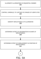
- the extent of deformation in the shape of the at least one reflection with respect to the shape of the given illuminator is determined to detect whether or not the shape of the at least one reflection of the given illuminator is consistent with the shape of the given illuminator. Lesser the extent of deformation, greater is the consistency between the shape of the at least one reflection and the shape of the given illuminator, and vice versa. In other words, a low extent of deformation indicates that the shape of the at least one reflection is highly similar to an expected shape for the at least one reflection corresponding to the shape of the given illuminator.
- the low extent of deformation is indicative of low distortion (for example, minimal bending, minimal buckling, minimal twisting, and the like) in the shape of the at least one reflection.
- the extent of deformation is measured in units of length, wherein the units of length are micrometres or millimetres.
- the extent of deformation is measured in pixel units (i.e., a number of pixels).
- the extent of displacement in the position of the at least one reflection relative to the user's eye with respect to the position of the given illuminator relative to the user's eye is determined to detect whether or not the position of the at least one reflection is consistent with the position of the given illuminator. Lesser the extent of displacement, greater is the consistency between the position of the at least one reflection and the position of the given illuminator, relative to the user's eye, and vice versa. In other words, a low extent of displacement indicates that the position of the at least one reflection is highly close to an expected position of the at least one reflection corresponding to the position of the given illuminator relative to the user's eye.
- the extent of displacement is measured in units of length, wherein the units of length are micrometres or millimetres.
- the extent of displacement is measured in pixel units (i.e., a number of pixels).
- the at least one processor is configured to determine an extent of occlusion of the pupil of the user's eye by the at least one reflection caused by the given illuminator, and compute the user-specific score for the given illuminator based also on the extent of occlusion.
- the extent of occlusion is determined to detect how much the at least one reflection occludes (namely, obscures) the pupil in the corresponding eye image. Lesser the extent of occlusion, lesser is the occlusion of the pupil by the at least one reflection in the corresponding eye image, and vice versa.
- the at least one reflection could include both glints as well as visual artifacts.
- a less extent of occlusion corresponds to a high visibility of the pupil in the corresponding eye image, which is desirable as the pupil is a trackable feature of the user's eye.
- the less extent of occlusion indicates that the given illuminator beneficially forms nil or less-occluding visual artifacts, that do not adversely impact tracking of the pupil.
- the extent of occlusion is measured in units of length, wherein the units of length are micrometres or millimetres.
- the extent of occlusion is measured in pixel units (i.e., a number of pixels).
- the plurality of illuminators are arranged around a periphery of an exit optical element of the head-mounted display apparatus.
- the plurality of illuminators are arranged to physically surround the exit optical element.
- exit optical element refers to an optical component that is configured to direct a projection of the visual scene towards the user's eye, when the head-mounted display apparatus, in operation, is worn by the user.
- the exit optical element is the component that is closest to the user's eye in the head-mounted display apparatus. Therefore, the term “exit optical element” may also be commonly referred to as an "eyepiece". Furthermore, optionally, the exit optical element is implemented by way of at least one of: a convex lens, a plano-convex lens, a Liquid Crystal (LC) lens, a liquid lens, a Fresnel lens, aspherical lens, achromatic lens. Other suitable examples for implementing the exit optical element are also feasible.
- LC Liquid Crystal
- the term "user-specific score" for a given illuminator refers to a score indicative of an amount of error produced by the given illuminator due to visual artifacts (such as glares, false reflections, and the like) caused by the given illuminator for a given user using the head-mounted display apparatus, during a given viewing session. Lesser the amount of error produced by the given illuminator, greater is the user-specific score for the given illuminator, and vice versa.
- the user-specific score is a function of at least the extent of deformation and the extent of displacement. Additionally, optionally, the user-specific score is a function of the extent of occlusion.
- the user-specific score for the given illuminator is directly related to a cost-benefit ratio of the given illuminator.
- the at least one processor employs at least one mathematical formula for computing the user-specific score for the given illuminator based at least on the extent of deformation and the extent of displacement.
- the user-specific score is inversely related to the extent of deformation and the extent of displacement.
- at least one mathematical formula computes the user-specific score for the given illuminator based also on the extent of occlusion, wherein the user-specific score is inversely related to the extent of occlusion.
- the at least one mathematical formula may be employed in at least one pseudocode.
- the user-specific score for the given illuminator lies in a range of 0 to 1.
- 0 indicates lowest user-specific score (or worst user-specific score), while 1 indicates highest user-specific score (or perfect user-specific score).
- the user-specific score for the given illuminator may be from 0, 0.1, 0.2, 0.3, 0.4, 0.5, 0.6, 0.7, 0.8 or 0.9 up to 0.1, 0.2, 0.3, 0.4, 0.5, 0.6, 0.7, 0.8, 0.9 or 1.
- the user-specific score for the given illuminator lies in a range of -1 to 1.
- the user-specific score for the given illuminator may be from -1, -0.9, -0.8, -0.7, -0.6, -0.5, -0.4,-0.3, -0.2, - 0.1, 0, 0.1, 0.2, 0.3, 0.4, 0.5, 0.6, 0.7, 0.8 or 0.9 up to -0.9, -0.8, -0.7, -0.6, -0.5, -0.4,-0.3, -0.2, -0.1, 0, 0.1, 0.2, 0.3, 0.4, 0.5, 0.6, 0.7, 0.8, 0.9 or 1.
- the user-specific score for the given illuminator lies in a range of 0 to 100.
- 0 indicates lowest user-specific score
- 100 indicates highest user-specific score.
- the user-specific score for the given illuminator may be from 0, 10, 20, 30, 40, 50, 60, 70, 80, or 90 up to 10, 20, 30, 40, 50, 60, 70, 80, 90 or 100.
- Other suitable ranges of the user-specific score for the given illuminator are also feasible.
- the at least one processor is configured to: sort the user-specific scores computed for the plurality of illuminators in a descending order, and select the at least one illuminator corresponding to top at least one user-specific score from amongst the sorted user-specific scores.
- said illuminator has a highest user-specific score from amongst the user-specific scores computed for the plurality of illuminators.
- a given illuminator could have fairly large dimensions as well as a shape that could overlap physically with another illuminator (such as a large cross (X) sign formed by two V-shaped illuminators). Therefore, even a single useful illuminator having a high user-specific score enables accurate gaze-tracking.
- the illuminators having top highest user-specific scores are prioritized over illuminator(s) having a low user-specific scores for said selection.
- the given illuminator having a highest user-specific score is selected as a first illuminator
- a given illuminator having a second-highest user-specific score is selected as a second illuminator
- a given illuminator having a third-highest user-specific score is selected as a third illuminator, and so on.
- the user-specific scores computed for 8 illuminators I1, I2, I3, I4, I5, I6, I7, and I8 may be 0.65, 0.25, 0.50, 0.95, 0.35, 0.82, 0.75, and 0.10, respectively.
- 4 illuminators I4, I6, I7, and I1 are selected based on top four user-specific scores (namely, 0.95, 0.82, 0.75, and 0.65).
- the selection of the at least one illuminator from amongst the plurality of illuminators is performed for the user each time that the head-mounted display apparatus is used by the user for a given viewing session. Only the at least one illuminator that is selected for the given viewing session, is utilized for an entire duration of the given viewing session.
- the selection of the at least one illuminator is performed again as removal of the head-mounted display apparatus could affect eyeglass angle or eye-position of the user.
- the selection of the at least one illuminator is also repeated when the head-mounted display apparatus has shifted (for example, due to a sudden jerk, movement of the user, and the like) on the user's head.
- the at least one processor is configured to determine a glint latency sync between the head-mounted display apparatus and a computing device (such as a computer) associated with the head-mounted display apparatus.
- a glint latency is determined in terms of a number of milliseconds elapsed from a glint control command being issued or an eye image being captured to identify the at least one reflection of the given illuminator, to the eye image being available on the computing device.
- glint latency square wave signals are not detected accurately within 50 eye images, the glint latency sync may fail.
- the at least one illuminator is selected from amongst the plurality of illuminators. Said selection may fail when the user's eye (in particular, a pupil of the user's eye) is not detected for a given duration such as for example, 200 millisecond.
- the user's IPD is optionally determined automatically. IPD determination may be skipped if this functionality is disabled (for example, by the user).
- the head-mounted display apparatus is calibrated using a crosshair jig which allows to map an optical axis of a lens of the head-mounted display apparatuses against a position in the at least one camera.
- optical sweet spot This is known as "optical sweet spot” towards which chambers are driven.
- separate chambers for a left eye and a right eye of the user are formed in the head-mounted display apparatus.
- the chambers have to be driven outwards, and vice versa, until a predefined threshold (such as 0.5 millimetres) of the IPD is attained.
- the head-mounted display apparatuses has a motor to control position of the chamber, which allows to automatically match the user's IPD.
- the at least one illuminator is selected again from amongst the plurality of illuminators.
- the at least one processor is configured to calibrate the gaze-tracking system. Such calibration of the gaze-tracking system is generally known in the art.
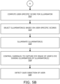
- the selected at least one illuminator is illuminated and is then employed to detect the gaze direction of the user.
- the at least one processor is configured to control the selected at least one illuminator to emit the light (or be illuminated).
- the selected at least one illuminator may be switched on to be illuminated, using a control signal, by the at least one processor.
- a single illuminator is illuminated, whereas in other implementations, more than one illuminator is illuminated.
- the more than one illuminators are illuminated simultaneously, and then are employed to detect the gaze direction of the user. Referring to the first example, the selected 4 illuminators I1, I4, I6, and I7 are illuminated simultaneously, and are employed to detect the gaze direction of the user.
- the at least one camera initially captures the plurality of eye images of the user's eye during illumination of respective illuminators with high brightness and intensity for achieving requisite visual clarity in the plurality of eye images.
- This enables in accurate detection (and discarding) of the visual artifacts.
- the at least one processor reduces an amount of current supplied to the at least one illuminator to reduce a brightness level of the at least one illuminator.
- power consumption and/or thermal impact would be minimal due to the reduced current usage.
- the power consumption and/or the thermal impact would automatically reduce when a number of illuminator(s) used for gaze tracking and required brightness levels of such illuminator(s) reduce.
- the brightness levels of the at least one illuminators decrease, the visual artifacts such as glares, false reflections, and the like, caused by such illuminators are mitigated.
- the at least processor controls the at least one camera to capture the eye image of the user's eye during illumination of the at least one illuminator.
- the eye image captured during the illumination of the at least one illuminator represents the (useful) reflections of the at least one illuminator from the ocular surface of the user's eye, the surface of eyeglasses worn by the user, the surface of contact lenses worn by the user, and the like.
- the reflections of the at least one illuminator in the eye image act as a frame of reference against which the relative position of the pupil is calculated to determine the gaze direction of the user.
- the at least one processor utilizes knowledge of geometry between the reflections of the at least one illuminator, the at least one illuminator and the at least one camera to accurately determine the relative position of the pupil of the user's eye with respect to said reflections.
- the determined relative position of the pupil with respect to said reflections enables the at least one processor to correctly discern the gaze direction of the user.
- the relative position of the pupil of the user's eye with respect to the reflections of the at least one illuminator in the eye image may be towards left of the reflections, thereby indicating that the gaze direction of the user is towards a right direction (or a right portion of the visual scene).
- the gaze direction of the user is detected continuously while the user views the images displayed via the at least one light source, and the gaze direction of the user is beneficially optionally utilized by the at least one processor during generation of the images to be displayed.
- employing the reflections of the at least one illuminator that correspond to useful glints allows for enhancing an accuracy of the detected gaze direction of the user, since this ensures that the visual artifacts are considerably mitigated and the at least one processor utilizes useful reflections (glints) of the at least one illuminator whilst detecting the gaze direction of the user. Gaze tracking using the reflections of the at least one illuminator also ensures that trackable features of the user's eye are not obscured with visual artifacts, and the gaze direction of the user can be determined accurately and time-efficiently.
- the gaze-tracking system further comprises at least one optical element that is transparent for visible light, but is reflective for infrared or near-infrared light, wherein the at least one optical element is positioned on an optical path between the at least one light source of the head-mounted display apparatus and the exit optical element, and wherein light corresponding to the reflections of the plurality of illuminators, when incident upon the at least one optical element, is reflected towards the at least one camera.
- the term "at least one optical element” refers to at least one optical component having optical properties such that the at least one optical component is transparent for visible light, but is reflective for infrared or near-infrared light.
- the at least one optical element allows the visible light emanating from the at least one light source to pass therethrough towards the exit optical element. Furthermore, the at least one optical element reflects the reflections of the plurality of illuminators from the user's eye towards the at least one camera. By adjusting the optical path of the reflections of the plurality of illuminators, the at least one optical element allows the at least one camera to capture the plurality of eye images of the user's eye even when the at least one camera is not directly arranged in front of the user's eye. As a result, the at least one camera can be compactly arranged in any suitable space within the head-mounted display apparatus, and need not necessarily face the user's eye.
- the at least one optical element also allows for reducing unwanted visible light from being captured by the at least one camera.
- the at least one optical element is implemented by way of at least one of: a semi-transparent mirror, a semi-transparent film, a prism, a polarizer, an optical waveguide.
- the term "light source” refers to an element that is to be employed to display the images to the user.
- the at least one light source is implemented as at least one display.
- a given image is displayed at the at least one display.
- the at least one display include, but are not limited to, a Liquid Crystal Display (LCD), a Light-Emitting Diode (LED)-based display, an Organic LED (OLED)-based display, a micro OLED-based display, an Active Matrix OLED (AMOLED)-based display, and a Liquid Crystal on Silicon (LCoS)-based display.
- the at least one light source is implemented as at least one projector.
- a given image is projected onto a projection screen or directly onto a retina of the user's eyes.
- the at least one projector include, but are not limited to, an LCD-based projector, an LED-based projector, an OLED-based projector, an LCoS-based projector, a Digital Light Processing (DLP)-based projector, and a laser projector.
- DLP Digital Light Processing
- the plurality of illuminators are non-circular in shape, and wherein the at least one processor is configured to:
- a given illuminator has a shape that is symmetrical about only one axis and that has rotational uniqueness about 360 degrees.
- a shape of the given illuminator is symmetrical about only one axis and such shape only repeats when said illuminator is rotated through 360 degrees.
- the at least one reflection of the plurality of illuminators is symmetrical about only one axis. In reality, the shape of the at least one reflection not only depends on the shape of its corresponding illuminator, but also on a curvature of a surface of the user's eye from where the at least one reflection occurred.
- the shape of the given illuminator is selected from a group consisting of A, V and Y.
- the shape of the given illuminator is selected from a group consisting of B, C, D, E, M, T, U and W.
- the shape of the given illuminator need not necessarily be an alphabetic character, but could also be a number or a pattern that is symmetrical about only one axis and that has rotational uniqueness about 360 degrees.
- the given illuminator may be V-shaped. In such a case, the V-shape of the given illuminator is symmetrical about only one axis, and has rotational uniqueness about 360 degrees.
- the "rotational orientation" of the given illuminator that is V-shaped refers to a direction where a tip of the V shape of the given illuminator is pointing, and a position of the given illuminator refers to an angle [0, 360] where the given non-circular light source is positioned on a circular rim of the exit optical elements, as measured from a centre of said circular rim.
- the gaze-tracking system may comprise 6 illuminators, wherein 4 of the 6 illuminators are V-shaped, 1 illuminators is A-shaped, and 1 illuminators is Y-shaped.
- the at least two of the plurality of illuminators have the same non-circular shape, but have different rotational orientations.
- reflections of such at least two illuminators also have the same non-circular shape at the different rotational orientations. Therefore, using the corresponding eye images, said at least two illuminators corresponding to the reflections having the same non-circular shape but the different rotational orientations can be easily identified, to differentiate useful glints from visual artifacts.
- the extent of angular displacement in the rotational orientation of the at least one reflection with respect to the rotational orientation of the given illuminator is determined to detect whether or not the rotational orientation of the at least one reflection is consistent with the rotational orientation of the given illuminator. Lesser the extent of angular displacement, greater is the consistency between the rotational orientation of the at least one reflection and the rotational orientation of the given illuminator.
- the user-specific score is a function of the extent of angular displacement.
- the at least one processor employs the at least one mathematical formula for computing the user-specific score for the given illuminator based on the extent of angular displacement.
- the user-specific score is inversely related to the extent of angular displacement. It will be appreciated that lesser the extent of angular displacement, greater is the user-specific score for the given illuminator. This is attributed to the fact that a low extent of angular displacement indicates a low amount of error produced by the given illuminator.
- the extent of angular displacement is measured in degrees or radians. In an example, the extent of angular displacement for 8 illuminators 11, J2, J3, J4, J5, J6, J7, and J8 may be 25, 32, 14, 45, 35, 5, 20, and 10 degrees, respectively.
- the user-specific scores computed for the 8 illuminators 11, J2, J3, J4, J5, J6, J7, and J8 may be 60, 55, 75, 35, 42, 95, 68, and 90, respectively.
- 4 illuminators J6, J8, J3, and J7 are selected based on top four user-specific scores (namely, 95, 90, 75, and 68).
- At least one of the plurality of illuminators is circular in shape, wherein a given illuminator has a circular shape that may be either solid or hollow. Moreover, such an illuminator does not have distinct rotational orientations.
- the gaze-tracking system may comprise 7 illuminators that are non-circular in shape and 3 illuminators that are circular in shape.
- the plurality of illuminators are arranged along a circular arc, the at least one illuminator comprising more than one illuminator, and wherein the reflections of the at least one illuminator are arranged along a circular arc.
- the arrangement of the reflections of the at least one illuminator corresponds to the arrangement of the plurality of illuminators. It will be appreciated that in such an arrangement, the reflections of the at least one illuminator enables the at least one processor to easily and accurately distinguish useful reflections (i.e. glints) of the at least one illuminator from the visual artifacts.
- circular arc encompasses all types of curved arcs that belong to circular curves, as well as to non-circular curves. Therefore, the term “circular arc” also encompasses arcs such as an elliptical arc, a parabolic arc, a hyperbolic arc, and the like.
- the circular arc along which the reflections of the at least one illuminator are arranged is similar to the circular arc along which the plurality of illuminators are arranged.
- the plurality of illuminators are arranged in a predefined form, the at least one illuminator comprising more than one illuminator, and wherein the reflections of the at least one illuminator are arranged in the predefined form.
- a predefined form could comprise a specific alphabetic character, a specific numeric character, a specific pattern, and the like.
- the at least one processor is configured to:
- vertices of the polygon correspond to at least three of the reflections of the at least one illuminator, the at least one illuminator comprising more than two illuminators.
- the polygon is defined around the pupil of the user's eye. It will be appreciated that the polygon acts a frame of reference with well-defined limits for accurately determining the relative position of the user's pupil with respect to the reflections of the at least one illuminator, and subsequently, for accurately detecting the gaze direction of the user.
- the user's pupil may lie at a centre of the polygon, towards a particular region of the polygon, or along a periphery of the polygon.
- the user's pupil may or may not be fully enclosed by the polygon.
- the at least one processor may identify a quadrilateral defined by the 4 glints. In such an example, the user's pupil may be determined to lie at a centre of the quadrilateral, thereby indicating that the gaze direction of the user is towards a central region of the visual scene.
- the at least one processor may identify a hexagon defined by the 6 glints. In such an example, the user's pupil may be determined to lie at a right side region of the hexagon, thereby indicating that the gaze direction of the user is towards a left side region of the visual scene.
- the present disclosure also relates to the gaze-tracking method as described above.
- the gaze-tracking method further comprises determining an extent of angular displacement in a rotational orientation of the at least one reflection with respect to a rotational orientation of the given illuminator, wherein the step of computing the user-specific score for the given illuminator is performed based on the extent of angular displacement.
- the plurality of illuminators are arranged along a circular arc, the at least one illuminator comprising more than one illuminator, and wherein the reflections of the at least one illuminator are arranged along a circular arc.
- the gaze-tracking method further comprises:
- the gaze-tracking method further comprises determining an extent of occlusion of the pupil of the user's eye by the at least one reflection caused by the given illuminator, and computing the user-specific score for the given illuminator based also on the extent of occlusion.
- the present disclosure also relates to the display apparatus as described above.
- the plurality of illuminators are non-circular in shape, and wherein the at least one processor is configured to:
- the plurality of illuminators are arranged along a circular arc, the at least one illuminator comprising more than one illuminator, and wherein the reflections of the at least one illuminator are arranged along a circular arc.
- the at least one processor is configured to:
- the at least one processor is configured to determine an extent of occlusion of the pupil of the user's eye by the at least one reflection caused by the given illuminator, and compute the user-specific score for the given illuminator based also on the extent of occlusion.
- the display apparatus further comprises an exit optical element, wherein the plurality of illuminators are arranged around a periphery of the exit optical element.
- the gaze-tracking system 100 comprises a plurality of illuminators (depicted as illuminators 104A, 104B, ..., 104N, which are hereinafter collectively referenced as 104 for sake of convenience only), at least one camera (depicted as a camera 106) and at least one processor (depicted as a processor 108).
- the processor 108 is communicably coupled to the plurality of illuminators 104 and the camera 106.
- the display apparatus 200 comprises at least one light source (depicted as a light source 202) that is to be employed to display images to a user, a plurality of illuminators (depicted as illuminators 204A, 204B, ..., 204N, which are hereinafter collectively referenced as 204 for sake of convenience only), at least one camera (depicted as a camera 206), and at least one processor (depicted as a processor 208).
- the processor 208 is communicably coupled to the light source 202, the plurality of illuminators 204, and the camera 206.
- FIG. 2 includes a simplified architecture of the display apparatus 200 for sake of clarity, which should not unduly limit the scope of the claims herein.
- the display apparatus 200 may further comprise an exit optical element per eye.
- FIG. 3A illustrated is a schematic illustration of an exemplary head-mounted display apparatus 300, in accordance with an embodiment of the present disclosure.
- the head-mounted display apparatus 300 in operation, is worn by a user.
- the head-mounted display apparatus 300 is shown to comprise an exit optical element 302 for a left eye (LE) of the user and an exit optical element 304 for a right eye (RE) of the user.
- LE left eye
- RE right eye
- FIG. 3B illustrated is a schematic illustration of the exit optical elements 302 and 304 of the head-mounted display apparatus 300 of FIG. 3A , in accordance with an embodiment of the present disclosure.
- 10 illuminators A, B, C, D, E, F, G, H, I and J are arranged around a periphery of the exit optical elements 302 and 304 along a circular arc.
- Each illuminator has a V shape that is symmetrical about only one axis and that has rotational uniqueness about 360 degrees.
- the 10 illuminators A, B, C, D, E, F, G, H, I and J are depicted to have different rotational orientations and positions.
- the "rotational orientation" of a given illuminator refers to a direction where a tip of the V shape of the given illuminator is pointing
- the "position” of the given illuminator refers to an angle [0, 360] at which the given illuminator is positioned on a circular rim of the exit optical elements 302 and 304, as measured from a centre of said circular rim.
- orientation in case of orientation, ">" corresponds to a 0 degree angle, " ⁇ " corresponds to a 180 degrees angle, and so forth.
- FIG. 3C illustrated is a schematic illustration of an exemplary eye image 306 of a user's eyes 308 and 310 and reflections of four illuminators from the user's eyes 308 and 310, in accordance with an embodiment of the present disclosure.
- the reflections of the four illuminators are employed to detect a gaze direction of the user, when the four illuminators are illuminated simultaneously.
- the four illuminators are selected from amongst the 10 illuminators A, B, C, D, E, F, G, H, I and J , based on user-specific scores computed for the plurality of illuminators.
- FIGs. 3D and 3E illustrated are zoomed-in views of the eye image 306 depicting reflections of four illuminators from the user's eye 308, in accordance with an embodiment of the present disclosure.
- the reflections of the four illuminators selected from amongst the 10 illuminators of FIG. 3B
- the user's eye 308 appear as four reflections (namely, glints).
- FIG. 3D since the four illuminators are arranged along a circular arc (depicted in FIG. 3B ), the four reflections are also shown to be arranged along a circular arc. A dashed circle is shown to approximate a shape of the circular arc corresponding to the arrangement of the four reflections.
- the four reflections define a polygon (depicted as a dashed polygon).
- a processor (not shown) of a gaze-tracking system (not shown) is configured to identify the polygon defined by the four reflections of the four illuminators, and to determine a relative position of a user's pupil with respect to the polygon.
- an eye image of a user's eye is captured by at least one camera.
- step 4.4 it is checked if a sweep (namely, a cycle) of illumination of all illuminators amongst a plurality of illuminators is completed. If no, then at step 4.5, the at least one processor is configured to halt operation and restart the method.
- the sweep of illumination of all the illuminators is completed (at step 4.4)
- step 4.6 it is checked if there has been a change in position (namely, a movement) of the pupil of the user's eye. If yes, then at step 4.7, the at least one processor is configured to halt operation and restart the method. If no, at step 4.8, the at least one processor is configured to select at least one illuminator from amongst a plurality of illuminators.
- the at least one processor is configured to collect information pertaining to features of the user's eye.
- the eye image depicts a single reflection of said illuminator
- step 4.14 it is checked if there has occurred a change in position of the pupil of the user's eye in the required eye images for stacking. If no, then at step 4.15, the at least one processor is configured to halt operation and restart the method. When all the required eye images for stacking are not available (at step 4.12), then at step 4.16, the at least one processor is configured to store the required eye images and continue. When there occurs a change in position of the pupil of the user's eye (at step 4.14), then at step 4.17, the at least one processor is configured to halt operation and restart the method. When there does not occur a change in position of the pupil of the user's eye (at step 4.14), then at step 4.18, the at least one processor is configured to store the required eye images and continue.
- a user-specific score is computed for the given illuminator based on the extent of deformation and the extent of displacement.
- at least one illuminator is selected from amongst the plurality of illuminators based on user-specific scores computed for the plurality of illuminators.
- the at least one illuminator is illuminated.
- the at least one camera is controlled to capture an eye image of the user's eye during illumination of the at least one illuminator.
- a gaze direction of the user is detected based upon a relative position of a pupil of the user's eye with respect to reflections of the at least one illuminator in the eye image.
- steps 502, 504, 506, 508, 510, 512, 514, 516, 518, and 520 are only illustrative and other alternatives can also be provided where one or more steps are added, one or more steps are removed, or one or more steps are provided in a different sequence without departing from the scope of the claims herein.
Landscapes
- Engineering & Computer Science (AREA)
- Physics & Mathematics (AREA)
- Theoretical Computer Science (AREA)
- General Physics & Mathematics (AREA)
- General Engineering & Computer Science (AREA)
- Human Computer Interaction (AREA)
- Multimedia (AREA)
- Optics & Photonics (AREA)
- General Health & Medical Sciences (AREA)
- Ophthalmology & Optometry (AREA)
- Health & Medical Sciences (AREA)
- Computer Vision & Pattern Recognition (AREA)
- Eye Examination Apparatus (AREA)
Claims (16)
- Système de suivi de regard (100) pour une utilisation dans un appareil d'affichage monté sur la tête (102, 200, 300), le système de suivi de regard comprenant :une pluralité d'illuminateurs (104) ;au moins une camera (106) ; etau moins un processeur (108) configuré pour :- illuminer la pluralité d'illuminateurs de manière séquentielle, dans lequel un seul illuminateur est illuminé à un moment donné ;- commander l'au moins une caméra pour capturer une pluralité d'images de l'œil d'un utilisateur (308, 310) pendant l'illumination des illuminateurs respectifs ;- identifier au moins un reflet d'un illuminateur donné qui est visible dans une image de l'œil correspondante ;- déterminer l'ampleur de la déformation de la forme de l'au moins un reflet par rapport à la forme de l'illuminateur donné ;- déterminer l'ampleur du déplacement de la position de l'au moins un reflet par rapport à l'œil de l'utilisateur, tel qu'il est capturé dans l'image de l'œil correspondante, par rapport à la position de l'illuminateur donné par rapport à l'œil de l'utilisateur ;- calculer un score propre à l'utilisateur pour l'illuminateur donné sur la base de l'ampleur de la déformation et de l'ampleur du déplacement ;- sélectionner au moins un illuminateur parmi la pluralité d'illuminateurs sur la base des scores spécifiques à l'utilisateur calculés pour la pluralité d'illuminateurs ;- éclairer l'au moins un illuminateur ;- commander l'au moins une caméra pour capturer une image de l'œil (306) de l'utilisateur pendant l'illumination de l'au moins un illuminateur ; et- détecter la direction du regard de l'utilisateur sur la base de la position relative de la pupille de l'œil de l'utilisateur par rapport aux réflexions de l'au moins un illuminateur dans l'image de l'œil.
- Système de suivi du regard (100) selon la revendication 1, dans lequel la pluralité d'illuminateurs (104) n'est pas de forme circulaire, et dans lequel l'au moins un processeur (108) est configuré pour :- déterminer l'ampleur du déplacement angulaire de l'orientation de rotation de l'au moins un reflet par rapport à l'orientation de rotation de l'illuminateur donné ; et- calculer le score spécifique de l'utilisateur pour l'illuminateur donné en fonction de l'ampleur du déplacement angulaire.
- Système de suivi du regard (100) selon la revendication 1 ou 2, dans lequel la pluralité d'illuminateurs (104) est disposée le long d'un arc de cercle, l'au moins un illuminateur comprenant plus d'un illuminateur, et dans lequel les réflexions de l'au moins un illuminateur sont disposées le long d'un arc de cercle.
- Système de suivi du regard (100) selon la revendication 3, dans lequel l'au moins un processeur (108) est configuré pour :- identifier un polygone défini par les réflexions de l'au moins un illuminateur ; et- déterminer la position relative de la pupille de l'utilisateur par rapport au polygone.
- Système de suivi du regard (100) selon l'une quelconque des revendications précédentes, dans lequel l'au moins un processeur (108) est configuré pour déterminer une étendue de l'occlusion de la pupille de l'œil de l'utilisateur (308, 310) par l'au moins une réflexion causée par l'illuminateur donné, et calculer le score spécifique à l'utilisateur pour l'illuminateur donné en fonction également de l'étendue de l'occlusion.
- Système de suivi de regard, comprenant :- l'illumination d'une pluralité d'illuminateurs (104) de manière séquentielle, dans lequel un seul illuminateur est illuminé à un moment donné ;- commander au moins une caméra (106) pour capturer une pluralité d'images d'œil de l'œil d'un utilisateur (308, 310) pendant l'illumination des illuminateurs respectifs ;- identifier au moins une réflexion d'un illuminateur donné qui est visible dans une image de l'œil correspondante ;- déterminer l'ampleur de la déformation de la forme de l'au moins un reflet par rapport à la forme de l'illuminateur donné ;- déterminer une ampleur du déplacement d'une position de l'au moins un reflet par rapport à l'œil de l'utilisateur, tel qu'il est capturé dans l'image de l'œil correspondante, par rapport à une position de l'illuminateur donné par rapport à l'œil de l'utilisateur ;- calculer un score spécifique à l'utilisateur pour l'illuminateur donné sur la base de l'ampleur de la déformation et de l'ampleur du déplacement ;- sélectionner au moins un illuminateur parmi la pluralité d'illuminateurs sur la base des scores spécifiques à l'utilisateur calculés pour la pluralité d'illuminateurs ;- éclairer l'au moins un illuminateur ;- commander l'au moins une caméra pour capturer une image d'œil (306) de l'œil de l'utilisateur pendant l'illumination de l'au moins un illuminateur ; et- détecter la direction du regard de l'utilisateur sur la base de la position relative d'une pupille de l'œil de l'utilisateur par rapport aux réflexions de l'au moins un illuminateur dans l'image de l'œil.
- Procédé de suivi du regard selon la revendication 6, dans lequel la pluralité d'illuminateurs (104) est de forme non circulaire, le procédé comprenant en outre la détermination d'une étendue de déplacement angulaire dans une orientation de rotation de l'au moins une réflexion par rapport à une orientation de rotation de l'illuminateur donné, dans lequel l'étape de calcul du score spécifique à l'utilisateur pour l'illuminateur donné est effectuée sur la base de l'étendue du déplacement angulaire.
- Procédé de suivi du regard selon la revendication 6 ou 7, dans lequel la pluralité d'illuminateurs (104) est disposée le long d'un arc de cercle, l'au moins un illuminateur comprenant plus d'un illuminateur, et dans lequel les réflexions de l'au moins un illuminateur sont disposées le long d'un arc de cercle.
- Procédé de suivi du regard selon la revendication 8, comprenant en outre :- l'identification d'un polygone défini par les réflexions de l'au moins un illuminateur ; et- la détermination de la position relative de la pupille de l'utilisateur par rapport au polygone.
- Procédé de suivi du regard selon l'une quelconque des revendications 6 à 9, comprenant en outre la détermination de l'étendue de l'occlusion de la pupille de l'œil de l'utilisateur (308, 310) par au moins une réflexion causée par l'illuminateur donné, et le calcul du score spécifique de l'utilisateur pour l'illuminateur donné en fonction également de l'étendue de l'occlusion.
- Appareil d'affichage (102, 200, 300) comprenant :au moins une source lumineuse (202) qui doit être utilisée pour afficher des images à un utilisateur ;une pluralité d'illuminateurs (204, A-J) ;au moins une camérar (206) ; etau moins un processeur (208) configuré pour :- illuminer la pluralité d'illuminateurs de manière séquentielle, dans lequel un seul illuminateur est illuminé à un moment donné ;- commander l'au moins une caméra pour capturer une pluralité d'images de l'œil d'un utilisateur (308, 310) pendant l'illumination des illuminateurs respectifs ;- identifier au moins un reflet d'un illuminateur donné qui est visible dans une image de l'œil correspondante ;- déterminer l'ampleur de la déformation de la forme de l'au moins un reflet par rapport à la forme de l'illuminateur donné ;- déterminer l'ampleur du déplacement de la position de l'au moins un reflet par rapport à l'œil de l'utilisateur, tel qu'il est capturé dans l'image de l'œil correspondante, par rapport à la position de l'illuminateur donné par rapport à l'œil de l'utilisateur ;- calculer un score propre à l'utilisateur pour l'illuminateur donné sur la base de l'ampleur de la déformation et de l'ampleur du déplacement ;- sélectionner au moins un illuminateur parmi la pluralité d'illuminateurs sur la base des scores spécifiques à l'utilisateur calculés pour la pluralité d'illuminateurs ;- éclairer l'au moins un illuminateur ;- commander l'au moins une caméra pour capturer une image de l'œil (306) de l'utilisateur pendant l'illumination de l'au moins un illuminateur ; et- détecter la direction du regard de l'utilisateur sur la base de la position relative de la pupille de l'œil de l'utilisateur par rapport aux réflexions de l'au moins un illuminateur dans l'image de l'œil.
- Appareil d'affichage (102, 200, 300) selon la revendication 11, dans lequel la pluralité d'illuminateurs (204, A-J) n'est pas de forme circulaire, et dans lequel l'au moins un processeur (208) est configuré pour :- déterminer l'ampleur du déplacement angulaire de l'orientation de rotation de l'au moins un reflet par rapport à l'orientation de rotation de l'illuminateur donné ; et- calculer le score spécifique de l'utilisateur pour l'illuminateur donné en fonction de l'ampleur du déplacement angulaire.
- Appareil d'affichage (102, 200, 300) selon la revendication 11 ou 12, dans lequel la pluralité d'illuminateurs (204, A-J) est disposée le long d'un arc de cercle, l'au moins un illuminateur comprenant plus d'un illuminateur, et dans lequel les réflexions de l'au moins un illuminateur sont disposées le long d'un arc de cercle.
- Appareil d'affichage (102, 200, 300) selon la revendication 13, dans lequel l'au moins un processeur (208) est configuré pour :- identifier un polygone défini par les réflexions de l'au moins un illuminateur ; et- déterminer la position relative de la pupille de l'utilisateur par rapport au polygone.
- Appareil d'affichage (102, 200, 300) selon l'une quelconque des revendications 11 à 14, dans lequel l'au moins un processeur (208) est configuré pour déterminer l'étendue de l'occlusion de la pupille de l'œil de l'utilisateur (308, 310) par l'au moins une réflexion causée par l'illuminateur donné, et pour calculer le score spécifique à l'utilisateur pour l'illuminateur donné en fonction également de l'étendue de l'occlusion.
- Appareil d'affichage (102, 200, 300) selon l'une quelconque des revendications 11 à 15 comprenant en outre un élément optique de sortie (302, 304), dans lequel la pluralité d'illuminateurs (204, A-J) est disposée autour d'une périphérie de l'élément optique de sortie.
Applications Claiming Priority (2)
| Application Number | Priority Date | Filing Date | Title |
|---|---|---|---|
| US17/226,493 US11423569B1 (en) | 2021-04-09 | 2021-04-09 | Gaze-tracking system and method employing selective glints |
| PCT/FI2022/050207 WO2022214737A1 (fr) | 2021-04-09 | 2022-04-01 | Système et procédé de suivi du regard utilisant des reflets sélectifs |
Publications (2)
| Publication Number | Publication Date |
|---|---|
| EP4320499A1 EP4320499A1 (fr) | 2024-02-14 |
| EP4320499B1 true EP4320499B1 (fr) | 2025-03-19 |
Family
ID=81326883
Family Applications (1)
| Application Number | Title | Priority Date | Filing Date |
|---|---|---|---|
| EP22715651.0A Active EP4320499B1 (fr) | 2021-04-09 | 2022-04-01 | Système et procédé de suivi du regard utilisant des reflets sélectifs |
Country Status (3)
| Country | Link |
|---|---|
| US (1) | US11423569B1 (fr) |
| EP (1) | EP4320499B1 (fr) |
| WO (1) | WO2022214737A1 (fr) |
Families Citing this family (3)
| Publication number | Priority date | Publication date | Assignee | Title |
|---|---|---|---|---|
| TW202301083A (zh) | 2021-06-28 | 2023-01-01 | 見臻科技股份有限公司 | 提供精準眼動追蹤之光學系統和相關方法 |
| US12277725B2 (en) * | 2021-10-20 | 2025-04-15 | Microsoft Technology Licensing, Llc | Enhanced eye tracking systems utilizing joint biological and hardware estimations |
| CN115731601B (zh) * | 2022-11-28 | 2026-03-17 | 亿信科技发展有限公司 | 眼动追踪装置及方法 |
Family Cites Families (13)
| Publication number | Priority date | Publication date | Assignee | Title |
|---|---|---|---|---|
| DE102008017293B4 (de) * | 2008-04-04 | 2019-11-14 | Carl Zeiss Meditec Ag | Verfahren zum Erzeugen von Steuerdaten für die Augenchirurgie sowie augenchirurgische Behandlungsvorrichtung und -verfahren |
| US8942419B1 (en) * | 2012-01-06 | 2015-01-27 | Google Inc. | Position estimation using predetermined patterns of light sources |
| JP6310859B2 (ja) * | 2012-11-30 | 2018-04-11 | 株式会社トプコン | 眼底撮影装置 |
| US9292765B2 (en) * | 2014-01-07 | 2016-03-22 | Microsoft Technology Licensing, Llc | Mapping glints to light sources |
| US9766463B2 (en) * | 2014-01-21 | 2017-09-19 | Osterhout Group, Inc. | See-through computer display systems |
| US20180114288A1 (en) * | 2016-10-26 | 2018-04-26 | Gabriel Aldaz | System and methods of improved human machine interface for data entry into electronic health records |
| US10698482B2 (en) * | 2016-12-01 | 2020-06-30 | Varjo Technologies Oy | Gaze tracking using non-circular lights |
| EP4293484A3 (fr) * | 2017-09-28 | 2024-03-13 | Apple Inc. | Procédé et dispositif de suivi oculaire à l'aide de données de caméra d'événement |
| US10698481B1 (en) * | 2017-09-28 | 2020-06-30 | Apple Inc. | Glint-assisted gaze tracker |
| WO2019185136A1 (fr) * | 2018-03-28 | 2019-10-03 | Tobii Ab | Procédé et système de commande d'éclairages |
| KR102566408B1 (ko) * | 2018-04-24 | 2023-08-11 | 삼성전자주식회사 | 확장된 시야창을 제공하는 3차원 영상 디스플레이 장치 및 방법 |
| US11188148B2 (en) * | 2018-12-27 | 2021-11-30 | Facebook Technologies, Llc | User interaction in head-mounted display with eye tracking |
| US11228745B2 (en) * | 2019-11-26 | 2022-01-18 | Varjo Technologies Oy | Display apparatus and method of correcting image distortion therefor |
-
2021
- 2021-04-09 US US17/226,493 patent/US11423569B1/en active Active
-
2022
- 2022-04-01 WO PCT/FI2022/050207 patent/WO2022214737A1/fr not_active Ceased
- 2022-04-01 EP EP22715651.0A patent/EP4320499B1/fr active Active
Also Published As
| Publication number | Publication date |
|---|---|
| EP4320499A1 (fr) | 2024-02-14 |
| US11423569B1 (en) | 2022-08-23 |
| WO2022214737A1 (fr) | 2022-10-13 |
Similar Documents
| Publication | Publication Date | Title |
|---|---|---|
| US11762462B2 (en) | Eye-tracking using images having different exposure times | |
| US12196952B2 (en) | Display systems and methods for determining registration between a display and a user's eyes | |
| US12050727B2 (en) | Systems and techniques for estimating eye pose | |
| JP7838038B2 (ja) | 1つ以上の眼追跡カメラを用いた眼回転中心の決定 | |
| US10698482B2 (en) | Gaze tracking using non-circular lights | |
| CN104094197B (zh) | 利用投影仪的注视追踪 | |
| EP4320499B1 (fr) | Système et procédé de suivi du regard utilisant des reflets sélectifs | |
| US20180157908A1 (en) | Gaze-tracking system and method of tracking user's gaze | |
| US20160363995A1 (en) | Circular light element for illumination of cornea in head mounted eye-tracking | |
| CN104113680A (zh) | 视线跟踪系统及方法 | |
| US20190361231A1 (en) | Method and device for eye metric acquisition | |
| US10452911B2 (en) | Gaze-tracking system using curved photo-sensitive chip | |
| US12013528B1 (en) | Optimised tracking camera positioning in display devices |
Legal Events
| Date | Code | Title | Description |
|---|---|---|---|
| STAA | Information on the status of an ep patent application or granted ep patent |
Free format text: STATUS: UNKNOWN |
|
| STAA | Information on the status of an ep patent application or granted ep patent |
Free format text: STATUS: THE INTERNATIONAL PUBLICATION HAS BEEN MADE |
|
| PUAI | Public reference made under article 153(3) epc to a published international application that has entered the european phase |
Free format text: ORIGINAL CODE: 0009012 |
|
| STAA | Information on the status of an ep patent application or granted ep patent |
Free format text: STATUS: REQUEST FOR EXAMINATION WAS MADE |
|
| 17P | Request for examination filed |
Effective date: 20230919 |
|
| AK | Designated contracting states |
Kind code of ref document: A1 Designated state(s): AL AT BE BG CH CY CZ DE DK EE ES FI FR GB GR HR HU IE IS IT LI LT LU LV MC MK MT NL NO PL PT RO RS SE SI SK SM TR |
|
| DAV | Request for validation of the european patent (deleted) | ||
| DAX | Request for extension of the european patent (deleted) | ||
| GRAP | Despatch of communication of intention to grant a patent |
Free format text: ORIGINAL CODE: EPIDOSNIGR1 |
|
| STAA | Information on the status of an ep patent application or granted ep patent |
Free format text: STATUS: GRANT OF PATENT IS INTENDED |
|
| INTG | Intention to grant announced |
Effective date: 20241015 |
|
| GRAS | Grant fee paid |
Free format text: ORIGINAL CODE: EPIDOSNIGR3 |
|
| GRAA | (expected) grant |
Free format text: ORIGINAL CODE: 0009210 |
|
| STAA | Information on the status of an ep patent application or granted ep patent |
Free format text: STATUS: THE PATENT HAS BEEN GRANTED |
|
| AK | Designated contracting states |
Kind code of ref document: B1 Designated state(s): AL AT BE BG CH CY CZ DE DK EE ES FI FR GB GR HR HU IE IS IT LI LT LU LV MC MK MT NL NO PL PT RO RS SE SI SK SM TR |
|
| REG | Reference to a national code |
Ref country code: GB Ref legal event code: FG4D |
|
| REG | Reference to a national code |
Ref country code: CH Ref legal event code: EP |
|
| REG | Reference to a national code |
Ref country code: IE Ref legal event code: FG4D |
|
| REG | Reference to a national code |
Ref country code: DE Ref legal event code: R096 Ref document number: 602022011990 Country of ref document: DE |
|
| PG25 | Lapsed in a contracting state [announced via postgrant information from national office to epo] |
Ref country code: RS Free format text: LAPSE BECAUSE OF FAILURE TO SUBMIT A TRANSLATION OF THE DESCRIPTION OR TO PAY THE FEE WITHIN THE PRESCRIBED TIME-LIMIT Effective date: 20250619 |
|
| PG25 | Lapsed in a contracting state [announced via postgrant information from national office to epo] |
Ref country code: FI Free format text: LAPSE BECAUSE OF FAILURE TO SUBMIT A TRANSLATION OF THE DESCRIPTION OR TO PAY THE FEE WITHIN THE PRESCRIBED TIME-LIMIT Effective date: 20250319 |
|
| PGFP | Annual fee paid to national office [announced via postgrant information from national office to epo] |
Ref country code: DE Payment date: 20250422 Year of fee payment: 4 |
|
| REG | Reference to a national code |
Ref country code: LT Ref legal event code: MG9D |
|
| PG25 | Lapsed in a contracting state [announced via postgrant information from national office to epo] |
Ref country code: NO Free format text: LAPSE BECAUSE OF FAILURE TO SUBMIT A TRANSLATION OF THE DESCRIPTION OR TO PAY THE FEE WITHIN THE PRESCRIBED TIME-LIMIT Effective date: 20250619 |
|
| PG25 | Lapsed in a contracting state [announced via postgrant information from national office to epo] |
Ref country code: HR Free format text: LAPSE BECAUSE OF FAILURE TO SUBMIT A TRANSLATION OF THE DESCRIPTION OR TO PAY THE FEE WITHIN THE PRESCRIBED TIME-LIMIT Effective date: 20250319 |
|
| PG25 | Lapsed in a contracting state [announced via postgrant information from national office to epo] |
Ref country code: LV Free format text: LAPSE BECAUSE OF FAILURE TO SUBMIT A TRANSLATION OF THE DESCRIPTION OR TO PAY THE FEE WITHIN THE PRESCRIBED TIME-LIMIT Effective date: 20250319 |
|
| PGFP | Annual fee paid to national office [announced via postgrant information from national office to epo] |
Ref country code: FR Payment date: 20250513 Year of fee payment: 4 |
|
| PG25 | Lapsed in a contracting state [announced via postgrant information from national office to epo] |
Ref country code: BG Free format text: LAPSE BECAUSE OF FAILURE TO SUBMIT A TRANSLATION OF THE DESCRIPTION OR TO PAY THE FEE WITHIN THE PRESCRIBED TIME-LIMIT Effective date: 20250319 Ref country code: GR Free format text: LAPSE BECAUSE OF FAILURE TO SUBMIT A TRANSLATION OF THE DESCRIPTION OR TO PAY THE FEE WITHIN THE PRESCRIBED TIME-LIMIT Effective date: 20250620 |
|
| REG | Reference to a national code |
Ref country code: NL Ref legal event code: MP Effective date: 20250319 |
|
| REG | Reference to a national code |
Ref country code: AT Ref legal event code: MK05 Ref document number: 1777465 Country of ref document: AT Kind code of ref document: T Effective date: 20250319 |
|
| PG25 | Lapsed in a contracting state [announced via postgrant information from national office to epo] |
Ref country code: NL Free format text: LAPSE BECAUSE OF FAILURE TO SUBMIT A TRANSLATION OF THE DESCRIPTION OR TO PAY THE FEE WITHIN THE PRESCRIBED TIME-LIMIT Effective date: 20250319 |
|
| PG25 | Lapsed in a contracting state [announced via postgrant information from national office to epo] |
Ref country code: SE Free format text: LAPSE BECAUSE OF FAILURE TO SUBMIT A TRANSLATION OF THE DESCRIPTION OR TO PAY THE FEE WITHIN THE PRESCRIBED TIME-LIMIT Effective date: 20250319 |
|
| PG25 | Lapsed in a contracting state [announced via postgrant information from national office to epo] |
Ref country code: SM Free format text: LAPSE BECAUSE OF FAILURE TO SUBMIT A TRANSLATION OF THE DESCRIPTION OR TO PAY THE FEE WITHIN THE PRESCRIBED TIME-LIMIT Effective date: 20250319 |
|
| PG25 | Lapsed in a contracting state [announced via postgrant information from national office to epo] |
Ref country code: ES Free format text: LAPSE BECAUSE OF FAILURE TO SUBMIT A TRANSLATION OF THE DESCRIPTION OR TO PAY THE FEE WITHIN THE PRESCRIBED TIME-LIMIT Effective date: 20250319 Ref country code: PT Free format text: LAPSE BECAUSE OF FAILURE TO SUBMIT A TRANSLATION OF THE DESCRIPTION OR TO PAY THE FEE WITHIN THE PRESCRIBED TIME-LIMIT Effective date: 20250721 |
|
| PG25 | Lapsed in a contracting state [announced via postgrant information from national office to epo] |
Ref country code: PL Free format text: LAPSE BECAUSE OF FAILURE TO SUBMIT A TRANSLATION OF THE DESCRIPTION OR TO PAY THE FEE WITHIN THE PRESCRIBED TIME-LIMIT Effective date: 20250319 Ref country code: IT Free format text: LAPSE BECAUSE OF FAILURE TO SUBMIT A TRANSLATION OF THE DESCRIPTION OR TO PAY THE FEE WITHIN THE PRESCRIBED TIME-LIMIT Effective date: 20250319 |
|
| PG25 | Lapsed in a contracting state [announced via postgrant information from national office to epo] |
Ref country code: AT Free format text: LAPSE BECAUSE OF FAILURE TO SUBMIT A TRANSLATION OF THE DESCRIPTION OR TO PAY THE FEE WITHIN THE PRESCRIBED TIME-LIMIT Effective date: 20250319 |
|
| PG25 | Lapsed in a contracting state [announced via postgrant information from national office to epo] |
Ref country code: CZ Free format text: LAPSE BECAUSE OF FAILURE TO SUBMIT A TRANSLATION OF THE DESCRIPTION OR TO PAY THE FEE WITHIN THE PRESCRIBED TIME-LIMIT Effective date: 20250319 Ref country code: EE Free format text: LAPSE BECAUSE OF FAILURE TO SUBMIT A TRANSLATION OF THE DESCRIPTION OR TO PAY THE FEE WITHIN THE PRESCRIBED TIME-LIMIT Effective date: 20250319 |
|
| PG25 | Lapsed in a contracting state [announced via postgrant information from national office to epo] |
Ref country code: RO Free format text: LAPSE BECAUSE OF FAILURE TO SUBMIT A TRANSLATION OF THE DESCRIPTION OR TO PAY THE FEE WITHIN THE PRESCRIBED TIME-LIMIT Effective date: 20250319 |
|
| PG25 | Lapsed in a contracting state [announced via postgrant information from national office to epo] |
Ref country code: SK Free format text: LAPSE BECAUSE OF FAILURE TO SUBMIT A TRANSLATION OF THE DESCRIPTION OR TO PAY THE FEE WITHIN THE PRESCRIBED TIME-LIMIT Effective date: 20250319 |
|
| PG25 | Lapsed in a contracting state [announced via postgrant information from national office to epo] |
Ref country code: IS Free format text: LAPSE BECAUSE OF FAILURE TO SUBMIT A TRANSLATION OF THE DESCRIPTION OR TO PAY THE FEE WITHIN THE PRESCRIBED TIME-LIMIT Effective date: 20250719 |
|
| REG | Reference to a national code |
Ref country code: CH Ref legal event code: H13 Free format text: ST27 STATUS EVENT CODE: U-0-0-H10-H13 (AS PROVIDED BY THE NATIONAL OFFICE) Effective date: 20251125 |
|
| PG25 | Lapsed in a contracting state [announced via postgrant information from national office to epo] |
Ref country code: LU Free format text: LAPSE BECAUSE OF NON-PAYMENT OF DUE FEES Effective date: 20250401 |
|
| PG25 | Lapsed in a contracting state [announced via postgrant information from national office to epo] |
Ref country code: MC Free format text: LAPSE BECAUSE OF FAILURE TO SUBMIT A TRANSLATION OF THE DESCRIPTION OR TO PAY THE FEE WITHIN THE PRESCRIBED TIME-LIMIT Effective date: 20250319 |
|
| REG | Reference to a national code |
Ref country code: DE Ref legal event code: R097 Ref document number: 602022011990 Country of ref document: DE |
|
| REG | Reference to a national code |
Ref country code: BE Ref legal event code: MM Effective date: 20250430 |
|
| PG25 | Lapsed in a contracting state [announced via postgrant information from national office to epo] |
Ref country code: DK Free format text: LAPSE BECAUSE OF FAILURE TO SUBMIT A TRANSLATION OF THE DESCRIPTION OR TO PAY THE FEE WITHIN THE PRESCRIBED TIME-LIMIT Effective date: 20250319 |
|
| PG25 | Lapsed in a contracting state [announced via postgrant information from national office to epo] |
Ref country code: BE Free format text: LAPSE BECAUSE OF NON-PAYMENT OF DUE FEES Effective date: 20250430 |
|
| PG25 | Lapsed in a contracting state [announced via postgrant information from national office to epo] |
Ref country code: CH Free format text: LAPSE BECAUSE OF NON-PAYMENT OF DUE FEES Effective date: 20250430 |
|
| PLBE | No opposition filed within time limit |
Free format text: ORIGINAL CODE: 0009261 |
|
| STAA | Information on the status of an ep patent application or granted ep patent |
Free format text: STATUS: NO OPPOSITION FILED WITHIN TIME LIMIT |
|
| REG | Reference to a national code |
Ref country code: CH Ref legal event code: L10 Free format text: ST27 STATUS EVENT CODE: U-0-0-L10-L00 (AS PROVIDED BY THE NATIONAL OFFICE) Effective date: 20260128 |
|
| 26N | No opposition filed |
Effective date: 20251222 |
|
| PG25 | Lapsed in a contracting state [announced via postgrant information from national office to epo] |
Ref country code: IE Free format text: LAPSE BECAUSE OF NON-PAYMENT OF DUE FEES Effective date: 20250401 |