EP4320657B1 - Pile à combustible à couches d'élastomère et procédé de fabrication de pile à combustible - Google Patents
Pile à combustible à couches d'élastomère et procédé de fabrication de pile à combustible Download PDFInfo
- Publication number
- EP4320657B1 EP4320657B1 EP22731517.3A EP22731517A EP4320657B1 EP 4320657 B1 EP4320657 B1 EP 4320657B1 EP 22731517 A EP22731517 A EP 22731517A EP 4320657 B1 EP4320657 B1 EP 4320657B1
- Authority
- EP
- European Patent Office
- Prior art keywords
- frame
- elastomeric layer
- fuel cell
- layer
- film
- Prior art date
- Legal status (The legal status is an assumption and is not a legal conclusion. Google has not performed a legal analysis and makes no representation as to the accuracy of the status listed.)
- Active
Links
Images


Classifications
-
- H—ELECTRICITY
- H01—ELECTRIC ELEMENTS
- H01M—PROCESSES OR MEANS, e.g. BATTERIES, FOR THE DIRECT CONVERSION OF CHEMICAL ENERGY INTO ELECTRICAL ENERGY
- H01M8/00—Fuel cells; Manufacture thereof
- H01M8/02—Details
- H01M8/0271—Sealing or supporting means around electrodes, matrices or membranes
- H01M8/0273—Sealing or supporting means around electrodes, matrices or membranes with sealing or supporting means in the form of a frame
-
- H—ELECTRICITY
- H01—ELECTRIC ELEMENTS
- H01M—PROCESSES OR MEANS, e.g. BATTERIES, FOR THE DIRECT CONVERSION OF CHEMICAL ENERGY INTO ELECTRICAL ENERGY
- H01M8/00—Fuel cells; Manufacture thereof
- H01M8/02—Details
- H01M8/0271—Sealing or supporting means around electrodes, matrices or membranes
- H01M8/028—Sealing means characterised by their material
- H01M8/0284—Organic resins; Organic polymers
-
- H—ELECTRICITY
- H01—ELECTRIC ELEMENTS
- H01M—PROCESSES OR MEANS, e.g. BATTERIES, FOR THE DIRECT CONVERSION OF CHEMICAL ENERGY INTO ELECTRICAL ENERGY
- H01M8/00—Fuel cells; Manufacture thereof
- H01M8/02—Details
- H01M8/0271—Sealing or supporting means around electrodes, matrices or membranes
- H01M8/0286—Processes for forming seals
-
- H—ELECTRICITY
- H01—ELECTRIC ELEMENTS
- H01M—PROCESSES OR MEANS, e.g. BATTERIES, FOR THE DIRECT CONVERSION OF CHEMICAL ENERGY INTO ELECTRICAL ENERGY
- H01M8/00—Fuel cells; Manufacture thereof
- H01M8/02—Details
- H01M8/0297—Arrangements for joining electrodes, reservoir layers, heat exchange units or bipolar separators to each other
-
- H—ELECTRICITY
- H01—ELECTRIC ELEMENTS
- H01M—PROCESSES OR MEANS, e.g. BATTERIES, FOR THE DIRECT CONVERSION OF CHEMICAL ENERGY INTO ELECTRICAL ENERGY
- H01M8/00—Fuel cells; Manufacture thereof
- H01M8/24—Grouping of fuel cells, e.g. stacking of fuel cells
- H01M8/241—Grouping of fuel cells, e.g. stacking of fuel cells with solid or matrix-supported electrolytes
- H01M8/242—Grouping of fuel cells, e.g. stacking of fuel cells with solid or matrix-supported electrolytes comprising framed electrodes or intermediary frame-like gaskets
-
- Y—GENERAL TAGGING OF NEW TECHNOLOGICAL DEVELOPMENTS; GENERAL TAGGING OF CROSS-SECTIONAL TECHNOLOGIES SPANNING OVER SEVERAL SECTIONS OF THE IPC; TECHNICAL SUBJECTS COVERED BY FORMER USPC CROSS-REFERENCE ART COLLECTIONS [XRACs] AND DIGESTS
- Y02—TECHNOLOGIES OR APPLICATIONS FOR MITIGATION OR ADAPTATION AGAINST CLIMATE CHANGE
- Y02E—REDUCTION OF GREENHOUSE GAS [GHG] EMISSIONS, RELATED TO ENERGY GENERATION, TRANSMISSION OR DISTRIBUTION
- Y02E60/00—Enabling technologies; Technologies with a potential or indirect contribution to GHG emissions mitigation
- Y02E60/30—Hydrogen technology
- Y02E60/50—Fuel cells
-
- Y—GENERAL TAGGING OF NEW TECHNOLOGICAL DEVELOPMENTS; GENERAL TAGGING OF CROSS-SECTIONAL TECHNOLOGIES SPANNING OVER SEVERAL SECTIONS OF THE IPC; TECHNICAL SUBJECTS COVERED BY FORMER USPC CROSS-REFERENCE ART COLLECTIONS [XRACs] AND DIGESTS
- Y02—TECHNOLOGIES OR APPLICATIONS FOR MITIGATION OR ADAPTATION AGAINST CLIMATE CHANGE
- Y02P—CLIMATE CHANGE MITIGATION TECHNOLOGIES IN THE PRODUCTION OR PROCESSING OF GOODS
- Y02P70/00—Climate change mitigation technologies in the production process for final industrial or consumer products
- Y02P70/50—Manufacturing or production processes characterised by the final manufactured product
Definitions
- the invention relates to a fuel cell with a membrane electrode arrangement inserted into a recess in a frame, on the first side of which a first bipolar plate is arranged and on the second side opposite the first side a second bipolar plate is arranged. Furthermore, the invention relates to a method for producing a fuel cell.
- Fuel cells such as those used in a fuel cell system for operating motor vehicles, comprise a membrane electrode arrangement formed from a proton-conducting membrane, on one side of which the anode is formed and on the other side the cathode, wherein the electrodes are poured or sprayed onto the membrane or hot-pressed using a calendering process in order to achieve intimate contact.
- Reactant gases are supplied to the electrodes, namely on the anode side in particular hydrogen and on the cathode side oxygen or an oxygen-containing gas, in particular air.
- the hydrogen reacts with the oxygen in the air to form water.
- Bipolar plates are provided to supply the membrane electrode arrangement in its active area with the reactant gases.
- metallic beads in combination with an elastomer layer are used for the fluid-mechanical sealing of the fuel cell and in particular the bipolar plates.
- the bead In order to set a uniform compression characteristic of the bead along the sealing line of the bipolar plate, the bead has varying geometries along the bipolar plate plane.
- the manufacturing process required for the geometric variation means that the bead roof is not flat, but is deformed in the forming process. This means that dents and humps form on the bead roof, so that the bead is uneven in the single-digit micrometer range. Elastomer layers with a thickness of less than 50 ⁇ m are usually used, which cannot adequately compensate for and/or seal this unevenness.
- the height of the seal In order to provide an adequate seal, the height of the seal must correspond to the height of the flow field, i.e. the bipolar plate and the gas diffusion layer arranged between the bipolar plate and the membrane electrode arrangement. A seal must therefore have a height of typically 0.2 mm to 0.7 mm, preferably 0.3 mm to 0.6 mm.
- the metallic bead with elastomer layer is produced in a discrete production process.
- the prefabricated bipolar plate is fed into this process.
- the elastomer can be applied in a screen printing process or in an injection molding process, for example.
- the choice of materials for these processes is very limited due to processing and adhesion. Although these requirements can be met well with the chemically very stable but expensive fluororubber, the necessary Shore hardness must be set by foaming these materials. The result is long drying and cross-linking times. Screen printing processes are also very susceptible to failure, which requires a lot of effort for quality assurance, in particular, requires extensive leak testing.
- the DE 10 2011 105 072 B3 discloses a method for producing a membrane electrode unit for a fuel cell, wherein thin sealing elements are arranged on a frame of the membrane electrode unit.
- the material described for the sealing elements is not suitable for enabling a roughness leveling to the bipolar plate under the pressing forces typical for fuel cells, and thus achieving an adequate fluid-mechanical seal.
- the DE 10 2018 217 291 A1 describes a method for sealing a fuel cell, wherein a sealing film is applied to at least one sealing point of the fuel cell.
- the DE 10 2012 221 730 A1 discloses a method for sealing a coolant chamber of a bipolar plate of a fuel cell.
- the membrane electrode unit is provided with sealing elements on both sides.
- the DE102016121614A1 discloses a fuel cell comprising a membrane electrode assembly and a frame which frames the membrane electrode assembly in an overlapping manner on one side, wherein bipolar plates are arranged on both sides of the membrane electrode assembly, wherein the frame is sealingly connected all around to a bipolar plate by means of a thermoplastic adhesive.
- the DE 10 2019 202682 A1 discloses a fuel cell comprising a membrane electrode assembly and a frame which frames the membrane electrode assembly in an overlapping manner on one side, wherein bipolar plates are arranged on both sides of the membrane electrode assembly, wherein the frame comprises a first frame-shaped layer and a second frame-shaped layer which are connected to one another by an adhesive layer formed from an adhesive and which in their entirety form the frame.
- the fuel cell is characterized in particular by the fact that an edge region of the frame is located on a side facing the first bipolar plate. Side has a first elastomer layer formed as a film, that the edge region of the frame has a second elastomer layer formed as a film on its second side facing the second bipolar plate, and that the elastomer layers arranged on the frame are designed to compensate the bipolar plates by means of roughness depth compensation and the This creates a fuel cell that is easier and therefore cheaper to manufacture and seals well. In addition, there is a larger selection of materials suitable for the elastomer layers.
- the material for the elastomer layers is preferably selected from a group: acrylate rubber (ACM), acrylonitrile butadiene rubber (NBA), ethylene propylene diene (monomer) rubber (EPDM), fluororubber (FPM, XFPM), methyl vinyl rubber (MVQ), hydrogenated acrylonitrile butadiene rubber (HNBR), fluorosilicone rubber (FVMQ), polyester urethane rubber (AU, PUR), styrene butadiene rubber (SBR), natural rubber (NK), isobutene isoprene rubber (IIR), chlorosulfonated polyethylene (CSM), chloroprene rubber (CR), perfluororubber (FFPM), tetrafluoroethylene/propylene rubber (FEPM), or polytetrafluoroethylene (PTFE).
- ACM acrylate rubber
- NBA acrylonitrile butadiene rubber
- EPDM ethylene propylene diene (
- the elastomer layers have a Shore hardness of less than 30° A. In order to achieve the required Shore hardness, it is preferred if the elastomer layers are made of foamed elastomer material. It is also preferred if the thickness of the elastomer layers on each side is a maximum of 50 ⁇ m and in the pressed state less than 30 ⁇ m.
- the frame, the first elastomer layer and the second elastomer layer form a film composite.
- the film composite is therefore a multi-layer film composite.
- first elastomer layer and/or the second elastomer layer only partially covers the edge region of the frame.
- the first elastomer layer covers a first region on the first side of the edge region of the frame, if the second elastomer layer covers a second region on the second side of the edge region of the frame and if the covered regions are arranged with respect to a longitudinal axis are asymmetrical.
- the first elastomer layer differs from the second elastomer layer in thickness and/or material.
- the fuel cell has a second frame with a second recess, if the first frame and the second frame are arranged in a stacked manner, and if one of the elastomer layers is arranged as a film between the first frame and the second frame, on their edge region.
- one of the gas diffusion layers can be arranged in the second recess of the second frame.
- the second recess of the second frame preferably has a larger area than the recess of the first frame.
- the frames are preferably made of different materials in order to assign different functions to the frames within the fuel cell structure.
- the second frame is arranged offset radially outwards with respect to the first frame.
- a third elastomer layer formed as a film is arranged between the second frame and the bipolar plate adjacent to the second frame.
- connection can be made using a binding agent as a material-locking connection.
- a detachable connection is achieved between the frame element, the membrane electrode arrangement and the bipolar plates. This can be achieved, for example, by pressing, i.e. by exerting pressure perpendicular to the bipolar plate.
- the expanded material selection includes materials such as acrylate rubber (ACM), acrylonitrile butadiene rubber (NBA), ethylene propylene diene (monomer) rubber (EPDM), fluororubber (FPM, XFPM), methyl vinyl rubber (MVQ), hydrogenated acrylonitrile butadiene rubber (HNBR), fluorosilicone rubber (FVMQ), polyester urethane rubber (AU, PUR), styrene butadiene rubber (SBR), natural rubber (NK), isobutene isoprene rubber (IIR), chlorosulfonated polyethylene (CSM), chloroprene rubber (CR), perfluororubber (FFPM), tetrafluoroethylene/propylene rubber (FEPM), or polytetrafluoroethylene (PTFE).
- ACM acrylate rubber
- NBA acrylonitrile butadiene rubber
- EPDM ethylene propylene diene
- FPM fluororubber
- two additional gas diffusion layers are provided and arranged on both sides between the frame sealing functional layer and the bipolar plates and are connected to them in a form-fitting and material-fitting manner.
- the step of connecting the layers to form a frame sealing functional layer is carried out by means of transferring, spraying, pouring, calendering or transferring in order to generate the frame sealing functional layer.
- first elastomer layer and/or the second elastomer layer adheres to the frame material only in certain areas by means of film transfer, such that the frame sealing functional layer only has the first elastomer layer and/or the second elastomer layer in certain areas.
- the region of the first elastomer layer and the region of the second elastomer layer are applied asymmetrically with respect to a longitudinal axis of the membrane electrode arrangement.
- the first elastomer layer and the second elastomer layer have different thicknesses and/or a different material composition and/or different materials.
- the frame material, the first elastomer layer and the second elastomer layer are each provided wound on a roll. Due to roll production, a reduced investment requirement is required for the production of the fuel cell. Another advantage of a roll process is that the layers are applied more quickly than with screen printing. The adaptation of the adhesion of the elastomer layers to the frame material is simpler and the drying and crosslinking processes can be made simpler.
- FIG. 1 shows a fuel cell with a membrane electrode arrangement 4 inserted in a recess 2 of a frame 3.
- a first bipolar plate 5 is arranged on a first side of the membrane electrode arrangement 4 and a second bipolar plate 6 is arranged on a second side opposite the first side.
- the membrane electrode arrangement 4 comprises a proton-conducting membrane 16, on the first side of which an anode 12 is arranged and on the second side opposite the first side a cathode 13 is arranged.
- the anode 12 and the cathode 13 can have a catalyst layer made of a noble metal or mixtures of noble metals such as platinum, palladium, ruthenium or the like, which serve as reaction accelerators in the reaction of the fuel cell.
- PEM fuel cell polymer electrolyte membrane fuel cell
- fuel or fuel molecules, in particular hydrogen are split into protons and electrons at the anode 12.
- the membrane 16 allows the protons (for example H + ) to pass through, but is impermeable to the electrons (e - ).
- the membrane 16 is made of an ionomer, preferably a sulfonated tetrafluoroethylene polymer (PTFE) or a polymer of perfluorinated sulfonic acid (PFSA).
- PTFE sulfonated tetrafluoroethylene polymer
- PFSA perfluorinated sulfonic acid
- the membrane 16 can alternatively be made as a sulfonated hydrocarbon membrane. The following reaction takes place at the anode 12: 2H 2 ⁇ 4H + + 4e - (oxidation/electron release).
- a cathode gas in particular oxygen or oxygen-containing air, is provided at the cathode 13 so that the following reaction takes place here: O 2 + 4H + + 4e - ⁇ 2H 2 O (reduction/electron absorption).
- Each of the two electrodes namely the anode 12 and the cathode 13, is assigned a gas diffusion layer 14,15.
- the gas diffusion layers 14,15 are preferably made of carbon fiber paper (CFP).
- CFP carbon fiber paper
- Other suitable fiber and/or fleece layers can also serve as a gas diffusion layer and basis for a gas diffusion electrode.
- the gas diffusion layers 14, 15 can additionally be provided with a microporous layer (not shown in detail).
- the lateral dimensions of the microporous layer essentially correspond to the lateral dimensions of the respective gas diffusion layer 14, 15.
- An edge region 7 of the frame 3 has a first elastomer layer 8 formed as a film on its side facing the first bipolar plate 5, while the edge region 7 of the frame 3 has a second elastomer layer 9 formed as a film on its second side facing the second bipolar plate 6.
- the elastomer layers 8, 9 arranged on the frame 3 are designed to seal the bipolar plates 5, 6 fluid-mechanically by means of roughness depth compensation and the elasticity provided.
- the frame 3, the first elastomer layer 8 and the second elastomer layer 9 form a film composite.
- This structure enables the bipolar plates 5, 6 to be sealed in that the elastomer layers 8, 9 take on both the roughness depth compensation and the elasticity provided as a function.
- the elastomer layers 8, 9 can also initially be present as a liquid mass, for example as a varnish or as a paste, and can be printed or poured onto the frame 3 formed as a film.
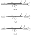
- Figure 2 shows the framed membrane electrode arrangement 4 with a frame sealing functional layer 11.
- the frame sealing functional layer 11 is the film composite made of the frame material, i.e. the frame 3, and the first elastomer layer 8 and the second elastomer layer 9.
- the first elastomer layer 8 is thicker than the second elastomer layer 9 is formed.
- first elastomer layer 8 and/or the second elastomer layer 9 only partially covers the edge region 7 of the frame 3.
- Figure 4 a further example is shown in which the first elastomer layer 8 covers a first region on the first side of the edge region 7 of the frame 3, while the second elastomer layer 9 covers a second region on the second side of the edge region 7 of the frame 3, wherein the covered regions are formed asymmetrically with respect to a longitudinal axis 10.
- first elastomer layer 8 may differ from the second elastomer layer 9 in its material and/or in its material composition.
- Figure 5 shows another fuel cell, which in contrast to the fuel cell according to Fig. 1 a second frame 17 with a second recess 18 in which the first gas diffusion layer 14 is accommodated.
- a third elastomer layer 19 formed as a film is arranged between the edge region of the second frame 17 and the first bipolar plate 5.
- the method for producing a fuel cell 1 comprises the following steps: providing a frame material formed as a first film, a first elastomer layer 8 formed as a second film and a second elastomer layer 9 formed as a third film.
- the films are each rolled up on a roll so that a roll process is possible.
- the individual layers i.e. the individual films, are placed on top of each other and connected to form a frame sealing functional layer 11 in such a way that on a first side of the frame material, i.e. the frame 3, the first elastomer layer 8 and on a side opposite the first the second elastomer layer 9 is arranged on the second side of the frame material.
- the layers can be applied and connected by calendering, spraying, pouring, printing or transferring.
- a further film is additionally provided as a second frame material for the second frame 17 and an additional third elastomer layer 19 formed as a film.
- the individual layers i.e. the individual films, are placed on top of one another and connected to form a frame sealing functional layer 11 in such a way that the first elastomer layer 8 is arranged on a first side of the frame material, i.e.
- the second elastomer layer 9 is arranged on a second side of the frame material opposite the first side, the second frame material is arranged on the side of the first elastomer layer 8 facing away from the membrane electrode arrangement 4, and the third elastomer layer 19 is arranged on the side of the second frame material facing away from the first elastomer layer 8.
- the layers can be applied and connected by calendering, spraying, pouring, printing or transferring.
- the frame sealing functional layer 11 is cut to individual frame elements and a recess 2 is cut out of the frame elements.
- the membrane electrode arrangement 4 is positioned in the recess 2 of the frame element and at least two bipolar plates 5, 6 are provided.
- the first bipolar plate 5 is positioned on the first side of the membrane electrode arrangement 4 and the second bipolar plate 6 is positioned on the second side of the membrane electrode arrangement 4 opposite the first side.
- a gas diffusion layer 14, 15 is arranged between the membrane electrode arrangement 4 and the bipolar plates 5, 6.
- the membrane electrode arrangement 4 is positively connected to the frame element and the bipolar plates 5, 6 as well as the gas diffusion layers 14, 15.
- connection can be materially bonded, ie by means of a binder.
- connection is achieved by mechanical pressure orthogonal to the bipolar plate 5,6, so that a detachable connection is achieved between the bipolar plate 5,6 and the frame element comprising the elastomer layers 8,9.
- the frame element or the composite of the bipolar plates 5,6, frame element and gas diffusion layers 14,15 can be treated with heat, ie with a temperature higher than the melting temperature of the elastomer, so that the elastomer layers 8,9 melt and penetrate into the roughness depth of the bipolar plates 5,6. This improves the sealing of the fuel cell 1.
- the first elastomer layer 8 and/or the second elastomer layer 9 is applied to the frame material only in certain areas by means of film transfer and adheres to it.
Landscapes
- Life Sciences & Earth Sciences (AREA)
- Engineering & Computer Science (AREA)
- Manufacturing & Machinery (AREA)
- Sustainable Development (AREA)
- Sustainable Energy (AREA)
- Chemical & Material Sciences (AREA)
- Chemical Kinetics & Catalysis (AREA)
- Electrochemistry (AREA)
- General Chemical & Material Sciences (AREA)
- Fuel Cell (AREA)
Claims (9)
- Pile à combustible (1) avec un agencement d'électrode de membrane (4) inséré dans un évidement (2) d'un cadre (3), au niveau du premier côté duquel une première plaque bipolaire (5) est agencée et au niveau du second côté duquel, opposé au premier côté, une seconde plaque bipolaire (6) est agencée, dans laquelle une zone de bord (7) du cadre (3) présente sur son côté tourné vers la première plaque bipolaire (5) une première couche en élastomère (8) formée comme deuxième film, la zone de bord (7) du cadre (3) présente sur son second côté tourné vers la seconde plaque bipolaire (6) une seconde couche en élastomère (9) formée comme troisième film, caractérisée en ce que la zone de bord (3) est formée comme un premier film, en ce que le cadre (3), la première couche en élastomère (8) et la seconde couche en élastomère (9) forment un assemblage de film, et en ce que les couches en élastomère (8, 9) agencées sur le cadre (3) sont conçues afin de rendre étanche en termes de mécanique fluidique les plaques bipolaires (5, 6) au moyen de la compensation de profondeur de rugosité et de l'élasticité fournie.
- Pile à combustible (1) selon la revendication 1, caractérisé en ce que la première couche en élastomère (8) et/ou la seconde couche en élastomère (9) recouvre seulement par endroits la zone de bord (7) du cadre.
- Pile à combustible (1) selon la revendication 1 ou 2, caractérisé en ce que la première couche en élastomère (8) recouvre une première zone sur le premier côté de la zone de bord (7) du cadre (3), en ce que la seconde couche en élastomère (9) recouvre une seconde zone sur le second côté de la zone de bord (7) du cadre (3) et en ce que les zones recouvertes sont formées de manière asymétrique par rapport à un axe longitudinal (10).
- Pile à combustible (1) selon l'une quelconque des revendications 1 à 3, caractérisée en ce que la première couche en élastomère (8) se distingue de la seconde couche en élastomère (9) en termes d'épaisseur et/ou de matériau utilisé.
- Procédé de fabrication d'une pile à combustible (1) selon l'une quelconque des revendications 1 à 4, comprenant les étapes suivantes :- la fourniture d'un matériau de cadre formé comme un premier film, d'une première couche en élastomère (8) formée comme un deuxième film et d'une seconde couche en élastomère (9) formé comme un troisième film,- la superposition et la liaison des couches en une couche fonctionnelle de joint d'étanchéité de cadre (11) de telle manière que la première couche en élastomère (8) soit agencée au niveau d'un premier côté du matériau de cadre et la seconde couche en élastomère (9) soit agencée au niveau d'un second côté opposé au premier côté,- la découpe de la couche fonctionnelle de joint d'étanchéité de cadre (11) en éléments de cadre individuels et la séparation d'un évidement (2) des éléments de cadre,- le positionnement de l'agencement d'électrode de membrane (4) dans l'évidement (2) de l'élément de cadre,- la fourniture de deux plaques bipolaires (5, 6) et le positionnement de la première plaque bipolaire (5) sur le premier côté de l'agencement d'électrode de membrane (4) et le positionnement de la seconde plaque bipolaire (6) sur le second côté opposé au premier côté de l'agencement d'électrode de membrane (4), et- la liaison par complémentarité de formes de l'agencement d'électrode de membrane (4) avec l'élément de cadre et les plaques bipolaires (5, 6).
- Procédé selon la revendication 5, caractérisé en ce que l'étape de liaison des couches en une couche fonctionnelle de joint d'étanchéité de cadre (11) est effectuée par impression, pulvérisation, coulage, calandrage ou transfert.
- Procédé selon la revendication 6, caractérisé en ce que la première couche en élastomère (8) et/ou la seconde couche en élastomère (9) colle au moyen du transfert de film seulement par endroits sur le matériau de cadre de telle manière que la couche fonctionnelle de joint d'étanchéité de cadre (11) présente seulement par endroits la première couche en élastomère et/ou la seconde couche en élastomère.
- Procédé selon l'une quelconque des revendications 5 à 7, caractérisé en ce que la première couche en élastomère (8) et la seconde couche en élastomère (9) présentent une épaisseur différente et/ou un matériau différent.
- Procédé selon l'une quelconque des revendications 5 à 8, caractérisé en ce que le matériau de cadre, la première couche en élastomère (8) et la seconde couche en élastomère (9) sont fournies enroulées respectivement sur un rouleau.
Applications Claiming Priority (2)
| Application Number | Priority Date | Filing Date | Title |
|---|---|---|---|
| DE102021113960.0A DE102021113960A1 (de) | 2021-05-31 | 2021-05-31 | Brennstoffzelle mit Elastomerschichten und Verfahren zur Herstellung einer Brennstoffzelle |
| PCT/EP2022/064149 WO2022253654A1 (fr) | 2021-05-31 | 2022-05-25 | Pile à combustible à couches d'élastomère et procédé de fabrication de pile à combustible |
Publications (2)
| Publication Number | Publication Date |
|---|---|
| EP4320657A1 EP4320657A1 (fr) | 2024-02-14 |
| EP4320657B1 true EP4320657B1 (fr) | 2025-02-12 |
Family
ID=82115759
Family Applications (1)
| Application Number | Title | Priority Date | Filing Date |
|---|---|---|---|
| EP22731517.3A Active EP4320657B1 (fr) | 2021-05-31 | 2022-05-25 | Pile à combustible à couches d'élastomère et procédé de fabrication de pile à combustible |
Country Status (5)
| Country | Link |
|---|---|
| US (1) | US20240274840A1 (fr) |
| EP (1) | EP4320657B1 (fr) |
| CN (1) | CN117425987A (fr) |
| DE (1) | DE102021113960A1 (fr) |
| WO (1) | WO2022253654A1 (fr) |
Family Cites Families (19)
| Publication number | Priority date | Publication date | Assignee | Title |
|---|---|---|---|---|
| DE4309976A1 (de) * | 1993-03-26 | 1994-09-29 | Daimler Benz Ag | Elektrochemische Mehrzellenbatterie |
| DE10152192B4 (de) * | 2001-10-23 | 2004-10-28 | Carl Freudenberg Kg | Verfahren zur Herstellung einer Träger-Dichtung |
| US8007949B2 (en) * | 2002-10-08 | 2011-08-30 | Bhaskar Sompalli | Edge-protected catalyst-coated diffusion media and membrane electrode assemblies |
| US7597983B2 (en) * | 2004-08-25 | 2009-10-06 | Gm Global Technology Operations, Inc. | Edge stress relief in diffusion media |
| DE202004017647U1 (de) * | 2004-11-13 | 2005-01-05 | Sartorius Ag | Brennstoffzellenstapel mit externer Medienversorgung |
| JP4096027B2 (ja) * | 2006-06-26 | 2008-06-04 | 松下電器産業株式会社 | 固体高分子電解質型燃料電池 |
| DE102011105072B3 (de) | 2011-06-21 | 2012-11-15 | Daimler Ag | Haltevorrichtung mit einer Membran einer Membran-Elektroden-Einheit für eine Brennstoffzelle und Verfahren zu deren Herstellung |
| DE102012020975A1 (de) * | 2012-10-25 | 2014-04-30 | Volkswagen Aktiengesellschaft | Membran-Elektroden-Anordnung, Brennstoffzelle mit einer solchen und Kraftfahrzeug mit der Brennstoffzelle |
| DE102012221730B4 (de) | 2012-11-28 | 2026-05-07 | Robert Bosch Gmbh | Verfahren zum Abdichten eines Kühlmittelraums einer Bipolarplatte einer Brennstoffzelle sowie Brennstoffzelle |
| DE102016202481A1 (de) * | 2016-02-18 | 2017-08-24 | Volkswagen Aktiengesellschaft | Brennstoffzellenstapel und Verfahren zum Herstellen eines solchen Brennstoffzellenstapels |
| GB2554387B (en) | 2016-09-23 | 2019-04-17 | Univ Cape Town | A fuel cell component |
| DE102016121614A1 (de) * | 2016-11-11 | 2018-05-17 | Audi Ag | Einzelzell-Anordnung für eine Brennstoffzelle und Brennstoffzellenstapel |
| DE102017101276A1 (de) * | 2017-01-24 | 2018-07-26 | Audi Ag | Bipolarplatten-Dichtungsanordnung sowie Brennstoffzellenstapel mit einer solchen |
| US20190273268A1 (en) | 2018-03-02 | 2019-09-05 | Honda Motor Co., Ltd. | Frame equipped membrane electrode assembly, method of producing the frame equipped membrane electrode assembly, and fuel cell |
| DE102018217291A1 (de) | 2018-10-10 | 2020-04-16 | Robert Bosch Gmbh | Verfahren zum Abdichten einer Brennstoffzelle |
| KR102683801B1 (ko) * | 2018-12-12 | 2024-07-09 | 현대자동차주식회사 | 연료전지용 탄성체 셀 프레임 및 그 제조방법과 이를 이용한 단위 셀 |
| KR102845708B1 (ko) * | 2019-05-16 | 2025-08-12 | 현대자동차주식회사 | 연료전지용 탄성체 셀 프레임 및 그 제조방법과 이를 이용한 연료전지 스택 |
| CN211980786U (zh) * | 2020-05-27 | 2020-11-20 | 未势能源科技有限公司 | 膜电极组件和具有它的燃料单电池 |
| CN112002923A (zh) | 2020-09-27 | 2020-11-27 | 上海文施绿极科技有限公司 | 燃料电池模块型边框膜 |
-
2021
- 2021-05-31 DE DE102021113960.0A patent/DE102021113960A1/de active Pending
-
2022
- 2022-05-25 US US18/561,577 patent/US20240274840A1/en active Pending
- 2022-05-25 CN CN202280035395.1A patent/CN117425987A/zh active Pending
- 2022-05-25 WO PCT/EP2022/064149 patent/WO2022253654A1/fr not_active Ceased
- 2022-05-25 EP EP22731517.3A patent/EP4320657B1/fr active Active
Also Published As
| Publication number | Publication date |
|---|---|
| WO2022253654A1 (fr) | 2022-12-08 |
| US20240274840A1 (en) | 2024-08-15 |
| CN117425987A (zh) | 2024-01-19 |
| EP4320657A1 (fr) | 2024-02-14 |
| DE102021113960A1 (de) | 2022-12-01 |
Similar Documents
| Publication | Publication Date | Title |
|---|---|---|
| DE19703214C2 (de) | Membran-Elektrodeneinheit mit integriertem Dichtrand und Verfahren zu ihrer Herstellung | |
| DE112005001826B4 (de) | Randgeschützte katalysatorbeschichtete Membranelektrodenanordnungen | |
| DE19983846B3 (de) | Protonenaustauschmembran-Brennstoffzellenanordnung mit thermoplastischen Folien zur Bildung von Dichtungen und zur Verbindung von Zellenkomponenten | |
| DE19829142A1 (de) | Gasdichter Verbund aus Bipolarplatte und Membran-Elektroden-Einheit von Polymerelektrolytmembran-Brennstoffzellen | |
| DE102018114003A1 (de) | Brennstoffzelle und verfahren zum herstellen derselben | |
| EP3496194A1 (fr) | Procédé de fabrication d'une unité membrane-électrode pourvue d'un joint d'étanchéité périphérique et unité membrane-électrode | |
| DE10207743A1 (de) | Elektrode für eine Polymerelektrolyt-Brennstoffzelle, Trennwand hierfür sowie Polymerelektrolyt-Brennstoffzelle und Elektrizitätserzeugungssystem unter Verwendung derselben | |
| EP4166691A1 (fr) | Cadre pour cellules d'électrolyse pem et empilement de cellules d'électrolyse pem destiné à la production de l'hydrogène à haute pression par électrolyse à pression différentielle | |
| EP1759434B2 (fr) | Module membrane-electrode (mea) pour pile a combustible | |
| WO2022084028A1 (fr) | Unité membrane-électrodes pour une cellule électrochimique, et procédé de fabrication d'une unité membrane-électrodes | |
| WO2020007735A1 (fr) | Dispositif électrochimique | |
| EP4320657A1 (fr) | Pile à combustible à couches d'élastomère et procédé de fabrication de pile à combustible | |
| WO2024227463A1 (fr) | Empilement de cellules électrochimiques et procédé de fonctionnement d'un empilement de cellules électrochimiques | |
| DE102018115997A1 (de) | Verfahren zum Herstellen einer elektrochemisch aktiven Einheit und Trägerelement für eine Baugruppe einer elektrochemisch aktiven Einheit | |
| WO2022242982A1 (fr) | Cellule électrochimique et procédé de fabrication d'une cellule électrochimique | |
| DE102021105017A1 (de) | Elektrochemische Einheit für eine elektrochemische Vorrichtung und Verfahren zum Herstellen einer elektrochemischen Einheit für eine elektrochemische Vorrichtung | |
| DE102021105029A1 (de) | Elektrochemische Einheit für eine elektrochemische Vorrichtung und Verfahren zum Herstellen einer elektrochemischen Einheit für eine elektrochemische Vorrichtung | |
| DE102023131979B4 (de) | Abgedichtete Membran-Elektrodeneinheit | |
| DE102022118477B3 (de) | Verfahren zur Herstellung einer mit einer Dichtung versehenen Membran-Elektrodenanordnung | |
| EP4150692B1 (fr) | Procédé pour la manufacture d'une structure stratifiée d'un assemblage membrane-électrode contenant au moins 2 couches | |
| WO2020109435A1 (fr) | Procédé de fabrication d'un agencement membrane-électrodes | |
| DE102025107614A1 (de) | Siebdruckvorrichtung zum Bedrucken zumindest einer Substratplatte | |
| DE102024127701A1 (de) | Verfahren zur Herstellung einer Membran-Elektrodeneinheit (MEA) für eine elektrochemische Zelle, insbesondere Brennstoffzelle, sowie Anlage zur Herstellung der MEA | |
| WO2026057271A1 (fr) | Cellule électrochimique | |
| DE102022206639A1 (de) | Stapelstruktur für einen elektrochemischen Energiewandler und Verfahren zum Herstellen der Stapelstruktur |
Legal Events
| Date | Code | Title | Description |
|---|---|---|---|
| STAA | Information on the status of an ep patent application or granted ep patent |
Free format text: STATUS: UNKNOWN |
|
| STAA | Information on the status of an ep patent application or granted ep patent |
Free format text: STATUS: THE INTERNATIONAL PUBLICATION HAS BEEN MADE |
|
| PUAI | Public reference made under article 153(3) epc to a published international application that has entered the european phase |
Free format text: ORIGINAL CODE: 0009012 |
|
| STAA | Information on the status of an ep patent application or granted ep patent |
Free format text: STATUS: REQUEST FOR EXAMINATION WAS MADE |
|
| 17P | Request for examination filed |
Effective date: 20231107 |
|
| AK | Designated contracting states |
Kind code of ref document: A1 Designated state(s): AL AT BE BG CH CY CZ DE DK EE ES FI FR GB GR HR HU IE IS IT LI LT LU LV MC MK MT NL NO PL PT RO RS SE SI SK SM TR |
|
| DAV | Request for validation of the european patent (deleted) | ||
| DAX | Request for extension of the european patent (deleted) | ||
| GRAP | Despatch of communication of intention to grant a patent |
Free format text: ORIGINAL CODE: EPIDOSNIGR1 |
|
| STAA | Information on the status of an ep patent application or granted ep patent |
Free format text: STATUS: GRANT OF PATENT IS INTENDED |
|
| INTG | Intention to grant announced |
Effective date: 20241202 |
|
| GRAS | Grant fee paid |
Free format text: ORIGINAL CODE: EPIDOSNIGR3 |
|
| GRAA | (expected) grant |
Free format text: ORIGINAL CODE: 0009210 |
|
| STAA | Information on the status of an ep patent application or granted ep patent |
Free format text: STATUS: THE PATENT HAS BEEN GRANTED |
|
| AK | Designated contracting states |
Kind code of ref document: B1 Designated state(s): AL AT BE BG CH CY CZ DE DK EE ES FI FR GB GR HR HU IE IS IT LI LT LU LV MC MK MT NL NO PL PT RO RS SE SI SK SM TR |
|
| REG | Reference to a national code |
Ref country code: GB Ref legal event code: FG4D Free format text: NOT ENGLISH |
|
| REG | Reference to a national code |
Ref country code: CH Ref legal event code: EP |
|
| REG | Reference to a national code |
Ref country code: DE Ref legal event code: R096 Ref document number: 502022002894 Country of ref document: DE |
|
| REG | Reference to a national code |
Ref country code: IE Ref legal event code: FG4D Free format text: LANGUAGE OF EP DOCUMENT: GERMAN |
|
| REG | Reference to a national code |
Ref country code: NL Ref legal event code: MP Effective date: 20250212 |
|
| PG25 | Lapsed in a contracting state [announced via postgrant information from national office to epo] |
Ref country code: RS Free format text: LAPSE BECAUSE OF FAILURE TO SUBMIT A TRANSLATION OF THE DESCRIPTION OR TO PAY THE FEE WITHIN THE PRESCRIBED TIME-LIMIT Effective date: 20250512 |
|
| PG25 | Lapsed in a contracting state [announced via postgrant information from national office to epo] |
Ref country code: FI Free format text: LAPSE BECAUSE OF FAILURE TO SUBMIT A TRANSLATION OF THE DESCRIPTION OR TO PAY THE FEE WITHIN THE PRESCRIBED TIME-LIMIT Effective date: 20250212 |
|
| PG25 | Lapsed in a contracting state [announced via postgrant information from national office to epo] |
Ref country code: PL Free format text: LAPSE BECAUSE OF FAILURE TO SUBMIT A TRANSLATION OF THE DESCRIPTION OR TO PAY THE FEE WITHIN THE PRESCRIBED TIME-LIMIT Effective date: 20250212 |
|
| PGFP | Annual fee paid to national office [announced via postgrant information from national office to epo] |
Ref country code: DE Payment date: 20250531 Year of fee payment: 4 |
|
| PG25 | Lapsed in a contracting state [announced via postgrant information from national office to epo] |
Ref country code: ES Free format text: LAPSE BECAUSE OF FAILURE TO SUBMIT A TRANSLATION OF THE DESCRIPTION OR TO PAY THE FEE WITHIN THE PRESCRIBED TIME-LIMIT Effective date: 20250212 |
|
| REG | Reference to a national code |
Ref country code: LT Ref legal event code: MG9D |
|
| PG25 | Lapsed in a contracting state [announced via postgrant information from national office to epo] |
Ref country code: NO Free format text: LAPSE BECAUSE OF FAILURE TO SUBMIT A TRANSLATION OF THE DESCRIPTION OR TO PAY THE FEE WITHIN THE PRESCRIBED TIME-LIMIT Effective date: 20250512 Ref country code: IS Free format text: LAPSE BECAUSE OF FAILURE TO SUBMIT A TRANSLATION OF THE DESCRIPTION OR TO PAY THE FEE WITHIN THE PRESCRIBED TIME-LIMIT Effective date: 20250612 |
|
| PG25 | Lapsed in a contracting state [announced via postgrant information from national office to epo] |
Ref country code: NL Free format text: LAPSE BECAUSE OF FAILURE TO SUBMIT A TRANSLATION OF THE DESCRIPTION OR TO PAY THE FEE WITHIN THE PRESCRIBED TIME-LIMIT Effective date: 20250212 |
|
| PG25 | Lapsed in a contracting state [announced via postgrant information from national office to epo] |
Ref country code: HR Free format text: LAPSE BECAUSE OF FAILURE TO SUBMIT A TRANSLATION OF THE DESCRIPTION OR TO PAY THE FEE WITHIN THE PRESCRIBED TIME-LIMIT Effective date: 20250212 |
|
| PG25 | Lapsed in a contracting state [announced via postgrant information from national office to epo] |
Ref country code: PT Free format text: LAPSE BECAUSE OF FAILURE TO SUBMIT A TRANSLATION OF THE DESCRIPTION OR TO PAY THE FEE WITHIN THE PRESCRIBED TIME-LIMIT Effective date: 20250612 Ref country code: LV Free format text: LAPSE BECAUSE OF FAILURE TO SUBMIT A TRANSLATION OF THE DESCRIPTION OR TO PAY THE FEE WITHIN THE PRESCRIBED TIME-LIMIT Effective date: 20250212 |
|
| PGFP | Annual fee paid to national office [announced via postgrant information from national office to epo] |
Ref country code: FR Payment date: 20250520 Year of fee payment: 4 |
|
| PG25 | Lapsed in a contracting state [announced via postgrant information from national office to epo] |
Ref country code: BG Free format text: LAPSE BECAUSE OF FAILURE TO SUBMIT A TRANSLATION OF THE DESCRIPTION OR TO PAY THE FEE WITHIN THE PRESCRIBED TIME-LIMIT Effective date: 20250212 Ref country code: GR Free format text: LAPSE BECAUSE OF FAILURE TO SUBMIT A TRANSLATION OF THE DESCRIPTION OR TO PAY THE FEE WITHIN THE PRESCRIBED TIME-LIMIT Effective date: 20250513 |
|
| PGFP | Annual fee paid to national office [announced via postgrant information from national office to epo] |
Ref country code: AT Payment date: 20250721 Year of fee payment: 4 |
|
| PG25 | Lapsed in a contracting state [announced via postgrant information from national office to epo] |
Ref country code: SE Free format text: LAPSE BECAUSE OF FAILURE TO SUBMIT A TRANSLATION OF THE DESCRIPTION OR TO PAY THE FEE WITHIN THE PRESCRIBED TIME-LIMIT Effective date: 20250212 |
|
| PG25 | Lapsed in a contracting state [announced via postgrant information from national office to epo] |
Ref country code: SM Free format text: LAPSE BECAUSE OF FAILURE TO SUBMIT A TRANSLATION OF THE DESCRIPTION OR TO PAY THE FEE WITHIN THE PRESCRIBED TIME-LIMIT Effective date: 20250212 |
|
| PG25 | Lapsed in a contracting state [announced via postgrant information from national office to epo] |
Ref country code: DK Free format text: LAPSE BECAUSE OF FAILURE TO SUBMIT A TRANSLATION OF THE DESCRIPTION OR TO PAY THE FEE WITHIN THE PRESCRIBED TIME-LIMIT Effective date: 20250212 |
|
| PG25 | Lapsed in a contracting state [announced via postgrant information from national office to epo] |
Ref country code: IT Free format text: LAPSE BECAUSE OF FAILURE TO SUBMIT A TRANSLATION OF THE DESCRIPTION OR TO PAY THE FEE WITHIN THE PRESCRIBED TIME-LIMIT Effective date: 20250212 |
|
| PG25 | Lapsed in a contracting state [announced via postgrant information from national office to epo] |
Ref country code: EE Free format text: LAPSE BECAUSE OF FAILURE TO SUBMIT A TRANSLATION OF THE DESCRIPTION OR TO PAY THE FEE WITHIN THE PRESCRIBED TIME-LIMIT Effective date: 20250212 Ref country code: CZ Free format text: LAPSE BECAUSE OF FAILURE TO SUBMIT A TRANSLATION OF THE DESCRIPTION OR TO PAY THE FEE WITHIN THE PRESCRIBED TIME-LIMIT Effective date: 20250212 |
|
| PG25 | Lapsed in a contracting state [announced via postgrant information from national office to epo] |
Ref country code: RO Free format text: LAPSE BECAUSE OF FAILURE TO SUBMIT A TRANSLATION OF THE DESCRIPTION OR TO PAY THE FEE WITHIN THE PRESCRIBED TIME-LIMIT Effective date: 20250212 |
|
| PG25 | Lapsed in a contracting state [announced via postgrant information from national office to epo] |
Ref country code: SK Free format text: LAPSE BECAUSE OF FAILURE TO SUBMIT A TRANSLATION OF THE DESCRIPTION OR TO PAY THE FEE WITHIN THE PRESCRIBED TIME-LIMIT Effective date: 20250212 |
|
| REG | Reference to a national code |
Ref country code: DE Ref legal event code: R097 Ref document number: 502022002894 Country of ref document: DE |
|
| P01 | Opt-out of the competence of the unified patent court (upc) registered |
Free format text: CASE NUMBER: UPC_APP_9785_4320657/2025 Effective date: 20251013 |
|
| PLBE | No opposition filed within time limit |
Free format text: ORIGINAL CODE: 0009261 |
|
| STAA | Information on the status of an ep patent application or granted ep patent |
Free format text: STATUS: NO OPPOSITION FILED WITHIN TIME LIMIT |
|
| REG | Reference to a national code |
Ref country code: CH Ref legal event code: H13 Free format text: ST27 STATUS EVENT CODE: U-0-0-H10-H13 (AS PROVIDED BY THE NATIONAL OFFICE) Effective date: 20251223 |
|
| REG | Reference to a national code |
Ref country code: CH Ref legal event code: L10 Free format text: ST27 STATUS EVENT CODE: U-0-0-L10-L00 (AS PROVIDED BY THE NATIONAL OFFICE) Effective date: 20251224 |
|
| PG25 | Lapsed in a contracting state [announced via postgrant information from national office to epo] |
Ref country code: LU Free format text: LAPSE BECAUSE OF NON-PAYMENT OF DUE FEES Effective date: 20250525 |
|
| PG25 | Lapsed in a contracting state [announced via postgrant information from national office to epo] |
Ref country code: CH Free format text: LAPSE BECAUSE OF NON-PAYMENT OF DUE FEES Effective date: 20250531 |
|
| 26N | No opposition filed |
Effective date: 20251113 |
|
| REG | Reference to a national code |
Ref country code: BE Ref legal event code: MM Effective date: 20250531 |
|
| PG25 | Lapsed in a contracting state [announced via postgrant information from national office to epo] |
Ref country code: MC Free format text: LAPSE BECAUSE OF FAILURE TO SUBMIT A TRANSLATION OF THE DESCRIPTION OR TO PAY THE FEE WITHIN THE PRESCRIBED TIME-LIMIT Effective date: 20250212 |
|
| PG25 | Lapsed in a contracting state [announced via postgrant information from national office to epo] |
Ref country code: IE Free format text: LAPSE BECAUSE OF NON-PAYMENT OF DUE FEES Effective date: 20250525 |
|
| PG25 | Lapsed in a contracting state [announced via postgrant information from national office to epo] |
Ref country code: BE Free format text: LAPSE BECAUSE OF NON-PAYMENT OF DUE FEES Effective date: 20250531 |