EP4320712B1 - Machine électrique - Google Patents
Machine électrique Download PDFInfo
- Publication number
- EP4320712B1 EP4320712B1 EP22711147.3A EP22711147A EP4320712B1 EP 4320712 B1 EP4320712 B1 EP 4320712B1 EP 22711147 A EP22711147 A EP 22711147A EP 4320712 B1 EP4320712 B1 EP 4320712B1
- Authority
- EP
- European Patent Office
- Prior art keywords
- stator
- rotor
- hydraulic
- electric machine
- connecting element
- Prior art date
- Legal status (The legal status is an assumption and is not a legal conclusion. Google has not performed a legal analysis and makes no representation as to the accuracy of the status listed.)
- Active
Links
Images
Classifications
-
- H—ELECTRICITY
- H02—GENERATION; CONVERSION OR DISTRIBUTION OF ELECTRIC POWER
- H02K—DYNAMO-ELECTRIC MACHINES
- H02K21/00—Synchronous motors having permanent magnets; Synchronous generators having permanent magnets
- H02K21/12—Synchronous motors having permanent magnets; Synchronous generators having permanent magnets with stationary armatures and rotating magnets
- H02K21/24—Synchronous motors having permanent magnets; Synchronous generators having permanent magnets with stationary armatures and rotating magnets with magnets axially facing the armatures, e.g. hub-type cycle dynamos
-
- H—ELECTRICITY
- H02—GENERATION; CONVERSION OR DISTRIBUTION OF ELECTRIC POWER
- H02K—DYNAMO-ELECTRIC MACHINES
- H02K15/00—Processes or apparatus specially adapted for manufacturing, assembling, maintaining or repairing of dynamo-electric machines
-
- H—ELECTRICITY
- H02—GENERATION; CONVERSION OR DISTRIBUTION OF ELECTRIC POWER
- H02K—DYNAMO-ELECTRIC MACHINES
- H02K16/00—Machines with more than one rotor or stator
- H02K16/04—Machines with one rotor and two stators
-
- H—ELECTRICITY
- H02—GENERATION; CONVERSION OR DISTRIBUTION OF ELECTRIC POWER
- H02K—DYNAMO-ELECTRIC MACHINES
- H02K5/00—Casings; Enclosures; Supports
- H02K5/04—Casings or enclosures characterised by the shape, form or construction thereof
- H02K5/22—Auxiliary parts of casings not covered by groups H02K5/06-H02K5/20, e.g. shaped to form connection boxes or terminal boxes
- H02K5/225—Terminal boxes or connection arrangements
-
- H—ELECTRICITY
- H02—GENERATION; CONVERSION OR DISTRIBUTION OF ELECTRIC POWER
- H02K—DYNAMO-ELECTRIC MACHINES
- H02K9/00—Arrangements for cooling or ventilating
- H02K9/19—Arrangements for cooling or ventilating for machines with closed casing and closed-circuit cooling using a liquid cooling medium, e.g. oil
- H02K9/197—Arrangements for cooling or ventilating for machines with closed casing and closed-circuit cooling using a liquid cooling medium, e.g. oil in which the rotor or stator space is fluid-tight, e.g. to provide for different cooling media for rotor and stator
Definitions
- the present invention relates to an electrical machine, in particular for an electrically operated drive train of a motor vehicle, comprising a rotor which is rotatably mounted relative to a stator, wherein the rotor has a rotor shaft with at least one first rotor body which is arranged on the rotor shaft in a rotationally and displacement-proof manner, wherein the stator comprises a first stator body and a second stator body which are spaced apart from one another and the first stator body has a first stator winding and the second stator body has a second stator winding, wherein the first stator winding is arranged within a first hydraulic chamber and the second stator winding is arranged within a second hydraulic chamber, within which the respective stator windings can each be contacted by a hydraulic fluid, at least in sections.
- Electric motors are increasingly being used to power motor vehicles, creating alternatives to combustion engines that require fossil fuels. Considerable efforts have already been made to improve the everyday suitability of electric drives and also to provide users with the same level of driving comfort they are accustomed to.
- hybrid drivetrains In addition to purely electric drivetrains, hybrid drivetrains are also known. Such drivetrains in hybrid vehicles typically comprise a combination of an internal combustion engine and an electric motor, enabling purely electric operation—for example, in urban areas—while maintaining sufficient range and availability, especially for long-distance journeys. Furthermore, in certain operating situations, it is possible to use both the internal combustion engine and the electric motor simultaneously.
- Jacket cooling and winding head cooling are known from the state of the art for cooling electrical machines using hydraulic fluids. While jacket cooling transfers the heat generated on the outer surface of the stator core into a cooling circuit, with winding head cooling, the heat is transferred directly to the fluid at the conductors outside the stator core in the area of the winding heads.
- the object of the invention is to provide an electrical machine that has a high power density through optimized cooling and an optimized electromagnetic design. Furthermore, the object of the invention is to ensure that the electrical machine is cost-effective to manufacture and easy to install.
- an electric machine in particular for an electrically operated drive train of a motor vehicle, comprising a rotor which is rotatably mounted relative to a stator, the rotor having a rotor shaft with at least one first rotor body which is arranged on the rotor shaft in a rotationally and displacement-proof manner, the stator comprising a first stator body and a second stator body which are spaced apart from one another and the first stator body has a first stator winding and the second stator body has a second stator winding, the first stator winding being arranged within a first hydraulic chamber or wet chamber and the second stator winding being arranged within a second hydraulic chamber or wet chamber, within which the respective stator windings can each be contacted by a hydraulic fluid or fluid, at least in sections, the electric machine comprising a hydraulic connecting element which hydraulically connects the first hydraulic chamber to the second hydraulic chamber, at least one electrical conductor of the first stator winding and/or the second stator winding
- the hydraulic connecting element can have any desired closed cross-sectional geometry and can be designed, for example, as a tube or hose for bridging one or more joints between a first hydraulic chamber of a first stator body and a second hydraulic chamber of a second stator body.
- This hydraulic connecting element also ensures that the electrical conductor of a stator winding is guided within it and simultaneously surrounded by the coolant.
- the hydraulic connecting element can preferably be inserted or fitted into existing openings. Furthermore, the hydraulic connecting element can be used to adjust air and creepage distances within the electrical machine.
- the sealing effect of the hydraulic connecting element with adjacent housing parts can be achieved, for example, by a defined gap between the sealing element and the housing, by pressing the hydraulic connecting element in the sealing area with adjacent housing parts, or by using a separate sealing element or sealant.
- the sealing element can preferably also be integrated into the hydraulic connecting element for a sealed and electrically insulated feedthrough.
- Electrical machines are used to convert electrical energy into mechanical energy and/or vice versa, and usually comprise a stationary part known as a stator, stand or armature, and a part known as a rotor or runner, which is arranged to move relative to the stationary part.
- a distinction is made in particular between radial flux machines and axial flux machines.
- a radial flux machine is characterized by the fact that the Magnetic field lines in the air gap formed between the rotor and stator extend in the radial direction, whereas in the case of an axial flux machine, the magnetic field lines in the air gap formed between the rotor and stator extend in the axial direction.
- the electrical machine according to the invention can be designed as an axial flux machine or a radial flux machine.
- the stator of the electrical machine can in particular be designed as a stator for a radial flux machine.
- the stator of a radial flux machine is usually cylindrical and preferably consists of electrically insulated, layered, and stacked laminations. Distributed around the circumference, grooves and/or channels can be cut into the electrical lamination, running parallel to the rotor shaft, to accommodate the stator winding or parts of the stator winding.
- the stator designed for a radial flux machine can be designed as a stator for an inner rotor or an outer rotor. In an inner rotor, for example, the stator teeth extend radially inwards, while in an outer rotor they extend radially outwards.
- the electric machine according to the invention is intended in particular for use within a drive train of a hybrid or fully electric motor vehicle.
- the electric machine is dimensioned such that vehicle speeds greater than 50 km/h, preferably greater than 80 km/h, and in particular greater than 100 km/h can be achieved.
- the electric machine particularly preferably has an output greater than 30 kW, preferably greater than 50 kW, and in particular greater than 70 kW. It is further preferred that the electric machine provides rotational speeds greater than 5,000 rpm or 1/min, particularly preferably greater than 10,000 rpm, and most preferably greater than 12,500 rpm.
- a stator winding is an electrically conductive conductor whose length is significantly greater than its length perpendicular to the longitudinal extension.
- the stator winding can, in principle, have any cross-sectional shape. Rectangular cross-sectional shapes are preferred, as they allow for high packing and, consequently, power densities.
- a The stator winding is formed from copper.
- a stator winding preferably has insulation.
- mica paper which may be reinforced with a glass fabric backing for mechanical reasons, can be wound in strip form around one or more stator windings impregnated with a curable resin. In principle, it is also possible to use a curable polymer or a lacquer layer without mica paper to insulate a stator winding.
- the electrical machine is designed as an axial flux machine, comprising the rotor rotatably mounted relative to the stator in a dry space, wherein the rotor has the rotor shaft with at least the first disc-shaped rotor body arranged on the rotor shaft in a rotationally and displacement-proof manner, wherein the stator comprises the first annular disc-shaped stator body and the second annular disc-shaped stator body, which are arranged coaxially to one another and to the rotor shaft and are axially spaced from one another with the rotor arranged therebetween.
- the electrical machine can thus be designed to be very compact axially.
- the magnetic flux in such an electric axial flux machine is directed axially to a direction of rotation of the rotor of the axial flux machine in the air gap between stator and rotor.
- AFM electric axial flux machine
- I-arrangement in which the rotor is arranged axially next to a stator or between two stators.
- H-arrangement in which two rotors are arranged on opposite axial sides of a stator. In the context of the present invention, an I-arrangement is preferred.
- the hydraulic connecting element is made of an electrically non-conductive material. This can achieve a good electrical insulation effect can be provided to electrically conductive components of the electrical machine.
- the hydraulic connecting element has a substantially cylindrical ring-like spatial shape.
- the hydraulic connecting element is positioned radially above the first stator body and/or the second stator body.
- the invention can also be further developed such that the hydraulic connecting element has a first seal that seals the first hydraulic chamber from the dry chamber of the rotor, and/or the hydraulic connecting element has a second seal that seals the second hydraulic chamber from the dry chamber of the rotor.
- the first seal and/or the second seal are/is formed integrally with the hydraulic connecting element.
- the hydraulic connecting element is connected by means of a press fit to a first housing component that at least partially delimits the first hydraulic chamber and/or the hydraulic connecting element is connected by means of a press fit to a second housing component that at least partially delimits the second hydraulic chamber.
- a plurality of hydraulic connecting elements are arranged circumferentially distributed between the first hydraulic chamber and the second hydraulic chamber.
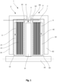
- the electric machine 1 comprises a rotor 3 which is rotatably mounted relative to a stator 2, wherein the rotor 3 has a rotor shaft 30 with at least one first rotor body 31 which is arranged on the rotor shaft 30 in a rotationally and displacement-proof manner.
- the stator 2 has a first stator body 21 and a second stator body 22 which are spaced apart from one another in the axial direction, wherein the first stator body 21 has a first stator winding 41 and the second stator body 22 has a second stator winding 42, wherein the first stator winding 41 is arranged within a first hydraulic chamber 51 and the second stator winding 42 is arranged within a second hydraulic chamber 52, within which the respective stator windings 41, 42 can each be contacted by a hydraulic fluid 5, at least in sections.
- the electric machine 1 further comprises a plurality of hydraulic connecting elements 6, which hydraulically connect the first hydraulic chamber 51 to the second hydraulic chamber 52. At least one electrical conductor 7 of the second stator winding 42 is arranged within each of the hydraulic connecting elements 6.
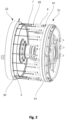
- the plurality of substantially identical executed hydraulic connecting elements 6 is arranged circumferentially distributed between the first hydraulic chamber 51 and the second hydraulic chamber 52, which is particularly well understood from the synopsis of Figure 1 with the Figure 2 becomes apparent.
- the electrical machine is designed as an axial flux machine 1 with the rotor 3 which is mounted rotatably relative to the stator 2 in a dry space 32.
- the rotor 3 comprises the rotor shaft 30 with at least the first disc-shaped rotor body 31 which is arranged on the rotor shaft 30 in a rotationally and displacement-proof manner.
- the stator 2 has the first annular disc-shaped stator body 21 and the second annular disc-shaped stator body 22, which are arranged coaxially to one another and to the rotor shaft 30 and are axially spaced from one another with the rotor 3 arranged therebetween.
- the first stator winding 41 has first winding ends emerging from the first stator body 21, which extend radially above the stator body 21 in the axial direction.
- the second stator winding 42 also has second winding ends emerging from the second stator body 22, which extend radially above the first stator body 21 and the second stator body 22 in the axial direction. From the synopsis of Figure 1 with the Figure 2 It is further apparent that the first hydraulic chamber 51 is at least partially enclosed by a delimiting first housing component 91, which has a plurality of circumferentially distributed openings for the passage of the second winding ends.
- the first winding ends are arranged on a circular path with a first diameter and the second winding ends are arranged on a circular path with a second diameter, wherein the first diameter is different from the second diameter.
- the first winding ends and the second winding ends are oriented toward the same axial end face of the axial flux machine 1 and are connected to the same axial end face of the axial flux machine 1.
- the first stator winding 41 and the second stator winding 42 are each configured as three-phase with a star point connection.
- the hydraulic connecting element 6 is formed from an electrically non-conductive material and has a substantially cylindrical ring-like spatial shape. In the embodiment shown, the hydraulic connecting elements 6 are positioned radially above the first stator body 21 and the second stator body 22.
- a hydraulic connecting element 6 has a first seal 81 which seals the first hydraulic chamber 51 from the dry chamber 32 of the rotor 2, and the hydraulic connecting element 6 has a second seal 82 which seals the second hydraulic chamber 52 from the dry chamber 32 of the rotor 2.
- the first seal 81 and the second seal 82 are designed as sealing rings in the embodiment shown, which is particularly evident from the Figure 2 is evident.
- the hydraulic connecting elements 6 are each connected by means of a press fit to a first housing component 91 which at least partially delimits the first hydraulic chamber 51 and to a second housing component 92 which at least partially delimits the second hydraulic chamber 52.
Landscapes
- Engineering & Computer Science (AREA)
- Power Engineering (AREA)
- Manufacturing & Machinery (AREA)
- Motor Or Generator Frames (AREA)
Claims (10)
- Machine électrique (1), en particulier pour une chaîne cinématique actionnée électriquement d'un véhicule automobile, comprenant un rotor (3) qui est monté rotatif par rapport à un stator (2), le rotor (3) présentant un arbre de rotor (30) comportant au moins un premier corps de rotor (31) agencé sur l'arbre de rotor (30) de manière fixe en rotation et en déplacement, le stator (2) comprenant un premier corps de stator (21) et un second corps de stator (22) qui sont espacés l'un de l'autre, et le premier corps de stator (21) présentant un premier enroulement de stator (41) et le second corps de stator (22) présentant un second enroulement de stator (42), le premier enroulement de stator (41) étant agencé à l'intérieur d'une première chambre hydraulique (51) et le second enroulement de stator (42) étant agencé à l'intérieur d'une seconde chambre hydraulique (52), à l'intérieur desquelles les enroulements de stator (41, 42) respectifs peuvent chacun être mis en contact, au moins par sections, avec un fluide hydraulique (5), caractérisée en ce que
la machine électrique (1) comprend un élément de liaison hydraulique (6) qui relie hydrauliquement la première chambre hydraulique (51) à la seconde chambre hydraulique (52), au moins un conducteur électrique (7) du premier enroulement de stator (41) et/ou du second enroulement de stator (42) étant agencé à l'intérieur de l'élément de liaison hydraulique (6). - Machine électrique (1) selon la revendication 1,
caractérisée en ce que
la machine électrique est conçue comme une machine à flux axial (1), comprenant le rotor (3) monté rotatif, dans une chambre sèche (32), par rapport au stator (2), le rotor (3) présentant l'arbre de rotor (30) comportant au moins le premier corps de rotor (31) conçu en forme de disque qui est agencé sur l'arbre de rotor (30) de manière fixe en rotation et en déplacement, le stator (2) comprenant le premier corps de stator (21) en forme de disque et le second corps de stator (22) en forme de disque, qui sont agencés coaxialement l'un par rapport à l'autre et par rapport à l'arbre de rotor (30) et qui sont espacés axialement l'un de l'autre, le rotor (3) étant agencé entre eux. - Machine électrique (1) selon l'une quelconque des revendications précédentes, caractérisée en ce que
l'élément de liaison hydraulique (6) est réalisé en un matériau électriquement non conducteur. - Machine électrique (1) selon l'une quelconque des revendications précédentes, caractérisée en ce que
l'élément de liaison hydraulique (6) présente une forme spatiale sensiblement en anneau cylindrique. - Machine électrique (1) selon l'une quelconque des revendications précédentes, caractérisée en ce que
l'élément de liaison hydraulique (6) est positionné radialement au-dessus du premier corps de stator (21) et/ou du second corps de stator (22). - Machine électrique (1) selon l'une quelconque des revendications précédentes, caractérisée en ce que
l'élément de liaison hydraulique (6) présente un premier joint (81) qui scelle la première chambre hydraulique (51) par rapport à la chambre sèche (32) du rotor (3) et/ou l'élément de liaison hydraulique (6) présente un second joint (82) qui scelle la seconde chambre hydraulique (52) par rapport à la chambre sèche (32) du rotor (3). - Machine électrique (1) selon la revendication 6,
caractérisée en ce que
le premier joint (81) et/ou le second joint (82) sont conçus d'un seul tenant avec l'élément de liaison hydraulique (6). - Machine électrique (1) selon l'une quelconque des revendications précédentes, caractérisée en ce que
l'élément de liaison hydraulique (6) est relié par ajustement serré à un premier élément de boîtier (91) délimitant au moins par sections la première chambre hydraulique (51) et/ou l'élément de liaison hydraulique (6) est relié par ajustement serré à un second élément de boîtier (92) délimitant au moins par sections la seconde chambre hydraulique (52). - Machine électrique (1) selon l'une quelconque des revendications précédentes, caractérisée en ce que
une pluralité d'éléments de liaison hydraulique (6) sont agencés de façon à être répartis circonférentiellement entre la première chambre hydraulique (51) et la seconde chambre hydraulique (52). - Machine électrique (1) selon l'une quelconque des revendications précédentes, caractérisée en ce que
les éléments de liaison hydraulique (6) sont réalisés de façon sensiblement identique.
Applications Claiming Priority (2)
| Application Number | Priority Date | Filing Date | Title |
|---|---|---|---|
| DE102021108949.2A DE102021108949A1 (de) | 2021-04-10 | 2021-04-10 | Elektrische Maschine |
| PCT/DE2022/100182 WO2022214121A1 (fr) | 2021-04-10 | 2022-03-08 | Machine électrique |
Publications (2)
| Publication Number | Publication Date |
|---|---|
| EP4320712A1 EP4320712A1 (fr) | 2024-02-14 |
| EP4320712B1 true EP4320712B1 (fr) | 2025-06-11 |
Family
ID=80786556
Family Applications (1)
| Application Number | Title | Priority Date | Filing Date |
|---|---|---|---|
| EP22711147.3A Active EP4320712B1 (fr) | 2021-04-10 | 2022-03-08 | Machine électrique |
Country Status (5)
| Country | Link |
|---|---|
| US (1) | US12549072B2 (fr) |
| EP (1) | EP4320712B1 (fr) |
| CN (1) | CN117121348A (fr) |
| DE (1) | DE102021108949A1 (fr) |
| WO (1) | WO2022214121A1 (fr) |
Families Citing this family (1)
| Publication number | Priority date | Publication date | Assignee | Title |
|---|---|---|---|---|
| FR3146248A1 (fr) * | 2023-02-23 | 2024-08-30 | Michel Raoul | Machine électrique à flux magnétique axial équipée d'un double dispositif de refroidissement. |
Family Cites Families (7)
| Publication number | Priority date | Publication date | Assignee | Title |
|---|---|---|---|---|
| US5982070A (en) * | 1996-12-27 | 1999-11-09 | Light Engineering Corporation | Electric motor or generator having amorphous core pieces being individually accomodated in a dielectric housing |
| CN1294770A (zh) * | 1998-03-19 | 2001-05-09 | 莱特工程公司 | 电动机或发电机 |
| US9755463B2 (en) | 2015-08-11 | 2017-09-05 | Genesis Robotics Llp | Electric machine |
| DE102015013018A1 (de) | 2015-10-07 | 2017-04-13 | Audi Ag | Stator für eine elektrische Maschine |
| EP3157138B1 (fr) | 2015-10-12 | 2018-07-25 | Siemens Aktiengesellschaft | Procede de refroidissement d'un paquet de toles, paquet de toles, rotor, stator et machine electrique |
| GB2546255A (en) | 2016-01-07 | 2017-07-19 | Mclaren Automotive Ltd | Cooling electric machines |
| KR20250067960A (ko) * | 2018-06-15 | 2025-05-15 | 인디고 테크놀로지스, 인크. | 일체형 냉각 기능을 갖는 밀폐식 축 방향 자속 모터 |
-
2021
- 2021-04-10 DE DE102021108949.2A patent/DE102021108949A1/de active Pending
-
2022
- 2022-03-08 CN CN202280027284.6A patent/CN117121348A/zh active Pending
- 2022-03-08 WO PCT/DE2022/100182 patent/WO2022214121A1/fr not_active Ceased
- 2022-03-08 EP EP22711147.3A patent/EP4320712B1/fr active Active
- 2022-03-08 US US18/554,564 patent/US12549072B2/en active Active
Also Published As
| Publication number | Publication date |
|---|---|
| WO2022214121A1 (fr) | 2022-10-13 |
| EP4320712A1 (fr) | 2024-02-14 |
| DE102021108949A1 (de) | 2022-10-13 |
| CN117121348A (zh) | 2023-11-24 |
| US20240204621A1 (en) | 2024-06-20 |
| US12549072B2 (en) | 2026-02-10 |
Similar Documents
| Publication | Publication Date | Title |
|---|---|---|
| WO2022188916A1 (fr) | Stator et procédé de production d'un stator | |
| WO2023110002A1 (fr) | Stator de machine électrique doté de fentes de stator destinées à un enroulement de stator, un écoulement de fluide de refroidissement étant possible à travers au moins l'une des fentes de stator | |
| DE102021109437A1 (de) | Stator und Verfahren zur Herstellung eines Stators | |
| DE102021106613A1 (de) | Stator und Verfahren zur Herstellung eines Stators | |
| WO2024046521A1 (fr) | Stator | |
| DE102021108952B4 (de) | Elektrische Maschine | |
| WO2023143659A1 (fr) | Stator | |
| EP4320714A1 (fr) | Machine électrique | |
| WO2022214121A1 (fr) | Machine électrique | |
| WO2024230883A1 (fr) | Stator, machine électrique et chaîne cinématique | |
| DE102021108950A1 (de) | Elektrische Maschine | |
| WO2024046522A1 (fr) | Stator et ensemble de pièces | |
| DE102022127198A1 (de) | Stator und elektrische Maschine | |
| DE102021104824A1 (de) | Stator und Verfahren zur Herstellung eines Stators | |
| DE102021108905A1 (de) | Elektrische Maschine | |
| DE102023105136B4 (de) | Stator, Verfahren zur Herstellung eines Stators, Fluidleitkörper und elektrische Maschine | |
| DE102023101615B4 (de) | Stator | |
| DE102023110325B4 (de) | Stator, Rotor, elektrische Maschine und Verfahren zur Herstellung eines Stators und Verfahren zur Herstellung eines Rotors | |
| DE102021115529A1 (de) | Elektrische Maschine | |
| EP4674036A1 (fr) | Stator et machine électrique | |
| DE102022128179A1 (de) | Stator und Verfahren zur Herstellung eines Stators | |
| DE102024129542A1 (de) | Stirnseitige Scheibe mit einem Ringkanal für einen Rotor einer elektrischen Maschine, insbesondere eines extern erregten Synchronmotors | |
| WO2025098564A1 (fr) | Ensemble rotor et machine électrique | |
| DE102022108817A1 (de) | Elektromotor mit Mantelkühlung | |
| WO2024222992A1 (fr) | Stator pour une machine électrique et procédé de production d'un stator |
Legal Events
| Date | Code | Title | Description |
|---|---|---|---|
| STAA | Information on the status of an ep patent application or granted ep patent |
Free format text: STATUS: UNKNOWN |
|
| STAA | Information on the status of an ep patent application or granted ep patent |
Free format text: STATUS: THE INTERNATIONAL PUBLICATION HAS BEEN MADE |
|
| PUAI | Public reference made under article 153(3) epc to a published international application that has entered the european phase |
Free format text: ORIGINAL CODE: 0009012 |
|
| STAA | Information on the status of an ep patent application or granted ep patent |
Free format text: STATUS: REQUEST FOR EXAMINATION WAS MADE |
|
| 17P | Request for examination filed |
Effective date: 20231110 |
|
| AK | Designated contracting states |
Kind code of ref document: A1 Designated state(s): AL AT BE BG CH CY CZ DE DK EE ES FI FR GB GR HR HU IE IS IT LI LT LU LV MC MK MT NL NO PL PT RO RS SE SI SK SM TR |
|
| DAV | Request for validation of the european patent (deleted) | ||
| DAX | Request for extension of the european patent (deleted) | ||
| GRAP | Despatch of communication of intention to grant a patent |
Free format text: ORIGINAL CODE: EPIDOSNIGR1 |
|
| STAA | Information on the status of an ep patent application or granted ep patent |
Free format text: STATUS: GRANT OF PATENT IS INTENDED |
|
| INTG | Intention to grant announced |
Effective date: 20250228 |
|
| GRAS | Grant fee paid |
Free format text: ORIGINAL CODE: EPIDOSNIGR3 |
|
| GRAA | (expected) grant |
Free format text: ORIGINAL CODE: 0009210 |
|
| STAA | Information on the status of an ep patent application or granted ep patent |
Free format text: STATUS: THE PATENT HAS BEEN GRANTED |
|
| AK | Designated contracting states |
Kind code of ref document: B1 Designated state(s): AL AT BE BG CH CY CZ DE DK EE ES FI FR GB GR HR HU IE IS IT LI LT LU LV MC MK MT NL NO PL PT RO RS SE SI SK SM TR |
|
| REG | Reference to a national code |
Ref country code: GB Ref legal event code: FG4D Free format text: NOT ENGLISH |
|
| REG | Reference to a national code |
Ref country code: CH Ref legal event code: EP |
|
| REG | Reference to a national code |
Ref country code: DE Ref legal event code: R096 Ref document number: 502022004246 Country of ref document: DE |
|
| REG | Reference to a national code |
Ref country code: IE Ref legal event code: FG4D Free format text: LANGUAGE OF EP DOCUMENT: GERMAN |
|
| PG25 | Lapsed in a contracting state [announced via postgrant information from national office to epo] |
Ref country code: FI Free format text: LAPSE BECAUSE OF FAILURE TO SUBMIT A TRANSLATION OF THE DESCRIPTION OR TO PAY THE FEE WITHIN THE PRESCRIBED TIME-LIMIT Effective date: 20250611 Ref country code: ES Free format text: LAPSE BECAUSE OF FAILURE TO SUBMIT A TRANSLATION OF THE DESCRIPTION OR TO PAY THE FEE WITHIN THE PRESCRIBED TIME-LIMIT Effective date: 20250611 |
|
| REG | Reference to a national code |
Ref country code: LT Ref legal event code: MG9D |
|
| PG25 | Lapsed in a contracting state [announced via postgrant information from national office to epo] |
Ref country code: GR Free format text: LAPSE BECAUSE OF FAILURE TO SUBMIT A TRANSLATION OF THE DESCRIPTION OR TO PAY THE FEE WITHIN THE PRESCRIBED TIME-LIMIT Effective date: 20250912 Ref country code: NO Free format text: LAPSE BECAUSE OF FAILURE TO SUBMIT A TRANSLATION OF THE DESCRIPTION OR TO PAY THE FEE WITHIN THE PRESCRIBED TIME-LIMIT Effective date: 20250911 |
|
| REG | Reference to a national code |
Ref country code: NL Ref legal event code: MP Effective date: 20250611 |
|
| PG25 | Lapsed in a contracting state [announced via postgrant information from national office to epo] |
Ref country code: BG Free format text: LAPSE BECAUSE OF FAILURE TO SUBMIT A TRANSLATION OF THE DESCRIPTION OR TO PAY THE FEE WITHIN THE PRESCRIBED TIME-LIMIT Effective date: 20250611 |
|
| PG25 | Lapsed in a contracting state [announced via postgrant information from national office to epo] |
Ref country code: HR Free format text: LAPSE BECAUSE OF FAILURE TO SUBMIT A TRANSLATION OF THE DESCRIPTION OR TO PAY THE FEE WITHIN THE PRESCRIBED TIME-LIMIT Effective date: 20250611 |
|
| PG25 | Lapsed in a contracting state [announced via postgrant information from national office to epo] |
Ref country code: RS Free format text: LAPSE BECAUSE OF FAILURE TO SUBMIT A TRANSLATION OF THE DESCRIPTION OR TO PAY THE FEE WITHIN THE PRESCRIBED TIME-LIMIT Effective date: 20250911 |
|
| PG25 | Lapsed in a contracting state [announced via postgrant information from national office to epo] |
Ref country code: LV Free format text: LAPSE BECAUSE OF FAILURE TO SUBMIT A TRANSLATION OF THE DESCRIPTION OR TO PAY THE FEE WITHIN THE PRESCRIBED TIME-LIMIT Effective date: 20250611 |
|
| PG25 | Lapsed in a contracting state [announced via postgrant information from national office to epo] |
Ref country code: NL Free format text: LAPSE BECAUSE OF FAILURE TO SUBMIT A TRANSLATION OF THE DESCRIPTION OR TO PAY THE FEE WITHIN THE PRESCRIBED TIME-LIMIT Effective date: 20250611 |
|
| PG25 | Lapsed in a contracting state [announced via postgrant information from national office to epo] |
Ref country code: PT Free format text: LAPSE BECAUSE OF FAILURE TO SUBMIT A TRANSLATION OF THE DESCRIPTION OR TO PAY THE FEE WITHIN THE PRESCRIBED TIME-LIMIT Effective date: 20251013 |
|
| PG25 | Lapsed in a contracting state [announced via postgrant information from national office to epo] |
Ref country code: IS Free format text: LAPSE BECAUSE OF FAILURE TO SUBMIT A TRANSLATION OF THE DESCRIPTION OR TO PAY THE FEE WITHIN THE PRESCRIBED TIME-LIMIT Effective date: 20251011 |
|
| PG25 | Lapsed in a contracting state [announced via postgrant information from national office to epo] |
Ref country code: SM Free format text: LAPSE BECAUSE OF FAILURE TO SUBMIT A TRANSLATION OF THE DESCRIPTION OR TO PAY THE FEE WITHIN THE PRESCRIBED TIME-LIMIT Effective date: 20250611 |
|
| PG25 | Lapsed in a contracting state [announced via postgrant information from national office to epo] |
Ref country code: CZ Free format text: LAPSE BECAUSE OF FAILURE TO SUBMIT A TRANSLATION OF THE DESCRIPTION OR TO PAY THE FEE WITHIN THE PRESCRIBED TIME-LIMIT Effective date: 20250611 |
|
| PG25 | Lapsed in a contracting state [announced via postgrant information from national office to epo] |
Ref country code: PL Free format text: LAPSE BECAUSE OF FAILURE TO SUBMIT A TRANSLATION OF THE DESCRIPTION OR TO PAY THE FEE WITHIN THE PRESCRIBED TIME-LIMIT Effective date: 20250611 |
|
| PG25 | Lapsed in a contracting state [announced via postgrant information from national office to epo] |
Ref country code: EE Free format text: LAPSE BECAUSE OF FAILURE TO SUBMIT A TRANSLATION OF THE DESCRIPTION OR TO PAY THE FEE WITHIN THE PRESCRIBED TIME-LIMIT Effective date: 20250611 |
|
| PG25 | Lapsed in a contracting state [announced via postgrant information from national office to epo] |
Ref country code: SK Free format text: LAPSE BECAUSE OF FAILURE TO SUBMIT A TRANSLATION OF THE DESCRIPTION OR TO PAY THE FEE WITHIN THE PRESCRIBED TIME-LIMIT Effective date: 20250611 |
|
| REG | Reference to a national code |
Ref country code: DE Ref legal event code: R097 Ref document number: 502022004246 Country of ref document: DE |
|
| PGFP | Annual fee paid to national office [announced via postgrant information from national office to epo] |
Ref country code: GB Payment date: 20260324 Year of fee payment: 5 |
|
| PG25 | Lapsed in a contracting state [announced via postgrant information from national office to epo] |
Ref country code: DK Free format text: LAPSE BECAUSE OF FAILURE TO SUBMIT A TRANSLATION OF THE DESCRIPTION OR TO PAY THE FEE WITHIN THE PRESCRIBED TIME-LIMIT Effective date: 20250611 |
|
| PGFP | Annual fee paid to national office [announced via postgrant information from national office to epo] |
Ref country code: DE Payment date: 20260331 Year of fee payment: 5 |
|
| PGFP | Annual fee paid to national office [announced via postgrant information from national office to epo] |
Ref country code: AT Payment date: 20260301 Year of fee payment: 5 |
|
| PG25 | Lapsed in a contracting state [announced via postgrant information from national office to epo] |
Ref country code: IT Free format text: LAPSE BECAUSE OF FAILURE TO SUBMIT A TRANSLATION OF THE DESCRIPTION OR TO PAY THE FEE WITHIN THE PRESCRIBED TIME-LIMIT Effective date: 20250611 |
|
| PLBE | No opposition filed within time limit |
Free format text: ORIGINAL CODE: 0009261 |
|
| STAA | Information on the status of an ep patent application or granted ep patent |
Free format text: STATUS: NO OPPOSITION FILED WITHIN TIME LIMIT |
|
| PGFP | Annual fee paid to national office [announced via postgrant information from national office to epo] |
Ref country code: FR Payment date: 20260323 Year of fee payment: 5 |
|
| REG | Reference to a national code |
Ref country code: CH Ref legal event code: L10 Free format text: ST27 STATUS EVENT CODE: U-0-0-L10-L00 (AS PROVIDED BY THE NATIONAL OFFICE) Effective date: 20260423 |