EP4320722B1 - Demi-produit de boîte de connexion, demi-produit de module solaire, module solaire et procédé de production d'un module solaire - Google Patents
Demi-produit de boîte de connexion, demi-produit de module solaire, module solaire et procédé de production d'un module solaire Download PDFInfo
- Publication number
- EP4320722B1 EP4320722B1 EP22724409.2A EP22724409A EP4320722B1 EP 4320722 B1 EP4320722 B1 EP 4320722B1 EP 22724409 A EP22724409 A EP 22724409A EP 4320722 B1 EP4320722 B1 EP 4320722B1
- Authority
- EP
- European Patent Office
- Prior art keywords
- solar module
- finished product
- semi
- housing
- connection socket
- Prior art date
- Legal status (The legal status is an assumption and is not a legal conclusion. Google has not performed a legal analysis and makes no representation as to the accuracy of the status listed.)
- Active
Links
Images


Classifications
-
- H—ELECTRICITY
- H02—GENERATION; CONVERSION OR DISTRIBUTION OF ELECTRIC POWER
- H02S—GENERATION OF ELECTRIC POWER BY CONVERSION OF INFRARED RADIATION, VISIBLE LIGHT OR ULTRAVIOLET LIGHT, e.g. USING PHOTOVOLTAIC [PV] MODULES
- H02S40/00—Components or accessories in combination with PV modules, not provided for in groups H02S10/00 - H02S30/00
- H02S40/30—Electrical components
- H02S40/34—Electrical components comprising specially adapted electrical connection means to be structurally associated with the PV module, e.g. junction boxes
-
- H—ELECTRICITY
- H02—GENERATION; CONVERSION OR DISTRIBUTION OF ELECTRIC POWER
- H02S—GENERATION OF ELECTRIC POWER BY CONVERSION OF INFRARED RADIATION, VISIBLE LIGHT OR ULTRAVIOLET LIGHT, e.g. USING PHOTOVOLTAIC [PV] MODULES
- H02S40/00—Components or accessories in combination with PV modules, not provided for in groups H02S10/00 - H02S30/00
- H02S40/30—Electrical components
- H02S40/36—Electrical components characterised by special electrical interconnection means between two or more PV modules, e.g. electrical module-to-module connection
-
- H—ELECTRICITY
- H10—SEMICONDUCTOR DEVICES; ELECTRIC SOLID-STATE DEVICES NOT OTHERWISE PROVIDED FOR
- H10F—INORGANIC SEMICONDUCTOR DEVICES SENSITIVE TO INFRARED RADIATION, LIGHT, ELECTROMAGNETIC RADIATION OF SHORTER WAVELENGTH OR CORPUSCULAR RADIATION
- H10F19/00—Integrated devices, or assemblies of multiple devices, comprising at least one photovoltaic cell covered by group H10F10/00, e.g. photovoltaic modules
- H10F19/90—Structures for connecting between photovoltaic cells, e.g. interconnections or insulating spacers
- H10F19/902—Structures for connecting between photovoltaic cells, e.g. interconnections or insulating spacers for series or parallel connection of photovoltaic cells
-
- Y—GENERAL TAGGING OF NEW TECHNOLOGICAL DEVELOPMENTS; GENERAL TAGGING OF CROSS-SECTIONAL TECHNOLOGIES SPANNING OVER SEVERAL SECTIONS OF THE IPC; TECHNICAL SUBJECTS COVERED BY FORMER USPC CROSS-REFERENCE ART COLLECTIONS [XRACs] AND DIGESTS
- Y02—TECHNOLOGIES OR APPLICATIONS FOR MITIGATION OR ADAPTATION AGAINST CLIMATE CHANGE
- Y02E—REDUCTION OF GREENHOUSE GAS [GHG] EMISSIONS, RELATED TO ENERGY GENERATION, TRANSMISSION OR DISTRIBUTION
- Y02E10/00—Energy generation through renewable energy sources
- Y02E10/50—Photovoltaic [PV] energy
Definitions
- the invention relates to a junction box semi-finished product and a solar module semi-finished product which can be connected to one another to produce the solar module, to a solar module comprising the junction box semi-finished product and the solar module semi-finished product, and to a method for producing the solar module.
- a solar module typically comprises a plate-shaped front element, a plate-shaped rear element, and an encapsulation material arranged between the front element and the rear element.
- the solar module further comprises a plurality of solar cell strings made up of solar cells that are usually electrically connected in series. These solar cells are arranged between the front element and the rear element and are permanently encapsulated in a weather-resistant manner in an encapsulation volume in the form of a solar module laminate by means of the front element, the rear element, and the encapsulation material surrounding the solar cells.
- the solar cell strings are typically electrically interconnected within the laminate using electrical conductor elements, particularly in the form of cross connectors.
- the electrical interconnection can be a pure series connection of the solar cell strings or a combination of series and parallel connections of solar cell strings.
- the interconnected solar cell strings have electrical connection elements, of which at least one positive terminal connection element and one negative terminal connection element are led out of the encapsulation volume through an opening formed in the rear element.
- a junction box is also fixed to the solar module in the area of this opening for permanently weather-resistant, sealed electrical contact with the electrical connection elements led out of the encapsulation volume.
- the junction box has a housing into which the connection elements are inserted and which can also be filled with a filling material to provide the connection elements with permanent weather-resistant protection against moisture and corrosion.
- the junction box is connected to a first solar module cable.
- the solar module is provided with a positive pole cable and a second solar module cable as the negative pole cable, which are electrically connected to the positive and negative pole connection elements in the junction box.
- the electrical energy generated by the solar module can be dissipated via the first and second solar module cables.
- a solar module that has two positive pole contact elements and two negative pole contact elements, as well as several junction boxes designed for contacting a solar cell string, each with a positive pole contact element and a negative pole contact element. Three junction boxes are each electrically connected via box cables, and the solar module has two solar module cables.
- a solar panel with a solar module, an input junction box, an output junction box, and electrical conductors extending from the solar module. Two of the electrical conductors are connected to the already attached input junction box, and two of the electrical conductors are connected to the already attached output junction box. Six additional electrical conductors extend from the solar module and are yet to be connected by jumper boxes.
- the input junction box is bonded to the solar module by means of an input junction box fastener, and an input junction box cover may be bonded to the solar module.
- the input junction box fastener includes electrical and/or electronic components.
- junction box semi-finished product and the solar module semi-finished product can be prefabricated in a simple manner.
- a ready-to-use solar module is obtained by mounting the junction box semi-finished product according to the invention on the solar module semi-finished product according to the invention.
- the junction box sub-housings of the junction box semi-finished product and the corresponding housing bases of the solar module semi-finished product are permanently and weather-resistantly connected to form at least two junction boxes.
- the solar cell strings assigned to the two junction boxes inside the solar module laminate are electrically interconnected by means of a box cable running outside the solar module laminate between the housings. Unlike in the prior art, the interconnection of the solar cell strings takes place entirely or partially outside the solar module laminate.
- junction box semi-finished product with its at least two junction box sub-housings when connected to the solar module semi-finished product, provides simple interconnection of the solar cell strings of the solar module semi-finished product.
- the junction box semi-finished product can be easily prefabricated before assembly on the solar module semi-finished product. This production can take place in a separate production facility, for example, by a supplier.
- the at least two junction box sub-housings represent two structurally separate sub-housings of two different junction boxes, but are electrically interconnected via the box cable. This design eliminates the need for the integration and lamination of electrical conductor elements such as cross connectors for electrically interconnecting the solar cell strings inside the solar module laminate of the solar module semi-finished product.
- both the first solar module cable and the second solar module cable are connected to the first contact device, while the at least one further contact device is not connected to any solar module cable, ie, the at least one further contact device is designed without a solar module cable.
- the first junction box sub-housing when mounted on a solar module semi-finished product, is then part of a main junction box of the solar module thus formed.
- Leading from this main junction box are Solar module cables in the form of a negative pole cable for the solar module and a positive pole cable for the solar module, which allow the solar module to be connected to other solar modules.
- At least one additional junction box sub-housing then becomes part of a satellite junction box, which, when the solar module is in operation, can conduct the electrical current generated by its associated solar cell strings via the junction box cable to the main junction box.
- the first or further contact device(s) each comprise a first or further positive pole contact element and a first or further negative pole contact element.
- the respective contact device can consist exclusively of the respective positive pole contact element and the respective negative pole contact element.
- the respective contact device can comprise, in addition to the respective positive pole contact element and the respective negative pole contact element, further structural and functional components, such as an electrical contact strip and electronic components.
- the electrical interconnections described above are each a series connection.
- the at least one socket cable establishes a series connection between the first contact device of the first junction box sub-housing and the at least one further contact device of the at least one further junction box sub-housing.
- other variants are also possible and can be implemented more easily via the external electrical interconnection of the solar cell strings using the junction box semi-finished product.
- the first and/or the at least one further junction box sub-housing further contain one or more electrical and/or electronic components.
- the electrical and/or electronic components are replaceable in the first and/or at least one further Junction box sub-housings are arranged. This means that in the event of a defect, only the defective component does not need to be replaced, but rather the affected junction box sub-housing.
- all electrical and/or electronic components are arranged in the first junction box sub-housing, which, when integrated into the solar module, forms part of the main junction box, while the other junction box sub-housings are free of electrical and/or electronic components with the exception of the mandatory positive and negative pole contact elements.
- the first junction box sub-housing contains at least one bypass diode for one or more solar cell strings of a solar module laminate.
- the at least one further junction box sub-housing preferably contains at least one bypass diode for a solar cell string of a solar module. If current no longer flows in one or more solar cell strings during operation of the solar module, for example due to contamination or shading, the bypass diode can prevent overheating and defects.
- the first junction box sub-housing contains at least one bypass diode for at least one solar cell string of a solar module laminate, and the first contact device is electrically connected to the first solar module cable and the second solar module cable.
- the at least one further junction box sub-housing is bypass diode-free, and the at least one further contact device is not connected to the first solar module cable and the second solar module cable, i.e., it is designed to be solar module cable-free.
- the first junction box sub-housing comprises control and/or analysis electronics for a solar module.
- the at least one further junction box sub-housing comprises control and/or analysis electronics for a solar module.
- the first junction box sub-housing is provided with control and/or analysis electronics for a solar module is formed, while the at least one further junction box sub-housing is free of control and/or analysis electronics.
- the first junction box sub-housing is formed in one piece.
- the at least one further junction box sub-housing is preferably formed in one piece. More preferably, the first junction box sub-housing and the at least one further junction box sub-housing are each formed in one piece. This further simplifies the assembly for producing the solar module.
- first junction box sub-housing and/or the at least one further junction box sub-housing are each trough-shaped. This provides sufficient space for electrical and/or electronic components that can be integrated into it or them.
- the first junction box sub-housing and the at least one further junction box sub-housing have socket locking elements configured to engage with corresponding locking elements of a first housing base or a further housing base of a semi-finished solar module. This allows the solar module to be easily manufactured using a simple yet secure connection method.
- the solar cell strings are connected by means of the at least two housing bases in conjunction with the junction box semi-finished product, which has at least one box cable in order to electrically connect the solar cell strings outside the laminate in the desired manner.
- the solar module laminate of the solar module semi-finished product is preferably designed without cross-connectors; i.e., it has electrical conductor elements in the form of cross-connectors inside the solar module laminate.
- electrical conductor elements for forming the solar cell strings themselves are No additional electrical conductor elements are required to interconnect the solar cell strings within the solar module laminate. This makes it easier and more cost-effective to manufacture than conventional solar modules and semi-finished solar modules.
- the openings in the rear side element of the semi-finished solar module are positioned such that they lie over a starting section and an end section of at least one solar cell string. This allows the pair of terminals to be easily led out of the solar module laminate through the opening in a comparatively short path.
- the first housing base and the at least one further housing base have further locking elements designed to engage with the first junction box sub-housing or the further junction box sub-housing of the junction box semi-finished product. This allows a permanently weather-resistant junction box to be easily produced.
- the first and at least one further housing base are fixed to the rear side element, for example, glued thereto. This allows them to be applied to the rear side element in a simple and automated manner during production of the solar module semi-finished product.
- the first and at least one further housing base are preferably plate-shaped.
- the first and at least one further housing base are free of electrical and/or electronic components, apart from the fact that the electrical connection pair of the associated solar cell strings is passed through them.
- the first housing base and the at least one further housing base each have at least one hole through which the connection element(s) of the solar cell strings can be passed.
- junction box semi-finished product and its electrical components can be easily replaced if necessary, for example in the event of a defect.
- first junction box sub-housing is arranged and fixed on the first housing base and the further junction box sub-housing is arranged and fixed on the further housing base in such a way that they form a first junction box or a further junction box, each of which is permanently sealed in a weatherproof manner.
- the first junction box sub-housing and the first housing base form the first junction box
- the at least one further junction box sub-housing and the at least one further housing base form the at least one further junction box.
- the first junction box is preferably the main junction box
- the at least one further junction box is preferably a satellite junction box.
- a main junction box within the meaning of the invention is a junction box that is electrically connected to the first solar module cable and the second solar module cable
- a satellite junction box is a junction box that is not electrically connected to a solar module cable, i.e., it is designed without a solar module cable. Since the satellite junction box is connected to the main junction box via at least one junction box cable, it is able to conduct current into the main junction box during operation.
- the solar module preferably has a main junction box and two satellite junction boxes.
- the positive and negative terminal connection elements of the solar cell strings and the positive and negative terminal connection elements of the junction box semi-finished product are designed to be complementary in such a way that when the junction box semi-finished product is placed on the solar module semi-finished product, form electrical contact.
- they are electrically connected by means of a plug connection.
- the positive and negative terminal connection elements of the junction box semi-finished product are designed as female receptacle elements, and the positive and negative terminal connection elements of the solar cell strings are designed as male plug elements.
- the solar module semi-finished product and the solar module are preferably designed as a wafer solar module semi-finished product or as a wafer solar module.
- a wafer solar module differs from a thin-film solar module in particular in that it comprises wafer-based solar cells rather than thin-film solar cells.
- Wafer-based solar cells have a thickness greater than 100 ⁇ m or, for example, in the range of 180 to 300 ⁇ m, while thin-film solar cells have a thickness in the range of a few ⁇ m.
- the solar cells can be half, third, quarter, fifth, or full cells.
- connection creates the first junction box described above and at least one further junction box described above.
- Fig. 1 shows a sectional view of a junction box semi-finished product according to the invention parallel to a module plane defined by an associated solar module semi-finished product.
- the junction box semi-finished product for a solar module semi-finished product has a first junction box partial housing 1, which accommodates a first contact device 11 with a first positive pole contact element 12 and with a first negative pole contact element 13 and a bypass diode 4.
- the first positive pole contact element 12 and the first negative pole contact element 13 are arranged and designed for electrically contacting one or more positive pole connection elements (not shown) and one or more negative pole connection elements (not shown) of solar cell strings (not shown) that are led out of the solar module laminate of a solar module semi-finished product.
- the bypass diode 4 is arranged and designed in the first contact device 11 for one or more solar cell strings of a solar module semi-finished product.
- the junction box semi-finished product further comprises a further junction box sub-housing 2, which accommodates a further contact device 21 with a further positive pole contact element 22 and a further negative pole contact element 23, and a further bypass diode 4.
- the further positive pole contact element 22 and the further negative pole contact element 23 are arranged and configured for electrically contacting one or more positive pole connection elements (not shown) and one or more negative pole connection elements (not shown) of solar cell strings made from the solar module laminate of a solar module semi-finished product (not shown).
- the bypass diode 4 is arranged and configured for one or more solar cell strings of the solar module semi-finished product.
- the first junction box sub-housing 1 and the further junction box sub-housing 2 are structurally separate from one another.
- junction box semi-finished product has a socket cable 31, which establishes an electrical connection between the first contact device 11 of the first junction box sub-housing 1 and the further contact device 21 of the further junction box sub-housing 2.
- the junction box semi-finished product further comprises a first solar module cable 32 which is connected to the further contact device 21 in such a way that the solar module cable 32 forms a positive pole connection which is electrically connected to the first contact device 11 and the further contact device 21 via the at least one box cable 31.
- the junction box semi-finished product has a second solar module cable 32' which is connected to the first contact device 11 in such a way that the further solar module cable 32' forms a negative pole connection which is electrically connected to the first contact device 11 and the further contact device 21 via the at least one box cable 31.
- the first junction box sub-housing 1 and the further junction box sub-housing 2 each have box locking elements 3, which are each structurally are designed to engage with complementarily designed locking elements of housing bases (not shown) of a solar module semi-finished product.
- Fig. 2 shows an electrical circuit diagram of another junction box semi-finished product according to the invention.
- Fig. 2 The semi-finished junction box shown corresponds to the Fig. 1 shown junction box semi-finished product with the difference that, in addition to a first further junction box sub-housing 2, it has a further second junction box sub-housing 2'.
- the first junction box sub-housing 1 has two further bypass diodes 4, while the first further junction box sub-housing 2 and also the second further junction box sub-housing 2' each do not contain a solar cell string bypass diode.
- the solar module cable 32 is connected to the first junction box sub-housing 1 instead of to the first further junction box sub-housing 2.
- the further junction box sub-housing 2' has a further contact device 21 with a further positive pole contact element 22 and a further negative pole contact element 23.
- the further positive pole contact element 22 and the further negative pole contact element 23 are arranged and configured for electrically contacting one or more positive pole connection elements (not shown) and one or more negative pole connection elements (not shown) of solar cell strings (not shown) of a solar module laminate.
- the first junction box sub-housing 1 and the further junction box sub-housings 2, 2' are structurally separate from one another.
- Fig. 3 shows a sectional view of an embodiment of a solar module semi-finished product according to the invention perpendicular to a module plane defined by the solar module semi-finished product.
- the solar module semi-finished product has a plate-shaped front side element 6 and a plate-shaped rear side element 5. Three openings 9 are formed in the rear side element 5, one of which is shown.
- the solar module semi-finished product has an encapsulation material 88 arranged between the front side element 6 and the rear side element 5.
- Arranged in the encapsulation material 88 are a plurality of solar cell strings (not shown) made of electrically interconnected solar cells 8.
- the solar cell strings are permanently weather-resistant encapsulated in an encapsulation volume by means of the front side element 6, the rear side element 5 and the encapsulation material 88 surrounding the solar cells 8 in the form of a solar module laminate.
- the solar cell strings have positive pole connection elements 71 and negative pole connection elements 72, which are each led out of the encapsulation volume through one of the three openings 9 per solar cell string as a connection pair in the form of the positive pole connection element 71 and the associated negative pole connection element 72, wherein the connection pairs are each led out through the spatially closest of the at least two openings 9 and there is no electrical contact between the solar cell strings within the laminate.
- the solar module semi-finished product further comprises a first housing base 50, which is fixed over one of the three openings 9 on the rear side element 5, for example by means of adhesive 51, and is designed to produce a permanently weatherproof housing in conjunction with a mounted junction box sub-housing (not shown).
- the first housing base has holes (not shown) through which the connection elements 71, 72 of solar cell strings are guided as a connection pair.
- the first housing base has base locking elements 7, which are designed to engage with locking elements 3 of the Fig. 2 shown first junction box sub-housing 1.
- Fig. 4 shows a top view of the Fig. 3 shown solar module semi-finished product.
- the solar module semi-finished product has three pairs of solar cell strings 80. These are shown purely schematically as loops above and below three openings 9 on the back of the solar module semi-finished product.
- the positive terminal connection elements 71 and negative terminal connection elements 72 of the solar cell strings 80 are each led out of the solar module laminate of the solar module semi-finished product through one of the three openings 9.
- the solar module semi-finished product has two further housing bases 52, which are used to produce a permanently weatherproof junction box in conjunction with a further Junction box sub-housings (not shown) are formed.
- the further housing bases 52 are each fixed above one of the other two openings 9 on the rear element 5.
- the openings 9 are shown in dashed lines because, in this plan view, they are located below the housing bases 50, 52 and are therefore concealed.
- the Fig. 3 and 4 shown solar module semi-finished product and then the Fig. 2
- the three-part junction box semi-finished product shown is arranged such that the first housing base 50 of the solar module semi-finished product is connected to the first junction box sub-housing 1 by latching, and the two further housing bases 52 of the solar module semi-finished product are each connected to one of the two further junction box sub-housings 2 by latching.
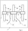
- This solar module is shown by way of example in Fig. 5 shown.
- the three-part junction box semi-finished product with its partial housings (1, 2, 2') together with the associated housing bases (50, 52), forms permanently weatherproof, closed housings, and the box cables 31 between these housings connect the solar cell strings 80 arranged inside the solar module laminate in the desired electrical circuit outside the solar module laminate.
Landscapes
- Photovoltaic Devices (AREA)
Claims (11)
- Un produit semi-fini de boîte de jonction pour un module solaire,- un premier sous-boîtier de boîte de jonction (1), qui comporte un dispositif de premier contact (11) avec un premier élément de contact de pôle positif (12) et un premier élément de contact de pôle négatif (13), agencé et conçu de telle manière pour contacter électriquement un ou plusieurs éléments de connexion de pôle positif (71) et un ou plusieurs éléments de connexion de pôle négatif (72) de chaînes de cellules solaires (80) d'un stratifié de module solaire,- au moins un autre sous-boîtier de boîte de jonction (2,2'), qui comporte un autre dispositif de contact (21) avec un autre élément de contact de pôle positif (22) et un autre élément de contact de pôle négatif (23), agencé et conçu de telle manière pour contacter électriquement un ou plusieurs éléments de connexion de pôle positif (71) et un ou plusieurs éléments de connexion de pôle négatif (72) de chaînes de cellules solaires (80) d'un stratifié de module solaire, dans lequel le premier sous-boîtier de boîte de jonction (1) et le au moins un ou les autres sous-boîtiers de boîte de jonction (2,2') sont structurellement séparés les uns des autres,- au moins un câble de boîte (31) qui établit une connexion électrique entre le premier dispositif de contact (11) du premier sous-boîtier de boîte de jonction (1) et l'autre dispositif de contact (21) de l'autre sous-boîtier de boîte de jonction (2),- un premier câble de module solaire (32) qui est connecté au premier dispositif de contact (11) ou au ou à l'un des autres dispositifs de contact (21) de telle sorte que le premier câble de module solaire (32) forme une connexion de pôle positive du dispositif de premier contact (11) relié par au moins un câble de boîte (31) en interconnexion électrique et de l'autre dispositif de contact (21) ou des autres dispositifs de contact (21), et- un second câble de module solaire (32') qui est connecté au premier dispositif de contact (11) ou au ou à l'un des autres dispositifs de contact (21) de telle sorte que le second câble de module solaire (32') forme une connexion de pôle négative du premier dispositif de contact (11) relié par au moins un câble de boîte (31) en interconnexion électrique et de l'autre dispositif de contact (21) ou des autres dispositifs de contact (21').
- Le produit semi-fini de boîte de jonction selon la revendication 1, caractérisée en ce que le premier sous-boîtier de boîte de jonction (1) contient au moins une diode de dérivation (4) pour une chaîne de cellules solaires (80) d'un stratifié de module solaire et/ou que le au moins un autre sous-boîtier de boîte de jonction (2,2') contient au moins une diode de dérivation (4) pour une chaîne de cellules solaires (80) d'un stratifié de module solaire.
- Le produit semi-fini de boîte de jonction selon la revendication 1 ou 2, caractérisée en ce que le premier sous-boîtier de boîte de jonction (1) comporte de l'électronique de commande et/ou d'analyse pour un module solaire et/ou que le au moins un autre sous-boîtier de boîte de jonction (2,2') comporte de l'électronique de commande et/ou d'analyse pour un module solaire.
- Le produit semi-fini de boîte de jonction selon l'une quelconque des revendications précédentes, caractérisé en ce que le premier sous-boîtier de boîte de jonction (1) et/ou le ou les au moins un autre sous-boîtier de boîte de jonction (2,2') sont chacun d'une seule pièce.
- Le produit semi-fini de boîte de jonction selon l'une quelconque des revendications précédentes, caractérisés en ce que le premier sous-boîtier de boîte de jonction (1) et/ou le au moins un autre sous-boîtier de boîte de jonction (2,2') sont chacun en forme de cuvette.
- Un produit semi-fini de module solaire, comportant- un élément avant en forme de plaque (6) et un élément arrière en forme de plaque (5), dans lesquels l'élément arrière (5) comporte au moins deux ouvertures (9),- un matériau d'encapsulation (88) qui est disposé entre l'élément avant (6) et l'élément arrière (5),- une pluralité de chaînes de cellules solaires (80) constituées de cellules solaires (8) interconnectées électriquement, qui sont disposées entre l'élément avant (6) et l'élément arrière (5) et sont encapsulées de manière résistante aux intempéries au moyen de l'élément avant (6), de l'élément arrière (5) et du matériau d'encapsulation (88) enfermant les cellules solaires (8) sous la forme d'un stratifié de module solaire dans un volume d'encapsulation,- des éléments de connexion aux pôles positifs (71) et des éléments de connexion aux pôles négatifs (72) des chaînes de cellules solaires (80), qui sont sortis hors du volume d'encapsulation par l'une des au moins deux ouvertures (9) par chaîne de cellules solaires (80) en tant que paire de connexion sous la forme d'un élément de connexion de pôle positif (71) et d'un élément de connexion de pôle négatif correspondant (72), dans lequel les paires de connexion sont chacune sorties par l'ouverture la plus voisinée spatialement des au moins deux ouvertures (9) et il n'y a pas de un contact électrique entre les chaînes de cellules solaires (80) dans le stratifié,- une première base de boîtier (50) fixée au produit semi-fini de module solaire par l'intermédiaire d'une des au moins deux ouvertures (9), conçue pour une production d'un boîtier durablement résistant aux intempéries en conjonction avec un sous-boîtier de boîte de jonction attaché (1), et- au moins une autre base de boîtier (52) fixée au-dessus de l'autre des au moins deux ouvertures (9) du produit semi-fini de module solaire, conçue pour la production d'un boîtier durablement résistant aux intempéries en conjonction avec un autre sous-boîtier boîte de jonction (2) attaché,dans lequel la première et au moins une autre base de boîtier est exempte de composants électriques et/ou électroniques, à l'exception du fait que la paire de connexion électrique des chaînes de cellules solaires attribuées est acheminée à travers celle-ci.
- Le produit semi-fini de module solaire selon la revendication 6, caractérisé en ce que les ouvertures (9) sont positionnées dans l'élément arrière (5) de telle manière qu'elles viennent se situer au-dessus d'une partie initiale et au-dessus d'une partie finale d'au moins une chaîne de cellules solaires (80).
- Le produit semi-fini de boîte de jonction selon l'une quelconque des revendications 1 à 5 ou le produit semi-fini de module solaire selon la revendication 6 ou 7, caractérisé en ce que le premier sous-boîtier de boîte de jonction (1) et le ou les autres sous-boîtiers de boîte de jonction (2,2') ont des éléments d'encliquetage de boîte (3) qui sont conçus pour s'engager avec la première base de boîtier (50) ou l'autre base de boîte (52) du produit semi-fini de module solaire ou que la première base de boîtier (50) et la ou les autres bases de boîtier (52) comportent d'autres éléments d'encliquetage de base (7) qui sont conçus pour s'engager avec le premier sous-boîtier de boîte de jonction (1) ou l'autre sous-boîtier de boîte de jonction (2).
- Un module solaire comportant un produit semi-fini de module solaire selon l'une quelconque des revendications 6 à 8 et un produit semi-fini de boîte de jonction selon l'une des revendications 1 à 5 ou 8, monté sur la première base de boîtier (50) et sur l'autre base de boîtier (52).
- Le module solaire selon la revendication 9, caractérisé en ce que le sous-boîtier de la boîte de jonction (1) est disposé et fixé sur la première base du boîtier (50) et l'autre sous-boîtier de la boîte de jonction (2) est disposé et fixé sur l'autre base de boîtier (52) de telle manière qu'ils forment une boîte de jonction ou une autre boîte de jonction, chacune d'entre elles étant étanche de façon permanente et résistante aux intempéries.
- Un procédé de production d'un module solaire, comportant des étapes suivantes- fournir un produit semi-fini de module solaire selon l'une des revendications 6 à 8,- disposer un produit semi-fini de boîte de jonction selon l'une quelconque des revendications 1 à 5 ou 8, de sorte que la première base de boîtier (50) du produit semi-fini de module solaire soit connectée au premier sous-boîtier de boîte de jonction (1) et que la ou les autres bases de boîtier (52) du produit semi-fini de module solaire soient connectées au ou des autres sous-boîtiers de boîte de jonction (2).
Applications Claiming Priority (2)
| Application Number | Priority Date | Filing Date | Title |
|---|---|---|---|
| DE102021108875.5A DE102021108875A1 (de) | 2021-04-09 | 2021-04-09 | Anschlussdosen-Halbzeug, Solarmodul-Halbzeug, Solarmodul und Verfahren zur Herstellung eines Solarmoduls |
| PCT/DE2022/100255 WO2022214139A1 (fr) | 2021-04-09 | 2022-04-04 | Demi-produit de boîte de connexion, demi-produit de module solaire, module solaire et procédé de production d'un module solaire |
Publications (2)
| Publication Number | Publication Date |
|---|---|
| EP4320722A1 EP4320722A1 (fr) | 2024-02-14 |
| EP4320722B1 true EP4320722B1 (fr) | 2025-06-04 |
Family
ID=81749123
Family Applications (1)
| Application Number | Title | Priority Date | Filing Date |
|---|---|---|---|
| EP22724409.2A Active EP4320722B1 (fr) | 2021-04-09 | 2022-04-04 | Demi-produit de boîte de connexion, demi-produit de module solaire, module solaire et procédé de production d'un module solaire |
Country Status (7)
| Country | Link |
|---|---|
| US (1) | US20240204721A1 (fr) |
| EP (1) | EP4320722B1 (fr) |
| CN (1) | CN117529877A (fr) |
| DE (1) | DE102021108875A1 (fr) |
| ES (1) | ES3040362T3 (fr) |
| PL (1) | PL4320722T3 (fr) |
| WO (1) | WO2022214139A1 (fr) |
Families Citing this family (1)
| Publication number | Priority date | Publication date | Assignee | Title |
|---|---|---|---|---|
| DE102022128839A1 (de) * | 2022-10-31 | 2024-05-02 | Weidmüller Interface GmbH & Co. KG | Photovoltaikmodul und Anschlussanordnung für ein Photovoltaikmodul |
Family Cites Families (9)
| Publication number | Priority date | Publication date | Assignee | Title |
|---|---|---|---|---|
| DE102009022944A1 (de) * | 2009-05-27 | 2010-12-02 | Yamaichi Electronics Deutschland Gmbh | Anschluß- oder Überbrückungsdose mit Lötmitteldepot |
| CN201699031U (zh) | 2010-04-20 | 2011-01-05 | 泰科电子(上海)有限公司 | 太阳能光伏组件 |
| CN101958351B (zh) * | 2010-04-20 | 2013-05-15 | 常州天合光能有限公司 | 具有多接线盒的太阳电池组件 |
| US20120152325A1 (en) * | 2010-06-21 | 2012-06-21 | Global Solar Energy, Inc. | Junction box attachment to solar module laminate |
| EP2769418A1 (fr) | 2011-10-19 | 2014-08-27 | Saint-Gobain Glass France | Module solaire à conducteur en ruban plat ainsi que son procédé de fabrication |
| WO2015098203A1 (fr) * | 2013-12-27 | 2015-07-02 | パナソニックIpマネジメント株式会社 | Module de cellule solaire |
| CN106788218A (zh) * | 2016-12-28 | 2017-05-31 | 南通美能得新能源科技股份有限公司 | 一种多接线盒太阳能组件 |
| CN110729964B (zh) | 2018-07-17 | 2021-09-21 | 浙江英达威芯电子有限公司 | 一种光伏系统及其光伏组件 |
| CN109327187A (zh) * | 2018-11-16 | 2019-02-12 | 浙江中环赛特光伏科技有限公司 | 一种光伏接线盒 |
-
2021
- 2021-04-09 DE DE102021108875.5A patent/DE102021108875A1/de not_active Ceased
-
2022
- 2022-04-04 US US18/554,493 patent/US20240204721A1/en active Pending
- 2022-04-04 WO PCT/DE2022/100255 patent/WO2022214139A1/fr not_active Ceased
- 2022-04-04 ES ES22724409T patent/ES3040362T3/es active Active
- 2022-04-04 CN CN202280041463.5A patent/CN117529877A/zh active Pending
- 2022-04-04 PL PL22724409.2T patent/PL4320722T3/pl unknown
- 2022-04-04 EP EP22724409.2A patent/EP4320722B1/fr active Active
Also Published As
| Publication number | Publication date |
|---|---|
| CN117529877A (zh) | 2024-02-06 |
| EP4320722A1 (fr) | 2024-02-14 |
| PL4320722T3 (pl) | 2025-11-17 |
| WO2022214139A1 (fr) | 2022-10-13 |
| US20240204721A1 (en) | 2024-06-20 |
| DE102021108875A1 (de) | 2022-10-13 |
| ES3040362T3 (en) | 2025-10-30 |
Similar Documents
| Publication | Publication Date | Title |
|---|---|---|
| DE60119610T2 (de) | Elektrisches Verbindungsgehäuse | |
| DE3740568C2 (fr) | ||
| DE69934471T2 (de) | Anschlussdose und Anordnung von einem Solarpaneel und einer Anschlussdose | |
| DE10254910B4 (de) | Schaltkreisbildende Einheit und Verfahren zu deren Herstellung | |
| DE69816236T2 (de) | Schnittstellenvorrichtung zwischen Teilen einer Anlage | |
| DE102004001836A1 (de) | Schaltkreis-Trägerkörper und Verfahren zu dessen Herstellung | |
| DE2414566A1 (de) | Elektrisches automatiksystem | |
| DE102005050314A1 (de) | Verbindungsvorrichtung zur Verbindung eines elektrischen Leiters mit einer Anschlussleitung mit einem Diodenbauelement | |
| DE102005021835A1 (de) | Solarzellenmodul-Verbindungsglied und Verfahren zum Herstellen eines Solarzellenmodul-Panels | |
| EP0103888B1 (fr) | Procédé et dispositif pour protéger des circuits intégrés à montage sur film (micropacks) contre la perturbation par des charges électrostatiques | |
| DE4437316C2 (de) | Dezentrale Ein/Ausgabebaugruppe für elektronische Steuerungen | |
| DE112008002604T5 (de) | Modulare Stromverteileranordnung und Verfahren zum Herstellen von dieser | |
| EP2533303A2 (fr) | Module solaire et installation photovoltaïque | |
| DE102017218378A1 (de) | Elektronikkomponenteneinheit, elektrischer Anschlusskasten und Kabelbaum | |
| EP4320722B1 (fr) | Demi-produit de boîte de connexion, demi-produit de module solaire, module solaire et procédé de production d'un module solaire | |
| DE102008039933B4 (de) | Verbindungsvorrichtung zur Verbindung eines elektrischen Leiters mit einem Solarmodul und Verfahren zu ihrer Herstellung, sowie Solarmodul mit einer solchen Verbindungsvorrichtung | |
| DE10024516B4 (de) | Leistungshalbleitermodul | |
| DE102010053151A1 (de) | Solarmodul mit einer Verbindungseinheit mit einem Formteil. | |
| DE102016208476A1 (de) | Elektronische Baugruppe mit ausrichtbaren gestapelten Leiterplatten | |
| DE102020128080B4 (de) | Solarzellenmodul | |
| DE10322196B4 (de) | Sockelbaugruppe für einen Antriebsregler | |
| DE102015218526B4 (de) | Anschlussanordnung für ein Solarmodul | |
| WO1989008265A1 (fr) | Dispositif pour le controle de plaquettes de circuits imprimes | |
| DE2340773A1 (de) | Uebergabesteckverbindung | |
| DE102012006033A1 (de) | Elektrische Anschluss- und Verbindungsvorrichtung für ein Solarzellenmodul |
Legal Events
| Date | Code | Title | Description |
|---|---|---|---|
| STAA | Information on the status of an ep patent application or granted ep patent |
Free format text: STATUS: UNKNOWN |
|
| STAA | Information on the status of an ep patent application or granted ep patent |
Free format text: STATUS: THE INTERNATIONAL PUBLICATION HAS BEEN MADE |
|
| PUAI | Public reference made under article 153(3) epc to a published international application that has entered the european phase |
Free format text: ORIGINAL CODE: 0009012 |
|
| STAA | Information on the status of an ep patent application or granted ep patent |
Free format text: STATUS: REQUEST FOR EXAMINATION WAS MADE |
|
| 17P | Request for examination filed |
Effective date: 20231109 |
|
| AK | Designated contracting states |
Kind code of ref document: A1 Designated state(s): AL AT BE BG CH CY CZ DE DK EE ES FI FR GB GR HR HU IE IS IT LI LT LU LV MC MK MT NL NO PL PT RO RS SE SI SK SM TR |
|
| DAV | Request for validation of the european patent (deleted) | ||
| DAX | Request for extension of the european patent (deleted) | ||
| GRAP | Despatch of communication of intention to grant a patent |
Free format text: ORIGINAL CODE: EPIDOSNIGR1 |
|
| STAA | Information on the status of an ep patent application or granted ep patent |
Free format text: STATUS: GRANT OF PATENT IS INTENDED |
|
| INTG | Intention to grant announced |
Effective date: 20241218 |
|
| GRAS | Grant fee paid |
Free format text: ORIGINAL CODE: EPIDOSNIGR3 |
|
| GRAA | (expected) grant |
Free format text: ORIGINAL CODE: 0009210 |
|
| STAA | Information on the status of an ep patent application or granted ep patent |
Free format text: STATUS: THE PATENT HAS BEEN GRANTED |
|
| AK | Designated contracting states |
Kind code of ref document: B1 Designated state(s): AL AT BE BG CH CY CZ DE DK EE ES FI FR GB GR HR HU IE IS IT LI LT LU LV MC MK MT NL NO PL PT RO RS SE SI SK SM TR |
|
| REG | Reference to a national code |
Ref country code: GB Ref legal event code: FG4D Free format text: NOT ENGLISH |
|
| REG | Reference to a national code |
Ref country code: CH Ref legal event code: EP |
|
| REG | Reference to a national code |
Ref country code: DE Ref legal event code: R096 Ref document number: 502022004171 Country of ref document: DE |
|
| REG | Reference to a national code |
Ref country code: IE Ref legal event code: FG4D Free format text: LANGUAGE OF EP DOCUMENT: GERMAN |
|
| REG | Reference to a national code |
Ref country code: NL Ref legal event code: FP |
|
| PG25 | Lapsed in a contracting state [announced via postgrant information from national office to epo] |
Ref country code: FI Free format text: LAPSE BECAUSE OF FAILURE TO SUBMIT A TRANSLATION OF THE DESCRIPTION OR TO PAY THE FEE WITHIN THE PRESCRIBED TIME-LIMIT Effective date: 20250604 |
|
| REG | Reference to a national code |
Ref country code: LT Ref legal event code: MG9D |
|
| PG25 | Lapsed in a contracting state [announced via postgrant information from national office to epo] |
Ref country code: GR Free format text: LAPSE BECAUSE OF FAILURE TO SUBMIT A TRANSLATION OF THE DESCRIPTION OR TO PAY THE FEE WITHIN THE PRESCRIBED TIME-LIMIT Effective date: 20250905 Ref country code: NO Free format text: LAPSE BECAUSE OF FAILURE TO SUBMIT A TRANSLATION OF THE DESCRIPTION OR TO PAY THE FEE WITHIN THE PRESCRIBED TIME-LIMIT Effective date: 20250904 |
|
| PG25 | Lapsed in a contracting state [announced via postgrant information from national office to epo] |
Ref country code: BG Free format text: LAPSE BECAUSE OF FAILURE TO SUBMIT A TRANSLATION OF THE DESCRIPTION OR TO PAY THE FEE WITHIN THE PRESCRIBED TIME-LIMIT Effective date: 20250604 |
|
| PG25 | Lapsed in a contracting state [announced via postgrant information from national office to epo] |
Ref country code: HR Free format text: LAPSE BECAUSE OF FAILURE TO SUBMIT A TRANSLATION OF THE DESCRIPTION OR TO PAY THE FEE WITHIN THE PRESCRIBED TIME-LIMIT Effective date: 20250604 |
|
| PG25 | Lapsed in a contracting state [announced via postgrant information from national office to epo] |
Ref country code: RS Free format text: LAPSE BECAUSE OF FAILURE TO SUBMIT A TRANSLATION OF THE DESCRIPTION OR TO PAY THE FEE WITHIN THE PRESCRIBED TIME-LIMIT Effective date: 20250904 |
|
| PG25 | Lapsed in a contracting state [announced via postgrant information from national office to epo] |
Ref country code: LV Free format text: LAPSE BECAUSE OF FAILURE TO SUBMIT A TRANSLATION OF THE DESCRIPTION OR TO PAY THE FEE WITHIN THE PRESCRIBED TIME-LIMIT Effective date: 20250604 |
|
| REG | Reference to a national code |
Ref country code: ES Ref legal event code: FG2A Ref document number: 3040362 Country of ref document: ES Kind code of ref document: T3 Effective date: 20251030 |
|
| PG25 | Lapsed in a contracting state [announced via postgrant information from national office to epo] |
Ref country code: PT Free format text: LAPSE BECAUSE OF FAILURE TO SUBMIT A TRANSLATION OF THE DESCRIPTION OR TO PAY THE FEE WITHIN THE PRESCRIBED TIME-LIMIT Effective date: 20251006 |
|
| PG25 | Lapsed in a contracting state [announced via postgrant information from national office to epo] |
Ref country code: IS Free format text: LAPSE BECAUSE OF FAILURE TO SUBMIT A TRANSLATION OF THE DESCRIPTION OR TO PAY THE FEE WITHIN THE PRESCRIBED TIME-LIMIT Effective date: 20251004 |
|
| PG25 | Lapsed in a contracting state [announced via postgrant information from national office to epo] |
Ref country code: SM Free format text: LAPSE BECAUSE OF FAILURE TO SUBMIT A TRANSLATION OF THE DESCRIPTION OR TO PAY THE FEE WITHIN THE PRESCRIBED TIME-LIMIT Effective date: 20250604 |
|
| PG25 | Lapsed in a contracting state [announced via postgrant information from national office to epo] |
Ref country code: CZ Free format text: LAPSE BECAUSE OF FAILURE TO SUBMIT A TRANSLATION OF THE DESCRIPTION OR TO PAY THE FEE WITHIN THE PRESCRIBED TIME-LIMIT Effective date: 20250604 |
|
| PG25 | Lapsed in a contracting state [announced via postgrant information from national office to epo] |
Ref country code: EE Free format text: LAPSE BECAUSE OF FAILURE TO SUBMIT A TRANSLATION OF THE DESCRIPTION OR TO PAY THE FEE WITHIN THE PRESCRIBED TIME-LIMIT Effective date: 20250604 |
|
| PG25 | Lapsed in a contracting state [announced via postgrant information from national office to epo] |
Ref country code: SK Free format text: LAPSE BECAUSE OF FAILURE TO SUBMIT A TRANSLATION OF THE DESCRIPTION OR TO PAY THE FEE WITHIN THE PRESCRIBED TIME-LIMIT Effective date: 20250604 |
|
| PG25 | Lapsed in a contracting state [announced via postgrant information from national office to epo] |
Ref country code: IT Free format text: LAPSE BECAUSE OF FAILURE TO SUBMIT A TRANSLATION OF THE DESCRIPTION OR TO PAY THE FEE WITHIN THE PRESCRIBED TIME-LIMIT Effective date: 20250604 |
|
| REG | Reference to a national code |
Ref country code: DE Ref legal event code: R097 Ref document number: 502022004171 Country of ref document: DE |
|
| PLBE | No opposition filed within time limit |
Free format text: ORIGINAL CODE: 0009261 |
|
| STAA | Information on the status of an ep patent application or granted ep patent |
Free format text: STATUS: NO OPPOSITION FILED WITHIN TIME LIMIT |
|
| PG25 | Lapsed in a contracting state [announced via postgrant information from national office to epo] |
Ref country code: DK Free format text: LAPSE BECAUSE OF FAILURE TO SUBMIT A TRANSLATION OF THE DESCRIPTION OR TO PAY THE FEE WITHIN THE PRESCRIBED TIME-LIMIT Effective date: 20250604 |
|
| REG | Reference to a national code |
Ref country code: CH Ref legal event code: L10 Free format text: ST27 STATUS EVENT CODE: U-0-0-L10-L00 (AS PROVIDED BY THE NATIONAL OFFICE) Effective date: 20260416 |