EP4321607A1 - Dispositifs de lecture optique comprenant des unités de culture cellulaire dans lesquelles un tissu contractile peut être cultivé - Google Patents
Dispositifs de lecture optique comprenant des unités de culture cellulaire dans lesquelles un tissu contractile peut être cultivé Download PDFInfo
- Publication number
- EP4321607A1 EP4321607A1 EP22189456.1A EP22189456A EP4321607A1 EP 4321607 A1 EP4321607 A1 EP 4321607A1 EP 22189456 A EP22189456 A EP 22189456A EP 4321607 A1 EP4321607 A1 EP 4321607A1
- Authority
- EP
- European Patent Office
- Prior art keywords
- light
- reading device
- support structure
- optical reading
- cell culture
- Prior art date
- Legal status (The legal status is an assumption and is not a legal conclusion. Google has not performed a legal analysis and makes no representation as to the accuracy of the status listed.)
- Withdrawn
Links
Images




Classifications
-
- C—CHEMISTRY; METALLURGY
- C12—BIOCHEMISTRY; BEER; SPIRITS; WINE; VINEGAR; MICROBIOLOGY; ENZYMOLOGY; MUTATION OR GENETIC ENGINEERING
- C12M—APPARATUS FOR ENZYMOLOGY OR MICROBIOLOGY; APPARATUS FOR CULTURING MICROORGANISMS FOR PRODUCING BIOMASS, FOR GROWING CELLS OR FOR OBTAINING FERMENTATION OR METABOLIC PRODUCTS, i.e. BIOREACTORS OR FERMENTERS
- C12M23/00—Constructional details, e.g. recesses, hinges
- C12M23/26—Constructional details, e.g. recesses, hinges flexible
-
- C—CHEMISTRY; METALLURGY
- C12—BIOCHEMISTRY; BEER; SPIRITS; WINE; VINEGAR; MICROBIOLOGY; ENZYMOLOGY; MUTATION OR GENETIC ENGINEERING
- C12M—APPARATUS FOR ENZYMOLOGY OR MICROBIOLOGY; APPARATUS FOR CULTURING MICROORGANISMS FOR PRODUCING BIOMASS, FOR GROWING CELLS OR FOR OBTAINING FERMENTATION OR METABOLIC PRODUCTS, i.e. BIOREACTORS OR FERMENTERS
- C12M21/00—Bioreactors or fermenters specially adapted for specific uses
- C12M21/08—Bioreactors or fermenters specially adapted for specific uses for producing artificial tissue or for ex-vivo cultivation of tissue
-
- C—CHEMISTRY; METALLURGY
- C12—BIOCHEMISTRY; BEER; SPIRITS; WINE; VINEGAR; MICROBIOLOGY; ENZYMOLOGY; MUTATION OR GENETIC ENGINEERING
- C12M—APPARATUS FOR ENZYMOLOGY OR MICROBIOLOGY; APPARATUS FOR CULTURING MICROORGANISMS FOR PRODUCING BIOMASS, FOR GROWING CELLS OR FOR OBTAINING FERMENTATION OR METABOLIC PRODUCTS, i.e. BIOREACTORS OR FERMENTERS
- C12M23/00—Constructional details, e.g. recesses, hinges
- C12M23/02—Form or structure of the vessel
- C12M23/12—Well or multiwell plates
-
- C—CHEMISTRY; METALLURGY
- C12—BIOCHEMISTRY; BEER; SPIRITS; WINE; VINEGAR; MICROBIOLOGY; ENZYMOLOGY; MUTATION OR GENETIC ENGINEERING
- C12M—APPARATUS FOR ENZYMOLOGY OR MICROBIOLOGY; APPARATUS FOR CULTURING MICROORGANISMS FOR PRODUCING BIOMASS, FOR GROWING CELLS OR FOR OBTAINING FERMENTATION OR METABOLIC PRODUCTS, i.e. BIOREACTORS OR FERMENTERS
- C12M41/00—Means for regulation, monitoring, measurement or control, e.g. flow regulation
- C12M41/30—Means for regulation, monitoring, measurement or control, e.g. flow regulation of concentration
- C12M41/36—Means for regulation, monitoring, measurement or control, e.g. flow regulation of concentration of biomass, e.g. colony counters or by turbidity measurements
-
- C—CHEMISTRY; METALLURGY
- C12—BIOCHEMISTRY; BEER; SPIRITS; WINE; VINEGAR; MICROBIOLOGY; ENZYMOLOGY; MUTATION OR GENETIC ENGINEERING
- C12M—APPARATUS FOR ENZYMOLOGY OR MICROBIOLOGY; APPARATUS FOR CULTURING MICROORGANISMS FOR PRODUCING BIOMASS, FOR GROWING CELLS OR FOR OBTAINING FERMENTATION OR METABOLIC PRODUCTS, i.e. BIOREACTORS OR FERMENTERS
- C12M41/00—Means for regulation, monitoring, measurement or control, e.g. flow regulation
- C12M41/46—Means for regulation, monitoring, measurement or control, e.g. flow regulation of cellular or enzymatic activity or functionality, e.g. cell viability
Definitions
- the present invention relates to the technical field of optical reading devices comprising cell culture units wherein contractile tissue can be cultured.
- the invention relates to an optical reading device comprising a housing for receiving a test plate on which, according to a fixed pattern, cell culture units are provided wherein contractile tissue can be formed.
- the contractile tissue may float inside the culture units.
- a cell culture unit is provided with an elastic support structure extending into the cell culture unit to have the contractile tissue exert a contractile force on the elastic support structure, in order to generate a deformation of the elastic support structure.
- One of the challenges of this system is a difficulty to generate a mass scale testing environment because the system requires detailed optical study of the mechanical interaction between the tissue and the support structure, e.g. by using imaging, in particular video confocal microscopy. This is because in a typical situation, the contraction may amount to no more than several micrometers, which is difficult to study. Thus, the structure is imaged and the image needs to be studied. This kind of imaging is cost intensive and labour intensive. Current solutions therefore suffer from low throughput, provide only snap shots, and/or may interfere negatively with drugs tests.
- An object of the present invention is to provide optical reading device that is easy to produce on an industrial scale, at competitive costs.
- An optical reading device comprises cell culture units wherein contractile tissue can be cultured.
- the cell culture unit is provided with an elastic tissue support structure extending into the cell culture unit to have the contractile tissue exert a contractile force on the elastic support structure, in order to generate a deformation of the elastic support structure.
- the reading device further comprises one or more light generators and light sensors.
- the elastic support structure is formed as or includes an optical element, in order to divert light from the light generators by the elastic support structure onto the one or more light sensors. In this way a deformation of the elastic support structure results in the light moving over the light sensors.
- a controller registers the movement of light over the light sensors, in order to measure a contractile force of the contractile tissue.
- a optical reading device can be provided wherein mechanical movement can be efficiently and readily monitored on a large scale.
- the optical reading device may be provided as a large-area optical imager either as an integrated or free-standing device to measure micro(biological)movements and derive mechanical parameters such as flow and/or contractile forces (e.g. quantitative measurements during drug screening).
- mechanically flexible micropillars act as optical fiber to guide light onto a pixel (or an array of pixels), the deflection of such optical fiber upon external stimuli translates into light intensity variations, or spot displacement. It should be noted that a high position accuracy (better than a pixel pitch) can be obtained by interpolation using both intensity and spatial information.
- the optical reading device has a size which is only slightly larger than a standard culture plate, so that the reading device can be included and read in an incubator.
- the reader can be designed compactly which can be coupled in a planar manner, so that this can be placed as a whole into the incubator.
- a convenient form that combines the elastic structure and the light guide is provided by an optical element designed as a light fiber.
- the optical element may be a refractive or reflective element, so that light is refracted or reflected to form a light beam directed onto the light sensors. This enlarges the physical deflection of the structure somewhat, so that it can be measured more easily.
- the elastic support structure may be provided on a support plate separate from the test plate and to be stacked thereon, so that the elastic support structures protrude into the cell culture units of the test plate. Having a separate support plate is a convenient way of providing an optically optimized structure, that is yet suitable for the contractile tissue to be grown on, and arranging an optical structure inside the culture unit.
- the support plate may be additionally provided with through holes for receiving fluids from a well plate, in order to provide the cell culture units with culturing fluids.
- light generators may be provided on the support plate.
- the support plate may be provided with light fibers provided in a pattern corresponding to the cell culture units.
- the support plate is provided with a light shielding layer on a support plate face to only allow light through the light fibers.
- the optical element may be a light shielding element provided in the elastic support structure, so that a light is at least partially shielded by the light shielding element to result in a sensed registration of moving light.
- the housing comprises a base plate, in which light sensors are provided, which base plate has a shape such that it can be coupled to the test plate for providing optical contact.
- the light sensors are pixelated.
- the optical elements form a sub-pixel size light beam, so that a moving spot modulates a single pixel signal. This provides a very fast read out of small deviations, made possible without much processing load, and therefore suitable for further efficient scaling.
- the light sensors are formed by a pixelated organic photodetector.
- the elastic support structure may further be provided with an electrical conductor for providing an electrode to stimulate the contractile tissue.
- the elastic support structures may be spaced apart by a distance of between 0.1 and 10 mm, preferably between 0.1 and 5 mm, preferably between 0.1 and 3 mm, preferably between 0.1 and 2 mm, preferably between 0.1 and 1 mm, for example about 0.6 mm or about 0.9 mm.
- the optical reading device 1 comprises a housing 2 having a planar test plate 3, on which cell culture units 6 are provided.
- the cell culture units 6 of the test plate 3 form a fixed pattern, in the example of the drawing a matrix- shaped pattern, of a number of wells which is common in practice, such as, for instance, a 96-well plate. In the drawing, for clarity's sake, only a limited number of wells are represented.
- optical conversion elements 4 are, for instance, photodiodes, or a different type of semi-conductors which are sensitive to a relevant optical range.
- the conversion elements 4 have been provided in the sensor part 7 in a similar type of pattern to the wells 6 of the test plate 3.
- the device according to the invention has a size which virtually corresponds to that of a standard test plate, so that the reading device can be included in an incubator (not shown) for culturing biological material and can be read in situ, without mechanical disturbances occurring, in particular, without the plate having to be taken from the incubator.
- the invention comprises a method for testing contractile tissue with an optical reader, the method comprising the steps of providing the contractile tissue in a test plate 3 including the cell culture units 6, coupling the reader to the test plate and inserting the reader into an incubator, while the measuring signals coming from the reader are stored in a memory of the reader and/or are outputted to a central processing unit.
- coupling elements 8 may be present in the form of a groove, in which the test plate can be slid and fixed for forming a fixed connection with the optical reader 1.
- elastic support structures 15 are provided on a support plate 5 separate from the test plate 3 including the cell culture units 6 and to be stacked thereon. In this way the elastic support structures 15 protrude into the cell culture units 6 of the test plate 3.
- the elastic support structures 15 are suitable for supporting contractile tissue so that the tissue is able to exert a contractile force on the support structure, to deflect it, as described here below.
- the support structure 15 to this end includes an optical element that may have different embodiments as illustrated in Figure 5 .
- the optical element is designed as a light fiber that is suited for providing a support for the tissue, e.g. by having a biocompatible cladding.
- the support plate 5 is provided with light fibers 15 provided in a pattern corresponding to the cell culture units 6.
- optical converters e.g. formed by pixelated organic photodetectors
- an electronic control unit 10 for controlling the respective converters 4, in particular for controlling the timing of the reading of the signals from a converter.
- the control unit 10 can be connected to a computer as peripheral equipment.
- the reader 1 is suited for analyzing light coming from wells 6 in the test plate 3.
- 1 light generators 13 are provided on the support plate 5 but may also be coupled via other light coupling structures.
- the light source is part support plate 5 comprises one or more light generators and light sensors, in addition to elastic support structures 15 formed as an optical element, in order to divert light from the light generators 13 by the elastic support structure onto light sensors of the sensor part 7.
- the reader may further comprise additional structure, e.g. a well plate 11.
- support plate 5 is additionally provided with through holes for receiving fluids from the well plate, in order to provide the cell culture units with culturing fluids.
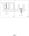
- Figure 2 shows alternative embodiments of elastic support structures formed as optical fibers.
- a fiber 15 is part of a support plate 5 or other support structure. Tissue attached to the fiber 15 exerts a contractile force F to it, e.g. by having an attachment to a part of the well or other support element (not shown). Light I is injected into the fiber, resulting in a moving beam O that can be detected.
- Variant B fiber may be part of the cell culture unit 6, e.g. by protruding through a bottom wall. Contractile force F results in a moving fiber, into which light is injected at I. The moving fiber 15 will similarly result in a moving beam at O.
- Figure 3 shows an exemplary manufacturing method for creating support structures, to be combined with the array of cell culture units.
- the fibers are typically very small and very thin and can be placed at relative short distances, e.g. between 0.1 and 10 mm.
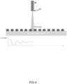
- the fiber length is typically in a range of 0.1 and 0.5 mm, whereas the diameter is even a factor 10-15 smaller, for R/L (see Figure 4 ) ranging between 8 and 15.
- the fiber diameter ranges between 10 and 50 micrometer.
- the fibers 15 are produced by first selectively etching a shielding layer 20 provided on a glass plate, or on a transparent release layer.
- the layer thickness may be anywhere between 1 and 100 micron, so that a pattern of corresponding through holes can be etched.
- the shielding layer is a MoCr layer, but other suitable layers are known to the skilled person. Accordingly, the support plate is provided with a light shielding layer to only allow light through the light fibers.
- a fluid transparent resin is provided on the shielding layer of a suitable thickness corresponding to the fiber length.
- the whole structure (except the shielding layer 20) is optically transparent and the top of the pillars 15 can be made reflective by adding a suitable top layer 22 on the fiber (see Figure D), such that a reflected signal from the top of the pillars can be detected in reflection.
- a collimated light at an angle can lead to better accuracy.
- Another advantage is that with this configuration the light source and the optical readout can be placed on the top or at the bottom of the pillar structure.
- Figure E a cladded fiber is produced, by cladding it with a low - refractive index layer (relative to the fiber core), in order to provide optimal light guiding in the fiber.
- the optical element 15 may include a light shielding element provided in the elastic support structure, so that a light is at least partially shielded by the light shielding element to result in a sensed registration of moving light.
- a refractive optical element may be provided, e.g. a focusing lens of a type described in Henry E. Williams, et al., Fabrication of three-dimensional micro-photonic structures on the tip of optical fibers using SU-8, Optics Express Vol. 19, Issue 23, pp. 22910-22922, (2011 )), see Figure 3 .
- a refractive element 23 can be provided, so that light is refracted to form a light beam directed onto the light sensors. Spot sizes even smaller than a typical pixel size can be obtained; for instance, assuming a spot size of 10 microns, one can easily track the light intensity signal, using an array of light-absorbing (or reflective) material that is patterned on top of an OPD. The linewidth and the spacing of such absorbers can be the same size of the light spot diameter (e.g. 10 microns).
- a thin layer in the order of 100 of nm) can already serve the purpose.
- the optical fiber As the optical fiber is bent due to the force applied force by a tissue (or by a flow), the light spot is moved and partially hits an absorbing pattern as disclosed further below. This effectively modulates the detected intensity, rendering possible to detect small displacements at a very high read-out speed, since only one pixel per device is needed.
- Figure 5 shows exemplary deflection curves for an elastic pillar 15, e.g..of a fiber structure as previously disclosed.
- a hollow-pillar can be realized a reflective layer is intentionally left exposed in the center of the pillar. This can act as a mirror when backlight illumination is used so that light is then reflected back onto the OPD thereby increasing the sensitivity.
- the hollow pillar as a collimator the use of a mirror at one side will make the collimator appear e.g. twice as long increasing the aspect ratio with a factor of 2, depending on the pillar dimensions.
- a similar deflection of the pillar will result in a larger change in signal amplitude.
- F 3 ⁇ ER 4 2 a 2 3 L ⁇ a ⁇
- Suitable pillar materials may be e.g. PDMS, TMMF S2000 & TMMR S2000, or PMMA having Young's moduli ranging between 0.57 - 3.7 MPa (PDMS); between 2.1 -3.8 GPa (TMMF/TMMR); and 2.9 GPa (PMMA).
- a corresponding Force/displacement diagram for different L/R values for the case of 0.57 MPa Young's modulus and for different displacements is shown e.g. a displacement of 20 micron for forces as low as 1E-6 Newton and L/R value of about 20-50 is possible for a PDMS pillar.
- the above calculations relate the displacement to the force exerted on the pillar of different aspect ratio. If forces of 10-6 N are to be measured, one should be able to optically detect displacements of 1 micron, for which aspect ratio of ⁇ 15 are sufficient or alternatively displacements of 10 microns, for which aspect ratio of 30 are required.
- Typical force values range in the order from 10-12 N to 1 N single cells tissues.
- Figure 7 shows a number of support structures having optical elements, wherein a deformation of the elastic support structure results in the light moving over the light sensors in order to register a contractile force of the contractile tissue.
- the whole structure is optically transparent and the top of the pillars is reflective, such that a reflected signal from the top of the pillars can be detected in reflection.
- a collimated light at an angle can lead to better accuracy.
- Another advantage is that with this configuration the light source and the optical readout can be placed on the top or at the bottom of the pillar structure.
- optical reader it is possible, in a non-invasive manner, to perform measurements on biological material, for instance, so that its vitality can be analysed in vitro. It provides high-throughput and parallelized images (e.g. acquisition of complete well-plate with highframe rate) without recurring to bulky instrumentation. It can be integrated to well-plate formats or conceived as a free-standing platform for optical monitoring of micro(bio)mechanical movements. Using light no current/voltages are in direct contact with biological sample, limiting the risk of influencing the measurement. It enables parallel recording/ measuring of micro-mechanical movements from multiple-organs or same interacting with different drugs over long time (days) with high fps.
- the solution can be miniaturized so the well-plate can remain in the incubator (there is no need for off-line measurements, that potentially are disturbing and lower the quality of cell cultures).
- the imaging plate can be customized in design to match a designated measurement setup. For example, by limiting high resolution arrays of photosensitive pixels only close to the center location of the wells in a smart well plate, the total number of pixels within the array can be reduced by a large factor and the frame rate can increase with the same factor since it is determined by the speed of the readout IC and number of lines in the imager.
- the photosensitive pixel area can be made smaller than the pixel pitch. This allows for measurements in reflection mode.
Landscapes
- Health & Medical Sciences (AREA)
- Life Sciences & Earth Sciences (AREA)
- Chemical & Material Sciences (AREA)
- Engineering & Computer Science (AREA)
- Wood Science & Technology (AREA)
- Organic Chemistry (AREA)
- Bioinformatics & Cheminformatics (AREA)
- Zoology (AREA)
- Biomedical Technology (AREA)
- Genetics & Genomics (AREA)
- General Health & Medical Sciences (AREA)
- Sustainable Development (AREA)
- Microbiology (AREA)
- Biochemistry (AREA)
- General Engineering & Computer Science (AREA)
- Biotechnology (AREA)
- Clinical Laboratory Science (AREA)
- Analytical Chemistry (AREA)
- Molecular Biology (AREA)
- Cell Biology (AREA)
- Apparatus Associated With Microorganisms And Enzymes (AREA)
Priority Applications (5)
| Application Number | Priority Date | Filing Date | Title |
|---|---|---|---|
| EP22189456.1A EP4321607A1 (fr) | 2022-08-09 | 2022-08-09 | Dispositifs de lecture optique comprenant des unités de culture cellulaire dans lesquelles un tissu contractile peut être cultivé |
| JP2025507392A JP2025526707A (ja) | 2022-08-09 | 2023-08-08 | 収縮性組織を培養することができる細胞培養ユニットを備える光学読み取りデバイス |
| CN202380057996.7A CN119654400A (zh) | 2022-08-09 | 2023-08-08 | 包括可培养收缩组织的细胞培养单元的光学读取装置 |
| EP23751735.4A EP4569078A1 (fr) | 2022-08-09 | 2023-08-08 | Dispositifs de lecture optique comprenant des unités de culture cellulaire permettant de cultiver des tissus contractiles |
| PCT/NL2023/050420 WO2024035259A1 (fr) | 2022-08-09 | 2023-08-08 | Dispositifs de lecture optique comprenant des unités de culture cellulaire permettant de cultiver des tissus contractiles |
Applications Claiming Priority (1)
| Application Number | Priority Date | Filing Date | Title |
|---|---|---|---|
| EP22189456.1A EP4321607A1 (fr) | 2022-08-09 | 2022-08-09 | Dispositifs de lecture optique comprenant des unités de culture cellulaire dans lesquelles un tissu contractile peut être cultivé |
Publications (1)
| Publication Number | Publication Date |
|---|---|
| EP4321607A1 true EP4321607A1 (fr) | 2024-02-14 |
Family
ID=82851766
Family Applications (2)
| Application Number | Title | Priority Date | Filing Date |
|---|---|---|---|
| EP22189456.1A Withdrawn EP4321607A1 (fr) | 2022-08-09 | 2022-08-09 | Dispositifs de lecture optique comprenant des unités de culture cellulaire dans lesquelles un tissu contractile peut être cultivé |
| EP23751735.4A Pending EP4569078A1 (fr) | 2022-08-09 | 2023-08-08 | Dispositifs de lecture optique comprenant des unités de culture cellulaire permettant de cultiver des tissus contractiles |
Family Applications After (1)
| Application Number | Title | Priority Date | Filing Date |
|---|---|---|---|
| EP23751735.4A Pending EP4569078A1 (fr) | 2022-08-09 | 2023-08-08 | Dispositifs de lecture optique comprenant des unités de culture cellulaire permettant de cultiver des tissus contractiles |
Country Status (4)
| Country | Link |
|---|---|
| EP (2) | EP4321607A1 (fr) |
| JP (1) | JP2025526707A (fr) |
| CN (1) | CN119654400A (fr) |
| WO (1) | WO2024035259A1 (fr) |
Cited By (1)
| Publication number | Priority date | Publication date | Assignee | Title |
|---|---|---|---|---|
| WO2026022367A1 (fr) * | 2024-07-25 | 2026-01-29 | Sophion Bioscience A/S | Système et procédé d'analyse de tissu cellulaire contractile in vitro |
Citations (3)
| Publication number | Priority date | Publication date | Assignee | Title |
|---|---|---|---|---|
| WO2018140497A1 (fr) * | 2017-01-25 | 2018-08-02 | Efimov Igor R | Appareil et procédés pour essais humains précliniques in vitro |
| WO2021158598A1 (fr) * | 2020-02-07 | 2021-08-12 | Tara Biosystems, Inc. | Système intégré pour la culture de tissu en 3d |
| WO2021206551A1 (fr) | 2020-04-09 | 2021-10-14 | River Biomedics B.V. | Dispositif microfluidique pour structure de tissu 3d |
-
2022
- 2022-08-09 EP EP22189456.1A patent/EP4321607A1/fr not_active Withdrawn
-
2023
- 2023-08-08 EP EP23751735.4A patent/EP4569078A1/fr active Pending
- 2023-08-08 CN CN202380057996.7A patent/CN119654400A/zh active Pending
- 2023-08-08 JP JP2025507392A patent/JP2025526707A/ja active Pending
- 2023-08-08 WO PCT/NL2023/050420 patent/WO2024035259A1/fr not_active Ceased
Patent Citations (3)
| Publication number | Priority date | Publication date | Assignee | Title |
|---|---|---|---|---|
| WO2018140497A1 (fr) * | 2017-01-25 | 2018-08-02 | Efimov Igor R | Appareil et procédés pour essais humains précliniques in vitro |
| WO2021158598A1 (fr) * | 2020-02-07 | 2021-08-12 | Tara Biosystems, Inc. | Système intégré pour la culture de tissu en 3d |
| WO2021206551A1 (fr) | 2020-04-09 | 2021-10-14 | River Biomedics B.V. | Dispositif microfluidique pour structure de tissu 3d |
Non-Patent Citations (2)
| Title |
|---|
| HENRY E. WILLIAMS ET AL.: "Fabrication of three-dimensional micro-photonic structures on the tip of optical fibers using SU-8", OPTICS EXPRESS, vol. 19, 2011, pages 22910 - 22922, XP055337463, DOI: 10.1364/OE.19.022910 |
| OSAKI TATSUYA ET AL: "On-chip 3D neuromuscular model for drug screening and precision medicine in neuromuscular disease", NATURE PROTOCOLS, NATURE PUBLISHING GROUP, GB, vol. 15, no. 2, 13 January 2020 (2020-01-13), pages 421 - 449, XP037005236, ISSN: 1754-2189, [retrieved on 20200113], DOI: 10.1038/S41596-019-0248-1 * |
Cited By (1)
| Publication number | Priority date | Publication date | Assignee | Title |
|---|---|---|---|---|
| WO2026022367A1 (fr) * | 2024-07-25 | 2026-01-29 | Sophion Bioscience A/S | Système et procédé d'analyse de tissu cellulaire contractile in vitro |
Also Published As
| Publication number | Publication date |
|---|---|
| JP2025526707A (ja) | 2025-08-15 |
| WO2024035259A1 (fr) | 2024-02-15 |
| EP4569078A1 (fr) | 2025-06-18 |
| CN119654400A (zh) | 2025-03-18 |
Similar Documents
| Publication | Publication Date | Title |
|---|---|---|
| JP4056884B2 (ja) | 作業場所を探触するためのプローブヘッドを有する座標測定装置 | |
| CN102519908B (zh) | 成像式光微流体传感装置及方法 | |
| US10889794B2 (en) | Apparatus for measuring cell activity and method for analyzing cell activity | |
| CN102597841A (zh) | 用于光学仪器的连续、异步自动聚焦的系统和方法 | |
| JP7080222B2 (ja) | 結像機器および測定装置用の微小位置標定方法および装置 | |
| EP4321607A1 (fr) | Dispositifs de lecture optique comprenant des unités de culture cellulaire dans lesquelles un tissu contractile peut être cultivé | |
| Tada et al. | Design of an MR-compatible three-axis force sensor | |
| CN115876759B (zh) | 细胞机械力的检测系统、方法、装置及其制备方法 | |
| GB2337815A (en) | Thickness meter for thin transparent objects | |
| JPH0972843A (ja) | ウェルプレート | |
| EP1703312A1 (fr) | Objectif, analyseur optique, procede de fonctionnement d'un analyseur optique, et microscope | |
| US6121599A (en) | Device for use in the optical investigation of surfaces | |
| CN200989867Y (zh) | 微机型ccd杨氏模量测试仪 | |
| Zhang et al. | Integrated optical diffractive micrograting-based injection force sensor | |
| JP2010223892A (ja) | 電磁界プローブ装置 | |
| CN114739310B (zh) | 一种基于机器视觉的最大拉压应变检测传感器 | |
| US7759631B2 (en) | Raster scanning microscope having transparent optical element with inner curved surface | |
| RU2437058C2 (ru) | Цифровой двухкоординатный динамический автоколлиматор | |
| CN108519176A (zh) | 一种基于线阵ccd的数字差分式张力传感器和利用该传感器的张力检测方法 | |
| JP6109576B2 (ja) | マイクロプレート取り付けシステム及び検出方法 | |
| CN119223790B (zh) | 一种光纤纳米压痕仪及测试方法 | |
| US20240247220A1 (en) | Device for and Use of the Device in Cultivating Tissue and Observing Contractions of the Tissue | |
| US10295463B2 (en) | Device and method for investigating one or a plurality of phase objects | |
| CN114812785B (zh) | 一种用于测试制冷机低温冷头微振动的装置 | |
| JP2000266545A (ja) | 傾斜設定回転レーザー装置 |
Legal Events
| Date | Code | Title | Description |
|---|---|---|---|
| PUAI | Public reference made under article 153(3) epc to a published international application that has entered the european phase |
Free format text: ORIGINAL CODE: 0009012 |
|
| STAA | Information on the status of an ep patent application or granted ep patent |
Free format text: STATUS: THE APPLICATION HAS BEEN PUBLISHED |
|
| AK | Designated contracting states |
Kind code of ref document: A1 Designated state(s): AL AT BE BG CH CY CZ DE DK EE ES FI FR GB GR HR HU IE IS IT LI LT LU LV MC MK MT NL NO PL PT RO RS SE SI SK SM TR |
|
| STAA | Information on the status of an ep patent application or granted ep patent |
Free format text: STATUS: THE APPLICATION IS DEEMED TO BE WITHDRAWN |
|
| 18D | Application deemed to be withdrawn |
Effective date: 20240815 |