EP4321731A2 - Mehrlegierungsturbinenmotorkomponenten und herstellungsverfahren - Google Patents
Mehrlegierungsturbinenmotorkomponenten und herstellungsverfahren Download PDFInfo
- Publication number
- EP4321731A2 EP4321731A2 EP23220151.7A EP23220151A EP4321731A2 EP 4321731 A2 EP4321731 A2 EP 4321731A2 EP 23220151 A EP23220151 A EP 23220151A EP 4321731 A2 EP4321731 A2 EP 4321731A2
- Authority
- EP
- European Patent Office
- Prior art keywords
- alloy
- pieces
- alloys
- blade
- vane
- Prior art date
- Legal status (The legal status is an assumption and is not a legal conclusion. Google has not performed a legal analysis and makes no representation as to the accuracy of the status listed.)
- Pending
Links
Images



Classifications
-
- F—MECHANICAL ENGINEERING; LIGHTING; HEATING; WEAPONS; BLASTING
- F01—MACHINES OR ENGINES IN GENERAL; ENGINE PLANTS IN GENERAL; STEAM ENGINES
- F01D—NON-POSITIVE DISPLACEMENT MACHINES OR ENGINES, e.g. STEAM TURBINES
- F01D5/00—Blades; Blade-carrying members; Heating, heat-insulating, cooling or antivibration means on the blades or the members
- F01D5/12—Blades
- F01D5/14—Form or construction
- F01D5/147—Construction, i.e. structural features, e.g. of weight-saving hollow blades
-
- F—MECHANICAL ENGINEERING; LIGHTING; HEATING; WEAPONS; BLASTING
- F01—MACHINES OR ENGINES IN GENERAL; ENGINE PLANTS IN GENERAL; STEAM ENGINES
- F01D—NON-POSITIVE DISPLACEMENT MACHINES OR ENGINES, e.g. STEAM TURBINES
- F01D5/00—Blades; Blade-carrying members; Heating, heat-insulating, cooling or antivibration means on the blades or the members
- F01D5/12—Blades
- F01D5/14—Form or construction
- F01D5/18—Hollow blades, i.e. blades with cooling or heating channels or cavities; Heating, heat-insulating or cooling means on blades
- F01D5/187—Convection cooling
-
- F—MECHANICAL ENGINEERING; LIGHTING; HEATING; WEAPONS; BLASTING
- F01—MACHINES OR ENGINES IN GENERAL; ENGINE PLANTS IN GENERAL; STEAM ENGINES
- F01D—NON-POSITIVE DISPLACEMENT MACHINES OR ENGINES, e.g. STEAM TURBINES
- F01D5/00—Blades; Blade-carrying members; Heating, heat-insulating, cooling or antivibration means on the blades or the members
- F01D5/12—Blades
- F01D5/28—Selecting particular materials; Particular measures relating thereto; Measures against erosion or corrosion
-
- F—MECHANICAL ENGINEERING; LIGHTING; HEATING; WEAPONS; BLASTING
- F01—MACHINES OR ENGINES IN GENERAL; ENGINE PLANTS IN GENERAL; STEAM ENGINES
- F01D—NON-POSITIVE DISPLACEMENT MACHINES OR ENGINES, e.g. STEAM TURBINES
- F01D5/00—Blades; Blade-carrying members; Heating, heat-insulating, cooling or antivibration means on the blades or the members
- F01D5/12—Blades
- F01D5/28—Selecting particular materials; Particular measures relating thereto; Measures against erosion or corrosion
- F01D5/288—Protective coatings for blades
-
- F—MECHANICAL ENGINEERING; LIGHTING; HEATING; WEAPONS; BLASTING
- F05—INDEXING SCHEMES RELATING TO ENGINES OR PUMPS IN VARIOUS SUBCLASSES OF CLASSES F01-F04
- F05D—INDEXING SCHEME FOR ASPECTS RELATING TO NON-POSITIVE-DISPLACEMENT MACHINES OR ENGINES, GAS-TURBINES OR JET-PROPULSION PLANTS
- F05D2230/00—Manufacture
- F05D2230/20—Manufacture essentially without removing material
- F05D2230/21—Manufacture essentially without removing material by casting
- F05D2230/211—Manufacture essentially without removing material by casting by precision casting, e.g. microfusing or investment casting
-
- F—MECHANICAL ENGINEERING; LIGHTING; HEATING; WEAPONS; BLASTING
- F05—INDEXING SCHEMES RELATING TO ENGINES OR PUMPS IN VARIOUS SUBCLASSES OF CLASSES F01-F04
- F05D—INDEXING SCHEME FOR ASPECTS RELATING TO NON-POSITIVE-DISPLACEMENT MACHINES OR ENGINES, GAS-TURBINES OR JET-PROPULSION PLANTS
- F05D2230/00—Manufacture
- F05D2230/20—Manufacture essentially without removing material
- F05D2230/22—Manufacture essentially without removing material by sintering
-
- F—MECHANICAL ENGINEERING; LIGHTING; HEATING; WEAPONS; BLASTING
- F05—INDEXING SCHEMES RELATING TO ENGINES OR PUMPS IN VARIOUS SUBCLASSES OF CLASSES F01-F04
- F05D—INDEXING SCHEME FOR ASPECTS RELATING TO NON-POSITIVE-DISPLACEMENT MACHINES OR ENGINES, GAS-TURBINES OR JET-PROPULSION PLANTS
- F05D2240/00—Components
- F05D2240/10—Stators
- F05D2240/12—Fluid guiding means, e.g. vanes
- F05D2240/121—Fluid guiding means, e.g. vanes related to the leading edge of a stator vane
-
- F—MECHANICAL ENGINEERING; LIGHTING; HEATING; WEAPONS; BLASTING
- F05—INDEXING SCHEMES RELATING TO ENGINES OR PUMPS IN VARIOUS SUBCLASSES OF CLASSES F01-F04
- F05D—INDEXING SCHEME FOR ASPECTS RELATING TO NON-POSITIVE-DISPLACEMENT MACHINES OR ENGINES, GAS-TURBINES OR JET-PROPULSION PLANTS
- F05D2240/00—Components
- F05D2240/10—Stators
- F05D2240/12—Fluid guiding means, e.g. vanes
- F05D2240/122—Fluid guiding means, e.g. vanes related to the trailing edge of a stator vane
-
- F—MECHANICAL ENGINEERING; LIGHTING; HEATING; WEAPONS; BLASTING
- F05—INDEXING SCHEMES RELATING TO ENGINES OR PUMPS IN VARIOUS SUBCLASSES OF CLASSES F01-F04
- F05D—INDEXING SCHEME FOR ASPECTS RELATING TO NON-POSITIVE-DISPLACEMENT MACHINES OR ENGINES, GAS-TURBINES OR JET-PROPULSION PLANTS
- F05D2240/00—Components
- F05D2240/10—Stators
- F05D2240/12—Fluid guiding means, e.g. vanes
- F05D2240/125—Fluid guiding means, e.g. vanes related to the tip of a stator vane
-
- F—MECHANICAL ENGINEERING; LIGHTING; HEATING; WEAPONS; BLASTING
- F05—INDEXING SCHEMES RELATING TO ENGINES OR PUMPS IN VARIOUS SUBCLASSES OF CLASSES F01-F04
- F05D—INDEXING SCHEME FOR ASPECTS RELATING TO NON-POSITIVE-DISPLACEMENT MACHINES OR ENGINES, GAS-TURBINES OR JET-PROPULSION PLANTS
- F05D2240/00—Components
- F05D2240/20—Rotors
- F05D2240/30—Characteristics of rotor blades, i.e. of any element transforming dynamic fluid energy to or from rotational energy and being attached to a rotor
- F05D2240/303—Characteristics of rotor blades, i.e. of any element transforming dynamic fluid energy to or from rotational energy and being attached to a rotor related to the leading edge of a rotor blade
-
- F—MECHANICAL ENGINEERING; LIGHTING; HEATING; WEAPONS; BLASTING
- F05—INDEXING SCHEMES RELATING TO ENGINES OR PUMPS IN VARIOUS SUBCLASSES OF CLASSES F01-F04
- F05D—INDEXING SCHEME FOR ASPECTS RELATING TO NON-POSITIVE-DISPLACEMENT MACHINES OR ENGINES, GAS-TURBINES OR JET-PROPULSION PLANTS
- F05D2240/00—Components
- F05D2240/20—Rotors
- F05D2240/30—Characteristics of rotor blades, i.e. of any element transforming dynamic fluid energy to or from rotational energy and being attached to a rotor
- F05D2240/304—Characteristics of rotor blades, i.e. of any element transforming dynamic fluid energy to or from rotational energy and being attached to a rotor related to the trailing edge of a rotor blade
-
- F—MECHANICAL ENGINEERING; LIGHTING; HEATING; WEAPONS; BLASTING
- F05—INDEXING SCHEMES RELATING TO ENGINES OR PUMPS IN VARIOUS SUBCLASSES OF CLASSES F01-F04
- F05D—INDEXING SCHEME FOR ASPECTS RELATING TO NON-POSITIVE-DISPLACEMENT MACHINES OR ENGINES, GAS-TURBINES OR JET-PROPULSION PLANTS
- F05D2240/00—Components
- F05D2240/20—Rotors
- F05D2240/30—Characteristics of rotor blades, i.e. of any element transforming dynamic fluid energy to or from rotational energy and being attached to a rotor
- F05D2240/307—Characteristics of rotor blades, i.e. of any element transforming dynamic fluid energy to or from rotational energy and being attached to a rotor related to the tip of a rotor blade
-
- F—MECHANICAL ENGINEERING; LIGHTING; HEATING; WEAPONS; BLASTING
- F05—INDEXING SCHEMES RELATING TO ENGINES OR PUMPS IN VARIOUS SUBCLASSES OF CLASSES F01-F04
- F05D—INDEXING SCHEME FOR ASPECTS RELATING TO NON-POSITIVE-DISPLACEMENT MACHINES OR ENGINES, GAS-TURBINES OR JET-PROPULSION PLANTS
- F05D2240/00—Components
- F05D2240/80—Platforms for stationary or moving blades
-
- F—MECHANICAL ENGINEERING; LIGHTING; HEATING; WEAPONS; BLASTING
- F05—INDEXING SCHEMES RELATING TO ENGINES OR PUMPS IN VARIOUS SUBCLASSES OF CLASSES F01-F04
- F05D—INDEXING SCHEME FOR ASPECTS RELATING TO NON-POSITIVE-DISPLACEMENT MACHINES OR ENGINES, GAS-TURBINES OR JET-PROPULSION PLANTS
- F05D2300/00—Materials; Properties thereof
- F05D2300/10—Metals, alloys or intermetallic compounds
- F05D2300/17—Alloys
-
- F—MECHANICAL ENGINEERING; LIGHTING; HEATING; WEAPONS; BLASTING
- F05—INDEXING SCHEMES RELATING TO ENGINES OR PUMPS IN VARIOUS SUBCLASSES OF CLASSES F01-F04
- F05D—INDEXING SCHEME FOR ASPECTS RELATING TO NON-POSITIVE-DISPLACEMENT MACHINES OR ENGINES, GAS-TURBINES OR JET-PROPULSION PLANTS
- F05D2300/00—Materials; Properties thereof
- F05D2300/10—Metals, alloys or intermetallic compounds
- F05D2300/17—Alloys
- F05D2300/173—Aluminium alloys, e.g. AlCuMgPb
-
- Y—GENERAL TAGGING OF NEW TECHNOLOGICAL DEVELOPMENTS; GENERAL TAGGING OF CROSS-SECTIONAL TECHNOLOGIES SPANNING OVER SEVERAL SECTIONS OF THE IPC; TECHNICAL SUBJECTS COVERED BY FORMER USPC CROSS-REFERENCE ART COLLECTIONS [XRACs] AND DIGESTS
- Y02—TECHNOLOGIES OR APPLICATIONS FOR MITIGATION OR ADAPTATION AGAINST CLIMATE CHANGE
- Y02T—CLIMATE CHANGE MITIGATION TECHNOLOGIES RELATED TO TRANSPORTATION
- Y02T50/00—Aeronautics or air transport
- Y02T50/60—Efficient propulsion technologies, e.g. for aircraft
Definitions
- the disclosure relates to gas turbine engine blade and vane manufacture. More particularly, the disclosure relates to multi-material blades and vanes.
- Gas turbine engines (used in propulsion and power applications and broadly inclusive of turbojets, turboprops, turbofans, turboshafts, industrial gas turbines, and the like) include blades and vanes (collectively airfoil members).
- multi-material blades have been proposed. Examples include bi- and tri-cast blades and blades formed of separately manufactured sections welded or otherwise bonded to each other.
- United States Patent Application Publication No. 2014/0294652A1 discloses direct metal fabrication of component greenbodies followed by assembly and sintering.
- United States Patent 7,141,812 (the ⁇ 812 patent) of Appleby et al., November 28, 2006 , "Devices, methods, and systems involving castings”
- United States Patent 10,207,315 (the ⁇ 315 patent) of Appleby et al., February 19, 2019 , "Systems, devices, and/or methods for manufacturing castings” disclose casting methods using laminated tooling to form direct or indirect molds. Such a method is known under the trademark TOMO TM of Mikro Systems, Inc. of Charlottesville, Virginia. Individual laminations may be produced lithographically and assembled/secured. ".
- FAST field assisted sintering technology
- an article being a blade or a vane comprising: an airfoil having an inner diameter (ID) end and an outer diameter (OD) end and having a suction side and a pressure side and a leading edge and a trailing edge; and an inner platform and/or attachment root at the ID end and/or an outer platform at the OD end.
- At least one of the inner platform, root, and/or outer platform comprises one or more pieces of a first alloy.
- One or more pieces of a second alloy form a leading edge section of the airfoil.
- One or more pieces of a third alloy form a trailing edge section of the airfoil.
- One or more pieces of a fourth alloy form a spar of the airfoil between the leading edge section and trailing edge section and extending into said at least one of the inner platform, root, and/or outer platform.
- a further embodiment of any of the foregoing embodiments may additionally and/or alternatively include the article being a blade.
- the OD end may be a shrouded tip or a free (unshrouded) tip.
- a further embodiment of any of the foregoing embodiments may additionally and/or alternatively include the article being a vane.
- the ID end may be at an ID platform or may be or a free (unshrouded) end.
- a blade comprising: an airfoil extending to a tip; an attachment root; and a platform between the attachment root and the tip.
- the platform comprises one or more pieces of a first alloy.
- One or more pieces of a second alloy form a leading edge section of the airfoil.
- One or more pieces of a third alloy form a trailing edge section of the airfoil.
- One or more pieces of a fourth alloy form a spar of the airfoil between the leading edge section and trailing edge section and extending into the attachment root.
- One or more pieces of a fifth alloy forms a tip section of the airfoil.
- one or more pieces of a sixth alloy form an outer portion of the root.
- the sixth alloy is higher strength than the second, third, fourth, and fifth alloys.
- the first alloy and sixth alloy are the same.
- the one or more pieces of the first alloy are a respective suction side piece and pressure side piece; and/or the one or more pieces of the sixth alloy are a forward suction side piece, a forward pressure side piece, an aft suction side piece, and an aft pressure side piece.
- the fifth alloy is less dense than the first, second, third and fourth alloys; and/or the fifth alloy is has lower strength and creep resistance than the first, second, third and fourth alloys.
- the fourth alloy is more creep resistant than the second and third alloys.
- one or more pieces of a liner alloy form a lining of passageways in the spar, the liner alloy being more corrosion resistant than the fourth alloy.
- the second alloy and third alloy are NiAl.
- the spar spans from the pressure side to the suction side.
- a cooling passageway system has trunks in the spar and extends into the leading edge section, trailing edge section and tip section.
- cooling passageway system trunks are partially in the spar and partially in one or more adjacent root pieces.
- pin and socket joints span one or more mating pairs of the pieces.
- rail and groove joints span one or more mating pairs of the pieces.
- a further embodiment of any of the foregoing embodiments may additionally and/or alternatively include a method for manufacturing the blade.
- the method comprises: metal injection molding (MIM) of one or more of the pieces; and sintering an assembly of the pieces.
- MIM metal injection molding
- a further embodiment of any of the foregoing embodiments may additionally and/or alternatively include the method further comprising: forming a mold for the MIM using a laminate intermediary.
- the forming a mold for the MIM comprises: forming the laminate intermediary as a first positive of the associated piece or portion thereof; forming a first negative from the laminate intermediary; forming a second positive from the negative; and forming a MIM mold or portion thereof from the second positive.
- the sintering comprises: heating the assembly of the pieces; applying a load across the assembly of the pieces; and applying current across the assembly of the pieces to fuse the pieces.
- a vane comprising: an airfoil having an inner diameter (ID) end and an outer diameter (OD) end and having a suction side and a pressure side and a leading edge and a trailing edge; and an inner platform at the ID end and an outer platform at the OD end.
- the inner platform comprises one or more pieces of a first alloy.
- One or more pieces of a second alloy form a leading edge section of the airfoil.
- One or more pieces of a third alloy form a trailing edge section of the airfoil,
- One or more pieces of a fourth alloy form a spar of the airfoil between the leading edge section and trailing edge section.
- the outer platform comprises one or more pieces of a fifth alloy.
- the first and fifth alloys are the same.
- the first and fifth alloys are higher strength than the second and third alloys; the first and fifth alloys are less oxidation resistant than the second and third alloys; the first and fifth alloys are lighter than the fourth alloy; and/or the first and fifth alloys are less creep resistant than the fourth alloy.
- the fourth alloy is more creep resistant and/or less oxidation resistant than the second and third alloys.
- FIG. 1 shows a blade 20 comprising a metallic substrate (e.g., nickel-based superalloy) and optionally one or more coatings (not shown - e.g., ceramic thermal barrier coatings environmental barrier coatings, bondcoats thereunder, and the like).
- the blade and substrate have an airfoil 24, an attachment root 26, and optionally a platform 28 at a blade-root junction.
- the attachment root 26 e.g., firtree or dovetail
- the attachment root 26 has: an inner diameter (ID) end 30 (relative to the centerline of the engine and disk (not shown) in which the blade mounts; an outer diameter end 32 at an underside 34 of the platform; a forward end 36; and aft end 38 ( FIG. 2 ); a first lateral side 40 ( FIG. 7 ); and a second lateral side 42 ( FIG. 1 ).
- the airfoil 24 ( FIG. 1 ) has: an inner diameter (ID) proximal end 50 at the platform outer diameter (OD) gaspath surface 52; a tip 54; a leading edge 56; a trailing edge 58; a suction side 60 ( FIG. 2 ); and a pressure side 62 ( FIG. 1 ).
- the blade has an internal cooling passageway system 900 (schematically shown in flattened form in FIG. 3 ) extending from one or more inlets 902, 904, 906 along the root 26 ID surface 30 to one or more outlets (e.g., along the airfoil surface, tip, and/or gaspath surface of the platform such as a trailing edge slot outlet 910 (including tip flag outlet 912) and leading edge cooling holes).
- an internal cooling passageway system 900 (schematically shown in flattened form in FIG. 3 ) extending from one or more inlets 902, 904, 906 along the root 26 ID surface 30 to one or more outlets (e.g., along the airfoil surface, tip, and/or gaspath surface of the platform such as a trailing edge slot outlet 910 (including tip flag outlet 912) and leading edge cooling holes).
- the blade may represent any of numerous known or yet-developed configurations in terms of general shape and passageway configuration.
- the blade 20 is formed in multiple sections/members/pieces of different alloys. Depending on the implementation a given section/member may be one or more pieces. Examples illustrated generally split members into multiple pieces. Surface boundaries between sections of different alloys are shown in solid line in FIG. 1 . Within cross-sections ( FIGs. 4-7 ) boundaries between the original pieces (even of a given alloy) are shown in broken lines within the cross-sectioning of the fused assembly and projecting across gaps.
- An exemplary first section/member 100 (root member - FIG. 1 ) forms most of an external contour of the root 26 (e.g., forms the firtree or dovetail).
- the root member 100 may also form the platform 28 or a peripheral portion thereof.
- the root/platform member 100 has multiple peripheral pieces (four shown in FIG. 7 as 100A, 100B, 100C, 100D). Generally these form respectively front pieces 100A,B ( FIG. 7 ) of the root on the two circumferential sides and aft pieces 100C,D of the root on the two circumferential sides.
- the respective front pieces and aft pieces may be separated by two pieces of the platform on central portions of the respective two circumferential sides (one being to the suction side of the airfoil and one being to the pressure side).
- a second section/member 102 ( FIG. 4 ) (leading edge (LE) member) forms an airfoil leading edge along a major portion of a span S of the airfoil (e.g., in excess of 50% of the span S, more particularly, in excess of 90% and, in an example, 90-97%).
- the example has two pieces 102A, 102B generally to the two circumferential sides and generally one to the suction side and one to the pressure side.
- a third section/member 104 ( FIG. 4 ) (trailing edge (TE) member) forms a trailing edge portion of the airfoil of a similar local span fraction to that of the second section/member 102.
- the example has two pieces 104A, 104B generally to the two circumferential sides and generally one to the suction side and one to the pressure side.
- a fourth section/member 108 ( FIG. 8 ) (tip member) forms a tip cap of the airfoil accounting for the remaining airfoil span.
- the illustrated example is a single piece extending from leading edge to trailing edge and suction side to pressure side.
- a fifth section/member 110 ( FIG. 4 ) (spar member) form a spar that extends along the airfoil between the LE member 102 and TE member 104 but also extends radially inward through the platform into the attachment root).
- the example has two pieces 110A, 110B generally to the two circumferential sides and generally one to the suction side and one to the pressure side.
- Materials and manufacturing techniques for the various sections/pieces may be tailored to provide advantageous performance and for advantageous manufacturability.
- the LE piece(s) 102 alloy may be selected for oxidation performance over the spar piece(s) 110 alloy.
- the TE piece(s) 104 alloy may be selected for oxidation and lower density than the spar piece(s) 110 alloy.
- the tip piece 108 alloy may be selected for light weight and environmental resistance.
- the spar piece(s) 110 alloy may be selected for creep resistance because the spar will bear centrifugal loading. Oxidation and environmental resistance may of lower concern for the spar due to its protection/encapsulation from the high temperature environment, the spar potentially being exposed to only two internal flows of cooling air. However, where internal corrosion is a concern, the spar may have a lining (discussed below).
- the root piece(s) 100 alloy may be selected for high strength due to high stress along attachment surfaces in addition to increased fatigue requirements associated with acceleration and deceleration of the engine. Its relative inboard position puts slightly less of premium on lightweight and its relative isolation from high forced gas exposure reduces any premium on oxidation and environmental resistance. To the extent that the root alloy extends along the platform, typically the platform may be under less aerodynamic loading than the airfoil.
- the exemplary spar pieces extend well into the root (e.g., all the way through shown but preferably at least halfway through the span of the firtree), the LE and TE pieces do not. In the exemplary embodiment they extend to inner diameter (ID) ends mating with the outer diameter (OD) surface of the piece(s) forming the platform.
- ID inner diameter
- OD outer diameter
- subassemblies which may or may not coincide with members or sections
- assembly physical contacting of the members
- securing bonding, sintering, and the like
- the various pieces may be formed (e.g., molded) with mating surfaces (e.g., generally flat for convenience) having mating registry features (e.g., moieties such as tongue(rail)/groove or pin/socket combinations) for mating and registering with other pieces of the associated member and/or other of the members.
- the TOMO TM process may form a laminate positive of the piece used to directly or indirectly cast tooling.
- the laminate positive serves as a mandrel to cast/mold an elastomeric (e.g., polyurethane or other polymeric material) negative.
- the elastomeric negative is used to cast/mold a ceramic positive (e.g., of alumina, silica and/or other slurry).
- the ceramic positive is used to cast the MIM mold tooling.
- a low level of sintering within an individual piece may occur as part of a debinding process after the MIM.
- One or more further levels of sintering may occur in assembly of pieces or subassemblies to sinter pieces or subassemblies to each other.
- FAST field assisted sintering technology
- Additional variations have one or more linings (not shown) formed of an alloy offering greater corrosion resistance than the alloy of the lined pieces.
- this liner alloy can be created by producing thin, conforming sheet through MIM processing using TOMO TM derived tools, followed by debinding and assembly to the required member subassembly. Final sintering of the overall assembly may also sinter the lining to the associated members.
- the lining may be applied as a coating or deposition onto the internal surfaces (e.g., by PVD processing).
- the lining may be comprised of an MCrAlY coating or a ceramic barrier coating, such as Al 2 O 3 , TiAlN, AlTiN, or combinations thereof, to specifically address ingested particulate that is corrosive to turbine alloys in more austere operating environments.
- This coating/deposit may be applied prior to the final joining of the two mating surfaces (e.g., mating surfaces of the spar pieces 110A, 110B).
- the protective coating may be applied by PVD methods such as cathodic arc or reactive chemical methods such as CVD.
- Exemplary coating thickness is 2.5 to 25.0 micrometers, more particularly 2.5 to 13.0 micrometers.
- the mating surfaces adjacent may be masked prior to application to target only the desired surfaces.
- Alternative linings such as those discussed above formed via MIM may be thicker and may be preformed or formed other than by coating techniques.
- candidates for such deposited liners are materials already used for corrosion resistant bondcoats. Typically, these would be rich in Cr and Al.
- Such high Cr, Al overlay alloys are disclosed in United States Patent 4,419,416, Gupta et al., December 6, 1983 , "Overlay coatings for superalloys".
- Oxidation resistance may be measured by exposing a sample to a static isothermal or cyclic furnace exposure in an oxidizing environment. The rate of oxidation is measured as weight change vs. hours of exposure (grams/hour).
- Creep resistance may be measured by/as change in length at a static load with time. Commonly described as time to 0.2% plastic deformation. ASTM E139-11(2018), Standard Test Methods for Conducting Creep, Creep-Rupture, and Stress-Rupture Tests of Metallic Materials, ASTM International, West Conshohocken, PA, 2018.
- Strength may be measured by/as the load required to plastically or elastically deform the alloy. Commonly described as 0.2% yield stress. Test method analysis of behavior as per ASTM E21-17e1, Standard Test Methods for Elevated Temperature Tension Tests of Metallic Materials, ASTM International, West Conshohocken, PA, 2017.
- Environmental resistance may be measured by/as weight change when exposed to a corrosive sulfate-bearing medium at an elevated temperature (g/hour). Alternatively corrosion may be described as a rate of pit depth formation with time ( ⁇ m/hour).
- Table I lists compositions of particular alloys. These are from single examples of nominal published data. Normal commercial compositional variations and impurity levels are expected. The identification of a particular element for one alloy does not preclude that element being present at impurity levels in another alloy even if those impurity levels are higher than in the former.
- Patent 2,570,193 Ni(bal)-Cr(12.5)-Mo(4.2)-Al(6.1)-Ti(0.8)-C(0.12)-B(0.012)-Zr(0.10)-Cb+Ta(2.2) 7.913 B-1900+Hf Ni(bal)-Cr(8)-Co(10)-C(0.11)-Ti(1)-Al(6)-Mo(6)-B(0.015)-Hf(1.15)-Ta(4.25)-Zr(0.08) 8.19 TMS-238 Ni(bal)-Co(6.5)-Cr(5.8)-Mo(1.1)-Re(6.4)-Ru(5)-W(4)-Al(5.9)- Ta(7.6)-Nb(0.1) 9.0 EPM-102 Ni(bal)-Cr(2.0)-Al(5.55)-Ta(8.25)-W(6.0)-Mo(2.0)-Re(5.95)-Ru(3.0)-Co(16.5)-C(0.03)-Hf(0.15) 9.20 TABLE II
- Candidate methods include casting, metal injection molding (MIM), and field assisted sintering technology (FAST).
- Lithographic/laminate techniques e.g., TOMO TM may be used in intermediate stages of pattern or mold manufacture.
- the alloys for the exemplary MIM/FAST technique can be produced through several methods.
- One area is gas atomization techniques, but may also include rotary atomization, and plasma rotating electrode process (PREP).
- Atomized powders may then be subsequently screened to an appropriate mesh size to produce the final component.
- One such mesh size is 325 mesh or 44 ⁇ m and finer particle size.
- the screened powders may then be mixed with a suitable binder or carrier for the respective manufacturing process.
- the TOMO TM process for MIM tooling manufacture can produce center line parted tooling such that the seam of the sections may traverse mid span from the leading to the trailing edge.
- the TOMO TM process allows for the major details to be produced in a single half of the tool while the mating surface can be simplified to facilitate mating features to join the two halves together.
- two evenly split halves are required to produce tooling and the inclusion of joining features such as dovetail or pin joints may require multiple inserts or slides.
- Exemplary manufacture technique for the root/platform section/piece(s) 100A-F is MIM.
- the injection molding of alloy powder into the respective cavities may produce: respective portions of an internal platform/root cavity to accept the mating portion of the spar; and respective portions of the external geometries of the root/platform including attachment/mounting features for mating with the blade disk.
- Exemplary initial/precursor root attachment features may either be either of a trapezoid that may be fully machined during final processing to provide the fir tree or other shape or a near net shaped fir tree or other profile that may reduce the overall machining required.
- the root pieces forming the attachment may also form the platform 28.
- the tip piece(s) 108 may similarly be manufactured of an environmentally resistant alloy. Although a single tip piece is shown, there may be a similar two-piece parting as with the LE and TE members.
- FIG. 8 also shows pins 140 and sockets 142. Protruding pin portions may be received in complementary sockets of the associated two pieces. Or the pin may be formed unitarily with one of the mating pieces. Tongue (rail) 146 and groove 148 joints are shown in FIG. 7 .
- the spar pieces may be similarly manufactured.
- a highly creep resistant alloy is desirable to maximize the peak load carrying capability of the airfoil at high temperatures.
- the TOMO TM MIM process is desirable due to the complex parting line and internal feature geometries.
- the two halves of the spar may be formed with the internal cooling features and with external mating features. Such features facilitate attachment to the root sections and to the adjacent leading and trailing edges. More conventional non-TOMO TM MIM may be used for the other members.
- An exemplary manufacturing technique for the LE piece 102 is TOMO TM MIM or non-TOMO TM MIM.
- the simpler, repeating internal shape of the LE lends itself to non-TOMO TM MIM or other process with a simpler parting line configuration and conventional tooling practices.
- the LE piece(s) 102 may be formed using a light weight, oxidation resistant powder such as a nickel aluminide (e.g., NiAl, CAS number 12003-78-0 ).
- An exemplary manufacturing technique for the TE piece 104 is by TOMO TM MIM tooling and sintering processes.
- the trailing edge of an airfoil typically has a complex configuration of both internal heat transfer geometries and fine features and geometries to meter air out of the trailing edge discharge.
- This portion of the airfoil may also be made from a light weight, oxidation resistant alloy such as nickel aluminide (NiAl).
- An exemplary assembly sequence and technique includes assembly of the pieces of each individual member to each other in the green state. After that subassembly process the resulting subassembly may be debound by heating in an inert (e.g., noble gas) or reducing (e.g., H 2 , CO, and the like or combinations) atmosphere.
- the subassemblies need not correspond exactly to the respective members or groups of members.
- a given member may be formed from portions previously subassembled in separate subassemblies. There also may be sequential subassembly steps before debinding.
- the MIM pieces Prior to assembling, the MIM pieces may be cleaned (e.g., surface-cleaning solvent such as isopropyl alcohol or acetone).
- the spar pieces may be assembled to each other.
- the leading edge member pieces may similarly be assembled to each other as may be the and trailing edge member pieces.
- Each of these exemplary members is individually assembled and debound.
- the tip member may similarly be debound.
- the individual root and platform pieces may be cleaned and debound.
- the assembly is heated to a suitably high temperature to facilitate diffusion and necking of adjacent particles. With sufficient time, the porosity in the structure may be reduced through grain growth and particle coalescence during sintering.
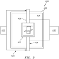
- the sintering /joining can be completed using either conventional sintering or the FAST process (FAST apparatus 400 schematically shown in FIG. 9 ). Temperature for joining the segments may be sufficiently high to allow for diffusion, but not high enough to cause incipient melting of the structure.
- FIG. 9 shows a chamber 402 having an interior 404. The assembly is held in tooling 410 which may be coupled to a pressure source 420.
- the exemplary pressure source comprises a hydraulic pressure source 422 (e.g., pump) coupled to rams 424, 426 engaging respective portions of the tooling.
- the apparatus 400 further comprises a current source such as a high current power supply 430 coupled to the tooling to apply current across the assembly.
- hot isostatic pressing can be utilized post-sintering to close up any internal porosity that was not closed during the sintering of the individual members/subassemblies (if any, either in the debinding or a separate sintering prior to the final assembly sintering) or that may otherwise exist along the parting lines of the adjacent pieces/members/subassemblies. This may be performed on the raw post-FAST or conventionally sintered assembly before machining.
- the assembly may then undergo directional re-crystallization by passing the assembly through a float zone furnace to control the direction of grain growth without melting the alloys. This can be accomplished using a traditional Bridgman style float zone furnace that is resistance or induction heated. This heats the completed assembly to sufficiently high temperatures to allow for the diffusion and re-ordering of the structure.
- a float zone furnace that is resistance or induction heated. This heats the completed assembly to sufficiently high temperatures to allow for the diffusion and re-ordering of the structure.
- either no starter block or a cast columnar starter block may be used as a seed to facilitate crystal orientation. If a single crystal article is desired, a helical shaped starter block or a seed of known orientation can be utilized to convert the final article into a single crystal.
- Processing of the material may be conducted at temperatures above 2000°F (1093°C), but below the liquidus of the alloy ⁇ 2450°F (1343°C). In cases where it is not desirable to have the entire airfoil single crystal, the refining process can be stopped at the root section to allow the root section to remain polycrystalline.
- the article may undergo traditional alloy processing to optimize performance.
- the system may be solution heat treated at a sufficiently high temperature to allow for diffusion of species, but not high enough to cause incipient melting. This may be followed by secondary and aging heat treatments to optimize the gamma prime stricture within the alloy. As required, the heat treatment process can be modified to accommodate the application of external metallic and ceramic coatings as required by the end use application.
- a vane 300 (singlet ( FIG. 10 ) or cluster) may also be produced using conventional MIM and TOMO TM MIM techniques.
- the inner and outer platforms (ID platform 302 and OD shroud 304) of the vane may be produced by MIM using conventional tooling.
- An exemplary alloy for these structures may be PWA 1480 or LDS 1101. These segments (or segment pieces) may then be debound in an inert atmosphere.
- the main airfoil 310 segment(s) in one example may be produced out of three sections/members 320, 322, 324.
- the main spar 324 may be produced out of an alloy with creep resistance such as PWA 1484. As with the blade example, this main spar may, for example, be assembled from two pieces respectively along the suction and pressure side of the airfoil. These pieces may be produced utilizing tooling produced the TOMO TM process to accommodate the complexity of the internal cooling passages into the die and follow MIM processing to produce debound sections.
- the leading and trailing edge members 322, 324 may be similar to those of the exemplary blades.
- first, second, and the like in the following claims is for differentiation within the claim only and does not necessarily indicate relative or absolute importance or temporal order. Similarly, the identification in a claim of one element as “first” (or the like) does not preclude such "first” element from identifying an element that is referred to as “second” (or the like) in another claim or in the description.
Landscapes
- Engineering & Computer Science (AREA)
- Mechanical Engineering (AREA)
- General Engineering & Computer Science (AREA)
- Chemical & Material Sciences (AREA)
- Materials Engineering (AREA)
- Architecture (AREA)
- Turbine Rotor Nozzle Sealing (AREA)
Applications Claiming Priority (3)
| Application Number | Priority Date | Filing Date | Title |
|---|---|---|---|
| US202062958228P | 2020-01-07 | 2020-01-07 | |
| US17/143,669 US12146419B1 (en) | 2020-01-07 | 2021-01-07 | Multi-alloy turbine engine components and manufacture methods |
| EP21151030.0A EP3848555B1 (de) | 2020-01-07 | 2021-01-11 | Turbinentriebwerkskomponenten aus mehreren legierungen und herstellungsverfahren |
Related Parent Applications (1)
| Application Number | Title | Priority Date | Filing Date |
|---|---|---|---|
| EP21151030.0A Division EP3848555B1 (de) | 2020-01-07 | 2021-01-11 | Turbinentriebwerkskomponenten aus mehreren legierungen und herstellungsverfahren |
Publications (2)
| Publication Number | Publication Date |
|---|---|
| EP4321731A2 true EP4321731A2 (de) | 2024-02-14 |
| EP4321731A3 EP4321731A3 (de) | 2024-04-24 |
Family
ID=74130151
Family Applications (2)
| Application Number | Title | Priority Date | Filing Date |
|---|---|---|---|
| EP23220151.7A Pending EP4321731A3 (de) | 2020-01-07 | 2021-01-11 | Mehrlegierungsturbinenmotorkomponenten und herstellungsverfahren |
| EP21151030.0A Active EP3848555B1 (de) | 2020-01-07 | 2021-01-11 | Turbinentriebwerkskomponenten aus mehreren legierungen und herstellungsverfahren |
Family Applications After (1)
| Application Number | Title | Priority Date | Filing Date |
|---|---|---|---|
| EP21151030.0A Active EP3848555B1 (de) | 2020-01-07 | 2021-01-11 | Turbinentriebwerkskomponenten aus mehreren legierungen und herstellungsverfahren |
Country Status (2)
| Country | Link |
|---|---|
| US (1) | US12146419B1 (de) |
| EP (2) | EP4321731A3 (de) |
Cited By (1)
| Publication number | Priority date | Publication date | Assignee | Title |
|---|---|---|---|---|
| EP4606994A1 (de) * | 2024-02-20 | 2025-08-27 | RTX Corporation | Kombinierter schaufelspitzenfahnenkern für eine gasturbinentriebwerksschaufel |
Families Citing this family (7)
| Publication number | Priority date | Publication date | Assignee | Title |
|---|---|---|---|---|
| DE102020133998A1 (de) * | 2020-12-17 | 2022-06-23 | Rolls-Royce Deutschland Ltd & Co Kg | Schaufelbauteil, Verfahren zu dessen Herstellung und Gasturbine |
| DE102020216193A1 (de) * | 2020-12-17 | 2022-08-11 | Rolls-Royce Deutschland Ltd & Co Kg | Schaufelbauteil, Verfahren zu dessen Herstellung und Gasturbine |
| EP4105450A1 (de) | 2021-06-18 | 2022-12-21 | Raytheon Technologies Corporation | Passives spielkontrollsystem, hergestellt durch feldunterstützte sintertechnologie (fast) |
| US12055056B2 (en) | 2021-06-18 | 2024-08-06 | Rtx Corporation | Hybrid superalloy article and method of manufacture thereof |
| EP4105449A1 (de) | 2021-06-18 | 2022-12-21 | Raytheon Technologies Corporation | Hybride verbundene konfiguration für eine äussere schaufelluftdichtung (boas) |
| EP4105438B1 (de) * | 2021-06-18 | 2026-04-08 | RTX Corporation | Klebeverfahren für die reparatur eines gasturbinentriebwerk-bauteils |
| EP4105444A1 (de) * | 2021-06-18 | 2022-12-21 | Raytheon Technologies Corporation | Verbinden einzelner turbinenleitschaufeln mit feldunterstützter sintertechnik (fast) |
Citations (6)
| Publication number | Priority date | Publication date | Assignee | Title |
|---|---|---|---|---|
| US4419416A (en) | 1981-08-05 | 1983-12-06 | United Technologies Corporation | Overlay coatings for superalloys |
| US7141812B2 (en) | 2002-06-05 | 2006-11-28 | Mikro Systems, Inc. | Devices, methods, and systems involving castings |
| US20140294652A1 (en) | 2008-01-23 | 2014-10-02 | Mikro Systems, Inc. | Method of Making a Combustion Turbine Component from Metallic Combustion Turbine Subcomponent Greenbodies |
| US9687910B2 (en) | 2012-12-14 | 2017-06-27 | United Technologies Corporation | Multi-shot casting |
| US10207315B2 (en) | 2008-09-26 | 2019-02-19 | United Technologies Corporation | Systems, devices, and/or methods for manufacturing castings |
| US10287896B2 (en) | 2013-09-17 | 2019-05-14 | United Technologies Corporation | Turbine blades and manufacture methods |
Family Cites Families (30)
| Publication number | Priority date | Publication date | Assignee | Title |
|---|---|---|---|---|
| US2848192A (en) * | 1953-03-12 | 1958-08-19 | Gen Motors Corp | Multi-piece hollow turbine bucket |
| US4314794A (en) * | 1979-10-25 | 1982-02-09 | Westinghouse Electric Corp. | Transpiration cooled blade for a gas turbine engine |
| US20030063993A1 (en) | 2001-10-03 | 2003-04-03 | Reiter Frederick B. | Metal injection molding multiple dissimilar materials to form composite electric machine rotor and rotor sense parts |
| JP2003222026A (ja) | 2002-01-30 | 2003-08-08 | Hitachi Ltd | タービン翼の製作方法およびタービン翼 |
| US6889419B2 (en) | 2002-04-16 | 2005-05-10 | Delphi Technologies, Inc. | Method of making a composite electric machine component of a desired magnetic pattern |
| US7241416B2 (en) | 2003-08-12 | 2007-07-10 | Borg Warner Inc. | Metal injection molded turbine rotor and metal injection molded shaft connection attachment thereto |
| US7648336B2 (en) * | 2006-01-03 | 2010-01-19 | General Electric Company | Apparatus and method for assembling a gas turbine stator |
| US7780410B2 (en) * | 2006-12-27 | 2010-08-24 | General Electric Company | Method and apparatus for gas turbine engines |
| US20080237403A1 (en) | 2007-03-26 | 2008-10-02 | General Electric Company | Metal injection molding process for bimetallic applications and airfoil |
| DE102007027465A1 (de) * | 2007-06-14 | 2008-12-18 | Rolls-Royce Deutschland Ltd & Co Kg | Gasturbinenschaufel mit modularem Aufbau |
| US8267662B2 (en) | 2007-12-13 | 2012-09-18 | General Electric Company | Monolithic and bi-metallic turbine blade dampers and method of manufacture |
| US8142163B1 (en) * | 2008-02-01 | 2012-03-27 | Florida Turbine Technologies, Inc. | Turbine blade with spar and shell |
| US8033790B2 (en) * | 2008-09-26 | 2011-10-11 | Siemens Energy, Inc. | Multiple piece turbine engine airfoil with a structural spar |
| US8511999B1 (en) * | 2009-03-31 | 2013-08-20 | Florida Turbine Technologies, Inc. | Multiple piece turbine rotor blade |
| US8678771B2 (en) | 2009-12-14 | 2014-03-25 | Siemens Energy, Inc. | Process for manufacturing a component |
| US8496443B2 (en) * | 2009-12-15 | 2013-07-30 | Siemens Energy, Inc. | Modular turbine airfoil and platform assembly with independent root teeth |
| US9394795B1 (en) * | 2010-02-16 | 2016-07-19 | J & S Design Llc | Multiple piece turbine rotor blade |
| US8813812B2 (en) | 2010-02-25 | 2014-08-26 | Siemens Energy, Inc. | Turbine component casting core with high resolution region |
| US8444389B1 (en) | 2010-03-30 | 2013-05-21 | Florida Turbine Technologies, Inc. | Multiple piece turbine rotor blade |
| DE102011089260A1 (de) | 2011-12-20 | 2013-06-20 | Rolls-Royce Deutschland Ltd & Co Kg | Verfahren zur Herstellung eines Bauteils durch Metallpulverspritzgießen |
| EP3055091A4 (de) | 2013-10-09 | 2017-07-05 | United Technologies Corporation | Turbinenkomponente mit mehreren dichten und eigenschaften |
| WO2015058043A1 (en) * | 2013-10-18 | 2015-04-23 | United Technologies Corporation | Multiple piece engine component |
| US20170022821A1 (en) * | 2013-11-25 | 2017-01-26 | General Electric Technology Gmbh | Blade assembly for a turbomachine on the basis of a modular structure |
| DE102014206827A1 (de) | 2014-04-09 | 2015-10-15 | Siemens Aktiengesellschaft | Verfahren zum Fügen und Gasturbinenkomponente |
| US9387533B1 (en) | 2014-09-29 | 2016-07-12 | Mikro Systems, Inc. | Systems, devices, and methods involving precision component castings |
| US10494933B2 (en) | 2016-03-18 | 2019-12-03 | General Electric Company | Airfoil with multi-material reinforcement |
| US10422228B2 (en) | 2016-04-12 | 2019-09-24 | United Technologies Corporation | Manufacturing a monolithic component with discrete portions formed of different metals |
| US10815798B2 (en) * | 2018-02-08 | 2020-10-27 | General Electric Company | Turbine engine blade with leading edge strip |
| EP3533897A1 (de) | 2018-02-28 | 2019-09-04 | Siemens Aktiengesellschaft | Verbesserungen im zusammenhang mit metalllegierungskomponenten und deren herstellung |
| US11466576B2 (en) | 2019-11-04 | 2022-10-11 | Raytheon Technologies Corporation | Airfoil with continuous stiffness joint |
-
2021
- 2021-01-07 US US17/143,669 patent/US12146419B1/en active Active
- 2021-01-11 EP EP23220151.7A patent/EP4321731A3/de active Pending
- 2021-01-11 EP EP21151030.0A patent/EP3848555B1/de active Active
Patent Citations (6)
| Publication number | Priority date | Publication date | Assignee | Title |
|---|---|---|---|---|
| US4419416A (en) | 1981-08-05 | 1983-12-06 | United Technologies Corporation | Overlay coatings for superalloys |
| US7141812B2 (en) | 2002-06-05 | 2006-11-28 | Mikro Systems, Inc. | Devices, methods, and systems involving castings |
| US20140294652A1 (en) | 2008-01-23 | 2014-10-02 | Mikro Systems, Inc. | Method of Making a Combustion Turbine Component from Metallic Combustion Turbine Subcomponent Greenbodies |
| US10207315B2 (en) | 2008-09-26 | 2019-02-19 | United Technologies Corporation | Systems, devices, and/or methods for manufacturing castings |
| US9687910B2 (en) | 2012-12-14 | 2017-06-27 | United Technologies Corporation | Multi-shot casting |
| US10287896B2 (en) | 2013-09-17 | 2019-05-14 | United Technologies Corporation | Turbine blades and manufacture methods |
Non-Patent Citations (1)
| Title |
|---|
| no. 12003-78-0 |
Cited By (2)
| Publication number | Priority date | Publication date | Assignee | Title |
|---|---|---|---|---|
| EP4606994A1 (de) * | 2024-02-20 | 2025-08-27 | RTX Corporation | Kombinierter schaufelspitzenfahnenkern für eine gasturbinentriebwerksschaufel |
| US12553350B2 (en) | 2024-02-20 | 2026-02-17 | Rtx Corporation | Combined tip flag blade core |
Also Published As
| Publication number | Publication date |
|---|---|
| EP3848555A1 (de) | 2021-07-14 |
| EP4321731A3 (de) | 2024-04-24 |
| US12146419B1 (en) | 2024-11-19 |
| EP3848555B1 (de) | 2023-12-27 |
Similar Documents
| Publication | Publication Date | Title |
|---|---|---|
| EP3848555B1 (de) | Turbinentriebwerkskomponenten aus mehreren legierungen und herstellungsverfahren | |
| EP1354656B1 (de) | Verfahren zum Vorbereiten von gebauten Gasturbinenmotorbauteilen | |
| US8528208B2 (en) | Methods of fabricating a coated component using multiple types of fillers | |
| US9938834B2 (en) | Bladed gas turbine engine rotors having deposited transition rings and methods for the manufacture thereof | |
| CN102536465B (zh) | 使用短效涂层制作构件的方法 | |
| US9266170B2 (en) | Multi-material turbine components | |
| EP1837104B1 (de) | Instandhaltung von Hochdruckturbinenplatten mit gesinterten Vorformen | |
| EP1978208B1 (de) | Verfahren zur Herstellung von Turbinenrotoren aus mehreren Legierungen mit integrierten Schaufeln | |
| EP1656233B1 (de) | Verfahren zur herstellung und/oder reparatur von bauteilen für gasturbinen | |
| US6969240B2 (en) | Integral turbine composed of a cast single crystal blade ring diffusion bonded to a high strength disk | |
| DE102011056346A1 (de) | Verfahren zur Herstellung einer Komponente mit einer zweischichtigen Strukturbeschichtung | |
| US10408083B2 (en) | Hollow metal objects and methods for making same | |
| US20060239825A1 (en) | Bi-cast blade ring for multi-alloy turbine rotor | |
| US10801338B1 (en) | Apparatus and process of forming an integrally bladed rotor with cooled single crystal blades and an equiax nickel disk | |
| US10793943B2 (en) | Method of producing a gas turbine engine component | |
| EP3231534A2 (de) | Herstellung einer monolithischen komponente mit diskreten, aus unterschiedlichen metallen geformten abschnitten | |
| US10294804B2 (en) | Dual alloy gas turbine engine rotors and methods for the manufacture thereof | |
| EP1728971A1 (de) | Einstückige Turbine bestehend aus einem gegossenen Einkristallschaufelring diffusionsverbunden mit einer hochfesten Scheibe | |
| Lund | The aging alloys have matured | |
| CA1217073A (en) | Plasma spray-cast components |
Legal Events
| Date | Code | Title | Description |
|---|---|---|---|
| PUAI | Public reference made under article 153(3) epc to a published international application that has entered the european phase |
Free format text: ORIGINAL CODE: 0009012 |
|
| STAA | Information on the status of an ep patent application or granted ep patent |
Free format text: STATUS: THE APPLICATION HAS BEEN PUBLISHED |
|
| AC | Divisional application: reference to earlier application |
Ref document number: 3848555 Country of ref document: EP Kind code of ref document: P |
|
| AK | Designated contracting states |
Kind code of ref document: A2 Designated state(s): AL AT BE BG CH CY CZ DE DK EE ES FI FR GB GR HR HU IE IS IT LI LT LU LV MC MK MT NL NO PL PT RO RS SE SI SK SM TR |
|
| REG | Reference to a national code |
Ref country code: DE Ref legal event code: R079 Free format text: PREVIOUS MAIN CLASS: F01D0005280000 Ipc: F01D0005140000 |
|
| PUAL | Search report despatched |
Free format text: ORIGINAL CODE: 0009013 |
|
| AK | Designated contracting states |
Kind code of ref document: A3 Designated state(s): AL AT BE BG CH CY CZ DE DK EE ES FI FR GB GR HR HU IE IS IT LI LT LU LV MC MK MT NL NO PL PT RO RS SE SI SK SM TR |
|
| RIC1 | Information provided on ipc code assigned before grant |
Ipc: F01D 5/28 20060101ALI20240319BHEP Ipc: F01D 5/14 20060101AFI20240319BHEP |
|
| STAA | Information on the status of an ep patent application or granted ep patent |
Free format text: STATUS: REQUEST FOR EXAMINATION WAS MADE |
|
| 17P | Request for examination filed |
Effective date: 20241024 |
|
| RBV | Designated contracting states (corrected) |
Designated state(s): AL AT BE BG CH CY CZ DE DK EE ES FI FR GB GR HR HU IE IS IT LI LT LU LV MC MK MT NL NO PL PT RO RS SE SI SK SM TR |
|
| GRAP | Despatch of communication of intention to grant a patent |
Free format text: ORIGINAL CODE: EPIDOSNIGR1 |
|
| STAA | Information on the status of an ep patent application or granted ep patent |
Free format text: STATUS: GRANT OF PATENT IS INTENDED |
|
| INTG | Intention to grant announced |
Effective date: 20250620 |
|
| GRAJ | Information related to disapproval of communication of intention to grant by the applicant or resumption of examination proceedings by the epo deleted |
Free format text: ORIGINAL CODE: EPIDOSDIGR1 |
|
| STAA | Information on the status of an ep patent application or granted ep patent |
Free format text: STATUS: REQUEST FOR EXAMINATION WAS MADE |
|
| INTC | Intention to grant announced (deleted) | ||
| GRAP | Despatch of communication of intention to grant a patent |
Free format text: ORIGINAL CODE: EPIDOSNIGR1 |
|
| STAA | Information on the status of an ep patent application or granted ep patent |
Free format text: STATUS: GRANT OF PATENT IS INTENDED |