EP4321802A1 - Brûleur à gaz - Google Patents
Brûleur à gaz Download PDFInfo
- Publication number
- EP4321802A1 EP4321802A1 EP22832863.9A EP22832863A EP4321802A1 EP 4321802 A1 EP4321802 A1 EP 4321802A1 EP 22832863 A EP22832863 A EP 22832863A EP 4321802 A1 EP4321802 A1 EP 4321802A1
- Authority
- EP
- European Patent Office
- Prior art keywords
- gas
- degrees
- gas burner
- ejection angle
- sub
- Prior art date
- Legal status (The legal status is an assumption and is not a legal conclusion. Google has not performed a legal analysis and makes no representation as to the accuracy of the status listed.)
- Pending
Links
Images



Classifications
-
- F—MECHANICAL ENGINEERING; LIGHTING; HEATING; WEAPONS; BLASTING
- F23—COMBUSTION APPARATUS; COMBUSTION PROCESSES
- F23D—BURNERS
- F23D14/00—Burners for combustion of a gas, e.g. of a gas stored under pressure as a liquid
- F23D14/20—Non-premix gas burners, i.e. in which gaseous fuel is mixed with combustion air on arrival at the combustion zone
- F23D14/22—Non-premix gas burners, i.e. in which gaseous fuel is mixed with combustion air on arrival at the combustion zone with separate air and gas feed ducts, e.g. with ducts running parallel or crossing each other
- F23D14/24—Non-premix gas burners, i.e. in which gaseous fuel is mixed with combustion air on arrival at the combustion zone with separate air and gas feed ducts, e.g. with ducts running parallel or crossing each other at least one of the fluids being submitted to a swirling motion
-
- F—MECHANICAL ENGINEERING; LIGHTING; HEATING; WEAPONS; BLASTING
- F23—COMBUSTION APPARATUS; COMBUSTION PROCESSES
- F23D—BURNERS
- F23D17/00—Burners for combustion simultaneously or alternately of gaseous or liquid or pulverulent fuel
- F23D17/002—Burners for combustion simultaneously or alternately of gaseous or liquid or pulverulent fuel gaseous or liquid fuel
-
- F—MECHANICAL ENGINEERING; LIGHTING; HEATING; WEAPONS; BLASTING
- F23—COMBUSTION APPARATUS; COMBUSTION PROCESSES
- F23C—METHODS OR APPARATUS FOR COMBUSTION USING FLUID FUEL OR SOLID FUEL SUSPENDED IN A CARRIER GAS OR AIR
- F23C99/00—Subject-matter not provided for in other groups of this subclass
-
- F—MECHANICAL ENGINEERING; LIGHTING; HEATING; WEAPONS; BLASTING
- F23—COMBUSTION APPARATUS; COMBUSTION PROCESSES
- F23D—BURNERS
- F23D14/00—Burners for combustion of a gas, e.g. of a gas stored under pressure as a liquid
- F23D14/46—Details
- F23D14/48—Nozzles
-
- F—MECHANICAL ENGINEERING; LIGHTING; HEATING; WEAPONS; BLASTING
- F23—COMBUSTION APPARATUS; COMBUSTION PROCESSES
- F23D—BURNERS
- F23D14/00—Burners for combustion of a gas, e.g. of a gas stored under pressure as a liquid
- F23D14/46—Details
- F23D14/48—Nozzles
- F23D14/58—Nozzles characterised by the shape or arrangement of the outlet or outlets from the nozzle, e.g. of annular configuration
-
- F—MECHANICAL ENGINEERING; LIGHTING; HEATING; WEAPONS; BLASTING
- F23—COMBUSTION APPARATUS; COMBUSTION PROCESSES
- F23C—METHODS OR APPARATUS FOR COMBUSTION USING FLUID FUEL OR SOLID FUEL SUSPENDED IN A CARRIER GAS OR AIR
- F23C2900/00—Special features of, or arrangements for combustion apparatus using fluid fuels or solid fuels suspended in air; Combustion processes therefor
- F23C2900/9901—Combustion process using hydrogen, hydrogen peroxide water or brown gas as fuel
-
- F—MECHANICAL ENGINEERING; LIGHTING; HEATING; WEAPONS; BLASTING
- F23—COMBUSTION APPARATUS; COMBUSTION PROCESSES
- F23D—BURNERS
- F23D2900/00—Special features of, or arrangements for burners using fluid fuels or solid fuels suspended in a carrier gas
- F23D2900/14—Special features of gas burners
- F23D2900/14003—Special features of gas burners with more than one nozzle
Definitions
- the present disclosure relates to a gas burner such as a gas-fired boiler.
- Patent Document 1 discloses a gas burner provided with, in a tip portion of a gas nozzle, a main hole for injecting a gas at an injection angle of 35° to 45° with respect to a central axis of the gas burner and a sub hole for injecting the gas at an injection angle of 45° to 55° with respect to the central axis of the gas burner.
- Patent Document 1 JP4600850B
- Patent Document 1 shows an example of 13A city gas (a gas containing methane as a principal component, and also containing ethane, propane, and butane as other components) as the type of gas fuel, Patent Document 1 does not indicate a gas fuel pressure.
- a pressure of gas fuel for example, a boiler burner fueled by city gas or LPG (liquefied petroleum gas) is applied with a pressure at a maximum of about 130 KPa, and even when hydrogen is used as fuel, a maximum pressure is about 80 KPa.
- LPG liquefied petroleum gas
- the present disclosure has been made in view of the above-described problems, and the object of the present disclosure is to provide a gas burner capable of suppressing combustion oscillation as well as suppressing the generation of NOx by increasing a pressure of gas fuel and setting an ejection angle of the gas fuel in a predetermined range.
- a gas burner including: a nozzle where gas fuel flows; and a primary air supply part for supplying, from around the nozzle, primary air whose air ratio to the gas fuel is less than 1.
- the nozzle includes: at least one main hole configured to eject the gas fuel at an ejection angle of not less than 25 degrees and not greater than 45 degrees with respect to a central axis of the gas burner; and at least one sub hole configured to eject the gas fuel at an ejection angle of not less than 35 degrees and not greater than 55 degrees with respect to the central axis of the gas burner, the ejection angle of the sub hole being greater than the ejection angle of the main hole.
- the gas fuel flowing in the nozzle has a gas pressure of not less than 300 kPa.
- combustion oscillation can be suppressed as well as generation of NOx can be suppressed by increasing a pressure of gas fuel and further setting ejection angles of the gas fuel from a main hole and a sub hole in predetermined ranges.
- FIG. 1 is a schematic side cross-sectional view showing a partial cross section of a gas burner 1 according to one embodiment of the present disclosure.
- the gas burner 1 is disposed in a burner throat part 5 on a side wall of a furnace 3.
- the gas burner 1 has a triple structure of a gas nozzle 7 disposed in a central axis C portion of the gas burner 1, a primary air flow passage (primary air supply part) 9 for introducing combustion air to an outer peripheral portion of the gas nozzle 7, and a secondary air flow passage 11 disposed in an outer peripheral portion of the primary air flow passage 9.
- the gas nozzle 7 and the primary air flow passage 9 are disposed inside a cylindrical primary sleeve 13, and the secondary air flow passage 11 is formed inside a cylindrical secondary sleeve 15 disposed on an outer peripheral side of the primary sleeve 13.
- the gas fuel is structured to be ejected into the furnace 3 from a main hole 25 and a sub hole 27 formed in the tip portion of the gas nozzle 7.
- a tertiary air flow passage (not shown) may be disposed in an outer peripheral portion of the secondary air flow passage 11.
- primary air F1 which is central air flowing in from an opening part 21 forming an inlet and flowing through the primary air flow passage 9, is a straight flow
- a swirling force is given to part of the primary air F1 by a swirler (flame holder) 17 disposed in an outlet section of the gas nozzle 7, that is, an outlet section of the primary air flow passage 9, a stagnant region 19 is formed in a region in the furnace 3 on a wake side of the swirler 17, and the gas fuel is taken into the stagnant region 19, making it possible to stably holding flame.
- an air register 23 is installed in an inlet section of the secondary air flow passage 11, and an air register type swirling device gives a swirling force to secondary air F2 flowing into the secondary air flow passage 11.
- a water tube 6 is installed so as to surround the opening portion in order to cool the periphery of the opening portion.
- the air ratio of the primary air F1 to the gas fuel ejected from the gas nozzle 7 is lower than the air ratio of the secondary air F2 to the gas fuel ejected from the gas nozzle 7, and further, the primary air F 1 supplied from the primary air flow passage 9 is set such that the air ratio to the ejected gas fuel is less than 1.
- the air ratio is the ratio of the amount of air when the amount of air required to completely burn the gas fuel is set to 1.
- main holes 25 and four sub holes 27 are disposed in the tip portion of the gas nozzle 7. It is configured such that the gas fuel flowing through all the main holes is 80% to 90% of the total gas fuel flow and the gas fuel flowing through all the sub holes is 20% to 10% of the total gas fuel flow. That is, the sub hole 27 is formed with a smaller hole diameter than the main hole 25 and a ratio A1:A2 is between 80:20 and 90: 10, where A1 is a total opening area of the plurality of main holes 25 and A2 is a total opening area of the plurality of sub holes 27.
- the fuel ejected from the sub holes 27 is easily taken into the stagnant region 19 formed on the wake side of the swirler 17 for giving the swirling force to part of the primary air, thereby stably holding flame and making it possible to suppresses combustion oscillation.
- the swirler 17 for giving the swirling force to part of the primary air may be burned out if the fuel exceeding 20% is ejected from the sub holes 27. Therefore, it is preferably configured such that the gas fuel flowing through all the sub holes flows 20% to 10% of the total gas fuel flow.
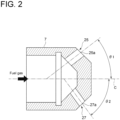
- the plurality of (four) main holes 25 in the tip portion of the gas nozzle 7 are disposed around the central axis C of the gas nozzle 7 (which is also the central axis C of the gas burner 1) symmetrically with the central axis C therebetween, and are disposed so as to have an ejection angle of 50 degrees to 90 degrees with the central axis C of the gas nozzle 7 therebetween (an elevation angle of 25 degrees to 45 degrees with respect to the central axis C).
- the elevation angle of the main hole 25 with respect to the central axis C is referred to as a main hole ejection angle ⁇ 1.
- the plurality of (four) sub holes 27 are disposed around the central axis C of the gas nozzle 7 symmetrically with the central axis C therebetween, and are disposed so as to have an ejection angle of 70 degrees to 110 degrees with the central axis C of the gas nozzle 7 therebetween (an elevation angle of 35 degrees to 55 degrees with respect to the central axis C).
- the ejection angle of the sub hole 27 is configured to eject the gas fuel at an ejection angle greater than the ejection angle of the main hole 25.
- the elevation angle of the sub hole 27 with respect to the central axis C is referred to as a sub hole ejection angle ⁇ 2.
- the sub hole ejection angle ⁇ 2 is configured to eject the gas fuel at an ejection angle greater than the main hole ejection angle.
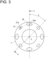
- the four main holes 25 and the four sub holes 27 are alternately and evenly disposed around the central axis C. That is, the main holes 25 and the sub holes 27 are disposed around the central axis C with an equal pitch angle ⁇ of 45 degrees. Since the plurality of main holes 25 are thus formed in the tip portion of the gas nozzle 7 so as to be disposed around the central axis C symmetrically with each other with the central axis C therebetween, the gas fuel ejected from the main holes 25 is evenly ejected without any bias with respect to the center of the gas burner 1.
- the plurality of sub holes 27 are also formed in the tip portion of the gas nozzle 7 so as to be disposed around the central axis C symmetrically with each other with the central axis C therebetween, the gas fuel ejected from the sub holes 27 is evenly ejected without any bias with respect to the center of the gas burner 1.
- a center position 25a of the opening of the main hole 25 and a center position 27a of the opening of the sub hole 27 are disposed such that a distance from the central axis C of the gas nozzle 7 is the same.
- the main hole 25 and the sub hole 27 have circular cross-sectional shapes.
- An inlet valve 31 is provided, at an outlet of a gas tank 29 where gas fuel is stored, to control supply and shutoff of the gas fuel from the gas tank 29, and a pressure reducing valve 33 is provided, on an outlet side of the inlet valve 31, to reduce the pressure to a predetermined pressure.
- a flow rate meter 35 Downstream of the pressure reducing valve 33, a flow rate meter 35, a thermometer 37, a shutoff valve 39, a pressure gauge 41, a flow control valve 43, a shutoff valve 45, a burner inlet pressure gauge 47, and a burner inlet valve 49 are disposed in order as shown in FIG. 1 .
- Gas fuel is supplied to the gas nozzle 7 of the gas burner 1 by opening the burner inlet valve 49.
- the pressure of the gas fuel ejected from the main hole 25 and the sub hole 27 is a gas pressure of the gas fuel flowing in the gas nozzle 7 and is a pressure at the inlet of the gas burner 1, and is measured by the burner inlet pressure gauge 47.
- High-pressure gas fuel exceeding 300 kPa is pressurized and stored in the gas tank 29, and is supplied to the gas burner 1 after being depressurized, by the pressure reducing valve 33 etc., to a target gas pressure of not less than 300 kPa to be used.
- combustion oscillation can be suppressed as well as generation of NOx can be suppressed by increasing the gas pressure of the gas fuel to not less than 300 kPa and further setting the ejection angles of the gas fuel from the main hole 25 and the sub hole 27 in the predetermined ranges.
- the air ratio is lowered, the temperature in the region where the fuel burns is lowered and generation of NOx is suppressed.
- the gas pressure of the gas fuel flowing in the gas nozzle 7 is set at not less than 300 kPa, mixing of the gas fuel and primary air with the air ratio of less than 1 is promoted, and the proportion of the gas fuel burning in the low-temperature region relatively increases. Whereby, it is possible to suppress generation of NOx.
- the gas burner 1 (gas nozzle 7) has the main hole 25 with the ejection angle of not less than 25 degrees and not greater than 45 degrees with respect to the central axis C of the gas burner 1 and the sub hole 27 with the ejection angle of not less than 35 degrees and not greater than 55 degrees with respect to the central axis C of the gas burner 1.
- the generation amount of NOx can be reduced by setting the sub hole ejection angle ⁇ 2 to less than 55 degrees. If the sub hole ejection angle ⁇ 2 exceeds 55 degrees, flame retention near the swirler 17 becomes too strong, increasing the burnout potential of the swirler 17 as well as causing concern about the increase in NOx. If the sub hole ejection angle ⁇ 2 is less than 35 degrees, the flame retention effect becomes weak and the oscillation potential increases. Therefore, combustion oscillation can be suppressed as well as the generation amount of NOx can be reduced by setting the sub hole ejection angle ⁇ 2 to not less than 35 degrees and not greater than 55 degrees.
- gas fuel is a compressible fluid, and has the property of expanding in the axial direction and the radial direction at once in the outlet section of the gas nozzle 7 as the gas fuel is increased in pressure. Therefore, even if the ejection angle is narrowed as the influence of the pressure, the narrowed angle is effective in ensuring flame retention by the sub hole 27 and avoiding the adverse effect on long flame by the main hole 25. Therefore, combustion oscillation can be suppressed as well as the generation amount of NOx can be reduced, even if the ejection angle is narrowed by reducing the elevation lower limit angle of the ejection angle disclosed in the conventional art (Patent Document 1).
- the gas fuel is gas fuel containing hydrogen
- the main hole ejection angle ⁇ 1 of the main hole 25 is not less than 25 degrees and not greater than 35 degrees
- the sub hole ejection angle ⁇ 2 of the sub hole 27 is not less than 35 degrees and not greater than 45 degrees.
- the "gas fuel containing hydrogen” includes gas fuel containing hydrogen and other fuel (mixed combustion) and gas fuel containing only hydrogen (single combustion), and even the gas fuel containing hydrogen and other fuel can further be classified into fuel containing hydrogen as a principal component (the volume fraction of hydrogen is at least 50%) and fuel containing other fuel as a principal component (the volume fraction of hydrogen is less than 50%).
- the "gas fuel containing hydrogen” includes all of these cases.
- the gas tank 29 is a hydrogen gas tank 129 in which gas fuel containing hydrogen is stored
- the gas burner 1 is a hydrogen gas burner 101 for ejecting and burning gas fuel containing hydrogen.
- the other configurations of the gas fuel supply system are the same as in one embodiment shown in FIG. 1 .
- the structure of the hydrogen gas burner 101 is the same as that shown in FIGs. 1 to 3 .
- Gas fuel containing hydrogen at a high pressure exceeding 300 kPa (for example, 15 MPa) is pressurized and stored in the hydrogen gas tank 129, and is supplied to the hydrogen gas burner 101 after being depressurized, by the pressure reducing valve 33 etc., to the target gas pressure of not less than 300 kPa to be used.
- 300 kPa for example, 15 MPa
- a booster 53 is applied in order to increase the pressure to the target gas pressure of not less than 300 kPa to be used and the by-product hydrogen 51 is supplied to the hydrogen gas burner 101.
- FIG. 4 shows a relationship graph of a test result showing a relationship between NOx and an inlet pressure of the hydrogen gas burner 101 for gas fuel containing hydrogen (an ejection pressure from the main hole 25 and the sub hole 27).
- Test conditions are as shown in Table 1.
- Table 1 Test condition Fuel type Hydrogen single combustion Fuel amount 95m3N/h Total air ratio 1.1 Air ratio of primary air/secondary air 30/70
- the test checked the inlet pressure of the hydrogen gas burner 101 for four conditions of 80 KPa (comparison base), 300 KPa, 500 KPa, and 900 KPa.
- the change in ejection pressure was tested by changing the hole diameters of the main hole 25 and the sub hole 27 formed in the tip portion of the gas nozzle 7 while keeping the fuel amount constant, without changing the structure of the hydrogen gas burner 101.
- the hole diameters were changed as shown in Table 2.
- the ejection angles of the main hole 25 and the sub hole 27 during the combustion test are 40° for the main hole ejection angle ⁇ 1 and 45° for the sub hole ejection angle ⁇ 2.
- a boiler burner fueled by city gas, LPG, or the like is applied at a maximum of about 130 KPa, and even when hydrogen is used as fuel, a maximum pressure is about 80 KPa, and thus 80 KPa was used as the base for comparison.
- NOx was reduced at 300 KPa, 500 KPa, and 900 KPa.
- 900 KPa showed a NOx reduction effect of about 30%. Therefore, not less than 300 KPa at which the NOx reduction effect was seen was set as a setting pressure for the increased pressure. It is more desirable to set the pressure at not less than 500 KPa.
- the trend of the test result showing the relationship between NOx and the inlet pressure of the hydrogen gas burner 101 (the ejection pressure from the main hole 25 and the sub hole 27) is considered to be equal in the gas fuel such as city gas or LPG other than the gas fuel containing hydrogen.
- the gas fuel such as city gas or LPG other than the gas fuel containing hydrogen.
- LPG relative to base NOx at the ejection pressure of 70 KPa, the NOx reductions of about 20% at 300 KPa and about 25% at 500 KPa were confirmed. Therefore, not less than 300 KPa at which the NOx reduction effect was seen was set as the setting pressure for the increased pressure. It is more desirable to set the pressure at not less than 500 KPa.
- the appropriate range for the sub hole ejection angle ⁇ 2 is between 35 degrees and 45 degrees.
- the combustion oscillation can be suppressed as well as the generation amount of NOx can further be reduced by increasing the ejection pressure of the gas fuel containing hydrogen to not less than 300 KPa, as well as by setting the ejection angle from the main hole 25 between 25 degrees and 35 degrees and by setting the ejection angle from the sub hole 27 to not less than 35 degrees to and not greater than 45 degrees.
- the nozzle since the gas pressure of the gas fuel is increased to not less than 300 kPa, and further, the nozzle includes the main hole with the ejection angle of not less than 25 degrees and not greater than 45 degrees with respect to the central axis of the gas burner and the sub hole with the ejection angle of not less than 35 degrees and not greater than 55 degrees with respect to the central axis of the gas burner, it is possible to suppress combustion oscillation, as well as it is possible to suppress generation of NOx.
- the air ratio is lowered, the temperature in the region where the fuel burns is lowered and generation of NOx is suppressed.
- the configuration (1) since the gas pressure of the gas fuel flowing in the nozzle is set at not less than 300 kPa, mixing of the gas fuel and primary air with the air ratio of less than 1 is promoted, and the proportion of the gas fuel burning in the low-temperature region relatively increases. Whereby, it is possible to suppress generation of NOx.
- the nozzle has the main hole with the ejection angle of not less than 25 degrees and not greater than 45 degrees with respect to the central axis of the gas burner and the sub hole with the ejection angle of not less than 35 degrees and not greater than 55 degrees with respect to the central axis of the gas burner.
- Slow combustion due to long flame of flame can be promoted by setting the ejection angle of the gas fuel from the main hole (elevation angle with respect to the central axis of the gas burner) to less than 45 degrees. If the ejection angle of the main hole exceeds 45 degrees, the potential for combustion oscillation due to pressure fluctuations in the furnace increases.
- the ejection angle of the main hole is less than 25 degrees, the long flame becomes excessive and affects the heat absorption characteristics of the boiler. Therefore, since both stabilization and long flame of flame can be achieved by setting the ejection angle of the main hole to not less than 25 degrees and not greater than 45 degrees, it is possible to suppress combustion oscillation as well as it is possible to achieve the reduction in NOx by decreasing the flame temperature with the slow combustion due to the long flame.
- the generation amount of NOx can be reduced by setting the ejection angle of the sub hole to less than 55 degrees. If the ejection angle of sub hole exceeds 55 degrees, the balance of flame retention near the burner is lost and the oscillation potential increases. If the ejection angle of sub hole is less than 35 degrees, the flame retention effect becomes weak and the oscillation potential increases. Therefore, combustion oscillation can be suppressed as well as the generation amount of NOx can be reduced by setting the ejection angle of the sub hole to not less than 35 degrees and not greater than 55 degrees.
- the gas burner according to another aspect is the gas burner as defined in (1), wherein the gas fuel contains hydrogen.
- the gas burner according to still another aspect is the gas burner as defined in (2), wherein the ejection angle of the main hole is not less than 25 degrees and not greater than 35 degrees, and the ejection angle of the sub hole is not less than 35 degrees and not greater than 45 degrees.
- the sub hole since hydrogen has the high combustion speed and superior combustibility compared to city gas or LPG, the potential for combustion oscillation can be reduced compared to the case of the fuel such as city gas or LPG. Therefore, there is no problem with the influence on combustion oscillation even if the ejection angle from the sub hole of the configuration (1) is narrowed from the range of 35° to 55° to the range of 35° to 45°, and it is possible to suppress combustion oscillation as well as it is possible to achieve the reduction in NOx by decreasing the flame temperature with the slow combustion due to the long flame.
- the gas burner according to yet another aspect is the gas burner as defined in any of (1) to (3), wherein the at least one main hole includes a plurality of main holes formed in a tip portion of the nozzle such that the plurality of main holes are disposed around the central axis of the gas burner symmetrically with each other with the central axis of the gas burner therebetween.
- the gas fuel containing hydrogen ejected from the main holes can evenly be ejected without any bias with respect to the center of the gas burner, making it possible to address, without delay, slow combustion due to long flame.
- the gas burner according to yet another aspect is the gas burner as defined in any of (1) to (4), wherein the at least one sub hole includes a plurality of sub holes formed in a tip portion of the nozzle such that the plurality of sub holes are disposed around the central axis of the gas burner symmetrically with each other with the central axis of the gas burner therebetween.
- the gas fuel containing hydrogen ejected from the sub holes can evenly be ejected without any bias with respect to the center of the gas burner, making it possible to evenly form the flame retention region around the swirler (flame holder) and to reduce the potential for combustion oscillation.
- the gas burner according to yet another aspect is the gas burner as defined in any of (1) to (5), wherein a ratio A1 :A2 is between 80:20 and 90: 10, where A1 is a total opening area of a plurality of the main holes and A2 is a total opening area of a plurality of the sub holes.
Landscapes
- Engineering & Computer Science (AREA)
- Chemical & Material Sciences (AREA)
- Combustion & Propulsion (AREA)
- Mechanical Engineering (AREA)
- General Engineering & Computer Science (AREA)
- Pre-Mixing And Non-Premixing Gas Burner (AREA)
- Gas Burners (AREA)
- Glass Compositions (AREA)
- Gas Separation By Absorption (AREA)
Applications Claiming Priority (2)
| Application Number | Priority Date | Filing Date | Title |
|---|---|---|---|
| JP2021106750A JP7248744B2 (ja) | 2021-06-28 | 2021-06-28 | ガスバーナ、及びガス焚きボイラ |
| PCT/JP2022/024271 WO2023276713A1 (fr) | 2021-06-28 | 2022-06-17 | Brûleur à gaz |
Publications (2)
| Publication Number | Publication Date |
|---|---|
| EP4321802A1 true EP4321802A1 (fr) | 2024-02-14 |
| EP4321802A4 EP4321802A4 (fr) | 2024-10-09 |
Family
ID=84692333
Family Applications (1)
| Application Number | Title | Priority Date | Filing Date |
|---|---|---|---|
| EP22832863.9A Pending EP4321802A4 (fr) | 2021-06-28 | 2022-06-17 | Brûleur à gaz |
Country Status (7)
| Country | Link |
|---|---|
| US (1) | US20240280260A1 (fr) |
| EP (1) | EP4321802A4 (fr) |
| JP (1) | JP7248744B2 (fr) |
| KR (1) | KR102881266B1 (fr) |
| AU (1) | AU2022303921B2 (fr) |
| WO (1) | WO2023276713A1 (fr) |
| ZA (1) | ZA202311284B (fr) |
Families Citing this family (3)
| Publication number | Priority date | Publication date | Assignee | Title |
|---|---|---|---|---|
| JP2020146300A (ja) * | 2019-03-14 | 2020-09-17 | 株式会社三洋物産 | 遊技機 |
| US12590556B1 (en) * | 2024-10-01 | 2026-03-31 | General Electric Company | Gas turbine engine, fuel nozzle assembly, and method |
| JP7825813B1 (ja) * | 2025-08-18 | 2026-03-09 | 双日マシナリー株式会社 | アンモニア燃焼壁バーナ |
Family Cites Families (19)
| Publication number | Priority date | Publication date | Assignee | Title |
|---|---|---|---|---|
| JPS51148828A (en) * | 1975-06-16 | 1976-12-21 | Mitsui Eng & Shipbuild Co Ltd | Gas fuel injection device |
| FR2608257B1 (fr) * | 1986-12-12 | 1989-05-19 | Inst Francais Du Petrole | Procede pour bruler du gaz et bruleur a gaz a jet axial et jet divergent |
| JPH0344966Y2 (fr) * | 1988-04-20 | 1991-09-24 | ||
| DE4317981A1 (de) * | 1993-05-28 | 1994-12-01 | Ranco Inc | Gas-Luft-Verhältnisregelvorrichtung für einen Temperaturregelkreis für Gasverbrauchseinrichtungen |
| JPH08178224A (ja) * | 1994-12-28 | 1996-07-12 | Ishikawajima Harima Heavy Ind Co Ltd | ガスバーナ装置 |
| FR2750412B1 (fr) * | 1996-06-28 | 1998-08-14 | Lorraine Carbone | Procede de production de bromure d'hydrogene gazeux et dispositif pour sa mise en oeuvre |
| JP2004301372A (ja) | 2003-03-28 | 2004-10-28 | Osaka Gas Co Ltd | 燃焼装置 |
| JP2006169357A (ja) | 2004-12-15 | 2006-06-29 | Nihonkai Gas Co Ltd | 水素混合都市ガスとその製造方法並びに都市ガス供給方法 |
| JP4892270B2 (ja) | 2006-04-11 | 2012-03-07 | 株式会社横井機械工作所 | 蓄熱式バーナ及び加熱炉 |
| JP4600850B2 (ja) | 2006-10-30 | 2010-12-22 | バブ日立工業株式会社 | ガスバーナ |
| CN101862578B (zh) | 2010-02-11 | 2012-04-18 | 安庆实华工程设计有限责任公司 | 常减压装置“三顶”气在线脱硫及增压利用方法 |
| EP2439447A1 (fr) * | 2010-10-05 | 2012-04-11 | Siemens Aktiengesellschaft | Buse à combustible, chambre de combustion de turbine à gaz et brûleur doté d'une telle buse à combustible |
| JP2012087984A (ja) * | 2010-10-19 | 2012-05-10 | Osaka Prefecture Univ | 多相混焼バーナ及びこれを備えたボイラ |
| JP2016518576A (ja) * | 2013-02-28 | 2016-06-23 | コーニング インコーポレイテッド | 液中燃焼溶融のためのバーナ |
| FR3017445B1 (fr) * | 2014-02-12 | 2019-05-24 | Fives Pillard | Module de bruleur en veine |
| JP2018009676A (ja) * | 2016-07-15 | 2018-01-18 | 株式会社ケーヒン | ソレノイド式遮断弁 |
| JP6604344B2 (ja) | 2017-02-15 | 2019-11-13 | Jfeスチール株式会社 | 高炉シャフト部への予熱ガス吹込み装置、予熱ガス吹込み方法および高炉操業方法 |
| JP6697418B2 (ja) | 2017-05-31 | 2020-05-20 | Jfeスチール株式会社 | 高温ガスワイピング装置 |
| JP7127857B2 (ja) | 2019-12-27 | 2022-08-30 | 株式会社大一商会 | 遊技機 |
-
2021
- 2021-06-28 JP JP2021106750A patent/JP7248744B2/ja active Active
-
2022
- 2022-06-17 EP EP22832863.9A patent/EP4321802A4/fr active Pending
- 2022-06-17 AU AU2022303921A patent/AU2022303921B2/en active Active
- 2022-06-17 US US18/570,472 patent/US20240280260A1/en active Pending
- 2022-06-17 KR KR1020237043491A patent/KR102881266B1/ko active Active
- 2022-06-17 WO PCT/JP2022/024271 patent/WO2023276713A1/fr not_active Ceased
-
2023
- 2023-12-07 ZA ZA2023/11284A patent/ZA202311284B/en unknown
Also Published As
| Publication number | Publication date |
|---|---|
| KR102881266B1 (ko) | 2025-11-04 |
| KR20240009475A (ko) | 2024-01-22 |
| JP2023005059A (ja) | 2023-01-18 |
| JP7248744B2 (ja) | 2023-03-29 |
| ZA202311284B (en) | 2024-07-31 |
| US20240280260A1 (en) | 2024-08-22 |
| WO2023276713A1 (fr) | 2023-01-05 |
| EP4321802A4 (fr) | 2024-10-09 |
| AU2022303921B2 (en) | 2025-08-28 |
| AU2022303921A1 (en) | 2023-11-30 |
Similar Documents
| Publication | Publication Date | Title |
|---|---|---|
| EP4321802A1 (fr) | Brûleur à gaz | |
| EP2171356B1 (fr) | Combustion à flamme froide | |
| US20110056205A1 (en) | Burner arrangement and use of same | |
| US5673551A (en) | Premixing chamber for operating an internal combustion engine, a combustion chamber of a gas turbine group or a firing system | |
| KR20210011431A (ko) | 버너 및 연소 장치 | |
| EP1087178B1 (fr) | Chambre de prémélange pour turbines à gaz | |
| CN102165258A (zh) | 燃料喷嘴 | |
| KR102599129B1 (ko) | 부분 예혼합 유로계를 통한 역화방지용 수소 보일러 | |
| US12449129B2 (en) | Burner with two-layer vortex countercurrent flow | |
| JP2014102043A (ja) | バイオマスバーナ | |
| CN117989565A (zh) | 一种以氢气为燃料的燃烧室喷嘴 | |
| EP2685163B1 (fr) | Brûleur de prémélange du type multi-cônes destiné à une turbine à gaz | |
| CN117490094A (zh) | 一种燃烧室喷嘴 | |
| JP4600850B2 (ja) | ガスバーナ | |
| JP7150102B1 (ja) | 二段燃焼装置 | |
| CN105247285A (zh) | 用于低氮氧化物预混气体燃烧器的燃烧的方法 | |
| JP7295990B1 (ja) | ガスバーナ | |
| KR102586498B1 (ko) | 수소연료 역화를 방지할 수 있는 보일러용 부분 예혼합형 버너 | |
| US20240027068A1 (en) | Injector, combustor comprising same, and gas turbine comprising same | |
| KR101153408B1 (ko) | 다양한 연료를 사용할 수 있는 공기 2단 연소식 버너 | |
| JP7262521B2 (ja) | ガスバーナ、及び燃焼設備 | |
| JP6228818B2 (ja) | ガス焚きバーナ | |
| KR101044226B1 (ko) | 교차분사형 무화염 저질소산화물 산소연소기 | |
| JP7843122B2 (ja) | ガスバーナ、及び燃焼設備 | |
| JP7642805B2 (ja) | ガスタービン燃焼器 |
Legal Events
| Date | Code | Title | Description |
|---|---|---|---|
| STAA | Information on the status of an ep patent application or granted ep patent |
Free format text: STATUS: THE INTERNATIONAL PUBLICATION HAS BEEN MADE |
|
| PUAI | Public reference made under article 153(3) epc to a published international application that has entered the european phase |
Free format text: ORIGINAL CODE: 0009012 |
|
| STAA | Information on the status of an ep patent application or granted ep patent |
Free format text: STATUS: REQUEST FOR EXAMINATION WAS MADE |
|
| 17P | Request for examination filed |
Effective date: 20231107 |
|
| AK | Designated contracting states |
Kind code of ref document: A1 Designated state(s): AL AT BE BG CH CY CZ DE DK EE ES FI FR GB GR HR HU IE IS IT LI LT LU LV MC MK MT NL NO PL PT RO RS SE SI SK SM TR |
|
| REG | Reference to a national code |
Ref country code: DE Ref legal event code: R079 Free format text: PREVIOUS MAIN CLASS: F23C0099000000 Ipc: F23D0014240000 |
|
| DAV | Request for validation of the european patent (deleted) | ||
| DAX | Request for extension of the european patent (deleted) | ||
| A4 | Supplementary search report drawn up and despatched |
Effective date: 20240906 |
|
| RIC1 | Information provided on ipc code assigned before grant |
Ipc: F23C 99/00 20060101ALI20240902BHEP Ipc: F23D 14/58 20060101ALI20240902BHEP Ipc: F23D 14/48 20060101ALI20240902BHEP Ipc: F23D 14/24 20060101AFI20240902BHEP |
|
| RAP3 | Party data changed (applicant data changed or rights of an application transferred) |
Owner name: MITSUBISHI HEAVY INDUSTRIES POWER IDS CO., LTD. |
|
| STAA | Information on the status of an ep patent application or granted ep patent |
Free format text: STATUS: EXAMINATION IS IN PROGRESS |
|
| 17Q | First examination report despatched |
Effective date: 20250603 |