EP4322362A2 - Vorrichtung und verfahren zur steuerung der spannung von mikroarrays - Google Patents
Vorrichtung und verfahren zur steuerung der spannung von mikroarrays Download PDFInfo
- Publication number
- EP4322362A2 EP4322362A2 EP23219745.9A EP23219745A EP4322362A2 EP 4322362 A2 EP4322362 A2 EP 4322362A2 EP 23219745 A EP23219745 A EP 23219745A EP 4322362 A2 EP4322362 A2 EP 4322362A2
- Authority
- EP
- European Patent Office
- Prior art keywords
- electricity
- voltage
- unit
- automaton
- central
- Prior art date
- Legal status (The legal status is an assumption and is not a legal conclusion. Google has not performed a legal analysis and makes no representation as to the accuracy of the status listed.)
- Granted
Links
Images


Classifications
-
- H—ELECTRICITY
- H02—GENERATION; CONVERSION OR DISTRIBUTION OF ELECTRIC POWER
- H02J—ELECTRIC POWER NETWORKS; CIRCUIT ARRANGEMENTS OR SYSTEMS FOR SUPPLYING OR DISTRIBUTING ELECTRIC POWER; SYSTEMS FOR STORING ELECTRIC ENERGY
- H02J3/00—Circuit arrangements for AC mains or AC distribution networks
- H02J3/28—Arrangements for balancing of the load in networks by storage of energy
- H02J3/32—Arrangements for balancing of the load in networks by storage of energy using batteries or super capacitors with converting means
-
- H—ELECTRICITY
- H02—GENERATION; CONVERSION OR DISTRIBUTION OF ELECTRIC POWER
- H02J—ELECTRIC POWER NETWORKS; CIRCUIT ARRANGEMENTS OR SYSTEMS FOR SUPPLYING OR DISTRIBUTING ELECTRIC POWER; SYSTEMS FOR STORING ELECTRIC ENERGY
- H02J3/00—Circuit arrangements for AC mains or AC distribution networks
- H02J3/38—Arrangements for feeding a single network from two or more generators or sources in parallel; Arrangements for feeding already energised networks from additional generators or sources in parallel
- H02J3/381—Dispersed generators
-
- H—ELECTRICITY
- H02—GENERATION; CONVERSION OR DISTRIBUTION OF ELECTRIC POWER
- H02J—ELECTRIC POWER NETWORKS; CIRCUIT ARRANGEMENTS OR SYSTEMS FOR SUPPLYING OR DISTRIBUTING ELECTRIC POWER; SYSTEMS FOR STORING ELECTRIC ENERGY
- H02J3/00—Circuit arrangements for AC mains or AC distribution networks
- H02J3/12—Arrangements for adjusting voltage in AC networks by changing a characteristic of the network load
- H02J3/16—Arrangements for adjusting voltage in AC networks by changing a characteristic of the network load by adjustment of reactive power
-
- H—ELECTRICITY
- H02—GENERATION; CONVERSION OR DISTRIBUTION OF ELECTRIC POWER
- H02J—ELECTRIC POWER NETWORKS; CIRCUIT ARRANGEMENTS OR SYSTEMS FOR SUPPLYING OR DISTRIBUTING ELECTRIC POWER; SYSTEMS FOR STORING ELECTRIC ENERGY
- H02J3/00—Circuit arrangements for AC mains or AC distribution networks
- H02J3/38—Arrangements for feeding a single network from two or more generators or sources in parallel; Arrangements for feeding already energised networks from additional generators or sources in parallel
- H02J3/46—Controlling the sharing of generated power between the generators, sources or networks
- H02J3/48—Controlling the sharing of active power
-
- H—ELECTRICITY
- H02—GENERATION; CONVERSION OR DISTRIBUTION OF ELECTRIC POWER
- H02J—ELECTRIC POWER NETWORKS; CIRCUIT ARRANGEMENTS OR SYSTEMS FOR SUPPLYING OR DISTRIBUTING ELECTRIC POWER; SYSTEMS FOR STORING ELECTRIC ENERGY
- H02J3/00—Circuit arrangements for AC mains or AC distribution networks
- H02J3/38—Arrangements for feeding a single network from two or more generators or sources in parallel; Arrangements for feeding already energised networks from additional generators or sources in parallel
- H02J3/46—Controlling the sharing of generated power between the generators, sources or networks
- H02J3/50—Controlling the sharing of reactive power
-
- Y—GENERAL TAGGING OF NEW TECHNOLOGICAL DEVELOPMENTS; GENERAL TAGGING OF CROSS-SECTIONAL TECHNOLOGIES SPANNING OVER SEVERAL SECTIONS OF THE IPC; TECHNICAL SUBJECTS COVERED BY FORMER USPC CROSS-REFERENCE ART COLLECTIONS [XRACs] AND DIGESTS
- Y02—TECHNOLOGIES OR APPLICATIONS FOR MITIGATION OR ADAPTATION AGAINST CLIMATE CHANGE
- Y02E—REDUCTION OF GREENHOUSE GAS [GHG] EMISSIONS, RELATED TO ENERGY GENERATION, TRANSMISSION OR DISTRIBUTION
- Y02E40/00—Technologies for an efficient electrical power generation, transmission or distribution
- Y02E40/30—Reactive power compensation
-
- Y—GENERAL TAGGING OF NEW TECHNOLOGICAL DEVELOPMENTS; GENERAL TAGGING OF CROSS-SECTIONAL TECHNOLOGIES SPANNING OVER SEVERAL SECTIONS OF THE IPC; TECHNICAL SUBJECTS COVERED BY FORMER USPC CROSS-REFERENCE ART COLLECTIONS [XRACs] AND DIGESTS
- Y02—TECHNOLOGIES OR APPLICATIONS FOR MITIGATION OR ADAPTATION AGAINST CLIMATE CHANGE
- Y02P—CLIMATE CHANGE MITIGATION TECHNOLOGIES IN THE PRODUCTION OR PROCESSING OF GOODS
- Y02P80/00—Climate change mitigation technologies for sector-wide applications
- Y02P80/10—Efficient use of energy, e.g. using compressed air or pressurized fluid as energy carrier
Definitions
- the invention relates to a device for controlling one or more electricity generation unit(s) and/or electricity storage unit(s), intended to be connected to at least one line. of a microgrid for electricity consumption and/or production.
- the field of the invention relates to microgrids (in English “microgrid” for consumption and/or production of electricity) comprising on the one hand one or more first sources of centralized electricity production (designated by G 1 , G 2 , ...G M in what follows and which can be for example thermal sources (diesel or coal for example, or others) and second sources of electricity production distributed on lines connected to the first sources, the second sources of electricity production which can operate intermittently and which can include, for example, photovoltaic or wind turbine electricity production sources.
- the first centralized electricity production sources can operate all the time.
- Microgrids can operate with low consumption (e.g. consumption order of magnitude less than a few tens of MW) and autonomously part or all of the time. Its distributed energy sources are generally renewable producers with or without energy storage batteries. These microgrids can for example be present on islands, or in places that are difficult to access, such as mountainous areas or deserts.
- a first type of electrical systems namely conventional electrical systems with a transmission network
- the operation and system services of these electrical systems are based on the U-Q correlation (voltage - reactive power) on the one hand and f-P (frequency - active power) on the other hand.
- U-Q correlation voltage - reactive power
- f-P frequency - active power
- the active power P 1 is proportional to the difference ⁇ 1 - ⁇ 2 of the voltage angles which themselves correspond to the integrals of the frequencies of the two nodes N1 and N2, multiplied by one factor of 2 ⁇ and the reactive power Q 1 is proportional to the difference U 1 - U 2 of the voltages of the two nodes N1 and N2.
- the voltage of the transmission network can be adjusted by the production groups, the reactive power supply and/or compensation devices, at their different connection points while having a negligible impact on the active power transits in the system.
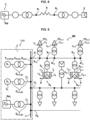
- microgrids In a second type of electrical systems, namely microgrids without distributed energy sources, the classic structure of microgrids consists of figure 2 in a single thermal power plant C composed of several production groups G 1 , G 2 , ... G M and connected to several feeders D 1 , D 2 , ..., D N of lines where PC l consumer stations are distributed , PC l+1 , PC l+2 .
- the voltage level generally corresponds to HTA (high voltage A for electrical installations in which the voltage exceeds 1000 volts without exceeding 50,000 volts in alternating current) or LV (low voltage for electrical installations in which the voltages are between 50 and 1000 volts in alternating voltage regime) and the impedance of the lines is mainly resistive in the case of overhead lines or resistive - capacitive in the case of underground lines.
- HTA high voltage A for electrical installations in which the voltage exceeds 1000 volts without exceeding 50,000 volts in alternating current
- LV low voltage for electrical installations in which the voltages are between 50 and 1000 volts in alternating voltage regime
- HTA and LV overhead lines can be modeled according to the Figure 3 with between the two electrical nodes N1 and N2 connected by the line a resistance R in series with a potentially non-negligible equivalent inductance X.
- the active and reactive powers P 1 , Q 1 both depend in these conditions both on the difference U 1 - U 2 of the effective values of the voltages and on the difference ⁇ 1 - ⁇ 2 of their angles.
- the thermal groups G 1 , G 2 , ...G M for producing a microgrid were distributed instead of being centralized as illustrated in Figure 4 , their control should be completely adapted to take into account the correlations UP and fQ: the voltage of the production groups G 1 , G 2 , ...G M would be modulated to regulate their active power and their frequency would be modulated to regulate their reactive power .
- the example below of the figure 5 represents two centralized production groups G 1 and G 2 , modeled in an equivalent manner downstream of their step-up transformer (network side), supplying a load consuming the reactive power Q R and modeled by an ideal current source, connected to the same electrical node N central as the centralized production groups G 1 and G 2 .
- the first terms X G 2 X G 1 + X G 2 3 U G 1 I R sin ⁇ G 1 ⁇ ⁇ R And X G 1 X G 1 + X G 2 3 U G 2 I R sin ⁇ G 2 ⁇ ⁇ R correspond to what can be considered to be the “natural contribution” of the production groups G 1 and G 2 to the supply of reactive power. This mainly depends on the term X G 2 X G 1 + X G 2 for group G 1 and the term X G 1 X G 1 + X G 2 for group G2 . These terms reflect the fact that the group G 1 or G 2 having the lowest equivalent reactance will provide more reactive power to the load than the group G 2 or G 1 having the greatest equivalent reactance.
- U G 1 U G 1 ⁇ U G 2 X G 1 + X G 2 And U G 2 U G 2 ⁇ U G 1 X G 1 + X G 2 correspond to what can be considered to be the “controlled contribution” of the production groups G 1 and G 2 to the supply of reactive power. They reflect the fact that the group G 1 or G 2 having the tension The highest stator voltage will provide more reactive power to the load than its natural contribution while the G 2 or G 1 group having the lowest stator voltage will provide less reactive power to the load than its natural contribution.
- the modulation of the voltages of the groups G 1 and G 2 makes it possible to control the injection of reactive power of the groups G 1 and G 2 .
- microgrids In a third type of electrical installations, the energy transition of microgrids results in certain cases in the installation of significant renewable energy capacities, in particular photovoltaic power plants, which can exceed several times the maximum active power consumption of microgrids. It is then essential to install a storage solution, often composed of electrochemical batteries.
- the set C of the batteries Bat and the thermal groups G 1 , G 2 , ... G M can be separated in relation to the sources S of renewable electricity production distributed with the consumer stations PC l , PC l+1 , PC l+2 on the departures D 1 , D 2 , ..., D N of lines by significant lengths of these overhead or underground MV or LV lines and it is therefore necessary to consider two levels of physical correlation: the correlations applicable at intra-central level C production groups - storage, the correlations between the power plant C and the sources S of decentralized electricity production.
- the reactive power supply equations are identical to those mentioned above for this second type if we replace the indices of the quantities relating to the group G 2 by the indices B of the battery Bat (voltage U B of the battery Bat, equivalent reactance X B of the battery Bat represented in Figure 7 ).
- the power plant C and the decentralized electricity production sources S being connected by MV or LV overhead lines, the applicable correlations are those of the second type of installations, that is to say U-P and f-Q.
- the photovoltaic decentralized electricity production source S can inject the maximum active power available thanks to a power point tracking algorithm (“maximum power point tracking” in English) and the battery Bat can maintain the voltage of the node N1 located on the side of the power plant C at a value close to the nominal voltage if it has a reactive power sharing algorithm or exactly at the nominal voltage if a secondary voltage adjustment algorithm is also used.
- a power point tracking algorithm (“maximum power point tracking” in English)
- the battery Bat can maintain the voltage of the node N1 located on the side of the power plant C at a value close to the nominal voltage if it has a reactive power sharing algorithm or exactly at the nominal voltage if a secondary voltage adjustment algorithm is also used.
- the effective value U 2 of the voltage at node N2 located on the side of the source S of decentralized photovoltaic electricity production can be calculated via the following equation, where U 1 is the effective value of the voltage at node N1: U 2 ⁇ U 1 ⁇ RP 1 U 1 ; with P 1 ⁇ 0
- the problem is that the existing voltage adjustment solutions composed of reactive power sharing algorithms coupled or not with a secondary voltage adjustment algorithm operating according to the state of the art are insufficient to ensure that the voltage is maintained. tension of the entire network in the presence of decentralized producers and do not make it possible to overcome the first and second disadvantages mentioned above.
- An objective of the invention is to obtain a device for controlling the voltage of microgrids by controlling at least one electricity production unit and/or at least one electricity storage unit, which overcomes the drawbacks mentioned above.
- a first object of the invention is a device for controlling a power plant according to claim 1.
- Claims 2 to 8 relate to embodiments of the control device.
- a second object of the invention is a method of controlling a power plant according to claim 9.
- a third object of the invention is a computer program according to claim 10.
- This control device 1000 is composed of a first central controller 100 corresponding to an energy management system (in English "energy management system") as well as a second controller A i per unit G i of electricity production and /or a second automaton A i per electricity storage unit Bat i .
- the index i indicates what is planned for each unit G i of electricity production and/or each second automaton A i associated with this unit G i of electricity production or this unit Bat i electricity storage.
- the second automaton of each electricity production unit G i or of each electricity storage unit Bat i regulates the internal voltage of this electricity production unit G i or of this electricity storage unit Bat i .
- the distributed electricity production sources S k , S k + 1 are connected to the electricity distribution line D 1 to be able to send it electric current and have nodes N 11 , N 12 for connection to the line D 1 , which are spaced at least a non-zero distance from each other and from connection terminal 10 along line D 1 .
- the distributed electricity production sources S k , S k+1 may also be or include distributed electricity storage units S k , S k+1 .
- each electricity distribution line for example the electricity transmission line D 1 as shown in Figure 9 , the distributed electricity consumer stations PC l , PC l+1 , PC l+2 are connected to the electricity transmission line D 1 to be able to receive electric current from it and have nodes N 13 , N 14 , N 15 for connection to line D 1 , which are spaced at least a non-zero distance from each other and from connection terminal 10 along line D 1 .
- fat energy designates the quantity of energy inevitably present or trapped in certain processes or products, which sometimes - at least in part - can be recovered and/or valorized.
- the term “fatal” also refers to the energy that would be lost if we did not use it when it is available, for example: electricity from wind turbines, solar panels, or that produced by hydraulic or tidal power stations. over the wire some water.
- the term “intermittent” refers to the fact that the unit produces energy part of the day, such as one or more photovoltaic panel(s), or in an irregular manner such as one or more wind turbines). These energy production units can use renewable energy, such as solar radiation for one or more photovoltaic panel(s), or the force of the wind for one or more wind turbines.
- the electricity generation unit(s) G i , the electricity storage unit(s) Bat i , the output conductor(s) 20 i and the connection terminal(s) 10 can be grouped together in an electricity production plant C.
- the connection terminal 10 is common to the electricity generation unit(s) G i and/or to the electricity storage unit(s) Bat i , and to the output conductor(s) 20 i , can also be called common electrical node 10 of the power plant C and can for example be a common busbar of the electricity production plant C.
- the central unit includes for example a single common connection terminal 10 or a single common electrical node 10.
- the electricity generation unit(s) G i can draw the electricity they produce from internal combustion engines, such as for example diesel engines via alternators and transformers, but could also be d another type, such as an electricity production plant, nuclear or coal, or hydroelectric or others.
- the Bat i electricity storage unit(s) may be or comprise one (or more) Bat i electricity storage battery, which may be equipped with an inverter.
- only one (or more) electricity generation unit G i can be provided, without electricity storage unit Bat i .
- only one (or more) electricity storage unit Bat i can be provided, without electricity generation unit G i .
- the device 1000 for controlling the unit(s) G i for generating electricity and/or the unit(s) Bat i for storing electricity and the method for controlling the (or des) unit G i for generating electricity and/or the unit(s) Bat i for storing electricity comprise and use the first automaton 100 for controlling the power plant C and the second automaton(s) A i control of the electricity generation unit G i (connected to the first control automaton 100) and/or the electricity storage unit Bat i and is configured to calculate (step E5 at Figure 17 ) a setpoint voltage U ref(i) of each electricity generation unit G i and/or a setpoint voltage U ref(i) of each electricity storage unit Bat.
- control automatons 100 and A i include for each electricity generation unit G i and/or each electricity storage unit Bat i and the steps implemented by the automaton 100 control in the process.
- the automatic control 100 comprises a first member 1 for measuring or determining a total central active power P leaving the central C, supplied or absorbed by the unit(s) G i for generating electricity and/or the Bat i electricity storage unit(s) on the common connection terminal 10 (step E1 carried out by this first body 1).
- the first measuring member 1 can for example be a measuring sensor on the common connection terminal 10.
- the first measuring member 1 can use a calculator adding measurements or determinations of individual active powers, carried out by measuring members (sensors or others) or determination members (calculator) forming part of the one or more devices.
- second automata A i on the output conductor(s) 20 i of each electricity generation unit G i and/or each electricity storage unit Bat i towards the connection terminal 10.
- the automatic control 100 comprises a second member 2 for measuring or determining a voltage U Rmes of the common connection terminal 10 (which could for example be a measurement sensor on the output conductor 20 i or on terminal 10 common connection), in step E2 carried out by this second member 2.
- This voltage U Rmes of the common connection terminal 10 is therefore the voltage U Rmes of the output conductor(s) 20 i of each unit G i of generation of electricity and/or each Bat i electricity storage unit.
- the control automaton 100 comprises a third element 3 for calculating (for example by a calculator) a central reference URef of voltage of the common connection terminal 10 according to a first prescribed function f depending at least on the total active power P central (step E3 carried out by this third organ 3).
- Each second control automaton A i comprises a fourth member 4 i for measuring or determining an individual reactive power Q mes(i) supplied or absorbed by the electricity generation unit (G i ) associated with this second automaton (A i ) and/or the electricity storage unit (Bat i ) associated with this second automaton (A i ) towards the common connection terminal 10 (step E4 carried out by this fourth member 4).
- the fourth measuring member 4 can for example be a measuring sensor on the output conductor 20 i of each electricity generation unit G i and/or of each electricity storage unit Bat i electricity to connection terminal 10.
- the control automaton 100 comprises a first voltage corrector 5, having a second prescribed transfer function corr.
- the control automaton 100 is configured to calculate at least a second offset voltage U offset(i) according to a third prescribed function gi depending on the first central offset voltage U offset .
- the control automaton 100 is configured to transmit the second offset voltage(s) U offset(i) to the second control automaton(s) A i for the output generation unit G i . electricity associated with this second automaton A i and/or for the electricity storage unit Bat i associated with this second automaton A i .
- the first central control automaton 100 calculates (step E6) and transmits (step E6) to each second control automaton A i the offset voltage U (i) of each electricity generation unit G i and/or of each Bat i electricity storage unit associated with this second control controller A i , so that the voltage of the common connection terminal 10 is adjusted to the central voltage reference URef .
- each coefficient K UQ(i) represents a sharing function of the first total reactive power Q mes and can correspond to the ratio of the individual reactive power Q mes(i) of a unit G i for generating electricity or Bat i for storing electricity relative to the first total reactive power Q mes , this sharing function being implemented in the second control automaton(s) A i .
- This function of sharing the first total reactive power Q mes is associated with the regulation of the internal voltage of each electricity generation unit G i and/or each electricity storage unit Bat i , carried out by the second automaton A i of control associated with this unit.
- the present invention makes it possible to adapt the operation of the secondary centralized voltage adjustment presented in the Figure 11 in order to minimize voltage differences on all the nodes of the MR micronetwork, in particular the nodes N 11 , N 12 for connecting the sources S k , S k+1 of distributed electricity production and the nodes N 13 , N 14 , No. 15 for connecting stations consumers PC l , PC l+1 , PC l+2 of electricity distributed, compared to the nominal voltage.
- the central voltage reference URef of the secondary setting is modulated as a function of the central total active power P and/or the first total reactive power Q mes injected by the central C on the microgrid MR.
- the first central control automaton 100 comprises another member 4 for measuring or determining the first total reactive power Q mes leaving the power plant C, supplied or absorbed by the electricity generation unit G i and/or l Bat i electricity storage unit.
- the measuring organ 4 can use a calculator adding measurements or determinations of the individual reactive powers Q mes(i) , which have been carried out by the measuring organs 4 i (sensors or others) or determination (calculator) making part of the second automaton(s) A i , on the output conductor(s) 20 i of each electricity generation unit G i and/or each electricity storage unit Bat i towards the connection terminal 10.
- the first central control automaton 100 comprises, as another organ 4, another organ 4 for measuring the first total reactive power Q mes leaving the power station, supplied or absorbed by the electricity generation unit G i and/ or the Bat i electricity storage unit on common connection terminal 10.
- the automaton 100, the first calculation module M1 and the second calculation module M2 i , the organs, the correctors, filters, limiters and other elements described below, can be produced by any calculation means, which may include a calculator, a computer, one or more processors, a calculation circuit, a computer program or others.
- the invention also relates to a computer program comprising code instructions for implementing the method of controlling at least one electricity generation unit G i and/or at least one storage unit Bat i electricity, when executed by the control automaton 100.
- the elements described below may implement other steps of the control process, described below.
- THE figures 11 , 22 And 23 shows an example of realization of a first module M1 for calculating the second offset voltage U offset(i) , where this first calculation module M1 comprises a first subtractor SOUS1 comprising a first adding input E10 receiving the central reference URef of voltage and a second subtractive input E20 receiving the voltage U Rmes from the common connection terminal 10 to provide on its first output SOR the central difference URef - U Rmes .
- the second SOR corr output is connected to the twenty-fourth EMULT7 input; of a seventh multiplier MULT7 i multiplying the first central offset voltage U offset by the inverse of the nominal voltage U iN prescribed to provide on a nineteenth output S MULT7, of the seventh multiplier MULT7, this second offset voltage U offset (i) .
- FIG. 12 shows an example of production of a second module M2 i for calculating the setpoint voltage U ref(i) , where this second calculation module M2 i comprises a first multiplier MULT i comprising a fourth input EMULT i receiving the individual reactive power Q mes(i) and providing on its third output SMULT i the product of the prescribed coefficient K UQ(i) by the individual reactive power Q mes(i) .
- this second calculation module M2 i comprises a first multiplier MULT i comprising a fourth input EMULT i receiving the individual reactive power Q mes(i) and providing on its third output SMULT i the product of the prescribed coefficient K UQ(i) by the individual reactive power Q mes(i) .
- the SMULT i output is connected to a fifth subtractor input E3 i of a second subtractor SOUS2 i , of which a sixth adding input E4 receives the second offset voltage U offset(i) and of which the fourth SOR output sub2i provides the voltage U ref(i) setpoint equal to the difference U offset(i) - KuQ(i).Qmes(i).
- the third calculation member 3 comprises a second multiplier MULT2 comprising a seventh input EMULT2 receiving the central active power P and supplying on its fifth output SMULT2 the product of the second prescribed coefficient K P by the central active power P.
- the third calculation member 3 comprises a third multiplier MULT3 comprising an eighth input EMULT3 receiving the reactive power Q meas and providing on its sixth output SMULT3 the product of the fourth prescribed coefficient K Q by the reactive power Q meas .
- the third calculation member 3 comprises a first adder ADD1 comprising a ninth adding input EADD11 connected to the fifth output SMULT2, a tenth adding input EADD12 connected to the eighth input EMULT3, an eleventh input EADD13 receiving the third prescribed coefficient U 0 , and a seventh SADD1 output providing central K P .P + K Q .Q meas + U 0 .
- the third calculation member 3 comprises a first filtering member F1 comprising a twelfth input EF1 connected to the seventh output SADD1.
- the filtering member F1 may include a first limiter LIM1 limiting on the eighth output SF1 of the filtering member F1 the values K P .P central + K Q .Q mes + U 0 to values which are greater than or equal to at a minimum value U min of strictly positive, prescribed voltage and which are less than or equal to a maximum value U max of strictly positive, prescribed voltage, as a central reference URef voltage.
- the maximum value U max of strictly positive voltage is greater than the minimum value U min of strictly positive voltage.
- the filtering member F1 may include a first low-pass filter FPB1 providing the values K P .P central + K Q .Q mes + U 0 filtered by a first low-pass filtering function prescribed on the eighth output SF1 of the filtering member F1 as central reference URef voltage.
- the filtering member F1 can include both the first limiter LIM1 and the first low-pass filter FPB1 to provide on the eighth output SF1 of the filtering member F1 the values K P .P central + K Q .Q mes + U 0 both limited by the first limiter LIM1 and filtered by the first low-pass filter FPB1 on the eighth output SF1 of the first limiter LIM1 as central reference URef voltage.
- the first prescribed function f comprises a hysteresis function fH having three different central reference levels URef of voltage (namely either the prescribed minimum value U min of voltage, or the maximum prescribed value U max of voltage, or the nominal value U N of prescribed voltage, which is greater than the prescribed minimum value U min of voltage and is less than the maximum prescribed value U max ) of voltage, according to the increasing or decreasing values of the total active central power P leaving the central C, supplied or absorbed by the electricity generation unit G i and/or the electricity storage unit Bat i on the common connection terminal 10.
- the hysteresis function fH is useful for example if the coefficients of the linear or affine function described above could not be determined or if the performance is not satisfactory.
- the central reference URef of voltage takes the nominal value U N of strictly positive and prescribed voltage (first case).
- the central voltage reference URef takes the minimum value U min of strictly positive and prescribed voltage (second case).
- the central voltage reference URef takes the maximum value U max of strictly positive and prescribed voltage (third case).
- the central voltage reference URef takes the nominal value U N of strictly positive and prescribed voltage (fourth case).
- the first case and the fourth case correspond for example to the fact that when the injection or absorption of central total active power P is low, the drop or rise in voltage on the microgrid MR will remain limited and the central secondary voltage URef will be maintained at its nominal value U N .
- the central voltage reference URef takes the minimum value U min of strictly positive and prescribed voltage (fifth case).
- the second case and the fifth case correspond for example to the fact that when the central total active power absorption P is significant, that is to say in the case of high production from the distributed sources S k , S k+1 , the secondary voltage reference U centralRef will be the low value U min .
- the central voltage reference URef takes the maximum value U max strictly positive and prescribed voltage (sixth case).
- the third case and the sixth case correspond for example to the fact that when the central total active power injection P is significant, typically during the peak daily consumption of the consumer stations PC l , PC l+1 , PC l+2 d electricity distributed, the central secondary voltage reference URef will be the high value U max .
- the third strictly positive prescribed value P 3 of active power is less than the second strictly positive prescribed value P 2 of active power.
- the fourth strictly negative prescribed active power value P 4 being less than the first strictly negative prescribed active power value P 1 .
- the third calculation member 3 comprises a second low-pass filter FPB2 comprising a thirteenth input EFPB2 receiving the central total active power P and supplying on its ninth output SFPB2 the central total active power P filtered by a second low-pass filtering function prescribed.
- the ninth output SFPB2 is connected to the hysteresis function fH which receives instead of the central total active power P the central total active power P having been filtered by a second prescribed low-pass filtering function of the second low-pass filter FPB2.
- the decentralized electricity production sources S k , S k + 1 can each be provided with a seventh measuring device 7 k , 7 k + 1 (for example measuring sensor) or for determining their first value U sources -decentralized-k for respective voltage telemetry and an eighth telecommunication member 8 k , 8 k+1 (for example transmitter) to transmit by a telecommunications network R these first values U sources-decentralized-k for voltage telemetry to the fifth receiving member 5 (which is for example a telecommunications receiver).
- a seventh measuring device 7 k , 7 k + 1 for example measuring sensor
- an eighth telecommunication member 8 k , 8 k+1 for example transmitter
- the decentralized electricity consumer stations PC l , PC l+1 , PC l+2 can each be provided with a ninth measuring member 9 l , 9 l+1 , 9 l+2 (for example measuring sensor) or determination of their second value U consumer posts-l of respective voltage telemetry and of a tenth telecommunications member 10 l , 10 l+1 , 10 l+2 (for example transmitter) for transmitting these second ones by a telecommunications network R values U consumer posts-l for voltage telemetry at the fifth receiving unit 5.
- a ninth measuring member 9 l , 9 l+1 , 9 l+2 for example measuring sensor
- a tenth telecommunications member 10 l , 10 l+1 , 10 l+2 for example transmitter
- the maximum voltage U Rmax on the microgrid necessarily corresponds to that of a distributed source providing active power according to the equations of the first type mentioned above.
- the minimum voltage U Rmin on the microgrid necessarily corresponds to that of a distributed consumer station absorbing active power according to the equations of the first type mentioned above.
- the third calculation unit 3 comprises a second adder ADD2 comprising a fourteenth adding input EADD21 receiving the maximum voltage U Rmax , a fifteenth adding input EADD22 receiving the minimum voltage U Rmin , and a tenth output SADD2 providing the sum of the maximum U Rmax voltage and minimum U Rmin voltage.
- the third calculation unit 3 comprises a fourth multiplier MULT4 comprising a sixteenth input EMULT4 connected to the tenth output SADD2 and providing on its eleventh output SMULT4 the half-sum of the maximum voltage U Rmax and the minimum U Rmin of voltage.
- the third calculation member 3 comprises a second corrector REG of the proportional, integrator and derivative (PID) type, providing on its twelfth output SREG the central voltage reference URef from the difference between on the one hand the prescribed nominal voltage U N and on the other hand the half-sum of the maximum voltage U Rmax and the minimum voltage U Rmin , this difference being applied to a seventeenth input EREG of the second corrector REG.
- PID proportional, integrator and derivative
- the third calculation member 3 comprises a second limiter LIM2 limiting on the twelfth output SREG of the second corrector REG the values of the central voltage reference URef to values, which are greater than or equal to the minimum value U min of strictly positive voltage , prescribed and which are less than or equal to the maximum value U max of strictly positive voltage, prescribed.
- the third calculation unit 3 i comprises a second subtractor SOUS2 comprising an eighteenth adding input ESOUS21 receiving the prescribed nominal voltage U N and a nineteenth subtracting input ESOUS22 receiving the half-sum of the maximum voltage U Rmax and the minimum U Rmin voltage, to provide on its ninth output SOR2 the difference between on the one hand the prescribed nominal voltage U N and on the other hand the half-sum of the maximum U Rmax voltage and the minimum U Rmin voltage.
- the ninth output SOR2 is connected to the seventeenth EREG input of the second REG corrector.
- the third calculation unit 3 may include a third low-pass filter FPB3 whose twentieth input EFPB3 is connected to the eleventh output SMULT4 to receive the half-sum of the maximum voltage U Rmax and the minimum U Rmin voltage.
- the third low-pass filter FPB3 includes a thirteenth output SFPB3 providing the half-sum of the maximum voltage U Rmax and the minimum voltage U Rmin , filtered by a third prescribed low-pass filtering function.
- the thirteenth output SFPB3 is connected to the nineteenth subtractive input ESOUS22.
- the control automaton 100 comprises a sixth unit 6 for calculating respective instructions Q decentralized-source-k , Q decentralized-source-k+1 of reactive power for the corresponding sources S k , S k+1 of production of decentralized electricity.
- These respective instructions Q decentralized-source-k , Q decentralized-source-k+1 are proportions r k , r k+1 at least of the first total reactive power Q mes leaving the power plant C, supplied or absorbed by the unit G i for generating electricity and/or the unit Bat i for storing electricity on common connection terminal 10 (thus being able to add other measured reactive powers, as described below).
- the automaton 100 control unit may include a twelfth telecommunications member 12 (for example transmitter) to transmit via a telecommunications network R these respective instructions Q decentralized-source-k , Q decentralized-source-k+1 to the corresponding sources S k , S k +1 decentralized electricity production (which may have a thirteenth receiving organ 13 k , 13 k+1 (for example a telecommunications receiver)) receiving these respective instructions Q decentralized-source-k , Q decentralized-source-k+ 1 by the telecommunications network R on their third control automaton A k .
- the third automaton A k , A k+1 for controlling each source S k , S k+1 of decentralized electricity production regulates the internal voltage of this source S k , S k+1 of decentralized electricity production.
- the control automaton 100 comprises a seventh receiving member 7 to receive third respective values Q mes-decentralized-source-k , Q mes-decentralized-source-k+1 for telemetry of reactive power from the respective sources S k , S k+1 of decentralized electricity production.
- the sixth calculation member 6 is configured to calculate a second total reactive power Q micronetwork equal to the algebraic sum SPR of the first total reactive power Q mes leaving the power plant C, supplied or absorbed by the power generation unit G i electricity and/or the unit Bat i for storing electricity on the connection terminal 10 and the third respective values Q mes-decentralized-source-k , Q mes-decentralized-source-k+1 for reactive power telemetry ( absorbed or injected) of the respective sources S k , S k+1 of distributed electricity production.
- the sources S k , S k+1 of decentralized electricity production can each be provided with an eleventh member 11 k , 11 k+1 for measuring (for example measuring sensor) or for determining their respective third value Q mes-decentralized-source-k , Q mes-decentralized-source-k+1 for reactive power telemetry and an eighth telecommunications unit 8 k , 8 k+1 (for example transmitter) for transmitting via a telecommunications network R these third respective values Q mes-decentralized-source-k , Q mes-decentralized-source-k+1 of reactive power telemetry to the seventh receiving body 7 (which has for example a telecommunications receiver).
- the seventh receiving body 7 which has for example a telecommunications receiver
- the sixth calculation unit 6 comprises a third adder ADD3 receiving on its inputs the first total reactive power Q mes leaving the power plant C, supplied or absorbed by the electricity generation unit G i and/or the Bat unit i of electricity storage on common connection terminal 10 t the third respective values Q mes-decentralized-source-k , Q mes-decentralized-source-k+1 of reactive power telemetry, and comprising a fourteenth SADD3 output providing the algebraic sum SPR of the first total reactive power Q mes leaving the power plant C, supplied or absorbed by the electricity generation unit G i and/or the electricity storage unit Bat i on terminal 10 of common connection and third respective values Q mes-decentralized-source-k , Q mes-decentralized-source-k+1 for telemetry of reactive power (absorbed or injected) of the respective sources S k , S k+1 for production of electricity distributed.
- a third adder ADD3 receiving on its inputs the first total reactive power Q mes leaving the power plant C, supplied or absorbed by the electricity generation
- the sixth calculation unit 6 comprises respective branches b k , b k+1 for calculating the respective instructions Q decentralized-source-k , Q decentralized-source-k+1 of reactive power from the respective sources S k , S k+1 distributed electricity production.
- Each respective branch b k of calculation comprises a fifth multiplier MULT5 k comprising a twenty-first input EMULT5 k connected to the fourteenth output SADD3 and providing on its fifteenth output SMULT5 k the product r k .SPR.
- Each respective branch b k+1 of calculation includes a sixth multiplier MULT5 k+1 comprising a twenty-second input EMULT5 k+1 connected to the fourteenth output SADD3 and providing on its sixteenth output SMULT5 k+1 the product r k+1 .SPR.
- the sixth calculation unit 6 may include a fourth low-pass filter FPB4 k , the twenty-second input EFPB4 k of which is connected to the fifteenth output SMULT5 k to receive the product r k .SPR.
- the fourth low-pass filter FPB4 k includes a seventeenth output SFPB4 k providing the product r k .SPR, filtered by a fourth low-pass filtering function prescribed as a respective setpoint Q source-decentralized-k of reactive power of the respective source S k of distributed electricity production.
- the sixth calculation unit 6 may include a fifth low-pass filter FPB4 k+1 whose twenty-third input EFPB4 k+1 is connected to the sixteenth output SMULT5 k+1 to receive the product r k+1 .SPR.
- the fifth low-pass filter FPB4 k+1 includes an eighteenth output SFPB4 k+1 providing the product r k+1 .SPR, filtered by a fifth low-pass filtering function prescribed as a respective source-decentralized setpoint Q -k+1 of reactive power of the respective source S k+1 of distributed electricity production.
- FIG 23 illustrates an architecture of embodiments of the invention of figures 11 to 16 , comprising the mode of realization of the FIG 13 or the mode of carrying out the FIG 14 or the mode of carrying out the FIG15 (OR function at Figure 23 ), combined with the embodiment of the FIG 11 , with the mode of realization of the FIG 12 and with the mode of realization of the FIG 16 (AND function at Figure 23 ).
- THE figures 18 to 21 illustrate a digital simulation in effective value of an example of a microgrid MR, the power plant C of which includes an electricity storage unit Bat i formed by a battery Bat i whose output conductor 20 i is connected to the connection terminal 10 common, itself connected by a first section D 1a of 2 km length of the electricity transmission line D 1 to a node N, which is connected by a second section D 1b of 10 km length of the line D 1 of electricity transmission to the respective source S k of decentralized electricity production of photovoltaic (PV) type and is connected by a third section D 1c of 5 km length of the line D 1 of electricity transmission to the station PC decentralized electricity consumer.
- the nominal voltage U N(i) of this MR microgrid is 20 kV.
- the installed power of this respective source S k of decentralized photovoltaic (PV) electricity production is 5 MW.
- the load (Pn / cos(phin)) of this decentralized PC l electricity consumer station is 2 MW / 0.9.
- These sections D 1a , D 1b , D 1c of the electricity transmission line D 1 are Phlox type 37.7mm 2 (R/X) cables of 1.176 Ohms/km / 0.399 Ohms/km. This Bat i battery has unlimited energy and power during simulations.
- FIG. 19 shows, over time on the abscissa, the profile of the active power (curve C1) of the respective source S k of decentralized electricity production of photovoltaic (PV) type, the profile of the active power (curve C2) of the station decentralized electricity consumer PC l and the profile of the active power (curve C3) of the battery Bat i .
- PV photovoltaic
- FIG. 20 shows, over time on the abscissa, the voltage at node N 12 (curve U1) of the respective source S k of decentralized electricity production of photovoltaic type (PV), the voltage at node N 13 (curve U2) of the station decentralized electricity consumer PC, the voltage on connection terminal 10 (curve U3) of the battery Bat; and the voltage of the common node N (curve U4) in the first scenario.
- the voltage on the ordinate is expressed as a reduced value (u(pu)) corresponding to U / 20 kV.
- FIG. 21 shows, over time on the abscissa, the voltage at node N 12 (INV1 curve) of the respective source S k of decentralized photovoltaic (PV) type electricity production, the voltage at node N 13 (INV2 curve) of the station decentralized electricity consumer PC l , the voltage on connection terminal 10 (INV3 curve) of the battery Bat; and the voltage of the common node N (INV4 curve) in the first scenario according to the invention.
- the voltage on the ordinate is expressed as a reduced value (u(pu)) corresponding to U / 20 kV.
- the second scenario according to the invention allows, in accordance with the objective of the present invention, to minimize voltage variations across the entire network by modulating the voltage (INV3 curve) of the power plant C comprising the battery Bat i (terminal 10).
- the voltage (INV3 curve) of the power plant C comprising the battery Bat i (terminal 10) is lowered significantly to limit the increase in voltage (INV1 curve) at node N 12 to approximately 8%, or almost half the voltage (INV1 curve) at node N 12.
Landscapes
- Engineering & Computer Science (AREA)
- Power Engineering (AREA)
- Control Of Electrical Variables (AREA)
- Control Of Eletrric Generators (AREA)
- Supply And Distribution Of Alternating Current (AREA)
Applications Claiming Priority (3)
| Application Number | Priority Date | Filing Date | Title |
|---|---|---|---|
| FR2011830A FR3116394B1 (fr) | 2020-11-18 | 2020-11-18 | Dispositif et procédé de contrôle de la tension des microréseaux |
| EP21824611.4A EP4248538A1 (de) | 2020-11-18 | 2021-11-17 | Vorrichtung und verfahren zur spannungsregelung von mikronetzen |
| PCT/FR2021/052029 WO2022106782A1 (fr) | 2020-11-18 | 2021-11-17 | Dispositif et procédé de contrôle de la tension des microréseaux |
Related Parent Applications (1)
| Application Number | Title | Priority Date | Filing Date |
|---|---|---|---|
| EP21824611.4A Division EP4248538A1 (de) | 2020-11-18 | 2021-11-17 | Vorrichtung und verfahren zur spannungsregelung von mikronetzen |
Publications (3)
| Publication Number | Publication Date |
|---|---|
| EP4322362A2 true EP4322362A2 (de) | 2024-02-14 |
| EP4322362A3 EP4322362A3 (de) | 2024-04-10 |
| EP4322362B1 EP4322362B1 (de) | 2025-09-10 |
Family
ID=75278091
Family Applications (2)
| Application Number | Title | Priority Date | Filing Date |
|---|---|---|---|
| EP23219745.9A Active EP4322362B1 (de) | 2020-11-18 | 2021-11-17 | Vorrichtung und verfahren zur steuerung der spannung von mikroarrays |
| EP21824611.4A Pending EP4248538A1 (de) | 2020-11-18 | 2021-11-17 | Vorrichtung und verfahren zur spannungsregelung von mikronetzen |
Family Applications After (1)
| Application Number | Title | Priority Date | Filing Date |
|---|---|---|---|
| EP21824611.4A Pending EP4248538A1 (de) | 2020-11-18 | 2021-11-17 | Vorrichtung und verfahren zur spannungsregelung von mikronetzen |
Country Status (5)
| Country | Link |
|---|---|
| US (1) | US12603501B2 (de) |
| EP (2) | EP4322362B1 (de) |
| CN (1) | CN116711176A (de) |
| FR (1) | FR3116394B1 (de) |
| WO (1) | WO2022106782A1 (de) |
Families Citing this family (1)
| Publication number | Priority date | Publication date | Assignee | Title |
|---|---|---|---|---|
| GB2610634A (en) * | 2021-09-13 | 2023-03-15 | Eaton Intelligent Power Ltd | Device and method of managing power in an AC subgrid |
Citations (1)
| Publication number | Priority date | Publication date | Assignee | Title |
|---|---|---|---|---|
| KR20140098431A (ko) * | 2013-01-31 | 2014-08-08 | 명지대학교 산학협력단 | 독립형 dc 마이크로그리드를 위한 협조적 드룹 제어 장치 및 방법 |
Family Cites Families (8)
| Publication number | Priority date | Publication date | Assignee | Title |
|---|---|---|---|---|
| WO2013087085A1 (en) * | 2011-12-16 | 2013-06-20 | Fachhochschule Südwestfalen | Method for active control of frequency and voltage in a power supply grid with decentralized power supply systems |
| CN112398141B (zh) * | 2013-08-21 | 2024-12-10 | 施耐德电气It公司 | 用于提供电源接口的设备和方法 |
| US10027118B2 (en) * | 2016-05-19 | 2018-07-17 | General Electric Company | System and method for balancing reactive power loading between renewable energy power systems |
| IT201600131878A1 (it) * | 2016-12-28 | 2018-06-28 | Electro Power Systems Mfg S R L | Sistema di controllo di microreti di produzione e distribuzione di energia elettrica proveniente da più fonti di produzione di tipo diverso, e relativo metodo di controllo |
| CN109980676B (zh) * | 2017-12-28 | 2021-06-25 | 北京天诚同创电气有限公司 | 微电网控制系统及微电网 |
| CN109038644B (zh) * | 2018-06-26 | 2023-02-07 | 中国电力科学研究院有限公司 | 一种微能源网系统及其调压控制方法 |
| CN108777493B (zh) * | 2018-07-24 | 2020-12-15 | 杭州电子科技大学 | 一种基于灵敏度矩阵的低压微网二次电压控制方法 |
| EP3709480B1 (de) * | 2019-02-22 | 2024-05-01 | Hitachi Energy Ltd | Verfahren zur steuerung eines mikronetzes, energiemanagementsystem, und mikronetz |
-
2020
- 2020-11-18 FR FR2011830A patent/FR3116394B1/fr active Active
-
2021
- 2021-11-17 WO PCT/FR2021/052029 patent/WO2022106782A1/fr not_active Ceased
- 2021-11-17 US US18/037,360 patent/US12603501B2/en active Active
- 2021-11-17 EP EP23219745.9A patent/EP4322362B1/de active Active
- 2021-11-17 CN CN202180091078.7A patent/CN116711176A/zh active Pending
- 2021-11-17 EP EP21824611.4A patent/EP4248538A1/de active Pending
Patent Citations (1)
| Publication number | Priority date | Publication date | Assignee | Title |
|---|---|---|---|---|
| KR20140098431A (ko) * | 2013-01-31 | 2014-08-08 | 명지대학교 산학협력단 | 독립형 dc 마이크로그리드를 위한 협조적 드룹 제어 장치 및 방법 |
Also Published As
| Publication number | Publication date |
|---|---|
| FR3116394A1 (fr) | 2022-05-20 |
| US20230420945A1 (en) | 2023-12-28 |
| EP4248538A1 (de) | 2023-09-27 |
| EP4322362A3 (de) | 2024-04-10 |
| WO2022106782A1 (fr) | 2022-05-27 |
| CN116711176A (zh) | 2023-09-05 |
| FR3116394B1 (fr) | 2023-07-07 |
| US12603501B2 (en) | 2026-04-14 |
| EP4322362B1 (de) | 2025-09-10 |
Similar Documents
| Publication | Publication Date | Title |
|---|---|---|
| EP3818606B1 (de) | Verfahren zur modellierung des betriebs einer industrieanlage, angewandt auf industrieanlagen, öffentliche netze, mikronetze und eingebettete systeme | |
| FR2996032A1 (fr) | Procede de determination d'une prevision de la puissance electrique fournie par une installation de fourniture d'energie electrique | |
| EP3598598B1 (de) | Verfahren und system zur bestimmung eines spannungszustands eines an wenigstens einer transformatorstation liegenden niederspannungsnetzes | |
| EP2237387B1 (de) | Power supply system and charging control method for electrochemical generators | |
| EP2917992A1 (de) | Verfahren zur steuerung eines vsc-hvdc-netzwerks mit mehreren endgeräten | |
| Karandeh et al. | Optimal scheduling of battery energy storage systems for solar power smoothing | |
| EP2347492B1 (de) | System und verfahren zum steuern mindestens eines spannungsumrichters mit mehreren zellen in reihe | |
| EP4322362B1 (de) | Vorrichtung und verfahren zur steuerung der spannung von mikroarrays | |
| FR3055753B1 (fr) | Procede de controle d'une centrale de production electrique | |
| WO2023111166A1 (fr) | Dispositif, procédé et programme d'ordinateur de pilotage d'une source de tension | |
| EP4203222B1 (de) | Verfahren zur gemeinsamen spannungsregelung in einem mittelspannungszweig und niederspannungszweig mit einem dreiphasigen niederspannungszweig | |
| WO2015075372A1 (fr) | Procédé de réglage de la fréquence d'un réseau électrique | |
| FR3068530B1 (fr) | Procede de distribution d'une energie electrique issue d'une energie solaire a une pluralite de groupes d'au moins une installation electrique | |
| EP4020738A1 (de) | Verfahren und system zur gemeinsamen regulierung einer spannung in einem mittelspannungszweig und in einer vielzahl von niederspannungszweigen | |
| WO2018202353A1 (fr) | Optimisation de chaînes photovoltaïques à bus partagé | |
| FR3028080A1 (fr) | Methode de gestion de la distribution d'energie electrique en temps reel sur un reseau ilote | |
| EP3979163B1 (de) | Optimierung der in einem mini-netz verfügbaren energie | |
| EP2533391B1 (de) | Multi-Source-Steuerungssystem von Stromgeneratoren | |
| Yeh et al. | Battery placement on performance of VAR controls | |
| WO2015063208A1 (fr) | Procede d'optimisation de la consommation et de la production d'une installation electrique | |
| WO2022029376A1 (fr) | Procede de supervision energetique d'un systeme electrique equipe de charges pilotables | |
| WO2024126107A1 (fr) | Procede de determination de flux electriques au sein d'une communaute d'energie | |
| WO2022031157A1 (fr) | Une méthode de contrôle des onduleurs de source de tension pour la flexibilité des microréseaux électriques à courant alternatif | |
| FR3029024A1 (fr) | Procede d'optimisation de l'energie electrique d'appoint fournie par une source auxiliaire |
Legal Events
| Date | Code | Title | Description |
|---|---|---|---|
| PUAI | Public reference made under article 153(3) epc to a published international application that has entered the european phase |
Free format text: ORIGINAL CODE: 0009012 |
|
| STAA | Information on the status of an ep patent application or granted ep patent |
Free format text: STATUS: REQUEST FOR EXAMINATION WAS MADE |
|
| 17P | Request for examination filed |
Effective date: 20231222 |
|
| AC | Divisional application: reference to earlier application |
Ref document number: 4248538 Country of ref document: EP Kind code of ref document: P |
|
| AK | Designated contracting states |
Kind code of ref document: A2 Designated state(s): AL AT BE BG CH CY CZ DE DK EE ES FI FR GB GR HR HU IE IS IT LI LT LU LV MC MK MT NL NO PL PT RO RS SE SI SK SM TR |
|
| REG | Reference to a national code |
Ref country code: DE Free format text: PREVIOUS MAIN CLASS: H02J0003500000 Ref country code: DE Ref legal event code: R079 Ref document number: 602021038574 Country of ref document: DE Free format text: PREVIOUS MAIN CLASS: H02J0003500000 Ipc: H02J0003160000 |
|
| PUAL | Search report despatched |
Free format text: ORIGINAL CODE: 0009013 |
|
| AK | Designated contracting states |
Kind code of ref document: A3 Designated state(s): AL AT BE BG CH CY CZ DE DK EE ES FI FR GB GR HR HU IE IS IT LI LT LU LV MC MK MT NL NO PL PT RO RS SE SI SK SM TR |
|
| RIC1 | Information provided on ipc code assigned before grant |
Ipc: H02J 3/50 20060101ALI20240301BHEP Ipc: H02J 3/48 20060101ALI20240301BHEP Ipc: H02J 3/38 20060101ALI20240301BHEP Ipc: H02J 3/32 20060101ALI20240301BHEP Ipc: H02J 3/16 20060101AFI20240301BHEP |
|
| GRAP | Despatch of communication of intention to grant a patent |
Free format text: ORIGINAL CODE: EPIDOSNIGR1 |
|
| STAA | Information on the status of an ep patent application or granted ep patent |
Free format text: STATUS: GRANT OF PATENT IS INTENDED |
|
| INTG | Intention to grant announced |
Effective date: 20250401 |
|
| RIN1 | Information on inventor provided before grant (corrected) |
Inventor name: BENAVENT, FABIEN |
|
| GRAS | Grant fee paid |
Free format text: ORIGINAL CODE: EPIDOSNIGR3 |
|
| GRAA | (expected) grant |
Free format text: ORIGINAL CODE: 0009210 |
|
| STAA | Information on the status of an ep patent application or granted ep patent |
Free format text: STATUS: THE PATENT HAS BEEN GRANTED |
|
| AC | Divisional application: reference to earlier application |
Ref document number: 4248538 Country of ref document: EP Kind code of ref document: P |
|
| AK | Designated contracting states |
Kind code of ref document: B1 Designated state(s): AL AT BE BG CH CY CZ DE DK EE ES FI FR GB GR HR HU IE IS IT LI LT LU LV MC MK MT NL NO PL PT RO RS SE SI SK SM TR |
|
| REG | Reference to a national code |
Ref country code: GB Ref legal event code: FG4D Free format text: NOT ENGLISH |
|
| REG | Reference to a national code |
Ref country code: CH Ref legal event code: EP |
|
| REG | Reference to a national code |
Ref country code: DE Ref legal event code: R096 Ref document number: 602021038574 Country of ref document: DE |
|
| REG | Reference to a national code |
Ref country code: IE Ref legal event code: FG4D Free format text: LANGUAGE OF EP DOCUMENT: FRENCH |
|
| PG25 | Lapsed in a contracting state [announced via postgrant information from national office to epo] |
Ref country code: NO Free format text: LAPSE BECAUSE OF FAILURE TO SUBMIT A TRANSLATION OF THE DESCRIPTION OR TO PAY THE FEE WITHIN THE PRESCRIBED TIME-LIMIT Effective date: 20251210 |
|
| REG | Reference to a national code |
Ref country code: LT Ref legal event code: MG9D |
|
| PGFP | Annual fee paid to national office [announced via postgrant information from national office to epo] |
Ref country code: AT Payment date: 20260113 Year of fee payment: 5 |
|
| PG25 | Lapsed in a contracting state [announced via postgrant information from national office to epo] |
Ref country code: FI Free format text: LAPSE BECAUSE OF FAILURE TO SUBMIT A TRANSLATION OF THE DESCRIPTION OR TO PAY THE FEE WITHIN THE PRESCRIBED TIME-LIMIT Effective date: 20250910 |
|
| REG | Reference to a national code |
Ref country code: NL Ref legal event code: MP Effective date: 20250910 |
|
| PG25 | Lapsed in a contracting state [announced via postgrant information from national office to epo] |
Ref country code: HR Free format text: LAPSE BECAUSE OF FAILURE TO SUBMIT A TRANSLATION OF THE DESCRIPTION OR TO PAY THE FEE WITHIN THE PRESCRIBED TIME-LIMIT Effective date: 20250910 |
|
| PGFP | Annual fee paid to national office [announced via postgrant information from national office to epo] |
Ref country code: FR Payment date: 20251014 Year of fee payment: 5 |
|
| PG25 | Lapsed in a contracting state [announced via postgrant information from national office to epo] |
Ref country code: GR Free format text: LAPSE BECAUSE OF FAILURE TO SUBMIT A TRANSLATION OF THE DESCRIPTION OR TO PAY THE FEE WITHIN THE PRESCRIBED TIME-LIMIT Effective date: 20251211 |
|
| PG25 | Lapsed in a contracting state [announced via postgrant information from national office to epo] |
Ref country code: SE Free format text: LAPSE BECAUSE OF FAILURE TO SUBMIT A TRANSLATION OF THE DESCRIPTION OR TO PAY THE FEE WITHIN THE PRESCRIBED TIME-LIMIT Effective date: 20250910 |
|
| PG25 | Lapsed in a contracting state [announced via postgrant information from national office to epo] |
Ref country code: LV Free format text: LAPSE BECAUSE OF FAILURE TO SUBMIT A TRANSLATION OF THE DESCRIPTION OR TO PAY THE FEE WITHIN THE PRESCRIBED TIME-LIMIT Effective date: 20250910 |
|
| PG25 | Lapsed in a contracting state [announced via postgrant information from national office to epo] |
Ref country code: PL Free format text: LAPSE BECAUSE OF FAILURE TO SUBMIT A TRANSLATION OF THE DESCRIPTION OR TO PAY THE FEE WITHIN THE PRESCRIBED TIME-LIMIT Effective date: 20250910 Ref country code: BG Free format text: LAPSE BECAUSE OF FAILURE TO SUBMIT A TRANSLATION OF THE DESCRIPTION OR TO PAY THE FEE WITHIN THE PRESCRIBED TIME-LIMIT Effective date: 20250910 |
|
| PG25 | Lapsed in a contracting state [announced via postgrant information from national office to epo] |
Ref country code: RS Free format text: LAPSE BECAUSE OF FAILURE TO SUBMIT A TRANSLATION OF THE DESCRIPTION OR TO PAY THE FEE WITHIN THE PRESCRIBED TIME-LIMIT Effective date: 20251210 |
|
| PG25 | Lapsed in a contracting state [announced via postgrant information from national office to epo] |
Ref country code: ES Free format text: LAPSE BECAUSE OF FAILURE TO SUBMIT A TRANSLATION OF THE DESCRIPTION OR TO PAY THE FEE WITHIN THE PRESCRIBED TIME-LIMIT Effective date: 20250910 |
|
| REG | Reference to a national code |
Ref country code: AT Ref legal event code: MK05 Ref document number: 1836935 Country of ref document: AT Kind code of ref document: T Effective date: 20250910 |
|
| PG25 | Lapsed in a contracting state [announced via postgrant information from national office to epo] |
Ref country code: NL Free format text: LAPSE BECAUSE OF FAILURE TO SUBMIT A TRANSLATION OF THE DESCRIPTION OR TO PAY THE FEE WITHIN THE PRESCRIBED TIME-LIMIT Effective date: 20250910 |
|
| PG25 | Lapsed in a contracting state [announced via postgrant information from national office to epo] |
Ref country code: SM Free format text: LAPSE BECAUSE OF FAILURE TO SUBMIT A TRANSLATION OF THE DESCRIPTION OR TO PAY THE FEE WITHIN THE PRESCRIBED TIME-LIMIT Effective date: 20250910 |
|
| PG25 | Lapsed in a contracting state [announced via postgrant information from national office to epo] |
Ref country code: AT Free format text: LAPSE BECAUSE OF FAILURE TO SUBMIT A TRANSLATION OF THE DESCRIPTION OR TO PAY THE FEE WITHIN THE PRESCRIBED TIME-LIMIT Effective date: 20250910 |
|
| PG25 | Lapsed in a contracting state [announced via postgrant information from national office to epo] |
Ref country code: IT Free format text: LAPSE BECAUSE OF FAILURE TO SUBMIT A TRANSLATION OF THE DESCRIPTION OR TO PAY THE FEE WITHIN THE PRESCRIBED TIME-LIMIT Effective date: 20250910 Ref country code: RO Free format text: LAPSE BECAUSE OF FAILURE TO SUBMIT A TRANSLATION OF THE DESCRIPTION OR TO PAY THE FEE WITHIN THE PRESCRIBED TIME-LIMIT Effective date: 20250910 |
|
| PG25 | Lapsed in a contracting state [announced via postgrant information from national office to epo] |
Ref country code: IS Free format text: LAPSE BECAUSE OF FAILURE TO SUBMIT A TRANSLATION OF THE DESCRIPTION OR TO PAY THE FEE WITHIN THE PRESCRIBED TIME-LIMIT Effective date: 20260110 |
|
| PG25 | Lapsed in a contracting state [announced via postgrant information from national office to epo] |
Ref country code: CZ Free format text: LAPSE BECAUSE OF FAILURE TO SUBMIT A TRANSLATION OF THE DESCRIPTION OR TO PAY THE FEE WITHIN THE PRESCRIBED TIME-LIMIT Effective date: 20250910 Ref country code: PT Free format text: LAPSE BECAUSE OF FAILURE TO SUBMIT A TRANSLATION OF THE DESCRIPTION OR TO PAY THE FEE WITHIN THE PRESCRIBED TIME-LIMIT Effective date: 20260112 |
|
| PG25 | Lapsed in a contracting state [announced via postgrant information from national office to epo] |
Ref country code: SK Free format text: LAPSE BECAUSE OF FAILURE TO SUBMIT A TRANSLATION OF THE DESCRIPTION OR TO PAY THE FEE WITHIN THE PRESCRIBED TIME-LIMIT Effective date: 20250910 Ref country code: EE Free format text: LAPSE BECAUSE OF FAILURE TO SUBMIT A TRANSLATION OF THE DESCRIPTION OR TO PAY THE FEE WITHIN THE PRESCRIBED TIME-LIMIT Effective date: 20250910 |