EP4322679A1 - Procédé et dispositif pour émettre un signal à travers une pluralité de créneaux dans un système de communication sans fil - Google Patents
Procédé et dispositif pour émettre un signal à travers une pluralité de créneaux dans un système de communication sans fil Download PDFInfo
- Publication number
- EP4322679A1 EP4322679A1 EP22807646.9A EP22807646A EP4322679A1 EP 4322679 A1 EP4322679 A1 EP 4322679A1 EP 22807646 A EP22807646 A EP 22807646A EP 4322679 A1 EP4322679 A1 EP 4322679A1
- Authority
- EP
- European Patent Office
- Prior art keywords
- pusch
- tboms
- slots
- slot
- base station
- Prior art date
- Legal status (The legal status is an assumption and is not a legal conclusion. Google has not performed a legal analysis and makes no representation as to the accuracy of the status listed.)
- Pending
Links
Images




Classifications
-
- H—ELECTRICITY
- H04—ELECTRIC COMMUNICATION TECHNIQUE
- H04W—WIRELESS COMMUNICATION NETWORKS
- H04W72/00—Local resource management
- H04W72/12—Wireless traffic scheduling
- H04W72/1263—Mapping of traffic onto schedule, e.g. scheduled allocation or multiplexing of flows
- H04W72/1268—Mapping of traffic onto schedule, e.g. scheduled allocation or multiplexing of flows of uplink data flows
-
- H—ELECTRICITY
- H04—ELECTRIC COMMUNICATION TECHNIQUE
- H04L—TRANSMISSION OF DIGITAL INFORMATION, e.g. TELEGRAPHIC COMMUNICATION
- H04L5/00—Arrangements affording multiple use of the transmission path
- H04L5/003—Arrangements for allocating sub-channels of the transmission path
- H04L5/0044—Allocation of payload; Allocation of data channels, e.g. PDSCH or PUSCH
-
- H—ELECTRICITY
- H04—ELECTRIC COMMUNICATION TECHNIQUE
- H04W—WIRELESS COMMUNICATION NETWORKS
- H04W72/00—Local resource management
- H04W72/04—Wireless resource allocation
- H04W72/044—Wireless resource allocation based on the type of the allocated resource
- H04W72/0446—Resources in time domain, e.g. slots or frames
-
- H—ELECTRICITY
- H04—ELECTRIC COMMUNICATION TECHNIQUE
- H04W—WIRELESS COMMUNICATION NETWORKS
- H04W72/00—Local resource management
- H04W72/20—Control channels or signalling for resource management
- H04W72/23—Control channels or signalling for resource management in the downlink direction of a wireless link, i.e. towards a terminal
- H04W72/232—Control channels or signalling for resource management in the downlink direction of a wireless link, i.e. towards a terminal the control data signalling from the physical layer, e.g. DCI signalling
-
- H—ELECTRICITY
- H04—ELECTRIC COMMUNICATION TECHNIQUE
- H04L—TRANSMISSION OF DIGITAL INFORMATION, e.g. TELEGRAPHIC COMMUNICATION
- H04L1/00—Arrangements for detecting or preventing errors in the information received
- H04L1/12—Arrangements for detecting or preventing errors in the information received by using return channel
- H04L1/16—Arrangements for detecting or preventing errors in the information received by using return channel in which the return channel carries supervisory signals, e.g. repetition request signals
- H04L1/18—Automatic repetition systems, e.g. Van Duuren systems
- H04L1/1867—Arrangements specially adapted for the transmitter end
- H04L1/1896—ARQ related signaling
-
- H—ELECTRICITY
- H04—ELECTRIC COMMUNICATION TECHNIQUE
- H04W—WIRELESS COMMUNICATION NETWORKS
- H04W72/00—Local resource management
- H04W72/20—Control channels or signalling for resource management
- H04W72/23—Control channels or signalling for resource management in the downlink direction of a wireless link, i.e. towards a terminal
Definitions
- the disclosure relates to a method and a device for transmitting signals through a plurality of slots in a wireless communication system.
- the 5G or pre-5G communication system is also called a “beyond 4G Network” communication system or a "post LTE” system.
- the 5G communication system defined by 3GPP is called a "new radio (NR) system”.
- the 5G communication system is considered to be implemented in ultrahigh frequency (mmWave) bands (e.g., 60GHz bands) so as to accomplish higher data rates.
- mmWave ultrahigh frequency
- FQAM FSK and QAM modulation
- SWSC sliding window superposition coding
- ACM advanced coding modulation
- FBMC filter bank multi carrier
- NOMA non-orthogonal multiple access
- SCMA sparse code multiple access
- the Internet which is a human centered connectivity network where humans generate and consume information
- IoT Internet of things
- IoE Internet of everything
- sensing technology “wired/wireless communication and network infrastructure”, “service interface technology”, and “security technology”
- M2M machine-to-machine
- MTC machine type communication
- IoT Internet technology
- IoT may be applied to a variety of fields including smart home, smart building, smart city, smart car or connected cars, smart grid, health care, smart appliances and advanced medical services through convergence and combination between existing information technology (IT) and various industrial applications.
- technologies such as a sensor network, machine type communication (MTC), and machine-to-machine (M2M) communication may be implemented by beamforming, MIMO, and array antennas.
- MTC machine type communication
- M2M machine-to-machine
- Application of a cloud radio access network (cloud RAN) as the above-described big data processing technology may also be considered an example of convergence of the 5G technology with the loT technology.
- the disclosure proposes a method and a device for an effective signal processing method when the number of transport blocks and the number of slots or physical channels are not the same (hereinafter referred to as asymmetric transmission) in a communication system.
- a method of a UE in a wireless communication system may include receiving transport block over multi-slot (TBoMS) configuration information including one transport block from a base station; receiving downlink control information for scheduling transmission of a physical uplink shared channel (PUSCH) from the base station; performing a physical layer signal processing procedure based on the TBoMS configuration information and downlink control information; and transmitting the PUSCH to the base station in a plurality of slots.
- TBoMS transport block over multi-slot
- PUSCH physical uplink shared channel
- the downlink control information may include DCI format 0 0.
- the TBoMS configuration information may include information on the number of slots for transmitting the one transport block, and the transport block size (TBS) related to the transport block may be determined based on the number of slots.
- TBS transport block size
- code block segmentation for the transport block may be performed in the physical layer signal processing procedure.
- a method of a base station in a wireless communication system may include transmitting transport block over multi-slot (TBoMS) configuration information including one transport block to a UE; transmitting downlink control information for scheduling transmission of a physical uplink shared channel (PUSCH) to the UE; and receiving the PUSCH transmitted based on a physical layer signal processing procedure performed based on the TBoMS configuration information and downlink control information from the UE in a plurality of slots.
- TBoMS transport block over multi-slot
- a UE in a wireless communication system may include a transceiver; and a controller configured to receive transport block over multi-slot (TBoMS) configuration information including one transport block from a base station, receive downlink control information for scheduling transmission of a physical uplink shared channel (PUSCH) from the base station, perform a physical layer signal processing procedure based on the TBoMS configuration information and downlink control information, and transmit the PUSCH to the base station in a plurality of slots.
- TBoMS transport block over multi-slot
- a base station in a wireless communication system may include a transceiver; and a controller configured to transmit transport block over multi-slot (TBoMS) configuration information including one transport block to a UE, transmit downlink control information for scheduling transmission of a physical uplink shared channel (PUSCH) to the UE, and receive the PUSCH transmitted based on a physical layer signal processing procedure performed based on the TBoMS configuration information and downlink control information from the UE in a plurality of slots.
- TBoMS transport block over multi-slot
- the disclosure proposes a method and device for an effective signal processing method for asymmetric transmission.
- additional channel coding gain may be obtained, and coverage of an uplink channel may be improved.
- the contents of the disclosure may be applied to near field communication systems including WiFi employing asymmetrical transmission and mobile communication systems including LTE, NR, and 6 systems. Furthermore, based on determinations by those skilled in the art, the disclosure may also be applied to other communication systems through some modifications without significantly departing from the scope of the disclosure.
- descriptions related to technical contents well-known in the art and not associated directly with the disclosure will be omitted. Such an omission of unnecessary descriptions is intended to prevent obscuring of the main idea of the disclosure and more clearly transfer the main idea.
- a base station is an entity that allocates resources to terminals, and may be at least one of a gNode B, an eNode B, a Node B, a base station (BS), a wireless access unit, a base station controller, and a node on a network.
- a terminal may include a user equipment (UE), a mobile station (MS), a cellular phone, a smartphone, a computer, or a multimedia system capable of performing communication functions.
- a "downlink (DL)” refers to a radio link via which a base station transmits a signal to a terminal
- an "uplink (UL)” refers to a radio link via which a terminal transmits a signal to a base station
- a "sidelink (SL)” refers to a radio transmission link between a terminal and a terminal.
- an NR system may be described by way of example, but the embodiments of the disclosure may also be applied to other communication systems having similar technical backgrounds or channel types.
- each block of the flowchart illustrations, and combinations of blocks in the flowchart illustrations can be implemented by computer program instructions.
- These computer program instructions can be provided to a processor of a general purpose computer, special purpose computer, or other programmable data processing apparatus to produce a machine, such that the instructions, which execute via the processor of the computer or other programmable data processing apparatus, create means for implementing the functions specified in the flowchart block or blocks.
- These computer program instructions may also be stored in a computer usable or computer-readable memory that can direct a computer or other programmable data processing apparatus to function in a particular manner, such that the instructions stored in the computer usable or computer-readable memory produce an article of manufacture including instruction means that implement the function specified in the flowchart block or blocks.
- the computer program instructions may also be loaded onto a computer or other programmable data processing apparatus to cause a series of operational steps to be performed on the computer or other programmable apparatus to produce a computer implemented process such that the instructions that execute on the computer or other programmable apparatus provide steps for implementing the functions specified in the flowchart block or blocks.
- each block of the flowchart illustrations may represent a module, segment, or portion of code, which includes one or more executable instructions for implementing the specified logical function(s). It should also be noted that in some alternative implementations, the functions noted in the blocks may occur out of the order. For example, two blocks shown in succession may in fact be executed substantially concurrently or the blocks may sometimes be executed in the reverse order, depending upon the functionality involved.
- the "unit” refers to a software element or a hardware element, such as a Field Programmable Gate Array (FPGA) or an Application Specific Integrated Circuit (ASIC), which performs a predetermined function.
- FPGA Field Programmable Gate Array
- ASIC Application Specific Integrated Circuit
- the "unit” does not always have a meaning limited to software or hardware.
- the “unit” may be constructed either to be stored in an addressable storage medium or to execute one or more processors. Therefore, the "unit” includes, for example, software elements, object-oriented software elements, class elements or task elements, processes, functions, properties, procedures, sub-routines, segments of a program code, drivers, firmware, micro-codes, circuits, data, database, data structures, tables, arrays, and parameters.
- the elements and functions provided by the "unit” may be either combined into a smaller number of elements, or a “unit”, or divided into a larger number of elements, or a “unit”. Moreover, the elements and “units” or may be implemented to reproduce one or more CPUs within a device or a security multimedia card. Furthermore, the "unit” in the embodiments may include one or more processors.
- the method and device proposed in the embodiments of the disclosure will describe the embodiments of the disclosure as an example the PUSCH design, but may be applied to UL, DL, and SL channels of various systems applying asymmetric transmission, such as PDSCH and PSSCH. That is, the disclosure is not limited to each embodiment, and may be applied to a method for configuring frequency resources corresponding to other channels by using all or a combination of one or more embodiments proposed in the disclosure. Accordingly, the embodiments of the disclosure may be applied through some modifications within a range that does not significantly deviate from the scope of the disclosure by the judgment of a skilled person with technical knowledge.
- a wireless communication system is advancing to a broadband wireless communication system for providing high-speed and high-quality packet data services using communication standards, such as high-speed packet access (HSPA) of 3GPP, LTE ⁇ long-term evolution or evolved universal terrestrial radio access (E-UTRA) ⁇ , LTE-Advanced (LTE-A), LTE-Pro, high-rate packet data (HRPD) of 3GPP2, ultra-mobile broadband (UMB), IEEE 802.17e, and the like, as well as typical voice-based services.
- HSPA high-speed packet access
- E-UTRA evolved universal terrestrial radio access
- LTE-A LTE-Advanced
- LTE-Pro LTE-Pro
- HRPD high-rate packet data
- UMB ultra-mobile broadband
- IEEE 802.17e IEEE 802.17e
- an LTE system employs an orthogonal frequency division multiplexing (OFDM) scheme in a downlink (DL) and employs a single carrier frequency division multiple access (SC-FDMA) scheme in an uplink (UL).
- the uplink indicates a radio link through which a user equipment (UE) (or a mobile station (MS)) transmits data or control signals to a base station (BS) (eNode B), and the downlink indicates a radio link through which the base station transmits data or control signals to the UE.
- the above multiple access scheme separates data or control information of respective users by allocating and operating time-frequency resources for transmitting the data or control information for each user so as to avoid overlapping each other, that is, so as to establish orthogonality.
- a 5G communication system which is a post-LTE communication system, must freely reflect various requirements of users, service providers, and the like, services satisfying various requirements must be supported.
- the services considered in the 5G communication system include enhanced mobile broadband (eMBB) communication, massive machine-type communication (mMTC), ultra-reliability low-latency communication (URLLC), and the like.
- eMBB aims at providing a data rate higher than that supported by existing LTE, LTE-A, or LTE-Pro.
- eMBB must provide a peak data rate of 20 Gbps in the downlink and a peak data rate of 10 Gbps in the uplink for a single base station.
- the 5G communication system must provide an increased user-perceived data rate to the UE, as well as the maximum data rate.
- transmission/reception technologies including a further enhanced multi-input multi-output (MIMO) transmission technique are required to be improved.
- MIMO multi-input multi-output
- the data rate required for the 5G communication system may be obtained using a frequency bandwidth more than 20 MHz in a frequency band of 3 to 6 GHz or 6 GHz or more, instead of transmitting signals using a transmission bandwidth up to 20 MHz in a band of 2 GHz used in LTE.
- mMTC is being considered to support application services such as the Internet of Things (IoT) in the 5G communication system.
- IoT Internet of Things
- mMTC has requirements, such as support of connection of a large number of UEs in a cell, enhancement coverage of UEs, improved battery time, a reduction in the cost of a UE, and the like, in order to effectively provide the Internet of Things. Since the Internet of Things provides communication functions while being provided to various sensors and various devices, it must support a large number of UEs (e.g., 1,000,000 UEs/km2) in a cell.
- the UEs supporting mMTC may require wider coverage than those of other services provided by the 5G communication system because the UEs are likely to be located in a shadow area, such as a basement of a building, which is not covered by the cell due to the nature of the service.
- the UE supporting mMTC must be configured to be inexpensive, and requires a very long battery life-time such as 10 to 15 years because it is difficult to frequently replace the battery of the UE.
- URLLC which is a cellular-based mission-critical wireless communication service
- URLLC may be used for remote control for robots or machines, industrial automation, unmanned aerial vehicles, remote health care, emergency alert, and the like.
- URLLC must provide communication with ultra-low latency and ultra-high reliability.
- a service supporting URLLC must satisfy an air interface latency of less than 0.5 ms, and also requires a packet error rate of 10-5 or less. Therefore, for the services supporting URLLC, a 5G system must provide a transmit time interval (TTI) shorter than those of other services, and also must assign a large number of resources in a frequency band in order to secure reliability of a communication link.
- TTI transmit time interval
- the above-described three services in the 5G communication system may be interchangeably used with “5G system", that is, eMBB, URLLC, and mMTC, may be multiplexed and transmitted in a single system.
- 5G system 5G system
- different transmission/reception techniques and transmission/reception parameters may be used between the services.
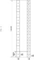
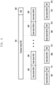
- FIG. 1 is a diagram illustrating the basic structure of a time-frequency domain, which is a radio resource domain of a 5G system.
- the horizontal axis represents time domain and the vertical axis represents frequency domain.
- the basic unit of resources in the time and frequency domains is a resource element (RE) 101, which may be defined as one orthogonal frequency division multiplexing (OFDM) symbol (or discrete Fourier transform spread OFDM (DFT-s-OFDM) symbol) 102 on the time axis and one subcarrier 103 on the frequency axis.
- OFDM orthogonal frequency division multiplexing
- DFT-s-OFDM discrete Fourier transform spread OFDM
- N sc RB e.g., 12
- consecutive REs in the frequency domain may configure one resource block (RB) 104.
- RB resource block
- N symb subframe consecutive OFDM symbols in the time domain may configure one subframe 110.
- FIG. 2 is a diagram illustrating a slot structure considered in a 5G system.
- FIG. 2 illustrates an example of structures of a frame 200, a subframe 201, and a slot 202.
- One frame 200 may be defined as 10ms.
- One subframe 201 may be defined as 1ms, and thus one frame 200 may consist of a total of 10 subframes 201.
- One subframe 201 may consist of one or a plurality of slots 202 and 203, and the number of slots 202 and 203 per one subframe 201 may vary according to ⁇ (204, 205) which is a configured value for the subcarrier spacing.
- N slot subframe , ⁇ and N slot frame , ⁇ according to each subcarrier spacing configuration ⁇ may be defined in Table 1 below. [Table 1] ⁇ N symb slot N slot frame , ⁇ N slot subframe , ⁇ 0 14 10 1 1 14 20 2 2 14 40 4 3 14 80 8 4 14 170 17 5 14 320 32
- DMRS demodulation reference signal
- the DMRS may consist of a plurality of DMRS ports, and each port maintains orthogonality so as not to interfere with each other by using code division multiplexing (CDM) or frequency division multiplexing (FDM).
- CDM code division multiplexing
- FDM frequency division multiplexing
- the terms for the DMRS may be expressed in other terms depending on the user's intention and the purpose of using the reference signal. More specifically, the term DMRS is only presented as a specific example to easily explain the technical content of the disclosure and help understanding of the disclosure, and is not intended to limit the scope of the disclosure. That is, it is obvious to those of ordinary skill in the art that the technical idea of the disclosure may be implemented in reference signals as well.
- FIG. 3 is a diagram illustrating DMRS patterns (type1 and type2) used for communication between a base station and a UE in a 5G system.
- DMRS patterns may be supported. Two DMRS patterns are specifically illustrated in FIG. 3 .
- 301 and 302 represent DMRS type 1, where 301 represents a one-symbol pattern and 302 represents a two-symbol pattern.
- DMRS type 1 of 301 and 302 in FIG. 3 is a DMRS pattern with a comb 2 structure and may be composed of two CDM groups, and different CDM groups may be FDM.
- two DMRS ports may be distinguished by applying CDM in frequency to the same CDM group, and accordingly, a total of four orthogonal DMRS ports may be configured.
- 301 of FIG. 3 illustrates the DMRS port ID mapped to each CDM group (in the case of downlink, the DMRS port ID is displayed by adding +1000 to the illustrated number).
- four DMRS ports may be distinguished by applying CDM in time/frequency to the same CDM group, and accordingly, a total of eight orthogonal DMRS ports may be configured.
- 302 of FIG. 3 illustrates the DMRS port ID mapped to each CDM group (in the case of downlink, the DMRS port ID is displayed by adding +1000 to the illustrated number).
- DMRS type 2 of 303 and 304 in FIG. 3 is a DMRS pattern with a structure in which frequency domain orthogonal cover codes (FD-OCC) are applied to subcarriers adjacent in frequency and may be composed of three CDM groups, and different CDM groups may be FDM.
- FD-OCC frequency domain orthogonal cover codes
- two DMRS ports may be distinguished by applying CDM in frequency to the same CDM group, and accordingly, a total of six orthogonal DMRS ports may be configured.
- 303 of FIG. 3 illustrates the DMRS port ID mapped to each CDM group (in the case of downlink, the DMRS port ID is displayed by adding +1000 to the illustrated number).
- four DMRS ports may be distinguished by applying CDM in time/frequency to the same CDM group, and accordingly, a total of twelve orthogonal DMRS ports may be configured.
- 304 of FIG. 3 illustrates the DMRS port ID mapped to each CDM group (in the case of downlink, the DMRS port ID is displayed by adding +1000 to the illustrated number).
- two different DMRS patterns (301, 302 or 303, 304 of FIG. 3 ) may be configured, and whether the DMRS pattern is a one-symbol pattern (301, 303) or an adjacent two symbol pattern (302, 304) may also be configured.
- the DMRS pattern is a one-symbol pattern (301, 303) or an adjacent two symbol pattern (302, 304) may also be configured.
- not only DMRS port numbers are scheduled, but also the number of CDM groups scheduled together for PDSCH rate matching may be configured and signaled.
- both DMRS patterns described above in DL and UL may be supported, and in the case of discrete Fourier transform spread OFDM (DFT-S- OFDM), only DMRS type1 among the DMRS patterns described above in UL may be supported.
- additional DMRS may be supported to be configurable. Front-loaded DMRS refers to the first DMRS appearing in the first symbol in time, and Additional DMRS refers to a DMRS appearing in a symbol after the front-loaded DMRS. In the NR system, the number of additional DMRSs may be configured from a minimum of 0 to a maximum of 3.
- the same pattern as the front-loaded DMRS may be assumed. More specifically, when information on whether the DMRS pattern type described above for the front-loaded DMRS is type1 or type2, information on whether the DMRS pattern is a one-symbol pattern or an adjacent two symbol pattern, and information on the number of CDM groups used with DMRS ports is indicated, if an additional DMRS is additionally configured, the additional DMRS may be assumed to be configured with the same DMRS information as the front-loaded DMRS.
- downlink DMRS configuration described above may be configured through RRC signaling as illustrated in Table 2 below.
- uplink DMRS configuration may be configured through RRC signaling as illustrated in Table 3 below.
- FIG. 4 is a diagram illustrating an example of channel estimation using a DMRS received from one PUSCH in a time band in a 5G system.
- the channel estimation may be performed within a corresponding bundling unit, precoding resource block group (PRG), by using PRB bundling linked to a system band in a frequency band.
- PRG precoding resource block group
- the channel estimation may be performed by assuming that only a DMRS received from one PUSCH has the same precoding.
- the base station may configure a table for time domain resource allocation information for a physical downlink shared channel (PDSCH) and a physical uplink shared channel (PUSCH) to the UE through higher signaling (e.g., RRC signaling).
- PDSCH physical downlink shared channel
- PUSCH physical uplink shared channel
- the time domain resource allocation information may include, for example, PDCCH-to-PDSCH slot timing (corresponds to the time interval in units of slots between the time when the PDCCH is received and the time when the PDSCH scheduled by the received PDCCH is transmitted, denoted as K0) or PDCCH-to-PUSCH slot timing (corresponds to the time interval in units of slots between the time when the PDCCH is received and the time when the PUSCH scheduled by the received PDCCH is transmitted, denoted as K2), information on the location and length of a start symbol in which PDSCH or PUSCH is scheduled within a slot, PDSCH or PUSCH mapping type, and the like.
- time domain resource allocation information for PDSCH may be configured to the UE through an RRC signal as illustrated in Table 4 below.
- time domain resource allocation information for PUSCH may be configured to the UE through an RRC signal as illustrated in Table 5 below.
- the base station may transmit one of the table entries for the time domain resource allocation information to the UE through L1 signaling (e.g., downlink control information (DCI)) (for example, it may be indicated by the 'time domain resource allocation' field in DCI).
- DCI downlink control information
- the UE may obtain time domain resource allocation information for the PDSCH or PUSCH based on the DCI received from the base station.
- the PUSCH transmission may be dynamically scheduled by a UL grant in DCI or may be operated by configured grant Type 1 or Type 2.
- the dynamic scheduling for PUSCH transmission for example, may be indicated by DCI format 0_0 or 0_1.
- the grant Type 1 PUSCH transmission may be configured semi-statically through reception of configuredGrantConfig including the rrc-ConfiguredUplinkGrant of [Table 6] through higher signaling without receiving UL grant in DCI.
- the configured grant Type 2 PUSCH transmission may be scheduled semi-continuously by UL grant in DCI after reception of configuredGrantConfig that does not include the rrc-ConfiguredUplinkGrant of [Table 6] through higher signaling.
- parameters applied to the PUSCH transmission may be applied through configuredGrantConfig that is the higher signaling of [Table 6] except for specific parameters (e.g., dataScramblingIdentityPUSCH, txConfig, codebookSubset, maxRank, scaling of UCI-OnPUSCH, and the like) provided by pusch-Config, which is the higher signaling, of [Table 7].
- pusch-Config which is the higher signaling, of [Table 7].
- the UE may apply tp-pi2BPSK in pusch-Config of [Table 7] to PUSCH transmission operated by the configured grant.
- the DMRS antenna port for PUSCH transmission may be the same as the antenna port for SRS transmission.
- the PUSCH transmission may follow a codebook-based transmission method and a non-codebook-based transmission method, respectively, depending on whether the value of txConfig in pusch-Config of [Table 7], which is higher signaling, is 'codebook' or 'nonCodebook'.
- the PUSCH transmission may be dynamically scheduled through DCI format 0_0 or 0_1 and may be semi-statically configured by the configured grant.
- the UE may perform beam configuration for PUSCH transmission by using a pucch-spatialRelationInfoID corresponding to the UE-specific (dedicated) PUCCH resource having the lowest ID within the uplink bandwidth part (BWP) activated in the serving cell.
- the PUSCH transmission may be performed based on a single antenna port.
- the UE may not expect scheduling for PUSCH transmission through DCI format 0_0 within the BWP in which the PUCCH resource including the pucch-spatialRelationInfo is not configured. If the UE has not received configured txConfig in pusch-Config of [Table 7], the UE may not expect to be scheduled with DCI format 0_1.
- the codebook-based PUSCH transmission may be dynamically scheduled through DCI format 0_0 or 0_1, and may operate semi-statically by a configured grant.
- the UE may determine a precoder for PUSCH transmission based on SRS resource indicator (SRI), the transmission precoding matrix indicator (TPMI), and the transmission rank (the number of PUSCH transmission layers).
- SRI SRS resource indicator
- TPMI transmission precoding matrix indicator
- the SRI may be given through a field SRS resource indicator in the DCI or may be configured through srs-ResourceIndicator which is higher signaling.
- the UE may receive at least one configured SRS resource and, as an example, up to two configured SRS resources.
- the SRS resource indicated by the corresponding SRI may refer to an SRS resource corresponding to the SRI among SRS resources transmitted before the PDCCH including the corresponding SRI.
- TPMI and transmission rank may be given through field precoding information and number of layers in DCI, or may be configured through precodingAndNumberOfLayers, which is a higher signaling. TPMI may be used to indicate the precoder applied to PUSCH transmission.
- the precoder to be used for PUSCH transmission may be selected from an uplink codebook having the same number of antenna ports as the nrofSRS-Ports value in SRS-Config, which is a higher signaling.
- the UE may determine the codebook subset based on the TPMI and the codebookSubset within the push-Config, which is the higher signaling.
- the codebookSubset in push-Config which is the higher signaling, may be configured to one of 'fullyAndPartialAndNonCoherent', 'partialAndNonCoherent', or 'nonCoherent' based on UE capability reported by the UE to the base station.
- the UE may not expect the value of the higher signaling codebookSubset to be configured to 'fullyAndPartialAndNonCoherent'.
- the UE may not expect the value of the higher signaling codebookSubset to be configured to 'fullyAndPartialAndNonCoherent' or 'partialAndNonCoherent'.
- the UE may not expect the value of codebookSubset, which is the higher signaling, to be configured to 'partialAndNonCoherent'.
- the UE may receive one SRS resource set configured in which the value of the usage in the SRS-resource set, which is the higher signaling, is configured to 'codebook', and one SRS resource within the SRS resource set may be indicated through the SRI. If multiple SRS resources are configured within the SRS resource set in which the usage value in the SRS-resource set, which is the higher signaling, is configured to 'codebook', the UE may expect that the value of nrofSRS-Ports in the SRS-resource, which is the higher signaling, is configured to be the same for all SRS resources.
- the UE may transmit one or a plurality of SRS resources included in the SRS resource set in which the value of usage is configured to 'codebook' to the base station according to upper level signaling, and the base station may select one of the SRS resources transmitted by the UE and instruct the UE to perform PUSCH transmission by using the transmission beam information of the corresponding SRS resource.
- the SRI is used as information on selecting an index of one SRS resource and may be included in the DCI.
- the base station may include information indicating the TPMI and rank to be used by the UE for PUSCH transmission in the DCI for transmission. The UE may perform PUSCH transmission by applying the TPMI indicated based on the transmission beam of the corresponding SRS resource and the precoder indicated by the rank by using the SRS resource indicated by the SRI.
- the non-codebook-based PUSCH transmission may be dynamically scheduled through DCI format 0_0 or 0_1, or may operate semi-statically by a configured grant.
- the UE may receive the non-codebook-based PUSCH transmission scheduled through DCI format 0 1.
- the UE may receive a configured non-zero power (NZP) CSI-RS resource related to one SRS resource set.
- the UE may perform calculation on the precoder for SRS transmission through measurement of the configured NZP CSI-RS resource related to the SRS resource set. If the difference between the last received symbol of the aperiodic NZP CSI-RS resource related to the SRS resource set and the first symbol of the aperiodic SRS transmission in the UE is less than specific symbols (e.g., 42 symbols), the UE may not expect information on the precoder for SRS transmission to be updated.
- specific symbols e.g. 42 symbols
- the NZP CSI-RS related to the SRS-ResourceSet may be indicated by the SRS request, which is a field in DCI format 0_1 or 1_1.
- the NZP CSI-RS related to the SRS-ResourceSet is an aperiodic NZP CSI-RS resource, and when the value of the field SRS request in DCI format 0_1 or 1_1 is not '00', it may indicate that the NZP CSI-RS related to the SRS-ResourceSet exists. In this case, the corresponding DCI should not indicate cross carrier or cross BWP scheduling.
- the corresponding NZP CSI-RS may be located in the slot in which the PDCCH including the SRS request field is transmitted.
- the TCI states configured in the scheduled subcarrier may not be configured to QCL-TypeD.
- the NZP CSI-RS related to the SRS resource set may be indicated through the associatedCSI-RS in the SRS-ResourceSet, which is the higher signaling.
- the UE may not expect that spatialRelationInfo, which is the higher signaling for SRS resource, and associatedCSI-RS in SRS-ResourceSet, which is the higher signaling, are configured together.
- the UE may determine the precoder to be applied to PUSCH transmission and the transmission rank based on the SRI indicated by the base station.
- the SRI may be indicated through a field SRS resource indicator in the DCI or may be configured through srs-ResourceIndicator, which is the higher signaling.
- the SRS resource indicated by the corresponding SRI may refer to the SRS resource corresponding to the SRI among the SRS resources transmitted before the PDCCH including the corresponding SRI.
- the UE may use one or a plurality of SRS resources for SRS transmission, and the maximum number of SRS resources capable of simultaneous transmission in the same symbol in one SRS resource set may be determined by the UE capability reported by the UE to the base station. In this case, the SRS resources simultaneously transmitted by the UE may occupy the same RB.
- the UE may configure one SRS port for each SRS resource. Only one SRS resource set in which the value of usage in the SRS-ResourceSet, which is the higher signaling, may be configured to 'nonCodebook', and up to four SRS resources for non-codebook-based PUSCH transmission may be configured.
- the base station may transmit one NZP-CSI-RS related to the SRS resource set to the UE, and the UE may calculate a precoder to be used when transmitting one or a plurality of SRS resources in the corresponding SRS resource set based on the result measured when receiving the corresponding NZP-CSI-RS.
- the UE may apply the calculated precoder when transmitting one or a plurality of SRS resources in the SRS resource set in which usage is configured to 'nonCodebook' to the base station, and the base station may select one or a plurality of SRS resources among received one or a plurality of SRS resources.
- the SRI indicates an index capable of representing one or a combination of a plurality of SRS resources, and the SRI may be included in the DCI.
- the number of SRS resources indicated by the SRI transmitted by the base station may be the number of transmission layers of the PUSCH, and the UE may transmit the PUSCH by applying the precoder applied to the SRS resource transmission to each layer.
- the UE may not perform PUSCH transmission in the slot where the corresponding symbol is located.
- the 5G system supports two types, PUSCH repeated transmission type A and PUSCH repeated transmission type B, as repeated transmission methods of an uplink data channel.
- the UE may be configured with either PUSCH repetitive transmission type A or B through higher layer signaling.
- FIG. 5 is a diagram illustrating an example of PUSCH repeated transmission type B in a 5G system.
- the UE may configure the frame structure of time division duplexing (TDD) to 3 downlink slots, 1 special/flexible slot, and 1 uplink slot.
- TDD time division duplexing
- the special/flexible slot consists of 11 downlink symbols and 3 uplink symbols
- the initial transmission slot is the third in the second uplink transmission
- the RV of the PUSCH of the first resource 504 actually transmitted is 0, the RV of the PUSCH of the second resource 505 actually transmitted is 2, the RV of the PUSCH of the third resource 506 actually transmitted is 3, and the RV of the PUSCH of the fourth resource 507 actually transmitted is 1.
- PUSCHs with RV 0 and RV 3 may be decoded by themselves, and in the case of the first resource 504 and the third resource 506, because the PUSCH is transmitted only in 3 symbols much less than actually configured symbol length (14 symbols), the bit lengths 508 and 510 to be rate-matched are less than the bit lengths 509 and 511 calculated by the configuration.
- FIG. 6 is a diagram illustrating an example of a process in which one transport block (TB) is divided into several code blocks (CBs) and a CRC is added in a 5G communication system.
- a CRC 602 may be added to the end or front of one transport block (TB) 601 to be transmitted in uplink or downlink.
- the CRC 602 may have 17 bits, 25 bits, a pre-fixed number of bits, or a variable number of bits according to channel conditions, etc., and may be used to determine whether channel coding is successful.
- a block in which the CRC 602 is added to the TB 601 may be divided into several code blocks (CBs) 603, 604, 605, and 606.
- the maximum size of the code block (CB) may be pre-determined and divided, and in this case, the last code block (CB) 606 may have a smaller size than the other code blocks 603, 604, and 605.
- CRCs 611, 611, 612, and 613 may be added to the code block (CB) 607, 608, 609, and 610, respectively.
- the CRC may have 17 bits, 24 bits, or a pre-fixed number of bits, and may be used to determine whether channel coding is successful.
- aA-1 , CRC p1 , p2 , ... pL-1 may determine p1 , p2 , ... pL-1 by dividing a0 D A+23 + a1 D A+22 +... aA-1 D 24 + p0 D 23 + p1 D 22 +... p22 D 1 + p23 by gCRC24A(D) so that the remainder is 0.
- the CRC length L is assumed to be 24 as an example, but the CRC length L may be determined to be various lengths such as 12, 17, 24, 32, 40, 48, and 64.
- the TB+CRC may be divided into N CBs 603, 604, 605, and 606.
- CRCs 611, 612, 613, and 614 may be added to each of the divided CBs 603, 604, 605, and 606.
- the CRC added to the CB may have a different length from when generating the CRC added to the TB, or a different cyclic generator polynomial may be used for generating the CRC.
- the CRC 602 added to the TB and the CRCs 611, 612, 613, and 614 added to the code block (CB) may be omitted depending on the type of code block (CB) to be applied to the code block (CB).
- CRCs 611, 612, 613, and 614 to be inserted for each code block may be omitted.
- the CRCs 611, 612, 613, and 614 may be added to the code block (CB) as it is.
- CRC may be added or omitted even when polar codes are used.
- the maximum length of one code block (CB) may be determined according to the type of channel coding applied to the TB to be transmitted, and according to the maximum length of Code Block (CB), TB and CRC added to TB may be divided into code blocks.
- a CRC for CB is added to the divided CB, the data bits and CRC of the CB are encoded with a channel code and coded bits are determined, and the number of bits to be rate-matched (RM) is determined as promised in advance for each coded bit.
- N ′ RE which is the number of REs allocated to PUSCH mapping in one PRB in the allocated resource is calculated.
- N ′ RE may be calculated as N sc RB ⁇ N symb sh ⁇ N DMRS PRB ⁇ N oh PRB .
- N sc RB may be 12
- N symb sh may indicate the number of OFDM symbols allocated to the PUSCH.
- N DMRS PRB is the number of REs in one PRB occupied by DMRSs of the same CDM group.
- N oh PRB is the number of REs occupied by overhead in one PRB configured by higher signaling, and may be configured to one of 0, 6, 12, and 18. Then, the total number of REs N RE allocated to the PUSCH may be calculated. N RE is calculated as min 166 N RE ′ ⁇ n PRB , and n PRB represents the number of PRBs allocated to the UE. The number of temporary information bits N info may be calculated as N RE ⁇ R ⁇ Q m ⁇ .
- R is a code rate and Q m is a modulation order, and information on this value may be transmitted by using the MCS bit field of DCI and a prearranged table.
- v is the number of assigned layers.
- TBS may be determined to be the closest value to N info ′ among the values not less than N info ′ in Table 9 below.
- TBS may be determined through the N info ′ value and the following [pseudo-code 1].
- C corresponds to the number of code blocks (CB) included in one TB.
- TBoMS transport block processing over multi-slot
- one transport block (TB) is mapped to a plurality of slots or a plurality of physical channels (e.g., PUSCH) and transmitted, is being discussed.
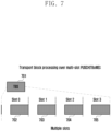
- FIG. 7 is a diagram illustrating an example of physical channel transmission based on transport block processing over multi-slot (TBoMS) according to an embodiment of the disclosure.
- one TB 701 may be allocated to a plurality of slots 702, 703, 704, and 705 and transmitted. Instead of allocating a plurality of small TBs to a plurality of slots, by allocating one TB to a plurality of slots, it is possible to reduce the ratio of CRC bits, obtain a channel coding gain through a low code rate, and improve channel coverage.
- the disclosure proposes procedures in the overall physical layer including DCI format design, TBS determination, code block (CB) division, rate matching, interleaving, CB concatenation, multiplexing, and scrambling for such asymmetric signal processing.
- CB code block
- TBoMS-based PUSCH transmission is described as an example, but this is only for example and does not limit the scope of the disclosure, and it may be applied for any physical channel transmission including PUSCH / PDSCH / PSSCH transmission through predefined / configured or signaling between a base station and a UE.
- slots and PUSCHs will be used interchangeably, but it may be understood that a slot is replaced with a PUSCH or a PUSCH is replaced with a slot on the premise that one PUSCH is transmitted in one slot.
- the disclosure may be equally applied even when a plurality of PUSCHs are transmitted in one slot or one PUSCH is transmitted over a plurality of slots. In this case, one slot should naturally be understood as one PUSCH.
- the operation of a UE or a base station has been described based on the operation of the UE or base station, the base station (or other UE) or the UE may also perform a corresponding operation to support the operation of the corresponding UE or base station.
- each embodiment and signal processing procedure of the disclosure may be applied independently or in combination with one or more of them.
- a physical layer signal processing for TBoMS described in the disclosure may be performed when TBoMS is configured to the UE through TBoMS configuration information.
- the TBoMS configuration information may be configured through any signaling including RRC signaling, system information, MAC or DCI, and may include any information used to perform the physical layer signal processing for TBoMS described below.
- TBoMS configuration information may include information on the number of slots to which one TB is mapped in TBoMS.
- the TBoMS configuration may be a detailed item of PUSCH configuration, and each PUSCH configuration may be a detailed item of BWP configuration. Accordingly, when one cell operates a plurality of BWPs, the TBoMS method may operate only in some BWPs of the cell.
- the TBoMS configuration may be applied to PUSCH in the initial access process, and if transmitted based on dedicated RRC signaling thereafter, the TBoMS configuration may be applied to PUSCH transmission in RRC connected state. If there is no transmission based on system information and transmission is performed based on dedicated RRC signaling, the TBoMS configuration may be applied only to PUSCH transmission in an RRC connected state.
- the number of REs appearing in the following description is a value corresponding to the number of RBs and the number of time resources (number of OFDM symbols) used for PUSCH transmission, and the number of REs may be replaced with the number of RBs and time resources (number of OFDM symbols) used for PUSCH transmission in the following operation based on the number of Res.
- a DCI format design method for TBoMS is disclosed.
- an arbitrary DCI format may be used for TBoMS.
- the UE and the base station may assume that the remaining TBs except for the first TB are always deactivated for a DCI format (e.g., DCI format 0_1 or 1_1, etc.) supporting a plurality of TBs when TBoMS is configured.
- a DCI format e.g., DCI format 0_1 or 1_1, etc.
- the UE may not expect DCI reception indicating activation of the remaining TBs except for the first TB, or if DCI indicating activation of the remaining TBs is received, the UE may not perform PDSCH/PUSCH transmission scheduled by the corresponding DCI or may not perform PDSCH/PUSCH transmissions corresponding to the remaining TBs except for the first one.
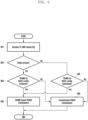
- FIG. 8 is a diagram illustrating an example of TBoMS transmission using a DCI format supporting only one TB according to an embodiment of the disclosure.
- a UE may receive a configured search space for monitoring a DCI format through higher layer signaling through a base station (801).
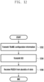
- the UE may determine whether TBoMS is configured, that is, whether TBoMS configuration information is received (802). If TBoMS is configured, the UE may perform monitoring only for a search space related to a DCI format supporting only one TB, for example, DCI format 0 0 or 1_0, among search spaces configured through higher layer signaling (803). If TBoMS is not configured, the UE may monitor an arbitrary DCI format corresponding to the search space in the search space configured through higher layer signaling (804).
- the operation of the UE and the base station when the TBoMS is configured will be described in more detail as follows.
- the UE may monitor a search space for monitoring a DCI format (e.g., DCI format 0_0 or 1_0) supporting only one TB of the configured search space, and may not monitor a search space for monitoring a DCI format (e.g., DCI format 0_1 or 1_1) supporting a plurality of TBs. Accordingly, the UE may monitor only DCI format 0_0 or 1_0 and perform TBoMS-based PDSCH/PUSCH/PSSCH transmission and reception based on this.
- a DCI format e.g., DCI format 0_0 or 1_0
- the base station and the UE may assume that only a search space for monitoring DCI format 00 or 1_0 is configured. That is, when TBoMS is configured, the base station and the UE may not expect that a search space for monitoring other DCI formats other than DCI format 00 or 1_0 is configured. Accordingly, the UE may monitor only DCI format 0_0 or 1_0 based on the configured search space and perform TBoMS-based PDSCH/PUSCH/PSSCH transmission/reception based on this.
- a DCI format for TBoMS or a search space for monitoring the DCI format for TBoMS may be configured in the UE through TBoMS configuration information.
- the UE may monitor only the search space for the DCI format indicated through the TBoMS configuration information among the search spaces configured for the UE.
- the UE may monitor the search space included in the TBoMS configuration information.
- the information included in the TBoMS configuration information may include DCI format 0_0 or 1_0, but is not necessarily limited thereto.
- a UE identifier for DCI format for TBoMS is disclosed.
- the DCI format for TBoMS may include a CRC scrambled with a specific radio network temporary identifier (RNTI).
- RNTI radio network temporary identifier
- a CRC scrambled with C-RNTI cell RNTI
- TC-RNTI temporary C-RNTI
- a CRC scrambled with C-RNTI, TC-RNTI, paging RNTI (P-RNTI), random access RNTI (RA-RNTI), or system information RNTI (SI-RNTI) may be included.
- the TC-RNTI may be used for DCI scheduling Msg3 PUSCH transmission used in the random access procedure.
- the UE and the base station may operate as follows, depending on whether the random access procedure related to the TC-RNTI is an initial access procedure or not.
- TBoMS operation according to DCI reception including a CRC scrambled with TC-RNTI may be performed based on TBoMS configuration information included in RACH-config common included in SIB1.
- TBoMS operation according to DCI reception including a CRC scrambled with TC-RNTI may be performed based on TBoMS configuration information configured through Dedicated RRC.
- TBoMS configuration information configured through Dedicated RRC may be included, for example, in PUSCH-config or RACH-config dedicated.
- a transmission operation of a corresponding preamble (Msg 1) may also be performed through a plurality of slots or RACH Occasion.
- a plurality of preambles (Msg 1) may also be implicitly transmitted.
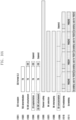
- FIG. 9 is a diagram illustrating TBoMS operation according to reception of DCI including a CRC scrambled with TC-RNTI according to an embodiment of the disclosure.
- the UE when receiving the TC-RNTI-based DCI (901), the UE may determine whether the PUSCH scheduled by the corresponding DCI is for initial access (902). If it is for initial access, the UE may determine whether TBoMS configuration information is included in information configured to common through SIB1 or in RACH configuration information therein (903). If the TBoMS configuration information is included, the UE may perform TBoMS-based PUSCH transmission, that is, PUSCH transmission in a plurality of slots (905). If the TBoMS configuration information is not included, the UE may perform PUSCH transmission in one slot according to a conventional method (906).
- the UE may determine whether TBoMS configuration information is included in RACH configuration information dedicated through RRC (904). If the TBoMS configuration information is included, the UE may perform TBoMS-based PUSCH transmission, that is, PUSCH transmission in a plurality of slots (905). If the TBoMS configuration information is not included, the UE may perform PUSCH transmission in one slot according to a conventional method (906).
- one DCI is related to transmission of a plurality of PUSCHs.
- the following content may be equally applied.
- MCS modulation and coding scheme
- FDRA frequency domain resource allocation
- N may be determined based on TBoMS configuration information
- the TBoMS configuration information may include information directly indicating the number N of MCSs to be used as information for determining N, or information indicating an MCS index, and it may be assumed that the base station and the UE use the MCS corresponding to the index below the indicated index.
- the number of bits for FDRA may be reduced accordingly.
- HARQ-ACK operation in the case of PUSCH, when even one of the plurality of PUSCHs is ACK, it may be determined as ACK (retransmission DCIs for the plurality of PUSCHs corresponding to the DCI are not transmitted), and when all PUSCHs are NACK, NACK may be transmitted (retransmission DCIs for the plurality of PUSCHs corresponding to the DCI are transmitted).
- NACK when even one of the plurality of PUSCHs is NACK, NACK may be transmitted (retransmission DCIs for the plurality of PUSCHs corresponding to the DCI are transmitted), and when all PUSCHs are ACKs, ACKs may be determined (retransmission DCIs for a plurality of PUSCHs corresponding to DCIs are not transmitted).
- the former is suitable when ACK/NACK of the entire TB may be determined through one PUSCH, and the latter is suitable when ACK/NACK for the entire TB may be determined only after receiving all PUSCHs. A detailed description of this may be understood through the following technical description (procedures such as code block division and transmission rate matching).
- the UE may determine the HARQ-ACK feedback bit or HARQ-ACK codebook size to be transmitted by the UE based on downlink assignment indicator (DAI) information included in the DCI in a slot in which HARQ-ACK information determined according to K0, which is the slot information to which the PDSCH is mapped, and the HARQ-ACK feedback timing information K1 value for the PDSCH are transmitted.
- DCI downlink assignment indicator
- a method of determining the DAI value or a method of determining the HARQ-ACK feedback bit or HARQ-ACK codebook size based on the DAI value may be required.
- the DAI may be sequentially increased for each DCI in consideration of the cell as before, and the UE may perform one HARQ-ACK feedback for a plurality of PDSCHs.
- the one HARQ-ACK feedback is based on the decoding result of all PDSCHs, and for example, if any one of a plurality of PDSCHs is ACK, ACK may be transmitted, and if all PDSCHs are NACK, NACK may be transmitted. Alternatively, if even one of the plurality of PDSCHs is NACK, NACK may be transmitted, and if all PDSCHs are ACK, ACK may be transmitted.
- HARQ-ACK transmission timing may be determined based on the reception time of the last PDSCH (e.g., the last symbol of the last PDSCH).
- HARQ-ACK feedback may be performed for each CBG.
- the DAI may be sequentially increased for each DCI in consideration of the cell as before, and the UE may perform HARQ-ACK feedback for each of a plurality of PDSCHs.
- the same HARQ-ACK may be fed back for a plurality of PDSCHs scheduled by DCI indicating one DAI, and the same HARQ-ACK feedback may be fed back as much as the number of PDSCHs (or slots) scheduled through the corresponding DCI. This may be effective when TBs transmitted on a plurality of PDSCHs are the same, but multiplexed control information is different for each PDSCH or is included only in some PDSCHs.
- the DAI may be configured to sequentially increase in consideration of the number of PDSCHs related to each DCI together with the cell, and based on the corresponding DAI value, the UE may perform HARQ-ACK feedback for each of a plurality of PDSCHs.
- DCI format 0_0 may be described as follows.
- DCI format 0_0 is applied to scheduling of a plurality of PUSCHs, each field below will be used for each PUSCH transmission.
- the interpretation method will be explained in detail in the transmission rate matching part.
- it is configured that one same HARQ process number is applied to all PUSCHs.
- the TPC command configures that the same value is applied to all PUSCHs.
- joint channel estimation is not applied and there is a TPC command transmitted at an applicable point after the corresponding TPC command (TPC command transmitted through DCI format 2_2, etc.), this will be applied.
- the existing 4 bits are used as they are, but based on the TDRA list stored in the UE or base station, Dedicated RRC or SIB configuration, etc., information on the number of PUSCHs may be additionally included in addition to the information of the existing TDRA.
- bit size determination relates to bit size determination, and a specific interpretation method will follow the above-mentioned.
- DCI format 0_0 PUSCH scheduling within one cell
- UE identifier C-RNTI or TC-RNTI
- a method for determining a transport block size (TBS) for TBoMS according to an embodiment of the disclosure is disclosed.
- TBS may be determined based on the total number of resource elements (REs) allocated to PUSCHs transmitted in a plurality of slots.
- REs resource elements
- TBS may be determined based on the same number of REs. That is, TBS may be determined based on the number of REs allocated to the PUSCH transmitted in one slot.
- TBS may be determined based on any one of the following methods.
- the TBS determination method based on the above embodiments may be predefined/configured or configured through signaling (RRC, system information, MAC, DCI, ...) between the base station and the UE.
- RRC radio resource control
- MAC media access control
- DCI data convergence protocol
- the TBS determined according to the above embodiments may be determined to be equal to or less than the maximum TBS for TBoMS transmission.
- the base station may adjust or limit parameters used in the TBS calculation process so that the TBS calculated according to the above embodiments is equal to or less than the maximum TBS for TBoMS.
- a UE receiving the DCI designed such that the TBS is calculated to be equal to or less than the maximum TBS may calculate the TBS based on the received DCI.
- the maximum TBS may be configured through signaling between the base station and the UE.
- the maximum TBS may be included in TBoMS configuration information and configured to the UE.
- the UE may not perform PUSCH transmission for the corresponding TB, or may perform PUSCH transmission by using the configured maximum TBS instead of the calculated TBS.
- the maximum TBS for the TBoMS may be configured to one value independent of a modulation order, or the maximum TBS corresponding to each modulation order may be configured.
- the base station and the UE may perform the above-described operation in consideration of the modulation order determined through the MCS field.
- a CRC bit may be attached to the TB having the determined TBS.
- the CRC bit attached to the TB may be 24 bits.
- a code block (CB) division method for TBoMS is disclosed.
- CB segmentation may not be supported in case of TBoMS-based transmission. That is, considering high coding gain in TBoMS, it is preferable to transmit a small-sized TB, and in this case, CB splitting may not occur.
- the base station may design and transmit the DCI to the UE so that the TBS is calculated to be equal to or less than the size required for the CB segmentation.
- the UE may not expect DCI reception that causes TBS to exceed the size required for the CB segmentation. If received, the UE may not perform transmission of the physical channel scheduled by the corresponding DCI.
- the base station or the UE may configure the maximum TBS size for the TBoMS described in the TBS determination method above to be equal to or less than the TBS required for the CB segmentation.
- the base station or the UE may scale the calculated TBS to be equal to or less than the TBS for which CB segmentation is required.
- the base station or the UE may not perform the CB segmentation when TBoMS is configured, regardless of the calculated TBS and the TBS for which CB segmentation is required.
- the CB segmentation may be supported for TBoMS-based transmission.
- the base station and the UE may determine the number of CBs and the size of each CB with reference to TS 38.212 Section 5.2 of Release 15 according to the size of the TBS, and for example, the number of CBs and the size of each CB may be determined based on Table 10 below.
- the number of divided CBs may be equal to the number of slots (or physical channels) for TBoMS or may be determined to be a multiple of the number of slots (or PUSCHs).
- the number of slots for TBoMS may be configured through TBoMS configuration information.
- the same number of CBs may be mapped to and transmitted to each physical channel (e.g., PUSCH). For example, when the number of slots for TBoMS is configured to 4 in PUSCH transmission and the determined number of CBs is 4, one CB may be mapped to each PUSCH of each slot and transmitted.
- PUSCH physical channel
- the CB may be re-divided into the same number or multiple.
- the CB may be re-divided into smaller CBs to match the number of corresponding slots. For example, when the number of slots for TBoMS in PUSCH transmission is configured to 4 and the determined number of CBs is 2, the TB may be re-divided into 4 CBs having smaller sizes.
- the four re-segmented CBs may be transmitted after being mapped one by one to the PUSCH of each slot.
- the CB may be re-divided into smaller or larger CBs to match the number of slots or to be a multiple of the number of slots. For example, when the number of slots for TBoMS in PUSCH transmission is configured to 4 and the determined number of CBs is 6, the TB may be re-divided into 4 CBs having a larger size. The four re-segmented CBs may be transmitted after being mapped one by one to the PUSCH of each slot. As another example, the TB may be re-divided into 8 CBs having a smaller size. The eight re-segmented CBs may be transmitted after being mapped to two PUSCHs of each slot.
- CB segmentation is supported for TBoMS-based transport or when supported or not supported, which methods are used respectively may be predefined/configured or configured through signaling (RRC, system information, MAC, DCI, (7) between the base station and the UE.
- RRC radio resource control
- a CB CRC attachment method for TBoMS is disclosed.
- the CRC attachment operation for the divided CB may be performed according to the method below.
- a 24-bit CRC may be attached to each CB as in the prior art.
- a smaller size CRC bit may be used in the case of TBoMS instead of the conventional 24 bits to minimize redundancy for high coding gain.
- a 16-bit CRC may be attached to each CB, or a CRC of an arbitrary size newly defined in relation to TBoMS may be attached to each CB.
- This embodiment may also include a case in which a 0-bit CRC is used, that is, a separate CRC is not attached even if the CB segmentation is supported.
- the CRC may be attached in units of CBGs instead of each CB.
- whether the CB segmentation is supported, or the CB CRC attachment method for the case where it is supported may be predefined/configured or configured through signaling (RRC, system information, MAC, DCI, ...) between the base station and the UE.
- RRC radio resource control
- the channel coding may be performed on a CB to which a CRC is attached (or, if CB segmentation is not supported, a TB to which a CRC is attached).
- the Channel coding may be performed based on at least one of LDPC codes, polar codes, and simplex codes.
- a rate matching or bit selection method for TBoMS is disclosed.
- An embodiment described below may be applied to a rate matching operation for channel coding based on an LDPC code, a polar code, or a simplex code.
- one rate matching may be performed over the entire number of slots configuration for TBoMS. That is, for bits output through channel coding, rate matching or bit selection may be performed based on the number of REs of all PUSCHs transmitted in slots for TBoMS and the RV indicated by DCI. In this case, bits corresponding to the number of REs of each PUSCH will be sequentially allocated to each PUSCH. This has the same effect as sequentially applying RV to each PUSCH. However, as a method for determining the starting time point of bits allocated to each PUSCH, a method in which the next bit of the bit allocated to the previous PUSCH among all selected bits becomes the starting time point of the bit allocated to the current PUSCH may be applied, rather than the method described in the existing standard.
- rate matching or bit selection may be performed for each slot according to the number configured for TBoMS.
- rate matching or bit selection may be substantially performed only once, and the result of the one-time execution may be equally used for PDSCH/PUSCH transmission in each slot.
- bits according to the same RV may be determined to have the same bit size in the channel coding result.
- rate matching or bit selection may be performed for each RV.
- bits corresponding to each RV in the channel coding result may be determined to have the same bit size.
- the RV value of the PDSCH/PUSCH of each slot may be determined sequentially (e.g., 0 ⁇ 2 ⁇ 3 ⁇ 1, 2 ⁇ 3 ⁇ 1 ⁇ 0 ...) through a modulo formula similar to the PUSCH repetition operation. The order may be determined through RRC signaling.
- rate matching or bit selection may be performed for each number of REs.
- the number of bits corresponding to each bit size determined according to the number of REs in the channel coding result may be determined based on the same RV.
- rate matching or bit selection may be performed for each RE number and RV.
- bits corresponding to each bit size determined according to the number of REs in the channel coding result may be determined through a part corresponding to each RV.
- whether to perform rate matching over all slots or whether to perform rate matching for each slot may be predefined/configured or may be configured through signaling (RRC, system information, MAC, DCI, ...) between the base station and the UE.
- rate matching when rate matching is performed for each slot, whether to use one of the methods described above may be predefined/configured, configured through signaling (RRC, system information, MAC, DCI, ...) between the base station and the UE, or may be switched as needed.
- rate matching may be performed for each CB.
- the RV to be applied for the rate matching for each CB may be determined sequentially (e.g., 0 ⁇ 2 ⁇ 3 ⁇ 1, 2 ⁇ 3 ⁇ 1 ⁇ 0 ...) through a modulo formula similarly to the PUSCH repetition operation, or the same RV value may be used for all CBs.
- the number of bits determined through bit selection in the rate matching step may be determined by considering the number of bits multiplexed in the PUSCH of each slot, which will be described later, and the number of bits of each PUSCH determined through bit selection may be different according to the multiplexing method. For example, when the number of bits determined based on the number of REs allocated to the PUSCH of a specific slot is 120, if there is no UCI multiplexing in the corresponding slot, 120 bits may be output through bit selection. On the other hand, when 16-bit UCI multiplexing is required in the corresponding slot, 104 bits may be output through bit selection by considering bits to be added for the multiplexing.
- An interleaving method for TBoMS according to an embodiment of the disclosure is disclosed.
- the interleaving may be performed on all bits output through rate matching.
- the interleaving when TBoMS is configured, the interleaving may be performed between bits mapped to the same slot (or PUSCH) among bits output through rate matching. In this case, if different CBs are mapped for each PUSCH, the interleaving may be performed only between selected bits corresponding to each CB. Alternatively, if selected bits transmitted on each PUSCH are different even if different CBs are not mapped for each PUSCH, the interleaving may be performed between corresponding selected bits of each PUSCH.
- whether the interleaving for all bits or the slot-based interleaving is performed may be predefined/configured or configured through signaling (RRC, system information, MAC, DCI, ...) between the base station and the UE.
- RRC radio resource control
- MAC media access control
- DCI data convergence protocol
- a CB concatenation method for TBoMS is disclosed. In this paragraph, it is described as CB coupling, but when considering the rate matching or interleaving, it may also be referred to as rate matching block coupling or interleaving block coupling.
- the CB concatenation may be performed according to the method below.
- all bits corresponding to all rate-matched and interleaved CBs are combined, and a signal processing procedure after the CB concatenation may be performed based on the combination of all bits of all the CBs.
- a slot-based CB concatenation may be performed. For example, when two CBs are mapped to each slot, two CBs mapped to the same slot may be combined. If CBs are different for each slot (PUSCH) and the number of CBs mapped per PUSCH is multiple, CB concatenation may be performed between selected bits of CBs corresponding to each PUSCH.
- CB concatenation may be performed between selected bits corresponding to each PUSCH.
- a multiplexing method of a data channel and a control channel for TBoMS is disclosed.
- UCI uplink control information
- SCI sidelink control information
- the entirety of UCI information may be multiplexed based on the same number of bits in all slots, or multiplexed based on an individual number of bits for each slot.
- a part constituting the entire UCI information may be multiplexed based on the same number of bits in all slots, or based on an individual number of bits for each slot.
- all or part of UCI information may be multiplexed and transmitted in part or one rather than all of a plurality of slots. If UCI is multiplexed in one or more partial slots among a plurality of slots, the method according to the previous two examples may be used. The same method may be applied to multiplexing of SCI and PSSCH. Specifically, data and control information may be multiplexed and transmitted according to the following method.
- UCI may be multiplexed with PUSCH and transmitted in a slot configured for TBoMS-based PUSCH transmission based on at least one of the following methods.
- entire channel-coded modulation symbols of UCI may be multiplexed and transmitted in each of the PUSCHs of a plurality of slots.
- the same number of coded modulation symbols may be multiplexed and transmitted in the PUSCH of all slots.
- the calculation of the number of coded modulation symbols for UCI may be performed only once for a plurality of slots.
- the calculation of the number of coded modulation symbols for UCI may utilize information on the number of CBs applied to a specific PUSCH, the number of bits per CB, the number of RBs, and the number of time resources. This is inferred from the information included in the DCI.
- a method of selecting a specific slot is the same as a method described later.
- the information may be an average value for each slot.
- the calculation of the number of coded modulation symbols for UCI is the same as above in that the calculation of the number of coded modulation symbols is performed only once for a plurality of slots, but the information on the number of CBs, the number of bits per CB, the number of RBs, and the number of time resources is information considering the entire PUSCH, and the calculated coded modulation symbols may be equally divided and multiplexed in each slot or differentially divided and multiplexed based on the number of REs for each slot.
- the number of coded modulation symbols individually determined for each PUSCH of each slot may be multiplexed and transmitted.
- the calculation of the number of coded modulation symbols for UCI may be individually performed for each slot, and the number of coded modulation symbols multiplexed in each slot may be the same or different.
- the calculation of the number of coded modulation symbols for UCI may utilize information on the number of CBs applied to each PUSCH, the number of bits per CB, the number of RBs, and the number of time resources.
- all of the channel-coded modulation symbols of the UCI may be multiplexed and transmitted in some (or one) of a plurality of slots.
- UCI may be multiplexed and transmitted only in the PUSCH of the first slot, and only UL-SCH may be transmitted in the remaining slots.
- the PUSCH having the largest number of REs may be selected.
- the PUSCH or its selection condition may be configured by signaling (RRC, system information, MAC, DCI, ...) between the base station and the UE.
- bit selection in the rate matching step may be performed considering the number of bits inserted for the multiplexing. If modulation symbols corresponding to different numbers of bits are multiplexed for each slot, accordingly, the number of bits determined through the bit selection may also vary for each slot.
- the method for performing multiplexing described in the disclosure may be predefined/configured or configured through signaling (RRC, system information, MAC, DCI, ...) between the base station and the UE.
- RRC signaling
- MAC media access control
- DCI data convergence protocol
- a scrambling method for TBoMS is disclosed. Here, it is assumed that the processing of the placeholder bit in the existing standard is the same as in the prior art.
- only one scrambling code (or scrambling sequence) for the scrambling operation may be generated to be applied over all of a plurality of slots, and the scrambling operation may be performed over all slots.
- the scrambling operation may be performed by sequentially mapping bits for data channels (PDSCH/PUSCH/PSSCH) of a plurality of slots from the start of the scrambling code.
- a scrambling operation may be performed by mapping from the next bit to the bits for the data channel of the next slot.
- a scrambling code (or scrambling sequence) for a scrambling operation may be generated for each of a plurality of slots, and the scrambling operation may be performed for each slot.
- data and control information may be multiplexed and transmitted according to the following method.
- One scrambling code (or scrambling sequence) is generated for all of the plurality of slots, and scrambling may be performed based on this.
- a starting point of the scrambling code for each slot of the entire scrambling sequence may be determined based on the number of coded modulation symbols (i.e., the number of REs for actual PDSCH/PUSCH/PSSCH) in the previous slot.
- the starting point of the scrambling code for the first slot may be 0.
- a start point of the scrambling code for each slot in the entire scrambling sequence may be determined based on the number of REs between the start RE of the PDSCH/PUSCH/PSSCH of the previous slot and the start RE of the PDSCH/PUSCH/PSSCH of the current slot. In this case, OFDM symbols not allocated to PDSCH/PUSCH/PSSCH and REs for DMRS may also be included.
- the starting point of the scrambling code for the first slot may be 0.
- a starting point of the scrambling code for each slot of the entire scrambling sequence may be determined based on the slot length and the number of allocated PRBs.
- the starting point of the scrambling code for the first slot may be 0.
- a scrambling code is generated for each slot, and scrambling may be performed based on this.
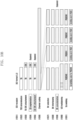
- FIGS. 10A and 10B are diagrams illustrating examples of entire signal processing procedures in a physical layer based on a combination of techniques of the disclosure, respectively.
- FIGS. 10A and 10B will be described assuming one of the various embodiments described in each physical layer signal processing procedure as an example, but this is only for illustrative purposes and does not limit the scope of the disclosure, and may be modified and applied based on a combination of the various embodiments described above.
- specific numerical values used in the description of FIGS. 10A and 10B are also for illustrative purposes only and do not limit the scope of the disclosure.
- TBoMS is configured through TBoMS configuration information.
- a UE may receive DCI format 0_0 for scheduling a PUSCH from a base station (1001).
- the DCI may include information indicating frequency domain resource allocation (FDRA), time domain resource allocation (TDRA), MCS, and RV.
- FDRA, TDRA, MCS, and RV included in one DCI format 0_0 indicate one value through a single field, but this does not limit the scope of the disclosure, and a plurality of fields for indicating information related to PUSCH transmission in a plurality of slots may be included or a plurality of DCIs may be transmitted.
- some fields (TDRA: the number of PUSCHs may be designated) may be modified and newly interpreted.
- a CRC may be attached to the TB corresponding to the determined TBS (1003).
- the CRC attached to the TB may have, for example, 24 bit size.
- Channel coding may be performed on the entire 184 bits to which the CRC is attached to the TB (1006).
- the channel coding may be performed based on LDPC code.
- Rate matching may be performed on the channel-coded bits (1007).
- one rate matching operation is performed over the PUSCH of all slots, and in this case, bit selection may be performed based on channel coded bits according to the RV value indicated through DCI format 0_0.
- RV may be equally applied as a value indicated by DCI for each slot, or may be sequentially determined through a modulo equation.
- the UE may perform bit selection considering UCI bits multiplexed in the PUSCH of a plurality of slots. In this case, if the rate matching operation is performed for each slot or CB in another example, bit selection of different sizes may be performed considering UCI bits multiplexed in each slot.
- Interleaving may be performed on the rate-matched bits (1008). In this example, it is assumed that interleaving is performed once for all rate-matched bits, that is, over the PUSCH of all slots. As another example, interleaving may be performed in units of slots or CBs, and a detailed method refers to the above-described embodiment.
- CB concatenation may also not be performed (1009).
- the CB concatenation may also be performed, and for a detailed method, refer to the above-described embodiment.
- bits for control information may be multiplexed in PUSCH transmission (1010).
- UCI in case of PUSCH transmission
- all UCI bits are multiplexed in each PUSCH in all slots, but UCI bits may be multiplexed in PUSCHs in a plurality of slots in various ways according to the above-described embodiment.
- scrambling may be performed based on a scrambling code (or scrambling sequence) (1011).
- a scrambling code or scrambling sequence
- the scrambling is performed by applying one scrambling code to the PUSCH of all slots as an example, a separate scrambling code may be applied to each slot.
- bits corresponding to the PUSCH of each slot may be sequentially mapped to the determined scrambling code.
- scrambling codes corresponding to multiplexed control information e.g., UCI
- the PUSCH may be transmitted in a plurality of slots through modulation, layer mapping and precoding, resource mapping, and the like.
- a UE may receive DCI format 0_0 for scheduling a PUSCH from a base station (1051).
- the DCI may include information indicating frequency domain resource allocation (FDRA), time domain resource allocation (TDRA), MCS, and RV.
- FDRA, TDRA, MCS, and RV included in one DCI format 0_0 indicate one value through a single field, but this does not limit the scope of the disclosure, and a plurality of fields for indicating information related to PUSCH transmission in a plurality of slots may be included or a plurality of DCIs may be transmitted.
- some fields (TDRA: the number of PUSCHs may be designated) may be modified and newly interpreted.
- a CRC may be attached to the TB corresponding to the determined TBS (1053).
- the CRC attached to the TB may have, for example, 24 bit size.
- Channel coding may be performed on the entire 184 bits to which the CRC is attached to the TB (1056).
- the channel coding may be performed based on LDPC code.
- Rate matching may be performed on the channel-coded bits (1057).
- the rate matching is performed for each PUSCH of each slot, and in this case, it is configured that the RV value indicated through DCI format 0_0 is equally applied to all PUSCH rate matching.
- RV may be determined sequentially through a modulo equation.
- the rate matching is performed for each PUSCH of a slot, the result of bit selection for each slot may vary according to the number of REs or RV value of each PUSCH.
- the UE may perform bit selection by considering UCI bits multiplexed in the PUSCH of each slot.
- bit selection of different sizes may be performed considering the UCI bits multiplexed in each slot.
- Interleaving may be performed on the rate-matched bits (1058). In this example, interleaving is performed in units of slots or CBs. A detailed method refers to the above-described embodiment.
- CB concatenation may also not be performed (1059).
- the CB concatenation may also be performed, and for a detailed method, refer to the above-described embodiment.
- bits for control information may be multiplexed in PUSCH transmission (1060).
- UCI in case of PUSCH transmission
- all UCI bits are multiplexed in one selected PUSCH, but UCI bits may be multiplexed in PUSCHs in a plurality of slots in various ways according to the above-described embodiment.
- scrambling may be performed based on a scrambling code (or scrambling sequence) (1061).
- a scrambling code or scrambling sequence
- a separate scrambling code may be applied for each slot.
- the scrambling codes applied to each slot are substantially the same.
- the length of the scrambling code may be different according to the number of bits allocated to each PUSCH.
- the PUSCH may be transmitted in a plurality of slots through modulation, layer mapping and precoding, resource mapping, and the like.
- FIG. 11 is a diagram illustrating a UE operation for TBoMS PUSCH transmission according to an embodiment of the disclosure.
- the UE may receive TBoMS configuration information for TBoMS configuration from a base station (1102).
- the TBoMS configuration information may be configured through arbitrary signaling including RRC signaling, system information, MAC or DCI, and may include arbitrary information used to perform TBoMS physical layer signal processing.
- the TBoMS configuration information may include information on the number of slots to which one TB is mapped in TBoMS.
- the UE may receive DCI for scheduling the PUSCH of a plurality of slots from the base station (1104).
- the corresponding DCI reception operation may refer to the embodiment described above through [DCI format].
- the UE may perform a physical layer signal processing procedure according to embodiments of the disclosure to transmit a PUSCH in a plurality of slots based on the TBoMS configuration information and the received DCI (1106). Thereafter, the UE may transmit the PUSCH of a plurality of slots to the base station (1108).
- FIG. 11 has described the TBoMS PUSCH transmission of the UE as an example, this may be equally applied to reception of the PDSCH or transmission and reception of the PSSCH.
- FIG. 12 is a diagram illustrating a base station operation for TBoMS PUSCH reception according to an embodiment of the disclosure.
- the base station may transmit TBoMS configuration information for TBoMS configuration to a UE (1202).
- the TBoMS configuration information may be configured through arbitrary signaling including RRC signaling, system information, MAC or DCI, and may include arbitrary information used to perform TBoMS physical layer signal processing.
- the TBoMS configuration information may include information on the number of slots to which one TB is mapped in TBoMS.
- the base station may transmit DCI for scheduling the PUSCH of a plurality of slots to the UE (1204).
- the UE may perform a physical layer signal processing procedure according to embodiments of the disclosure to transmit a PUSCH in a plurality of slots based on the TBoMS configuration information and the received DCI, and the base station may receive the PUSCH of a plurality of slots from the UE (1206).
- FIG. 12 has described the TBoMS PUSCH reception of the base station as an example, this may be equally applied to transmission of the PDSCH.
- FIG. 13 is a diagram illustrating the structure of a UE according to an embodiment of the disclosure.
- the UE of the disclosure may include a UE receiver 1300, a UE transmitter unit 1304, and a UE processor 1302.
- the UE receiver 1300 and the UE transmitter 1304 may be collectively referred to as a transceiver in an embodiment of the disclosure.
- the transceiver may transmit/receive signals with the base station.
- the signal may include control information and data.
- the transceiver may include an RF transmitter for up-converting and amplifying the frequency of a transmitted signal, and an RF receiver for low-noise amplifying a received signal and down-converting the frequency of the signal.
- the transceiver may receive a signal through a wireless channel, output the signal to the UE processor 1302, and transmit the signal output from the UE processor 1302 through the wireless channel.
- the UE processor 1302 may control a series of processes so that the UE may operate according to the above-described embodiment of the disclosure.
- FIG. 14 is a diagram illustrating the structure of a base station according to an embodiment of the disclosure.
- the base station of the disclosure may include a base station receiver 1401, a base station transmitter unit 1405, and a base station processor 1403.
- the base station receiver 1401 and the base station transmitter unit 1405 may be collectively referred to as a transceiver in an embodiment of the disclosure.
- the transceiver may transmit/receive signals with the UE.
- the signal may include control information and data.
- the transceiver may include an RF transmitter for up-converting and amplifying the frequency of a transmitted signal, and an RF receiver for low-noise amplifying a received signal and down-converting the frequency of the signal.
- the transceiver may receive a signal through a wireless channel, output the signal to the base station processor 1403, and transmit the signal output from the base station processor 1403 through the wireless channel.
- the base station processor 1403 may control a series of processes so that the base station may operate according to the above-described embodiment of the disclosure.
Landscapes
- Engineering & Computer Science (AREA)
- Signal Processing (AREA)
- Computer Networks & Wireless Communication (AREA)
- Mobile Radio Communication Systems (AREA)
Applications Claiming Priority (2)
| Application Number | Priority Date | Filing Date | Title |
|---|---|---|---|
| KR1020210060322A KR20220152859A (ko) | 2021-05-10 | 2021-05-10 | 무선 통신 시스템에서 복수 슬롯을 통한 신호 전송 방법 및 장치 |
| PCT/KR2022/005725 WO2022239998A1 (fr) | 2021-05-10 | 2022-04-21 | Procédé et dispositif pour émettre un signal à travers une pluralité de créneaux dans un système de communication sans fil |
Publications (2)
| Publication Number | Publication Date |
|---|---|
| EP4322679A1 true EP4322679A1 (fr) | 2024-02-14 |
| EP4322679A4 EP4322679A4 (fr) | 2024-11-06 |
Family
ID=84028584
Family Applications (1)
| Application Number | Title | Priority Date | Filing Date |
|---|---|---|---|
| EP22807646.9A Pending EP4322679A4 (fr) | 2021-05-10 | 2022-04-21 | Procédé et dispositif pour émettre un signal à travers une pluralité de créneaux dans un système de communication sans fil |
Country Status (4)
| Country | Link |
|---|---|
| US (1) | US20240098714A1 (fr) |
| EP (1) | EP4322679A4 (fr) |
| KR (1) | KR20220152859A (fr) |
| WO (1) | WO2022239998A1 (fr) |
Cited By (1)
| Publication number | Priority date | Publication date | Assignee | Title |
|---|---|---|---|---|
| US20220369307A1 (en) * | 2020-08-05 | 2022-11-17 | Zte Corporation | System and method for resource allocation |
Families Citing this family (4)
| Publication number | Priority date | Publication date | Assignee | Title |
|---|---|---|---|---|
| US12568508B2 (en) * | 2020-04-08 | 2026-03-03 | Qualcomm Incorporated | Multiple DCIS transmitted over PDSCH |
| KR20240071118A (ko) | 2022-11-15 | 2024-05-22 | 에스케이하이닉스 주식회사 | 메모리 장치 및 이의 동작 방법 |
| US20250286657A1 (en) * | 2024-03-06 | 2025-09-11 | Qualcomm Incorporated | Configuring a codeblock size based on device capability |
| US20250324428A1 (en) * | 2024-04-15 | 2025-10-16 | Qualcomm Incorporated | Transport block size and soft buffer management for shared channel transmissions |
Family Cites Families (2)
| Publication number | Priority date | Publication date | Assignee | Title |
|---|---|---|---|---|
| EP3925120A4 (fr) * | 2019-02-15 | 2022-07-27 | ZTE Corporation | Schéma d'indication de ressource pour transmissions répétées |
| CN113785527B (zh) * | 2019-05-03 | 2024-09-27 | Lg电子株式会社 | 发送pusch的方法、用户设备、设备和存储介质以及接收pusch的方法和基站 |
-
2021
- 2021-05-10 KR KR1020210060322A patent/KR20220152859A/ko active Pending
-
2022
- 2022-04-21 WO PCT/KR2022/005725 patent/WO2022239998A1/fr not_active Ceased
- 2022-04-21 EP EP22807646.9A patent/EP4322679A4/fr active Pending
-
2023
- 2023-11-09 US US18/506,082 patent/US20240098714A1/en active Pending
Cited By (2)
| Publication number | Priority date | Publication date | Assignee | Title |
|---|---|---|---|---|
| US20220369307A1 (en) * | 2020-08-05 | 2022-11-17 | Zte Corporation | System and method for resource allocation |
| US12219584B2 (en) * | 2020-08-05 | 2025-02-04 | Zte Corporation | System and method for resource allocation |
Also Published As
| Publication number | Publication date |
|---|---|
| KR20220152859A (ko) | 2022-11-17 |
| US20240098714A1 (en) | 2024-03-21 |
| WO2022239998A1 (fr) | 2022-11-17 |
| EP4322679A4 (fr) | 2024-11-06 |
Similar Documents
| Publication | Publication Date | Title |
|---|---|---|
| CN112740603B (zh) | 无线通信系统中发送和接收物理层信道的方法和装置 | |
| KR102425072B1 (ko) | 무선 통신 시스템에서 단말의 전력 소모 감소를 위한 하향링크 제어채널 설정 방법 및 장치 | |
| EP3892049B1 (fr) | Procédés et appareils d'émission/réception d'informations de commande dans un système de communication sans fil | |
| KR102868523B1 (ko) | 무선 통신 시스템에서 비승인 기반 데이터 전송 방법 및 장치 | |
| US12568347B2 (en) | Method and apparatus for transmission and reception of groupcast and broadcast data in wireless cellular communication system | |
| EP3855663B1 (fr) | Procédé et dispositif de transmission et de réception de signaux dans un système de communication sans fil | |
| EP4322679A1 (fr) | Procédé et dispositif pour émettre un signal à travers une pluralité de créneaux dans un système de communication sans fil | |
| EP3771120A1 (fr) | Procédé et dispositif de transmission et de réception d'informations de commande dans un système de communication cellulaire sans fil | |
| KR20220129270A (ko) | 무선 통신 시스템에서 상향링크 채널 전송을 위한 방법 및 장치 | |
| KR20190014915A (ko) | 무선 통신 시스템에서 하향링크 제어정보를 송수신하는 방법 및 장치 | |
| KR20220101603A (ko) | 무선 셀룰라 통신 시스템에서 상향링크 제어 채널의 반복 전송 방법 및 장치 | |
| KR20190083707A (ko) | 무선 통신 시스템에서 서로 다른 상향 제어 정보를 전송하기 위한 방법 및 장치 | |
| JP2025000846A (ja) | 集積回路 | |
| EP3958637B1 (fr) | Procédé et dispositif de transmission d'informations de commande dans un système de communication sans fil | |
| US11665702B2 (en) | Method and device for transmitting downlink control information for supporting non-orthogonal multiple access in wireless communication system | |
| KR102408035B1 (ko) | 무선 통신 시스템에서 복수의 전송시간구간 운용 방법 및 장치 | |
| EP4113881A1 (fr) | Procédé et dispositif de transmission et de réception de signal de référence dans un système de communication sans fil | |
| KR20180099412A (ko) | 무선 셀룰라 통신 시스템에서 제어 및 데이터 신호의 사용자 구분 방법 및 장치 | |
| EP4024745A1 (fr) | Procédé et appareil de transmission de données pour la communication sans fil | |
| KR102309741B1 (ko) | 무선 셀룰라 통신 시스템에서 상향링크 전력제어 방법 및 장치 | |
| US12160312B2 (en) | Method and apparatus for transmitting and receiving data channels in wireless communication system | |
| KR20220137473A (ko) | 무선 통신 시스템에서 상향링크 채널 전송을 위한 방법 및 장치 | |
| KR20190053748A (ko) | 무선 통신 시스템에서 제어 정보를 송수신하는 방법 및 장치 | |
| US20240364459A1 (en) | Method and apparatus for transmitting uplink channel in wireless communication system | |
| US20240323964A1 (en) | Method and device for uplink channel transmission in wireless communication system |
Legal Events
| Date | Code | Title | Description |
|---|---|---|---|
| STAA | Information on the status of an ep patent application or granted ep patent |
Free format text: STATUS: THE INTERNATIONAL PUBLICATION HAS BEEN MADE |
|
| PUAI | Public reference made under article 153(3) epc to a published international application that has entered the european phase |
Free format text: ORIGINAL CODE: 0009012 |
|
| STAA | Information on the status of an ep patent application or granted ep patent |
Free format text: STATUS: REQUEST FOR EXAMINATION WAS MADE |
|
| 17P | Request for examination filed |
Effective date: 20231110 |
|
| AK | Designated contracting states |
Kind code of ref document: A1 Designated state(s): AL AT BE BG CH CY CZ DE DK EE ES FI FR GB GR HR HU IE IS IT LI LT LU LV MC MK MT NL NO PL PT RO RS SE SI SK SM TR |
|
| DAV | Request for validation of the european patent (deleted) | ||
| DAX | Request for extension of the european patent (deleted) | ||
| A4 | Supplementary search report drawn up and despatched |
Effective date: 20241008 |
|
| RIC1 | Information provided on ipc code assigned before grant |
Ipc: H04L 5/00 20060101ALI20241001BHEP Ipc: H04W 72/04 20230101ALI20241001BHEP Ipc: H04W 72/12 20230101AFI20241001BHEP |