EP4322716A1 - Boîtier pour circuit électrique et procédé de fabrication associé - Google Patents
Boîtier pour circuit électrique et procédé de fabrication associé Download PDFInfo
- Publication number
- EP4322716A1 EP4322716A1 EP23190575.3A EP23190575A EP4322716A1 EP 4322716 A1 EP4322716 A1 EP 4322716A1 EP 23190575 A EP23190575 A EP 23190575A EP 4322716 A1 EP4322716 A1 EP 4322716A1
- Authority
- EP
- European Patent Office
- Prior art keywords
- housing
- transverse direction
- side walls
- heat sinks
- rear wall
- Prior art date
- Legal status (The legal status is an assumption and is not a legal conclusion. Google has not performed a legal analysis and makes no representation as to the accuracy of the status listed.)
- Granted
Links
Images


Classifications
-
- H—ELECTRICITY
- H05—ELECTRIC TECHNIQUES NOT OTHERWISE PROVIDED FOR
- H05K—PRINTED CIRCUITS; CASINGS OR CONSTRUCTIONAL DETAILS OF ELECTRIC APPARATUS; MANUFACTURE OF ASSEMBLAGES OF ELECTRICAL COMPONENTS
- H05K5/00—Casings, cabinets or drawers for electric apparatus
- H05K5/10—Casings, cabinets or drawers for electric apparatus comprising several parts forming a closed casing
-
- H—ELECTRICITY
- H05—ELECTRIC TECHNIQUES NOT OTHERWISE PROVIDED FOR
- H05K—PRINTED CIRCUITS; CASINGS OR CONSTRUCTIONAL DETAILS OF ELECTRIC APPARATUS; MANUFACTURE OF ASSEMBLAGES OF ELECTRICAL COMPONENTS
- H05K5/00—Casings, cabinets or drawers for electric apparatus
- H05K5/04—Metal casings
-
- H—ELECTRICITY
- H05—ELECTRIC TECHNIQUES NOT OTHERWISE PROVIDED FOR
- H05K—PRINTED CIRCUITS; CASINGS OR CONSTRUCTIONAL DETAILS OF ELECTRIC APPARATUS; MANUFACTURE OF ASSEMBLAGES OF ELECTRICAL COMPONENTS
- H05K7/00—Constructional details common to different types of electric apparatus
- H05K7/20—Modifications to facilitate cooling, ventilating, or heating
- H05K7/2039—Modifications to facilitate cooling, ventilating, or heating characterised by the heat transfer by conduction from the heat generating element to a dissipating body
- H05K7/20409—Outer radiating structures on heat dissipating housings, e.g. fins integrated with the housing
Definitions
- the invention relates to a technique for designing a housing for an electrical circuit. Without being limited thereto, the invention relates in particular to a housing for accommodating an electrical circuit with an optimized assembly connection, for example for metal housing parts and/or power supplies, as well as a simplified manufacturing method for this.
- housing concepts for power supplies including those for use in control cabinets in mechanical engineering. Important requirements in this area are a space-saving, cost-effective and robust design.
- the housing material is predominantly made of metal or plastic or a combination of both materials, depending on the usually high electrical, mechanical and thermal requirements.
- the housing design becomes complex. This means that the manufacturing effort and production costs also increase due to the large number of assembly connections (e.g. screws) and assembly steps.
- assembly connections e.g. screws
- assembly steps e.g. screws
- a housing made of thin sheet metal parts is usually no longer sufficient to adequately dissipate the resulting heat. Larger housing heat sinks, often with cooling fins, are used here.
- the document EP 0 040 752 B1 shows an electronics housing made of two opposing heat sinks as half shells with cooling fins.
- the heat sinks are connected along the entire length by a large number of cross bolts, which require assembly movement transversely to the longitudinal direction.
- the document EP 2 119 970 A2 shows a mounting system for an electromechanical ventilation, in which an additional mounting bracket holds the side walls at a defined distance.
- the mounting bracket is positively connected to the side walls.
- Fig. 1 shows a reference example of a housing from the prior art.
- the housing has several screw directions. There are also screws in the area the ventilation grille and housing heat sink in the rear area near the mounting rail.
- the invention is therefore based on the object of specifying a technology that realizes a housing that meets the above requirements with reduced assembly effort and thus as cost-effectively as possible. It is particularly desirable to minimize the number of mounting directions of the screws used, since the mounting effort increases significantly with each additional mounting direction.
- An alternative or more specific task is to provide a production-optimized, robust assembly connection of sheet metal housing parts and housing heat sinks with a reduced screw circumference.
- a first aspect relates to a housing for accommodating an electrical circuit.
- the housing is composed of at least one rear wall, two mutually parallel housing heat sinks, and/or two mutually parallel side walls.
- the rear wall may extend in a first transverse direction and a second transverse direction.
- the two housing heat sinks can extend in a mounting direction and the first transverse direction.
- the first transverse direction can be transverse to the mounting direction.
- Each of the two housing heat sinks can be screwed or screwed to the back of the housing in the mounting direction.
- Each of the housing heat sinks can have two retaining pins on a housing front that extend in the mounting direction.
- the two side walls can extend in the mounting direction and the second transverse direction.
- the second transverse direction can be transverse to the assembly direction and/or transverse to the first transverse direction.
- Each of the two side walls can have holding pin openings on the front of the housing.
- the retaining pin openings (for example per side wall) can accommodate or be able to accommodate one of the two retaining pins of each of the two housing heat sinks in a form-fitting manner (for example with respect to the first transverse direction and the second transverse direction).
- each of the two side walls on the rear of the housing can be screwed or screwed to the rear wall in the mounting direction.
- Embodiments can, by screwing or screwing each side wall to the rear wall in the mounting direction, secure the recorded state (i.e. the state of the holding pins received in the respective holding pin openings) with respect to the mounting direction (i.e. the holding pin can prevent the holding pin from being removed from the respective holding pin opening be secured in the mounting direction). Due to the secured state, the housing heat sinks and the side walls on the housing front are reliably mechanically connected to one another due to the positive connection with respect to the first transverse direction and the second transverse direction, without the need for further screwing on the housing front and/or in a direction other than the mounting direction is.
- the recorded state i.e. the state of the holding pins received in the respective holding pin openings
- the holding pin can prevent the holding pin from being removed from the respective holding pin opening be secured in the mounting direction. Due to the secured state, the housing heat sinks and the side walls on the housing front are reliably mechanically connected to one another due to the positive connection with respect to the first transverse direction and the second transverse
- references herein to two housing heat sinks does not exclude that the housing includes a third or further housing heat sinks.
- a reference to two side walls does not exclude that the housing comprises a third or further side walls.
- a reference to two retaining pin openings does not exclude that one or each of the side walls comprises a third or further retaining pin openings (for example for receiving one of the retaining pins).
- a reference to two retaining pins does not exclude that one or each of the housing heat sinks comprises a third or further retaining pins.
- the front of the housing can be opposite the back of the housing in the mounting direction.
- Each of the housing heat sinks can have blind holes with an internal thread on the back of the housing.
- the rear wall can have through holes which are aligned with the blind holes for screwing the respective housing heat sink to the rear wall.
- the first transverse direction can be perpendicular to the mounting direction.
- the second transverse direction can be perpendicular to the assembly direction and/or perpendicular to the first transverse direction.
- the rear wall can be screwed vertically onto the housing heat sink.
- the side walls can be rectangular.
- the housing heat sinks can be rectangular.
- each of the side walls can each touch one of the housing heat sinks.
- each of the two side edges of the side walls can extend along a side edge of the housing heat sink.
- Each of the housing heat sinks can form a closed side surface of the housing.
- the housing heat sinks and the side walls can be arranged circumferentially (around an axis corresponding to the mounting direction).
- One or each of the housing heat sinks can carry a printed circuit board of the electrical circuit on its inner surface.
- one or each of the housing heat sinks can have cooling fins on its outer surface for dissipating heat from the electrical circuit.
- the housing heat sink or the housing heat sinks, each with a printed circuit board pre-mounted thereon, can form a pre-assembled assembly for mounting the housing (for example a corresponding electrical device).
- the cooling fins can extend in the first transverse direction, for example continuously and/or over the length of the respective housing heat sink in the first transverse direction.
- the cooling fins may comprise a portion of the outer surface.
- the side walls can extend at one or each of them in the mounting direction Longitudinal edges have a recess corresponding to the section.
- the cooling fins can be exposed in the first transverse direction through the recess.
- the recess can correspond to a taper of the side wall or side walls in the second transverse direction.
- a size of the recess in the second transverse direction can correspond to a size of the cooling fins in the second transverse direction.
- One or each of the side walls may include ventilation openings, for example for circulating air between the interior and exterior of the housing. Ventilation openings can be arranged according to a grid (for example a section of a Bravais grid). The grid can be rectangular or oblique.
- One or each of the side walls can have the ventilation openings in the mounting direction over the entire length of the respective side wall (for example except for locking recesses for receiving locking elements of a front cap) or over a length that is greater than the section with the cooling fins of the housing heat sink or housing heat sinks .
- one or each of the side walls may have the ventilation openings in the second transverse direction over the entire length of the side wall.
- One or each of the side walls can have ventilation openings with an area proportion of more than half of the (for example convex outer shell of the) respective side wall.
- One or each of the side walls can comprise a front web on the front of the housing that extends in the first transverse direction and the second transverse direction.
- the front bar can have the holding pin openings. The front bar allows the side walls on the front of the housing to be rigid without screws using a front cap.
- one or each of the side walls can comprise (for example individual) eyelets which protrude from the side walls parallel to the first transverse direction and which include the retaining pin openings.
- One or each of the side walls can comprise cantilevered tongues on the back of the housing parallel to the first transverse direction.
- the tongues can Screw openings (for example, each tongue can have one screw opening) for screwing the respective side wall to the rear wall.
- the screw openings can have an internal thread for screwing the respective side wall on the back of the housing to the rear wall.
- self-tapping screws can be used to screw the respective side wall to the rear wall on the back of the housing.
- the rear wall can have further through holes.
- the further through holes can be aligned with the screw openings for screwing the respective side wall to the rear of the housing with the rear wall.
- a first set of screws may connect the back panel to the housing heat sinks.
- a second set of screws that is different from the first set can connect the side walls (for example in the screw openings of the side walls) to the rear wall (for example via the further through holes in the rear wall).
- the screw openings for example all or individual screw openings
- the screw openings for screwing the respective side wall to the rear wall can be in alignment with internal threads of the housing heat sink on the back of the housing. Screwing the housing heat sinks to the rear wall and screwing the respective side walls to the rear wall can include common screw connections.
- the screw openings for screwing the respective side wall to the rear wall can be in alignment with internal threads in the housing heat sinks, so that the screwing of the housing heat sinks to the rear wall and the screwing of the respective side walls to the rear wall can be done in one assembly step and / or uses the same screw connections .
- the same screws can connect the side panels and the back panel to the case heatsinks. This allows the number of assembly steps to be further reduced.
- the two retaining pins e.g. each of the two housing heat sinks
- they can be spaced apart from one another in the first transverse direction.
- they can two holding pins (for example each of the two housing heat sinks) can be arranged at the edge of the respective housing heat sink.
- the plug connections can connect the housing heat sinks and the side walls in a torsion-resistant manner.
- the front web can be short in the first transverse direction.
- the housing may further include a front cap.
- the front cap can be attached or attachable to the side walls and/or the housing heat sinks on the front of the housing in the opposite direction to the mounting direction.
- the front cap can include locking elements.
- the side walls and/or the housing heat sinks can include latching recesses which are arranged to receive the latching elements (for example latched or elastically locking) when the front cap is attached.
- the front cap can comprise first latching elements, which are arranged, for example, on edges of the front cap that are opposite in the first transverse direction and/or extend in the second transverse direction.
- the side walls can include first locking recesses (for example slots) which are arranged to receive the first locking elements when the front cap is attached.
- the first locking recesses can be part of a grille of the ventilation openings.
- the front cap can comprise second latching elements which are arranged on edges of the front cap that are opposite in the second transverse direction and/or extend in the first transverse direction.
- the housing heat sinks can include second locking recesses (for example slots) which are arranged to receive the second locking elements when the front cap is attached.
- the front cap may include guide pins.
- the side walls and/or the housing heat sinks can include guide bridges which are arranged to receive the guide pins against the mounting direction when the front cap is attached.
- the front cap can comprise first guide pins, which are arranged, for example, on edges of the front cap that are opposite in the first transverse direction and/or extend in the second transverse direction.
- the side walls can have first holes (for example first guide bridges) which are arranged to receive the first guide pins when the front cap is attached.
- the front cap can comprise second guide pins which are arranged on edges of the front cap that are opposite in the second transverse direction and/or extend in the first transverse direction.
- the housing heat sinks can have second holes (for example second guide bridges) which are arranged to receive the second guide pins when the front cap is attached.
- the housing heat sinks can include aluminum, copper and/or steel.
- the side walls can comprise aluminum, copper and/or sheet steel.
- the side walls can be flush with the edges of the housing heat sinks.
- the rear wall on the back of the housing can be flush with the side walls and/or the housing heat sinks.
- the housing heat sinks and the side walls can be flush on the front of the housing, for example with the attached front cap.
- the positive connection can be screwless on the front of the housing between the housing heat sinks and the side walls.
- a mechanical connection of one or the front cap attached to the front of the housing can be screwless.
- a power supply with a housing according to the first aspect can be supplemented by an overcurrent protection device (technically also: "circuit breaker" or CB) and / or by components for an uninterruptible power supply (UPS).
- the components can also be arranged in the housing.
- the dimensions of the side walls of the housing for a power supply without CB or UPS may differ from the dimensions of the side walls of the housing for a power supply with CB and/or UPS.
- the side walls of the housing and, as a result, also the front cap increase in size, so that, for example, additional circuit boards and / or (for example higher) components are parallel to the circuit board of the power supply can be arranged.
- the front cap can also have further openings in which further operating elements or electrical connections can be arranged.
- the CB or UPS components are preferably not arranged between the housing heat sinks.
- the components of CB or UPS are attached to one side of one of the housing heat sinks as a separate assembly (for example with a side plate).
- the assembly or the side plate can extend parallel to the housing heat sink and/or be screwed to the rear wall.
- the back wall, the front cap and both side walls are enlarged to the size required for the assembly.
- the separate assembly and/or the side plate can be arranged outside the two mutually parallel housing heat sinks.
- the front cap and/or the rear wall and/or the two side walls can extend in the second transverse direction beyond one of the housing heat sinks, and can optionally be closed by the side plate extending in the mounting direction and the first transverse direction.
- the separate assembly can be arranged between one of the housing heat sinks and the side plate.
- the two housing heat sinks can be mounted at the same distance from one another in the different housings.
- a second aspect concerns a set of multiple power supplies.
- Each power supply can comprise a housing according to an exemplary embodiment of the first aspect with housing heat sinks that are uniform or uniformly dimensioned in the mounting direction and the first transverse direction.
- the set may include at least one power supply supplemented in the housing by an overcurrent protection device (CB) and/or uninterruptible power supply (UPS) components.
- CB overcurrent protection device
- UPS uninterruptible power supply
- the side walls, the rear wall and/or optionally the front cap of the housing of the at least one power supply with overcurrent protection device and/or components for the uninterruptible power supply can be larger in the second transverse direction than in the housings of a power supply of the set without Overcurrent protection device and/or without components for an uninterruptible power supply.
- even more complex power supplies can be designed to be compact and easy to install. This eliminates the need to provide different housings or at least different housing parts (for example components) for the respective components (power supply, CB, UPS).
- a third aspect relates to a method for producing a housing according to the first and/or second aspect.
- the method of manufacturing a housing may include a step of providing the features (e.g. components) of the housing according to an embodiment of the first aspect.
- the circuit board or circuit boards of the electrical circuit can be pre-assembled on the inner surface of one or each of the housing heat sinks before assembling the housing.
- the method may include a step of assembling the housing.
- the mounting direction of all screws used can be identical.
- Fig. 1 shows a perspective view of an existing housing for accommodating an electrical circuit as a reference example, in the manufacture of which different assembly directions and screw connections on several sides require a large number of work steps. In addition, loose parts such as screws can fall into neighboring ventilation openings during assembly.
- all screw connections can be on the back and have the same mounting direction.
- a housing front can be held together by a form fit, which is secured (preferably only) by the screw connections on the back.
- a front cap can be attached to the front without it being an essential component for the mechanical connection.
- a housing for at least one printed circuit board for example a circuit board
- the housing includes a back wall (ie at the back of the housing); two opposing housing heat sinks that are screwed to the rear wall in one mounting direction; and two opposing ventilation grilles that are screwed to the rear wall in the mounting direction.
- each of the ventilation grilles is connected in a screwed state to both housing heat sinks in a form-fitting manner.
- the mounting direction can be perpendicular to the rear wall.
- the housing heat sinks can be parallel to each other.
- the ventilation grilles can be parallel to each other.
- each of the housing heat sinks can have two retaining pins, each of which protrudes parallel to the mounting direction and engages in a through opening in the two ventilation grilles for positive connection.
- the housing can also include a front cap which is attached or attachable to the end opposite the rear wall.
- the housing further comprises at least two circuit boards of the electrical circuit, each of which is attached (for example pre-assembled) to one of the housing heat sinks.
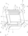
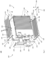
- Fig. 2 shows a perspective view of a first exemplary embodiment of a housing, generally designated by reference number 100, for accommodating an electrical circuit.
- Fig. 2 is an exploded view or shows a pre-assembled state of the housing 100.
- the housing 100 is essentially shown from the side with a front portion.
- the housing 100 includes a rear wall 112, two mutually parallel housing heat sinks 102, and two mutually parallel side walls 110.
- the rear wall 112 can extend in a first transverse direction 204 and a second transverse direction 206.
- the two housing heat sinks 102 can extend in a mounting direction 202 and the first transverse direction 204.
- the first transverse direction 204 can be transverse to the mounting direction 202.
- Each of the two housing heat sinks 102 can be screwed or screwed to a rear side of the housing 116 with the rear wall 112 in the mounting direction 202.
- Each of the housing heat sinks 102 can have two retaining pins 108 extending in the mounting direction on a housing front side 118.
- the two holding pins 108 of each of the two housing heat sinks 102 can be arranged at the edge of the respective housing heat sink 102.
- the two side walls 110 can extend in the mounting direction 202 and the second transverse direction 206.
- the second transverse direction 206 can be transverse to the mounting direction 202 and/or transverse to the first transverse direction 204.
- Each of the two Side walls 110 can have holding pin openings 120 on the housing front 118.
- the holding pin openings 120 (for example per side wall 110) can accommodate one of the two holding pins 108 of each of the two housing heat sinks 102 in a form-fitting manner (for example with respect to the first transverse direction 204 and the second transverse direction 206).
- each of the two side walls 110 on the rear side of the housing 116 can be screwed or screwed to the rear wall 112 in the mounting direction 202.
- first screw connections 138 connect the housing heat sinks 102 to the rear wall 112
- second screw connections 138 connect the side walls 110 to the rear wall 112.
- One or each of the housing heat sinks 102 can carry a circuit board 104 of the electrical circuit on its inner surface.
- one or each of the housing heat sinks can have cooling fins 106 on its outer surface for dissipating heat from the electrical circuit.
- the housing heat sink or the housing heat sinks, each with a printed circuit board pre-mounted thereon, can form a pre-assembled assembly for mounting the housing (for example a corresponding electrical device).
- One or each of the side walls 110 can comprise on the housing front 118 a front web 122 extending in the first transverse direction 204 and the second transverse direction 206, for example an end of a stamped part bent at 90 degrees.
- the front bar 122 can have the retaining pin openings 120.
- the front web 122 allows the side walls 110 to be rigid on the front of the housing without screw connections using a front cap.
- One or each of the side walls can comprise cantilevered tongues on the back of the housing parallel to the first transverse direction 204.
- the tongues can Screw openings (for example, each tongue can have one screw opening) for screwing the respective side wall 110 to the rear wall 112.
- the housing 100 may further include a front cap 126.
- the front cap 126 can be attached or attachable to the side walls 110 and the housing heat sink 102 on the housing front 118 against the mounting direction 202.
- the front cap 126 can include locking elements 128 that extend counter to the mounting direction 202.
- the side walls 110 and/or the housing heat sinks 102 can have locking recesses 130 which are arranged to receive the locking elements for (preferably reversible) locking when the front cap 126 is attached.
- the housing heat sinks 102 may include aluminum, copper and/or steel.
- the side walls 110 may comprise aluminum, copper and/or sheet steel.
- the material of the front cap 126 often has no electrical (and/or low thermal) conductivity. It is preferably made of plastic, for example thermoplastic material. This is also advantageous for the various projections of the actual front cap in the form of locking elements 128 and guide pins, which can be produced together with the actual front flap 126 in an injection molding process with the same material.
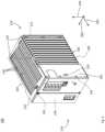
- Fig. 3 shows a perspective view of the housing 100 according to a second exemplary embodiment in a pre-assembled state.
- the second exemplary embodiment can be a further development of the first exemplary embodiment.
- identical reference symbols designate features which in themselves can be the same or interchangeable with those of the first exemplary embodiment.
- the side walls 110 can include ventilation grille panels. That is, one or each of the side walls 110 may include ventilation openings 136, for example for circulating air between the interior and exterior of the housing.
- the ventilation openings 136 can be arranged according to a grid (for example a section of a Bravais grid).
- the grid can be rectangular or (as exemplified in Fig. 3 shown) may be oblique.
- one or each of the side walls 110 may have ventilation openings 136 with a Area proportion of more than half of the convex outer shell of the respective side wall 110.
- the ventilation openings 136 can extend in the mounting direction 202 over the entire length of the respective side wall 110 except for locking recesses 130 for receiving locking elements 128 of the front cap 126. In any case, the ventilation openings 136 can extend over a length that is greater than a section with the Cooling fins 106 of the housing heat sink 102.
- both housing heat sinks 102 each have (for example at least) one holding pin 108 at the top and bottom in the first transverse direction 204.
- the ventilation grille plates 110 are pushed on from the front via these holding pins 108 and in the rear area (i.e. on the Rear housing 116) pulled around the rear wall 112.
- the ventilation grille plates 110 are fastened to the rear wall 112 from behind (i.e. in the mounting direction 202) with screws 138.
- What is particularly special is the stable and robust connection (for example by means of the secured positive fit) between the holding pins 108 and the holding pin openings 120 of the ventilation grille plates 110 in the front area (i.e. on the housing front 118) without a screwing process.
- the front cap 126 may include guide pins 132.
- the side walls 110 and/or the housing heat sinks 102 may include guide bridges 134 which are arranged to receive the guide pins 132 against the mounting direction 202 when the front cap 126 is attached.
- the guide pins 132 can be arranged circumferentially on the edges of the front cap 126, for example on the edges of the front cap 126 extending in the first transverse direction and on the edges of the front cap 126 extending in the second transverse direction.
- the front cap 126 is finally guided into the previous structure from the front (i.e. against the assembly direction 202).
- the front cap 126 has guide retaining pins 132 (in short: guide pins) all around, which slide into the guide bridges 134 of the housing heat sink 102 and ensure the precise positioning of the front cap 126.
- the locking elements 128, which are also arranged all around in the front cap 126, lock in the end stop in the ventilation grille plates 110 and housing heat sink 102 (ie in the locking recesses 130 of the ventilation grille plates 110 and housing heat sink 102).
- the cooling fins 106 can extend parallel to one another and each in the first transverse direction 204.
- the cooling fins 106 may include a portion of the outside (ie, the outer surface) of the housing heat sink 102.
- the side walls 110 can have a recess corresponding to the section on one or each of their longitudinal edges extending in the mounting direction 202.
- the recess allows the cooling fins 106 to be exposed in the first transverse direction.
- the recess can correspond to a taper of the side wall or side walls in the second transverse direction.
- a size of the recess in the second transverse direction 206 can correspond to a size of the cooling fins 106 in the second transverse direction 206.
- Fig. 5 shows a flowchart of a method 500 for producing the housing 100 according to one of the exemplary embodiments, for example a method for mounting the ventilation grille plates 110 and the front cap 126 to the housing heat sink 102 screwed to the rear wall 112.
- the method 500 for manufacturing a housing 100 may include a step of providing 502 the features (e.g., components) of the housing 100 according to one embodiment.
- the electrical circuit board 104 (or boards 104) may be pre-assembled on the interior surface of one or each of the housing heat sinks prior to mounting 504 of the housing 100.
- step 502 two assemblies can be prepared for assembly, each comprising a left and right housing heat sink 102, each with a screwed circuit board 104.
- the method may include a step of assembling 504 the housing 100.
- the mounting direction 202 of all screws 138 used can be identical.
- both housing heat sinks 102 are mounted parallel to each other, with the cooling fins 106 directed outwards, in a U-shape with the rear wall 112 from behind with screws 138.
- a simplified assembly 504 of the housing 100 can advantageously be achieved in this way, since in particular a single screw assembly direction 202 keeps the complexity of the assembly low. In particular, automated and/or reliable assembly can thus be realized.
- the housing 100 with the electrical circuitry may be a power supply.
- the at least one circuit board 104 includes the associated circuit elements (electronic components) of the power supply.
- the power supply can be supplemented by an overcurrent protection device (technically “circuit breaker", CB) and/or by components for an uninterruptible power supply (UPS or technically UPS), which are also arranged in the housing.
- UPS uninterruptible power supply
- Such a module can, for example, be screwed onto the second of the two housing heat sinks 102 (not shown).
- the dimensions of the side walls 110 of the housing 100 in the case of a power supply without a CB module and/or without a UPS module differ from the dimensions of the side walls of the housing 100 in the case of a power supply with a CB and/or with a UPS in their extent in the second transverse direction 206, while the extent of the side wall 110 in the first transverse direction 204 is uniform.
- a correspondingly sized larger rear wall 112 and front cap 126 are therefore also used.
Landscapes
- Engineering & Computer Science (AREA)
- Microelectronics & Electronic Packaging (AREA)
- Physics & Mathematics (AREA)
- Thermal Sciences (AREA)
- Cooling Or The Like Of Electrical Apparatus (AREA)
Applications Claiming Priority (1)
| Application Number | Priority Date | Filing Date | Title |
|---|---|---|---|
| LU502656A LU502656B1 (de) | 2022-08-11 | 2022-08-11 | Gehäuse für eine elektrische Schaltung und zugehöriges Herstellungsverfahren |
Publications (2)
| Publication Number | Publication Date |
|---|---|
| EP4322716A1 true EP4322716A1 (fr) | 2024-02-14 |
| EP4322716B1 EP4322716B1 (fr) | 2026-02-25 |
Family
ID=83898234
Family Applications (1)
| Application Number | Title | Priority Date | Filing Date |
|---|---|---|---|
| EP23190575.3A Active EP4322716B1 (fr) | 2022-08-11 | 2023-08-09 | Boîtier pour circuit électrique et procédé de fabrication associé |
Country Status (2)
| Country | Link |
|---|---|
| EP (1) | EP4322716B1 (fr) |
| LU (1) | LU502656B1 (fr) |
Citations (3)
| Publication number | Priority date | Publication date | Assignee | Title |
|---|---|---|---|---|
| EP0040752B1 (fr) | 1980-05-22 | 1984-09-12 | Siemens Aktiengesellschaft | Connecteurs galvaniquement découplables pour énergie et/ou signaux électriques |
| EP1845763A2 (fr) * | 2006-04-12 | 2007-10-17 | DResearch Digital Media Systems GmbH | Boîtier de réception de circuits imprimés et/ou d'autres composants électroniques et/ou électriques |
| EP2119970A2 (fr) | 2008-05-13 | 2009-11-18 | BSH Bosch und Siemens Hausgeräte GmbH | Système de montage destiné au montage d'un boîtier de hotte aspirante pouvant être fixé sur un mur ainsi que procédé de fixation d'un boîtier correspondant |
-
2022
- 2022-08-11 LU LU502656A patent/LU502656B1/de active IP Right Grant
-
2023
- 2023-08-09 EP EP23190575.3A patent/EP4322716B1/fr active Active
Patent Citations (3)
| Publication number | Priority date | Publication date | Assignee | Title |
|---|---|---|---|---|
| EP0040752B1 (fr) | 1980-05-22 | 1984-09-12 | Siemens Aktiengesellschaft | Connecteurs galvaniquement découplables pour énergie et/ou signaux électriques |
| EP1845763A2 (fr) * | 2006-04-12 | 2007-10-17 | DResearch Digital Media Systems GmbH | Boîtier de réception de circuits imprimés et/ou d'autres composants électroniques et/ou électriques |
| EP2119970A2 (fr) | 2008-05-13 | 2009-11-18 | BSH Bosch und Siemens Hausgeräte GmbH | Système de montage destiné au montage d'un boîtier de hotte aspirante pouvant être fixé sur un mur ainsi que procédé de fixation d'un boîtier correspondant |
Also Published As
| Publication number | Publication date |
|---|---|
| LU502656B1 (de) | 2024-02-12 |
| EP4322716B1 (fr) | 2026-02-25 |
Similar Documents
| Publication | Publication Date | Title |
|---|---|---|
| EP1192845B1 (fr) | Ventilateur a filtre pouvant etre monte dans un evidement de paroi | |
| EP1732375A2 (fr) | Ventilateur d'appareil | |
| DE68908778T2 (de) | Anordnung zur Befestigung von Schutzgittern oder Sichtblenden an Geräten, insbesondere an elektrischen und elektronischen Geräten. | |
| DE112014001321T5 (de) | Elektronikkomponenten-Anordnungsaufbau und elektrischer Anschlusskasten | |
| EP3804482B1 (fr) | Appareil électrique ou électronique comprenant un boîtier avec deux zones protégées entre elles par un blindage électromagnétique | |
| DE102020124822A1 (de) | Elektrisches Wechselrichter-System | |
| LU502656B1 (de) | Gehäuse für eine elektrische Schaltung und zugehöriges Herstellungsverfahren | |
| EP3487271A1 (fr) | Appareil enfichable ainsi que support de module | |
| BE1030623B1 (de) | Vorrichtung und Verfahren für Gehäuse elektrischer Geräte | |
| DE3507255A1 (de) | Gehaeuse fuer elektrische bauteile | |
| DE102022120280A1 (de) | Gehäuse für eine elektrische Schaltung und zugehöriges Herstellungsverfahren | |
| DE102019101859A1 (de) | Kontakt- und Busschienenanordnung, Elektronikgehäuseanordnung mit einer solchen Kontakt- und Busschienenanordnung, und Verfahren zur Entnahme eines Elektronikgehäuses aus einer solchen Elektronikgehäuseanordnung | |
| EP0596349A2 (fr) | Support pour installation électrique | |
| DE60223782T2 (de) | Kombination von Frontplatten | |
| EP4068923A1 (fr) | Dispositif de refroidissement destiné au refroidissement d'un module semi-conducteur et onduleur pourvu de dispositif de refroidissement | |
| DE102022209492B3 (de) | Kühlkörper für ein Halbleiterschaltgerät sowie Halbleiterschaltgerät | |
| DE102022114919A1 (de) | Vorrichtung und Verfahren für Gehäuse elektrischer Geräte | |
| DE102004004598B3 (de) | Kühlanordnunng für ein Computersystem | |
| DE202018007023U1 (de) | Modulares Gehäuse | |
| WO2018069340A1 (fr) | Boîtier destiné à recevoir une carte de circuit imprimé en une ou plusieurs parties | |
| EP1102527B1 (fr) | Boîtier protégé contre les décharges électrostatiques | |
| DE19931908C2 (de) | Elektronische Anlage | |
| DE102024114051A1 (de) | Befestigungsformelement zum Befestigen einer Tragschiene an einer Montagebasis | |
| DE8800296U1 (de) | Steckverbinder für externe Codierung | |
| DE19643612A1 (de) | Kühlkörper für einen IC-Baustein und Montageverfahren dafür |
Legal Events
| Date | Code | Title | Description |
|---|---|---|---|
| PUAI | Public reference made under article 153(3) epc to a published international application that has entered the european phase |
Free format text: ORIGINAL CODE: 0009012 |
|
| STAA | Information on the status of an ep patent application or granted ep patent |
Free format text: STATUS: REQUEST FOR EXAMINATION WAS MADE |
|
| 17P | Request for examination filed |
Effective date: 20230809 |
|
| AK | Designated contracting states |
Kind code of ref document: A1 Designated state(s): AL AT BE BG CH CY CZ DE DK EE ES FI FR GB GR HR HU IE IS IT LI LT LU LV MC ME MK MT NL NO PL PT RO RS SE SI SK SM TR |
|
| GRAP | Despatch of communication of intention to grant a patent |
Free format text: ORIGINAL CODE: EPIDOSNIGR1 |
|
| STAA | Information on the status of an ep patent application or granted ep patent |
Free format text: STATUS: GRANT OF PATENT IS INTENDED |
|
| RIC1 | Information provided on ipc code assigned before grant |
Ipc: H05K 5/00 20060101AFI20250910BHEP Ipc: H05K 5/04 20060101ALI20250910BHEP Ipc: H01F 27/02 20060101ALI20250910BHEP Ipc: H05K 7/20 20060101ALI20250910BHEP Ipc: H05K 5/10 20250101ALI20250910BHEP |
|
| INTG | Intention to grant announced |
Effective date: 20250925 |
|
| GRAS | Grant fee paid |
Free format text: ORIGINAL CODE: EPIDOSNIGR3 |
|
| GRAA | (expected) grant |
Free format text: ORIGINAL CODE: 0009210 |
|
| STAA | Information on the status of an ep patent application or granted ep patent |
Free format text: STATUS: THE PATENT HAS BEEN GRANTED |
|
| AK | Designated contracting states |
Kind code of ref document: B1 Designated state(s): AL AT BE BG CH CY CZ DE DK EE ES FI FR GB GR HR HU IE IS IT LI LT LU LV MC ME MK MT NL NO PL PT RO RS SE SI SK SM TR |
|
| REG | Reference to a national code |
Ref country code: CH Ref legal event code: F10 Free format text: ST27 STATUS EVENT CODE: U-0-0-F10-F00 (AS PROVIDED BY THE NATIONAL OFFICE) Effective date: 20260225 Ref country code: GB Ref legal event code: FG4D Free format text: NOT ENGLISH |
|
| REG | Reference to a national code |
Ref country code: DE Ref legal event code: R096 Ref document number: 502023003141 Country of ref document: DE |
|
| REG | Reference to a national code |
Ref country code: IE Ref legal event code: FG4D Free format text: LANGUAGE OF EP DOCUMENT: GERMAN |
|
| P01 | Opt-out of the competence of the unified patent court (upc) registered |
Free format text: CASE NUMBER: UPC_APP_0006579_4322716/2026 Effective date: 20260224 |