EP4322875B1 - Dispositif d'ostéosynthèse pour le traitement de la colonne vertébrale et système de fixation associé - Google Patents
Dispositif d'ostéosynthèse pour le traitement de la colonne vertébrale et système de fixation associé Download PDFInfo
- Publication number
- EP4322875B1 EP4322875B1 EP22723556.1A EP22723556A EP4322875B1 EP 4322875 B1 EP4322875 B1 EP 4322875B1 EP 22723556 A EP22723556 A EP 22723556A EP 4322875 B1 EP4322875 B1 EP 4322875B1
- Authority
- EP
- European Patent Office
- Prior art keywords
- opening
- bone anchor
- receiving area
- attachment system
- fixing
- Prior art date
- Legal status (The legal status is an assumption and is not a legal conclusion. Google has not performed a legal analysis and makes no representation as to the accuracy of the status listed.)
- Active
Links
Images


Classifications
-
- A—HUMAN NECESSITIES
- A61—MEDICAL OR VETERINARY SCIENCE; HYGIENE
- A61B—DIAGNOSIS; SURGERY; IDENTIFICATION
- A61B17/00—Surgical instruments, devices or methods
- A61B17/56—Surgical instruments or methods for treatment of bones or joints; Devices specially adapted therefor
- A61B17/58—Surgical instruments or methods for treatment of bones or joints; Devices specially adapted therefor for osteosynthesis, e.g. bone plates, screws or setting implements
- A61B17/68—Internal fixation devices, including fasteners and spinal fixators, even if a part thereof projects from the skin
- A61B17/70—Spinal positioners or stabilisers, e.g. stabilisers comprising fluid filler in an implant
- A61B17/7001—Screws or hooks combined with longitudinal elements which do not contact vertebrae
- A61B17/7032—Screws or hooks with U-shaped head or back through which longitudinal rods pass
-
- A—HUMAN NECESSITIES
- A61—MEDICAL OR VETERINARY SCIENCE; HYGIENE
- A61B—DIAGNOSIS; SURGERY; IDENTIFICATION
- A61B17/00—Surgical instruments, devices or methods
- A61B17/56—Surgical instruments or methods for treatment of bones or joints; Devices specially adapted therefor
- A61B17/58—Surgical instruments or methods for treatment of bones or joints; Devices specially adapted therefor for osteosynthesis, e.g. bone plates, screws or setting implements
- A61B17/68—Internal fixation devices, including fasteners and spinal fixators, even if a part thereof projects from the skin
- A61B17/70—Spinal positioners or stabilisers, e.g. stabilisers comprising fluid filler in an implant
- A61B17/7001—Screws or hooks combined with longitudinal elements which do not contact vertebrae
- A61B17/7035—Screws or hooks, wherein a rod-clamping part and a bone-anchoring part can pivot relative to each other
- A61B17/7037—Screws or hooks, wherein a rod-clamping part and a bone-anchoring part can pivot relative to each other wherein pivoting is blocked when the rod is clamped
-
- A—HUMAN NECESSITIES
- A61—MEDICAL OR VETERINARY SCIENCE; HYGIENE
- A61B—DIAGNOSIS; SURGERY; IDENTIFICATION
- A61B17/00—Surgical instruments, devices or methods
- A61B17/56—Surgical instruments or methods for treatment of bones or joints; Devices specially adapted therefor
- A61B17/58—Surgical instruments or methods for treatment of bones or joints; Devices specially adapted therefor for osteosynthesis, e.g. bone plates, screws or setting implements
- A61B17/68—Internal fixation devices, including fasteners and spinal fixators, even if a part thereof projects from the skin
- A61B17/70—Spinal positioners or stabilisers, e.g. stabilisers comprising fluid filler in an implant
- A61B17/7074—Tools specially adapted for spinal fixation operations other than for bone removal or filler handling
- A61B17/7076—Tools specially adapted for spinal fixation operations other than for bone removal or filler handling for driving, positioning or assembling spinal clamps or bone anchors specially adapted for spinal fixation
-
- A—HUMAN NECESSITIES
- A61—MEDICAL OR VETERINARY SCIENCE; HYGIENE
- A61B—DIAGNOSIS; SURGERY; IDENTIFICATION
- A61B17/00—Surgical instruments, devices or methods
- A61B17/56—Surgical instruments or methods for treatment of bones or joints; Devices specially adapted therefor
- A61B17/58—Surgical instruments or methods for treatment of bones or joints; Devices specially adapted therefor for osteosynthesis, e.g. bone plates, screws or setting implements
- A61B17/68—Internal fixation devices, including fasteners and spinal fixators, even if a part thereof projects from the skin
- A61B17/84—Fasteners therefor or fasteners being internal fixation devices
- A61B17/86—Pins or screws or threaded wires; nuts therefor
- A61B17/8625—Shanks, i.e. parts contacting bone tissue
- A61B17/863—Shanks, i.e. parts contacting bone tissue with thread interrupted or changing its form along shank, other than constant taper
-
- A—HUMAN NECESSITIES
- A61—MEDICAL OR VETERINARY SCIENCE; HYGIENE
- A61B—DIAGNOSIS; SURGERY; IDENTIFICATION
- A61B17/00—Surgical instruments, devices or methods
- A61B17/56—Surgical instruments or methods for treatment of bones or joints; Devices specially adapted therefor
- A61B17/58—Surgical instruments or methods for treatment of bones or joints; Devices specially adapted therefor for osteosynthesis, e.g. bone plates, screws or setting implements
- A61B17/68—Internal fixation devices, including fasteners and spinal fixators, even if a part thereof projects from the skin
- A61B17/84—Fasteners therefor or fasteners being internal fixation devices
- A61B17/86—Pins or screws or threaded wires; nuts therefor
- A61B17/8625—Shanks, i.e. parts contacting bone tissue
- A61B17/8635—Tips of screws
-
- A—HUMAN NECESSITIES
- A61—MEDICAL OR VETERINARY SCIENCE; HYGIENE
- A61B—DIAGNOSIS; SURGERY; IDENTIFICATION
- A61B17/00—Surgical instruments, devices or methods
- A61B17/56—Surgical instruments or methods for treatment of bones or joints; Devices specially adapted therefor
- A61B17/58—Surgical instruments or methods for treatment of bones or joints; Devices specially adapted therefor for osteosynthesis, e.g. bone plates, screws or setting implements
- A61B17/68—Internal fixation devices, including fasteners and spinal fixators, even if a part thereof projects from the skin
- A61B17/84—Fasteners therefor or fasteners being internal fixation devices
- A61B17/86—Pins or screws or threaded wires; nuts therefor
- A61B17/864—Pins or screws or threaded wires; nuts therefor hollow, e.g. with socket or cannulated
-
- A—HUMAN NECESSITIES
- A61—MEDICAL OR VETERINARY SCIENCE; HYGIENE
- A61B—DIAGNOSIS; SURGERY; IDENTIFICATION
- A61B17/00—Surgical instruments, devices or methods
- A61B2017/00477—Coupling
Definitions
- the invention relates to a fastening system for spinal treatment and a fastening system therefor.
- osteosynthesis devices for treating the spine, such as pedicle screws, are known in the prior art. Such osteosynthesis devices are used to correct spinal misalignments or stabilize fractures.
- the osteosynthesis devices are inserted and secured into the vertebrae and then connected to one another via longitudinal rods, or so-called connecting rods, in order to fix the vertebrae in a desired position.
- the longitudinal rods are mounted and secured to the osteosynthesis devices in a non-slip manner using locking elements, such as grub screws or other closure elements.
- Pedicle screws are preferably used as osteosynthesis devices. These have a bone anchor that is pivotally mounted in at least one plane with a fork head and is angularly stable when the grub screw is fixed.
- Bone screws with a spherical head are preferably used as bone anchors.
- Osteosynthesis devices with a bone anchor and fork head are usually mounted in such a way that the bone anchor is guided from the proximal end into the fork head through the distal opening of the fork head. This only works if the outer diameter of the bone anchor shaft is smaller than the ball head diameter of the bone anchor and the outer diameter of the bone anchor shaft is smaller than the diameter of the distal opening of the fork head. Installation is problematic if the outer diameter of the bone anchor shaft is larger than the opening diameter of the fork head and/or the ball head diameter of the bone anchor.
- the state of the art is a pedicle screw ( DE102011053295A1 ) is known, which can be temporarily locked and thus allows an expanded range of applications in the treatment of spinal instabilities.
- This makes it possible to perform polyaxial Movable pedicle screws can be inserted into the vertebral bone in any orientation, and the user can then temporarily clamp the angle between the fork head and the bone anchor.
- With temporarily locked polyaxiality it is possible for corrective forces to be introduced onto the bone anchor via the fork head, which directly affects the alignment and position of the vertebral bones. Without this temporary clamping, such corrective maneuvers are difficult or impossible to perform.
- a pedicle screw anchor is known in which the temporary compression force is permanently maintained by means of a detachable pin element.
- this design requires a lever-like actuation of the pressure piece to create the temporary clamping. This results in increased combined compression and bending stress on the pressure piece, which leads to a mechanical limitation of the maximum temporary clamping effect.
- the material thickness of the pressure piece must be dimensioned such that these loads do not have a destructive effect. This means that such a pedicle screw is greater in height than a regular pedicle screw. It is therefore desirable that the temporary clamping effect is not initiated via the pressure piece itself, but acts directly on the bone anchor head area. This mechanically decouples the pressure piece during temporary clamping and the osteosynthesis device can provide reserves with regard to the maximum clamping effect.
- none of these temporarily clampable pedicle screw concepts is capable of accommodating screw shafts coming distally. They can only be used with bone anchors in which the outer diameter of the bone anchor shaft is smaller than the diameter of the distal opening of the fork head.
- the object of the present invention is therefore to enable osteosynthesis devices to be easy, flexible and safe to handle, in particular to be easy, flexible and safe to position and fix, and to have a small installation space.
- pre-fixing or pre-fixed is understood to mean the fixing of the bone anchor in its orientation or position, which ensures that the position or alignment of the bone anchor can be temporarily secured during the surgical implantation of a fastening system or osteosynthesis device, for example in order to connect the osteosynthesis device to other components, such as other osteosynthesis devices, or to precisely insert and/or position them.
- final fixation or finally fixed is understood to mean the fixing of the bone anchor, which ensures that the bone anchor, including any fastening system or osteosynthesis device fixed to it or with it, remains stable in the patient, particularly even with respect to movement-induced loads.
- proximal refers to proximity to the surgeon in the final alignment of the fixation system or osteosynthesis device.
- distal refers to a distance from the surgeon in the final alignment of the fixation system or osteosynthesis device, or, viewed from the proximal end, the opposite end of the fixation system or osteosynthesis device.
- a fastening system for an osteosynthesis device, in particular for spinal treatment, comprises a main body with a first receiving area designed to receive a connecting element, a second receiving area designed to receive a bone anchor, a third receiving area having a linear transverse opening, wherein the transverse opening has a first opening at its first end and a second opening at its second end, and an axial opening for receiving and guiding an adjusting element.
- the fastening system comprises a fixing element having a first fixing pin and a load-bearing area, wherein the first fixing pin the first opening can be inserted into the transverse opening and the fixing element is longer than the transverse opening, and wherein the first fixing pin has a contact surface at its end remote from the load-bearing area, and an adjusting element having a load introduction area, wherein the adjusting element can be positioned and guided by means of the axial opening in such a way that the fixing element can be guided along the transverse opening in the direction of the second receiving area by means of the pressure exerted on the load introduction area by the load introduction area.
- the transverse opening of the pressure piece can, for example, be designed as a cutout.
- the load introduction area is also referred to as the contact area.
- the load absorption area is also referred to as the contact area.
- the contact surface is also referred to as the contact area.
- the second receiving area can be designed as a ball head receiving area.
- the second receiving area is preferably configured such that the proximal end of the bone anchor can be received therein. This proximal end of the bone anchor is also referred to below as the head area of the bone anchor.
- the connecting element serves to connect several osteosynthesis devices and is in particular a connecting rod, particularly preferably a round rod.
- the bone anchor can be designed, for example, as a bone screw or a bone nail.
- the second receiving area is further configured for loose fixation of the bone anchor along its central axis.
- the central axis corresponds to the longitudinal axis of the bone anchor. This prevents unintentional detachment of the bone anchor from the fastening system, for example, the bone anchor falling out of the fastening system, thereby improving handling.
- the transverse opening has a constant cross-section along its guide line. This enables secure guidance of the fixing element in the transverse opening.
- the cross-section of the part of the fixing element that is guided in the transverse opening and the cross-section of the transverse opening are preferably each designed such that, using the two cross-sections, the fixing element can only be inserted into the transverse opening in such a way that the fixing element is in the preferred orientation. This enables time-saving and safe handling.
- the cross-section of the part of the fixing element that is guided in the transverse opening and the cross-section of the transverse opening are complementary to each other. This enables secure guidance of the fixing element with minimal play.
- the first opening is positioned internally.
- the main body is designed such that the fixation element can be inserted into the transverse opening via the second receiving area.
- the first opening is positioned and designed such that the second receiving area is on one side and the third receiving area is on the other side. In this way, it is possible to achieve that the design of the axial opening does not require the fixation element to be insertable into the transverse opening from the outside. In this way, a reduced installation space can be provided, whereby the fastening system can be used on the patient with minimal surgical effort.
- the first opening can also be provided externally. This allows the fixation element to be inserted into the transverse opening even if a bone anchor is already accommodated in the second receiving area.
- the transverse opening is designed and positioned such that, depending on the geometry of the proximal end of the bone anchor, the fixation element can be guided onto the proximal end of the fixation element in a load-optimized manner, for example by preventing the fixation element from hitting an edge of the distal end of the bone anchor.
- the transverse opening is designed and positioned such that, depending on the geometry of the proximal end of the bone anchor, the fixing element can be guided onto the proximal end of the bone anchor such that the The bone anchor is not deflected from this desired orientation, regardless of its orientation in the second receiving area.
- This can be achieved, for example, by guiding the fixation element centered on the distal end of the bone anchor. This increases the flexibility of the fixation system and improves its handling.
- the first fixation pin can at least partially protrude from the transverse opening and be pressed onto the bone anchor received in the second receiving area. This allows the bone anchor to be fixed in the second receiving area.
- the fixing element can be made longer than the transverse opening by making the fixing pin longer than the transverse opening.
- the transverse opening can also be designed such that the load-bearing area is at least partially inserted into it, so that the fixing pin does not necessarily have to be longer than the transverse opening. This allows for a particularly space-saving design.
- the third receiving area is designed such that the transverse opening is provided with an offset to the central axis of the bone anchor received in the second receiving area in the neutral position, wherein the offset is at least 20°, preferably 30° and particularly preferably 40° and a maximum of 80°, preferably 70° and particularly preferably 60°.
- the offset refers to the fact that the fixation element is not pressed onto the bone anchor from proximal to distal, i.e. along the central axis of the bone anchor received in the second receiving area in the neutral position, but is offset from this orientation or axis.
- the offset then occurs by rotating the longitudinal axis of the transverse opening about a rotation point that is positioned essentially centrally in the distal end of the bone screw.
- the neutral position of the bone anchor corresponds to the position of the bone anchor and the main body relative to each other, in which the central axis of the bone anchor runs essentially along the direction of the main body, which starts proximally at the first receiving area and goes towards the second receiving area, i.e. in a distal direction.
- the distal end of the bone anchor is spherically shaped, for example, as a spherical head, and the second receiving area is complementarily spherically shaped. This ensures that even at small offset angles, the distal end of the bone anchor is pressed at least partially perpendicularly onto at least a portion of the surface of the second receiving area.
- the load introduction area and the load-bearing area are designed to complement each other. This ensures that the load to be transferred from the actuating element to the fixing element is transmitted over the largest possible contact area, thereby minimizing the pressure exerted on the contact area. This enables secure and robust guidance of the fixing element.
- the actuator has a thread, for example, if it is designed as a load screw, and the load introduction area is located at the distal end of the actuator, the load-bearing area can be concave. This allows the load to be transferred safely when the actuator rotates.
- the contact surfaces of the load introduction area and the load-bearing area are oriented substantially perpendicular to the longitudinal axis of the transverse opening. This ensures that the load is applied to the fixation element along the transverse opening, minimizing the risk of tilting or wedging of the fixation element. This enables safe handling of the fixation system or osteosynthesis device.
- the fastening system further comprises a pressure piece, wherein the pressure piece has a first receiving area equivalent to the first receiving area of the fastening system, a second receiving area equivalent to the second receiving area of the fastening system and having a plurality of spring elements, and a third receiving area equivalent to the third receiving area of the main body and having a linear transverse opening, and wherein the pressure piece can be inserted into the main body via the first receiving area of the main body.
- the connecting element in the inserted state of the pressure piece, can be received in the fastening system via the two first receiving areas, i.e., via the first receiving area of the main body and the first receiving area of the pressure piece, the bone anchor can be inserted via the two second receiving areas, i.e., the second receiving area of the main body and the second receiving area of the pressure piece, along whose central axis it can be loosely fixed, and the fixing element can be inserted into the transverse openings via the first openings of the two third receiving areas, i.e. via the first opening of the main body and via the first opening of the pressure piece.
- the pressure piece then serves to enable secure final fixation of the bone anchor and then ensures stabilization of the damaged body area.
- This final fixation is achieved by pressing the connecting element onto or into the first receiving area of the pressure piece in such a way that the second receiving area of the pressure piece is deformed in such a way that the spring elements are moved towards one another. If a bone anchor or the proximal end of a bone anchor is now located in the second receiving area of the pressure piece, the spring elements are pressed onto it, resulting in a frictional or force-lock connection between the second receiving area of the pressure piece and the bone anchor or its proximal end.
- the first receiving area of the pressure piece is also referred to as the rod bearing.
- the second receiving area of the pressure piece is also referred to below as the bone anchor head area.
- the spring element is also referred to below as the arm or spring-elastic arm.
- the third receiving area of the pressure piece is designed such that no force-locking connection can result between the fixation element and the pressure piece, particularly preferably even when the fixation element is pressed onto the bone anchor.
- This enables secure pre-fixation of the bone anchor, while simultaneously preventing jamming or tilting of the pressure piece, thus ultimately also enabling secure final fixation of the bone anchor.
- large-area recesses can be provided in the transverse opening of the pressure piece, which are preferably designed to complement the first fixation pin or, if appropriate, to complement additional fixation pins.
- the pressure piece is further configured to enable a first insertion position in which the bone anchor can be inserted into the second receiving area of the main body, and a second insertion position in which the bone anchor can no longer be removed from the main body.
- the pressure piece can be adjusted from proximal to distal so that it is inserted into the first receiving area of the main body, without being displaced as far as the distal end of the first receiving area of the main body. From there, the second insertion position can then be reached by inserting or pushing the pressure piece further distally into the first receiving area of the main body.
- the spring elements of the pressure piece can be briefly deflected radially before subsequently pivoting back into their neutral position.
- the distal ends of the spring elements block the distal end of the second receiving area of the main body, preventing the bone anchor from being removed distally from the main body. This prevents the bone anchor from being lost, thus enabling safe handling of the fixation system or osteosynthesis device.
- the second receiving area can be designed to taper distally.
- the axial opening has an internal thread and the adjusting element has an external thread, and the internal thread of the axial opening is complementary to the external thread of the adjusting element.
- the external thread of the adjusting element is also referred to below as the thread.
- the first receiving area of the main body further has an internal thread proximally. This allows the connecting element to be pressed into the first receiving area(s) by means of a screw, for example, a grub screw.
- the thread diameter of the axial opening and the thread diameter of the adjusting element are smaller than the thread diameter of the first receiving area of the main body. In this way, a small space requirement of the fixation system, thereby minimizing tissue damage occurring during surgical implantation in the patient.
- the internal thread of the axial opening and the external thread of the adjusting element have a thread pitch that is smaller than the thread pitch of the internal thread of the first receiving area of the main body.
- the tightening torque required to load the adjusting element can be reduced, thereby reducing the torsional load on the adjusting element and simultaneously enabling secure fixation of the bone anchor by the fixation element.
- the adjusting element is designed with smaller dimensions, for example, with a smaller circumference, than the grub screw to be accommodated in the first receiving area of the main body, since the adjusting element then has lower torsional strength.
- the internal thread of the axial opening and the external thread of the adjusting element have a pitch of a maximum of 1.00 mm per revolution, preferably less than 0.85 mm per revolution, particularly preferably less than 0.70 mm per revolution, and a minimum of 0.1 mm per revolution, preferably 0.2 mm per revolution, particularly preferably 0.3 mm per revolution.
- This can achieve, on the one hand, a reduction in the torsional load on the adjusting element, while, at the same time, the adjusting element generates a significantly higher axial preload in the axial opening, thereby improving the handling of the fastening system.
- the internal thread of the axial opening runs substantially parallel to the central axis of the bone anchor, which is received in the second receiving area in the neutral position.
- This enables a space-saving design of the fastening element, thereby reducing tissue damage that occurs during surgical implantation of the osteosynthesis device.
- it makes it possible to actuate the actuating element and the grub screw received in the first receiving area of the main body in a similar manner and in close proximity to one another, thereby improving handling.
- the axial opening prefferably aligned parallel to the main axis of the transverse opening of the main body. In this way, the frictional connection between the adjusting element and the fixing element, and ultimately between the fixing element and Bone anchors can be maximized, which in turn increases the reliability and stability of the fixation system.
- transverse opening of the main body is oriented substantially perpendicular to the central axis of the bone anchor, which is received in the neutral position in the second receiving area of the main body. This allows for maximum clamping action with respect to the bone anchor.
- the axial opening preferably has at least one pressing opening, wherein the pressing opening is positioned at the distal end of the internal thread, and wherein the pressing opening is designed such that it enables the external thread of the adjusting element to be compressed.
- Pressing is understood to mean a local deformation of the external thread of the adjusting element which is so intensive that when the deformed external thread section engages an internal thread that is fundamentally complementary to this external thread, the deformed or compressed external thread section jams in the internal thread.
- the axial opening has several compression openings, for example two, which are particularly preferably positioned opposite one another. This enables uniform compression without potentially damaging the surrounding structures.
- the internal thread formed in the axial opening ends distally before the compression opening(s). After the external thread of the adjusting element has been compressed, it is possible to screw it further distally into the axial opening, while at the same time preventing it from being unscrewed proximally.
- the fixation element preferably also has a second fixation pin.
- the load points are created via the contact surfaces between the distal ends of the first and second fixation pin and the bone anchor. Based on the respective contact surface, the area located on the opposite side of the bone anchor, and the direction of load introduction, a load direction or load axis is created. If the fixed bone anchor is then loaded, for example during surgical implantation, sometimes different clamping resistances result. If this load occurs along the load axis, a high clamping resistance results. However, if the load occurs away from the load axis, for example in the form of a torsional load around the load axis, a low clamping resistance results.
- a single fixation pin in such a way that it has a contact surface that, when engaged with the bone anchor, results in multiple loading axes. This can be achieved, for example, by providing two spaced-apart elevations on the contact surface.
- the fixation element is designed such that, when clamped, a three-point support or three-point loading is achieved. This enables secure clamping of the bone anchor in a simple manner, regardless of the loading situation.
- the contact surface of the first fixation pin, or optionally of the first and/or second fixation pin is complementary to a corresponding contact surface of the bone anchor. This enables a secure and material-friendly load transfer from the fixation pins to the bone anchor.
- the contact surface of the first fixation pin or, where applicable, the first and/or second fixation pin is configured such that the contact area between the first fixation pin or, where applicable, the first and/or second fixation pin and the bone anchor is maximized. This also maximizes the corresponding friction surface, which in turn maximizes the frictional connection.
- the fixation system is designed for a bone anchor with a spherical head.
- a spherically concave contact surface of the fixation pin adapted to this spherical head allows the bone anchor to be securely pre-fixed regardless of its twisting position.
- a twisting position is defined as any possible position of the bone anchor geometrically determined based on the main body and the proximal end of the bone anchor.
- the approximate diameter of the spherically concave curved contact surface of the first fixation pin or, where applicable, of the first and/or second fixation pin is smaller than the diameter of the proximal end of the bone anchor, which is designed as a spherical head. This makes it possible for the resulting contact surface to be subjected to additional shear stress when the first fixation pin or, where applicable, the first and/or second fixation pin is pressed onto the proximal end of the bone anchor, for example in the form of a crimp.
- load it is possible for load to be transmitted over the largest possible area despite the increasing bending of the distal end of the first fixation pin or, where applicable, the distal ends of the first and/or second fixation pin with increasing press-on pressure. Furthermore, it is possible for the main load-bearing regions of the resulting contact surfaces to be displaced further radially outwards with respect to the fixation pin, thereby generating increased clamping resistance, particularly with respect to rotational loading about the corresponding load axis.
- the approximate diameter is the diameter of the sphere or the circle that results if the spherical-concave curvature were extended until one came back to the starting point.
- the approximate diameter of the spherically concave curved contact surface of the first fixing pin or optionally of the first and/or second fixing pin is at most 1.00 mm, preferably 0.50 mm, particularly preferably 0.20 mm and at least 0.01 mm, preferably 0.02 mm, particularly preferably 0.05 mm larger than the diameter of the proximal end of the bone anchor designed as a spherical head.
- a spring element is arranged in the linear transverse opening of the pressure piece, and this spring element is in particular positioned centrally in the linear transverse opening.
- the spring element arranged in the linear transverse opening is widened in the distal region. This ensures that, when the pressure piece is inserted and the fixation element is inserted into its transverse opening, the pressure piece is prevented from accidentally protruding proximally from the main body.
- the fixation element also functions as a loss prevention device for the pressure piece. Furthermore, this maximizes the potential contact area between the spring elements and the proximal end of the bone anchor, thereby maximizing the clamping effect of the final fixation.
- the contact surface of the first fixing pin, or optionally of the first and/or second fixing pin has a locally increased surface roughness. This can increase the friction effect and thus the pre-fixing effect.
- the surface roughness can be created, for example, by roughening or by providing notches and/or teeth.
- the proximal end of the bone anchor has a locally increased surface roughness. This can increase the friction effect and thus the effectiveness of the pre-fixation and the final fixation.
- the contact surface of the pressure piece has a locally increased surface roughness. This can increase the friction effect and thus the effectiveness of the final fixation.
- the first receiving area is designed as a U-shaped fork head with a first fork leg and a second fork leg. This enables a weight-optimized and space-optimized design, which, for example, improves the handling of the fixation system or osteosynthesis device, particularly during surgical implantation in a patient.
- the first receiving area of the main body has a thread.
- a screw for example, a space-saving grub screw, in particular indirectly via the pressure piece onto the bone anchor.
- both fork legs can have a corresponding threaded section.
- the first fork leg then has a threaded section complementary to the threaded section of the second fork leg, with both threaded sections together forming the thread of the first receiving area of the main body or the fork head.
- the fork legs and thus also the threaded sections formed therein are preferably arranged opposite one another. This enables secure screwing of the connecting element and further reduces weight and installation space.
- the third receiving area and the axial opening are arranged on the first fork leg. This allows the required installation space to be reduced, thereby improving handling.
- the proximal end of the third receiving area of the main body follows the distal end of the axial opening from proximal to distal. This allows the required installation space to be reduced. Furthermore, it makes it possible to insert the fixing element from radially outside to radially inside into the transverse opening of the main body and, if necessary, into the transverse opening of the pressure piece, thereby improving handling.
- the axial opening is configured and positioned, and/or the adjusting element is configured, such that the adjusting element can be positioned such that its distal end can protrude distally from the axial opening in such a way that the radially outer end of the transverse opening of the main body is concealed radially outward.
- An osteosynthesis device in particular for spinal treatment, has a bone anchor and a fastening system according to the invention.
- An alternative osteosynthesis device in particular a polyaxial pedicle screw, consists of a bone anchor having a head, a fork head which is U-shaped in a side view, a pressure piece located therein, an internal fixing element guided in a transverse opening, a detachably connected actuating element for actuating the fixing element, wherein the fixing element is suitable for temporarily clamping the bone anchor head area in all degrees of freedom without the need for a pressure piece or, if present, is not loaded.
- a connecting rod after implantation of the osteosynthesis device into the bone, a connecting rod must be inserted and the osteosynthesis device must be finally fixed in all degrees of freedom using a locking element. This is achieved by screwing the locking element tight.
- an axial compression force is transferred from the locking element to the connecting rod, which presses on the rod support points of the pressure piece and creates a minimal relative movement of the pressure piece further distally, so that the bone anchor is clamped in the ball seat with a stable angle.
- two or more osteosynthesis devices are connected to one another using a connecting rod.
- the fork head is designed so that a connecting rod can be inserted and secured to the fork head with a locking element. As already mentioned, this creates a stable angle clamping between the bone anchor head area and the fork head.
- the stable angle clamping with the aid of the locking element and the stable angle clamping with the aid of the fixation element function independently of each other in the inventive structure. They can be activated separately or in combination.
- the fork head has a through-opening and forms two fork legs in the proximal direction with an internal thread for a locking element.
- a ball head receiving area is provided in the through-opening, in which a bone anchor is pivotably mounted.
- Bone screws which can be screwed into a bone, are preferably used as bone anchors. However, hooks, blade-like anchors, clamps, nails, and other types of bone anchors are also applicable.
- the essential features of the bone anchor are a ball-like head, a neck area, and an area that can be anchored or fixed in or to the bone. This patent application will primarily address the fork head, and Bone anchors are understood to mean all conceivable elements that can be connected to a bone.
- a key feature is that the center of the internal thread and the center of the ball head receiving area define the position and orientation of the central axis.
- An axial opening for the adjusting element is provided to the side and at a distance greater than the diameter of the locking element.
- the axial opening is arranged mainly parallel to the central axis. This allows the adjusting element to be driven from the same direction as the locking element using instruments.
- the adjusting element is guided in the axial opening so that its length can be adjusted.
- the term axial opening refers not only to openings that are completely enclosed by material, but also to partial openings or partial cutouts such as C-shaped cutouts perpendicular to the central axis (103).
- An additional opening a transverse opening, is provided perpendicular to the axial opening and the central axis.
- the transverse opening creates a connection between the axial opening and the through-opening of the fork head.
- the fixation element is movably guided in this transverse opening along the transverse opening axis. By applying a compression force along the transverse opening axis, the fixation element clamps the head region of the bone anchor in the fork head at a stable angle.
- the temporary clamping or compression force is preferably generated by adjusting an adjusting element that is guided in the axial opening.
- the compression force is transferred or redirected to the fixation element, resulting in a compression force along the transverse opening axis, which leads to the temporary clamping of the bone anchor head area in the fork head.
- the temporary clamping or the introduction of a compression force could be achieved via the fixing element itself. This would require, for example, that the fixing element and the transverse opening engage with each other via a threaded section, thus enabling length adjustment.
- a characteristic feature of the osteosynthesis device is that the transverse opening axis of the fixation element is approximately aligned with the virtual center of the The ball head receiving area is directed and intersects the central axis. This allows the compression force to be directed to the pivot center of the bone anchor in the fork head, achieving optimal clamping.
- the fork head provides a lateral bulge or material thickening to accommodate the axial opening, transverse opening and the elements required for actuation (adjusting and fixing element).
- the fork head has a pressure piece, which has a distally directed contact area with the bone anchor head region and a proximally directed rod bearing.
- a lateral opening or a partial cutout is provided in the area of the bone anchor head region, in which the fixation element is arranged for free movement. This allows activation of the fixation element without loading the pressure piece.
- the fork head can be mounted with bone anchors from the distal end.
- This advantageous arrangement of the components allows the bone anchors to be mounted relatively easily with the fork head by placing or pressing them on.
- the bone anchor can also be removed again using an aid such as a release instrument.
- the advantage is that, on the one hand, larger bone anchors—that is, bone anchors with a larger outer diameter than the distal inner diameter of the fork head—can be mounted.
- the bone anchor portfolio can be minimized, as the user can combine the fork head and bone anchor during surgery instead of relying on a prefabricated, oversized portfolio.
- Such a portfolio must be kept in stock by the user, thus tying up significantly more capital than would be required for the modular version according to the invention.
- the pressure piece has open slots in the distal direction and thus at least three spring-elastic arms are formed on the head receiving area.
- the spring-elastic arms can deflect radially outwards and thus enclose the bone anchor head area. This allows a bone anchor coming from the distal direction to be clipped into the pressure piece.
- the pressure piece forms a cone at least in sections at the distal end of the outer side. At least one inner cone section is defined in the fork head at the level of the ball receiving area, which congruent with the cone of the pressure piece and, when the locking element is actuated, leads to the angularly stable clamping of the bone anchor head area with the fork head.
- the pressure piece provides a through-opening for the fixation element so that the pressure piece is not loaded when the temporary clamping is activated.
- a circumferential groove with a hook-like profile is provided on the proximal fork head area, providing a rear grip for an instrument.
- Other groove profile designs or other holding features, such as openings that provide a rear grip for an instrument, are conceivable.
- detachable sections with a threaded area that allow for repositioning the connecting rod. It is also conceivable that a sleeve-like access formed by two longer legs is provided, as used for minimally invasive access.
- the detachable leg extensions can optionally be connected to each other at the proximal end. Detachable connections, for example, refer to predetermined breaking points suitable for removing the extensions after the connecting rod has been finally fixed.
- All metallic alloys known and accepted as orthopedic implant materials are suitable. These include, for example, titanium, cobalt-chromium, and stainless steel alloys. If conventional manufacturing of the fork head and locking ring is not possible or only possible with the greatest technological effort, additive manufacturing is the method of choice. Additive manufacturing of metallic alloys, also known as 3D printing, uses laser or electron beam melting processes.
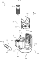
- an osteosynthesis device 1 for treating the spine, wherein more than one osteosynthesis device 1 is used to connect one or more vertebrae to one another using connecting rods 50 and thus stabilize the spine.
- spatial coordinate references are defined, such as the proximal direction 101, the distal direction 102, which extend along a central axis 103.
- Radial extension 104 and circumferential extension 105 are defined outwardly from the central axis 103 by a constant radius and a variable circumferential angle ( Fig. 1 ).
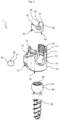
- Fig. 1a, 1b and Fig. 2 show the osteosynthesis device 1 for treating the spine, consisting of a fork head 10 which is U-shaped in a side view and has a through-opening 18 and the fork head 10 has two fork legs 11, 12 with an internal thread 16 in the proximal direction 101, and a connecting rod 50 can be received therein, and in the fork head 10 in the distal direction 102 in the through-opening 18 a ball head receiving area 19 is provided and a bone anchor 90 is pivotally mounted therein, wherein the center of the internal thread 16 and the center of the ball head receiving area 19 define a central axis 103 and at least one leg 11, 12 provides an axial opening 14 arranged parallel to the central axis 103 for an adjusting element 40.
- a transverse opening 13 is provided, which communicates with the axial opening 14 and with the through-opening of the fork head 18.
- a fixing element 30 is arranged along movably guided along an axis 130.
- the fixation element 30 clamps the head region 91 of the bone anchor 90 in a stable angle in the fork head 10.
- the head region of the bone anchor 91 in the fork head 10 becomes movable again.
- the bone anchor 90 preferably has a head region 91 with a tool attachment point 92 located therein and has a bone thread 93 in the distal direction 102.
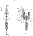
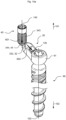
- the osteosynthesis device 1 preferably has a pin-shaped adjusting element 40, which has a tool attachment point 42 in the proximal direction 101 ( Fig. 3 ).
- the adjusting element 40 is designed to be detachable and can also be removed if necessary ( Fig. 1b ). With the adjusting element 40 removed and the fixing element 30 not temporarily clamped, this osteosynthesis device 1 behaves like a polyaxial pedicle screw.
- Fig. 1a and Fig. 2 also illustrate that the fork head 10 of the osteosynthesis device 1 has a pressure piece 20 and that the pressure piece has a through-opening 28, a distally directed contact area with the bone anchor head area 29, a proximally directed rod bearing 25, which is delimited by two legs 21, 22 and has a lateral opening or partial cutout 23 in the area of the bone anchor head area 29, in which the fixation element 30 is arranged to be freely movable. If a connecting rod 50 is inserted into the U-shaped fork opening 15, the connecting rod 50 is in direct contact with the rod bearing of the pressure piece 25.
- Fig. 2 shows the preferred construction of the fixing element 30.
- the fixing element 20 is preferably designed as a round rod and is movably mounted in a concentric transverse opening 13.
- Alternative designs of the fixing element 20, not shown here, are also conceivable, such as, for example, that the fixing element is shown in a sectional view transverse to the transverse opening axis 130 as a triangle, square or polygon, or also as a triangle or polygon with transition curves is designed, or is provided as a solid round with lateral flattenings that serve to prevent rotation of the fixing element 30.
- the fixing element 30 changes its geometry along the transverse opening axis 130 in order to provide engagement features for loss-prevention elements.
- the fork head 10 has projections, openings, grooves, webs, profiles, or other features 17 that are suitable for engaging, engaging, or engaging behind an instrument. If the adjusting element 40 is part of an instrument, this instrument connection feature 17 can serve to introduce a tensile force on the fork head 10, which acts as an antagonist for the introduction of a compressive force via the adjusting element 40.
- Fig. 2 also shows that if an axial opening 14 is provided in a fork head leg 11, 12, it is advantageous for the fork head 10 to have a lateral material bead which merges into one of the legs 11 or 12, so that the axial opening 14 can be produced at all.
- Fig. 3 shows the osteosynthesis device 1 in a side view and in section. It can be seen that the axis of the fixation element 130 is directed approximately towards the virtual center of the ball head receiving area 19 and intersects with the central axis 103. Furthermore, the transverse opening axis 130 also intersects with the axial opening axis for the adjusting element 140. Thus, the compression force is directed towards the center of the ball-like bone anchor head area 91, so that a similarly sized contact area 31, 91 is present even when the bone anchor 90 is pivoted.
- the axis of the fixation element 130 is arranged at an angle W between 10° and 90°, preferably between 30° and 85°, preferably between 60° and 80°, with respect to the central axis 103. This ensures that when compression force is applied by the fixation element 30, the bone anchor head region 91 is not only pressed in the opposite direction or against the opposite inner wall of the fork head 18, but is also partially forced into the ball seat 19. Thus, the bone anchor 90 is centered in the fork head 10 in the ball seat 19 under the action of force.
- Fig. 2 also shows that the opening of the fixing element 13 along the fixing element axis 130 has at least one location a shoulder, undercut, pin, step, deformable area or taper 131 which is suitable for the fixing element 30 is held captively in this opening 13.
- the fixing element 13 is inserted from the central through-opening 18 into the transverse opening 13.
- the bone anchor 90 is then placed with its head region 91 in the through-opening 18 in the ball seat 19, thus holding the fixing element 30 captively in the transverse opening 13.
- the transverse opening 13 for the fixing element 30 to have an internal thread at least in sections, so that the fixing element 30 can generate the compression force itself through rotation.
- a section-wise internal thread can also serve as a loss protection for the fixing element 30, in that the thread represents a barrier to be bridged.
- the osteosynthesis device 1 is designed such that a connecting rod 50 can be inserted and fixed to the fork head 10 with a locking element 60, thereby achieving an angle-stable clamping between the bone anchor head region 91 and the fork head 10, and the angle-stable clamping with the aid of the locking element 60 and the angle-stable clamping with the aid of the fixing element 30 can be activated independently of one another and can also be combined with one another.
- Fig. 3 The essential characteristic feature can also be seen, namely that when the bone anchor head region 91 is temporarily clamped solely by the fixation element 30, the pressure piece 20 is always unloaded. Only by inserting and fixing a connecting rod 50, 60 is the pressure piece subjected to a force. This allows the fork head and the pressure piece to absorb a higher mechanical load, and the pressure piece can be designed with significantly less material than comparable concepts, which in turn has a positive effect on the overall height of the osteosynthesis device 1. For osteosynthesis devices 1 for the spine, the smallest possible overall height is important in order to best adapt to the patient's anatomical conditions.
- Fig. 4 shows a reduced structure in which only the elements responsible for temporary clamping are shown. The remaining elements have been hidden.
- a compression force can be generated, which is transferred or redirected to the fixing element 30, thereby creating a Compression force is generated along the transverse opening axis 130, which leads to the temporary clamping of the bone anchor head region 91 in the fork head 10.
- the adjusting element 40 is guided in the axial opening 14 of the fork head 10 (not shown here). If the adjusting element 40 is part of the implant, it is advantageous if the axial opening 14 for the adjusting element 40 has an internal thread at least in some sections. In engagement with this, it is necessary that the adjusting element 40 itself also has a thread 43 at least in some sections. This makes it possible for the introduced compression force to be maintained when the adjusting element 40 is screwed in or tightened. If the adjusting element 40 is part of an instrument, the adjusting element 40 itself does not need to have a thread, since the compression force to be introduced is generated by the instrument.
- the fixing element 30 has a radially outwardly directed contact region 32, which is in direct contact with a distal contact region 44 of the adjusting element 40, and this contact 32, 44 is designed such that a compression force along the adjusting element axis 140 is redirected into a compression force along the fixing element axis 130.
- the radially outwardly directed contact region 32 of the fixing element 30 can be provided in at least one side view with a convex section ( Fig. 4 ).
- the radially outwardly directed contact region 32 of the fixing element 30 can have a slope in at least one side view.
- the distal contact region 44 of the adjusting element 40 is at least partially convex.
- the fixing element 30 can assume a position S1 along the transverse opening axis 130, in which a compression force is transmitted to the bone anchor 90, so that the bone anchor 90 is held at a stable angle in the ball seat 19, and the fixing element 30 can assume a second position S2, in which the bone anchor 90 is held movably in the ball seat 19.
- These positions of the fixing element 30 can be set by adjusting the adjusting element 40.
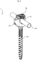
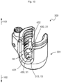
- Fig. 6a and 6b 1 shows another osteosynthesis device 1.
- the pressure piece 20 has open slots 26 in the distal direction 102.
- at least three spring-elastic arms 27 are formed on the head receiving area 29, wherein the spring-elastic arms 27 describe a cone 271 on their outer side, at least in sections, and the bone anchor 90 can be inserted into the fork head 10 from the distal direction 102. This allows bone anchors 90 with a larger outer diameter to be mounted to the fork head 10.
- At least one inner conical section 183 is defined in the ball receiving area 19, which is congruent with the cone 271 of the pressure piece 20 and, upon actuation of the locking element 60, leads to the angle-stable clamping of the bone anchor head area 91 with the fork head 10 ( Fig. 6a,b and Fig. 7 ).
- the pressure piece it is necessary for the pressure piece to have a lateral opening or at least a partial cutout 23 through which the fixing element 30 is guided and can move. This ensures that the pressure piece 20 is not loaded when the temporary clamping is activated.
- the fork head legs 11, 12 each provide a support surface 181 with an undercut that is effective in the proximal direction 101, and the pressure piece 20 has projections 24 directed radially outwards at the proximal end, wherein the projections 24 are designed to be resilient in the radial direction inwards, so that the pressure piece 20 can be inserted into the fork head 10 from the proximal direction 101.
- the projections of the pressure piece 24 engage with the support surfaces 181 and the pressure piece 20 is secured in the proximal direction 101 but not subjected to force.
- the fork head 10 has an area in the through-opening 18 which, at least in sections, has a larger inner diameter 182 than the core diameter of the thread 16. This makes it possible, if the pressure piece is not yet completely locked into the final position with the fork head 10, that the spring-elastic cone area 27 of the pressure piece in the fork head 10 at the level of the inner diameter extension 182 is provided with appropriate space for spreading for assembly with the bone anchor head area 91.
- Fig. 8 As shown, when the adjusting element 40 is part of the osteosynthesis device 1 and has a predetermined breaking point 45, only a part of the adjusting element 40 remains in the patient after the final locking with the connecting rod 50 and the locking element 60. The same picture arises when the adjusting element 40 is part of an instrument and is removed from the patient after the final locking with the connecting rod 50 and the locking element 60.
- the adjusting element 40 can also be provided completely as part of the osteosynthesis device 1. After the final locking with the connecting rod 50 and the locking element 60, it remains in the patient ( Fig. 9 . It is advantageous if the adjusting element 40 does not protrude beyond the proximal end 101 of the fork head 10.
- Fig. 10a shows an isometric view of a fastening system 300.
- the proximal end of the fastening system 300 is oriented upwards according to a proximal direction 101, and its distal end is oriented downwards according to a distal direction 102.
- the fastening system 300 has a main body 301. Proximally, the main body 301 has a first receiving area 310. Distally, the main body 301 has a second receiving area 319. Laterally distally, the main body 301 has a third receiving area 313. Laterally proximal, the main body 301 has an axial opening 14. An actuating element 40 is received in the axial opening 14.
- Fig. 10b shows an osteosynthesis device 1 with the Fig. 10a
- the fastening system 300 shown in an isometric view.
- the actuating element 40 is shown spaced apart from the axial opening 14 along the proximal direction 101, so that the proximal entrance of the axial opening 14 is visible.
- a bone anchor 90 is mounted in neutral position.
- the fastening system 300 is modular, i.e. the bone anchor 90 can be inserted or clicked in modularly ( Fig. 10b ) and removable again ( Fig. 10a ).
- Fig. 11 shows that in the Fig. 10a and 10b illustrated fastening system 300 in an exploded view.
- the fastening system 300 has a pressure piece 20, which is shown in the distal direction 101 above the first receiving area 310 of the main body 301.
- the pressure piece 20 has a first receiving area 325 in the proximal direction 101, which is equivalent to the first receiving area 310 of the main body 301.
- the pressure piece 20 further has a second receiving area 329 in the distal direction 102, which is equivalent to the first receiving area 310 of the main body 301.
- the pressure piece 20 laterally has a third receiving area 403, which is equivalent to the third receiving area 313 of the main body 301.
- the axial opening 14 has an internal thread 314, the proximal area of which can be seen here.
- the axial opening 14 further comprises a compression opening 401 positioned at the distal end of the internal thread 314.
- the fastening system 300 further comprises a fixing element 30.
- the fixing element 30 has a load-bearing region 332 and a contact region 32 on the side and proximally, respectively.
- the fixing element 30 further comprises a first fixing pin 431.
- Fig. 12a shows the Fig. 10b 1 shows an osteosynthesis device 1 shown in a side view with a sectional plane.
- the sectional plane runs centrally through the osteosynthesis device 1 as well as centrally through the adjusting element 40 and the bone anchor 90.
- the axial opening 14 further comprises a second compression opening 401. Both compression openings 401 are positioned laterally on the axial opening 14.
- the distal region of the internal thread 314 of the axial opening 14, for example its last thread turn, can be compressed through these two compression openings 401.
- the adjusting element 40 has a load introduction region 344 or contact region 44 distally (see distal direction 102).
- the load introduction region 344 is in contact or engagement with the load-bearing region 332 of the fixing element 30.
- the axial opening 14 is limited along the distal direction 102 in such a way, or the distal end is such a way positioned so that the second receiving area 319 of the main body 301 is accessible from the outside. If the adjusting element 40 is screwed into the axial opening 14 until the proximal end of the adjusting element 40 comes close to the proximal end of the axial opening 14, the distal end of the adjusting element 40 protrudes from the axial opening 14, i.e., is positioned further along the distal direction 102 than the distal end of the axial opening (see also Fig. 12b ). In this way, the adjusting element 40 functions via its distal end as a loss prevention device for the fixing element 30.
- Fig. 12b shows the Fig. 10b and 12a shown osteosynthesis device 1 in a sectional view CC along the also shown Fig. 12a shown sectional plane.
- the sectional plane runs centrally through the osteosynthesis device 1 as well as centrally through the actuating element 40 and the bone anchor 90.
- the pressure piece 20 is received in the first receiving area 310 such that the first receiving area 310 of the main body 301 and the first receiving area 325 of the pressure piece 20 as well as the second receiving area 319 of the main body 301 and the first receiving area 329 of the pressure piece 20 complement one another.
- the main body 301 has a first fork leg 11, which has a threaded section 315, and a second fork leg 12, which has a threaded section 316. Both threaded sections 315 and 316 are complementary to one another.
- a central axis 103 is shown, which runs centrally through the main body 301 or its first receiving area 310 and the second receiving area 319 of the main body 301, as well as centrally through the second receiving area 329 of the pressure piece 20 and the bone anchor 90 positioned in the neutral position.
- a fixation element axis 130 is also shown, which runs longitudinally along the third receiving area 313 and the fixation element 30 received therein.
- the bone anchor 90 has a head area 91 towards the proximal end (compare proximal direction 101).
- the bone anchor 90 or its head area 91 is received in the second receiving area 329 of the pressure piece and in the second receiving area 319 of the main body 301 in the fastening system 300.
- the third receiving area 313 has a transverse opening 13 in which the fixation element 30 is received or mounted.
- the third receiving area 313 is offset relative to the first receiving area 310 and the second receiving area 319, i.e., deviating from the axis extending from proximal to distal. The offset is determined by the rotation of the fixation element axis 130 around a point in the head area 91.
- the central axis 103 and the fixing element axis 130 span an angle W.
- the angle W can - provided the adjusting element 40 impinges on the fixing element 30 from the proximal side - theoretically lie in the range from 0° to 90°, whereby it is preferably in the range from 20° to 80°.
- the smaller the angle W the less space is required, in particular for the axial opening 14 and the third receiving area 313 of the main body 301.
- the larger the angle W the greater the clamping effect that can be generated with the fixing element 30 on the bone anchor 90 or its head area 91.
- Fig. 13a shows an isometric view of a fixing element 30 with a first fixing pin 431 and a second fixing pin 432.
- the first fixing pin 431 and the second fixing pin 432 are each rounded on the outside.
- the first fixing pin 431 and the second fixing pin 432 each have a contact surface 430 at their distal end.
- a free space 434 is located between the first fixing pin 431 and the second fixing pin 432.
- Fig. 13b shows that in Fig. 13a
- the fixation element 30 shown in a side view.
- the fixation element 30 is distal-proximal as shown in the Fig. 12a and 12b
- the contact surfaces 430 are chamfered so that despite the fixing element 30 being offset by the angle W (compare Fig. 12b ) these contact surfaces 430 touch the bone anchor 90 or its head region 91 over a large area.
- the contact surfaces 430 are also designed to be beveled inwards, i.e. in the direction of the free space 434. Both of the aforementioned bevels, i.e.
- the load-bearing region 332 or contact region 32 shown on the left is designed or oriented essentially perpendicular to the main direction of the fixing element 30, i.e. perpendicular to the fixing element axis 130.
- the contact surfaces 430 can be formed with an increased surface roughness, as is the case, for example, with the contact area 31 of the Fig. 5a and 5b illustrated fixing element 30.
- Fig. 13c shows that in the Fig. 13a and 13b shown fixing element 30 in a top view.
- Fig. 13d shows that in the Fig. 13a to 13c shown fixing element 30 from below.
- the fixing element 30 is in both Fig. 13c and 13d distal-proximal as in the Fig. 12a, 12b , 13a and 13b shown aligned.
- Fig. 14a shows an adjusting element 40 in engagement with the Fig. 13a to 13d illustrated fixation element 30 and a bone anchor 90 in an isometric view.
- the fixation element 30 has an external thread 343, which is complementary to the internal thread 314 of the axial opening 14 (compare, for example, Fig. 12b ).
- the actuating element 40 is screwed into the axial opening 14 (not shown here) in such a way that the load introduction area 344 or contact area 44 is in engagement with the load receiving area 332 or contact area 32 (compare, for example, Fig. 12b ). This results in an effective direction 601 along an actuating element axis 140 with respect to the actuating element 40.
- This effective direction 601 runs parallel to the central axis 103, since this in turn runs parallel to the axial opening 14 (compare Fig. 12b ), and rectified to the distal direction 102.
- the load is transferred from the adjusting element 40 to the fixing element 30, whereby the direction of action 602 results from the orientation of the fixing element 30, i.e., following the fixing element axis 130 with respect to the fixing element 30.
- the contact surfaces 430 are pressed onto the bone anchor 90 or its head area 91 (cf. Fig. 13a ).
- Fig. 14b shows a top view of a fixation element 30 with a first fixation pin 431 engaging a head region 91 of a bone anchor 90.
- the fixation element 30 is pressed onto the head region 91 in such a way that its first fixation pin 431 or the contact surface 430/the contact region 31 is pressed onto the head region 91, resulting in an effective direction 602 that is substantially perpendicular to the contact surface 430 or the contact region 31.
- the head region 91 is pressed into the second receiving region 319 of the main body 301 or into the second receiving region 329 of the pressure piece 20 (both not shown here, but compare Fig. 3 and 12b ), resulting in an effective direction 603 opposite to the effective direction 602.
- the opposing effective directions 602 and 603 extend along an effective axis 611, which runs centrally through the head region 91. In this way, a secure clamping effect is generated via a two-point clamping.
- Fig. 14c shows that in the Fig. 13a to 13d shown fixing element 30 in the Fig. 14a shown engagement position with the head region 91 of the bone anchor 90 in a top view.
- the fixing element 30 is pressed onto the head region 91.
- the effective direction 606 results with respect to the first fixing pin 431 and the effective direction 604 with respect to the second fixing pin 432.
- These two effective directions 604, 606 are oriented essentially perpendicular to/to the respective contact surface 430/contact region 31.
- the head region 91 is pressed into the second receiving region 319 of the main body 301 or into the second receiving region 329 of the pressure piece 20 (both not shown here, but compare 12b), resulting in an effective direction 605 (opposite to the effective direction 604), 607 (opposite to the effective direction 606) opposite to the effective directions 604, 606.
- These two effective directions 605, 607 also result on the side of the head region 91 opposite the starting points of the effective directions 604, 606.
- the opposing effective directions 604 and 605 as well as 606 and 607 each run on an effective axis 612 (corresponding to the effective directions 604 and 605) and 613 (effective directions 606 and 607), which each run decentrally through the head region 91.
- the two effective directions 605 and 607 start in the same area of the head region 91. In this way, a secure clamping effect is generated via a three-point clamping, which, compared to the Fig. 14b The clamping effect shown is further enhanced.
- Fig. 15 shows that in Fig. 10a illustrated fastening system 300 in another isometric view. In this illustration, no pressure piece 20 is shown. Furthermore, the distal end of the third receiving area 313 of the main body 301 or the distal end of the transverse opening 13 is shown, from which the distal End of the fixing element 30 protrudes or whose contact surfaces 430/contact areas 31 protrude.
- the outer contour of the fixing element 30 (compare Fig. 13a ), the inner contour of the transverse opening 13 is approximately designed as an elongated hole in cross-section. To enable secure guidance of the fixing element 30, this cross-section of the transverse opening 13 is constant from proximal to distal (see also Fig. 12a ).
- Fig. 16a shows that in the Fig. 13a to 13d illustrated fixing element 30 in engagement with a pressure piece 20 in an isometric view.
- the pressure piece 20 has a plurality of spring elements 327, for example four spring elements 327 distributed radially.
- the first receiving area 325 of the pressure piece 20 is tapered in the proximal direction 101.
- the fixing element 30 is also in the Fig. 12a, 12b , 13a and 13b shown distal-proximal orientation.
- Fig. 16b shows that in Fig. 16a shown fixing element 30 in the also shown Fig. 16a shown engagement position with the pressure piece 20 in a side view with a sectional plane.
- the fixing element 30 is in the third receiving area 403 of the pressure piece 20 in the Fig. 12a, 12b , 13a, 13b and 16a shown distal-proximal alignment.
- Three spring elements 327 can be seen here, whereby the pressure piece 20 further has a fourth spring element 327, which is covered by the spring element 327 shown in the center (see Fig. 16c ).
- the spring element 327 shown on the left is located in the third receiving area 403.
- Fig. 16c shows that in the Fig. 16a and 16b shown fixing element 30 in the also shown in the Fig. 16a and 16b shown engagement position with the pressure piece 20 in a sectional view DD along the also shown Fig. 16b shown sectional plane.
- the spring element 327 arranged in the third receiving area 403 is designed such that the first fixing pin 431 and the second fixing pin 432 can slide past it without this spring element 327 coming into force-locking connection with the first fixing pin 431 and/or the second fixing pin 432.
- the spring element 327 arranged in the third receiving area 403 thickens below the first fixing pin 431 and the second fixing pin 432.
- the spring element 327 arranged in the third receiving area 403 thickens in the proximal direction 101 above the first fixing pin 431 and the second fixing pin 432.
- the spring element 327 arranged in the third receiving area 403 conceals in the Fig. 16c shown view the free space 434 or slides into it (compare for example Fig. 13a ). In this way, the pressure piece 20 is also secured against loss by the fixing element 30.
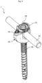
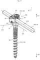
- Fig. 17 shows the Fig. 10b , 12a and 12b Illustrated osteosynthesis device 1 with a connecting element 350 in an isometric view.
- the connecting element 350 is designed as a connecting rod 50.
- the connecting rod 50 is rotationally symmetrical.
- the connecting rod 50 is received in the first receiving area 310 of the main body 301 as well as in the first receiving area 325 of the pressure piece 20 and secured or pre-secured by means of a locking element 60. If the locking element 60 were to be tightened further, the connecting rod 50 would be further pulled onto the pressure piece 20 (not visible here, compare Fig. 12b ) and ultimately a final fixation of the bone anchor 90 is achieved.
- lateral fixation with respect to the fastening system 300 is illustrated here by an effective axis 616, which runs parallel to or along the longitudinal axis of the connecting rod 50. Shown here, however, is the state of pre-fixation, as it is achieved by tightening the adjusting element 40 and thereby pressing the fixing element 30 onto the head region 91 (not visible here, compare Fig. 12b ) is achieved and is based on the overall view of the Fig.
- the three-point clamping shown results in three mutually perpendicular axes of action 613, 614, 615 with respect to the head region 91 and bone anchor 90, respectively, which span a clamping effective space within which the bone anchor 90 is pre-fixed with respect to its orientation and position relative to the fastening system 300.
- the three axes of action 613, 614, 615 intersect in the head region 91.
- the axis of action 614 runs at least partially congruent with the central axis 103.
- the axis of action 615 runs parallel to the axis of action 616.
- the axis of action 613 runs perpendicular to the axes of action 614 and 615 and through the head region 91.
- the Fig. 17 The clamping effect achieved in the pre-fixing shown is achieved in particular along the longitudinal axis of the connecting rod 50, which is represented by the effective axis 615 as described above.
- the clamping effect along and in the direction of the effective axis 615, i.e. along the longitudinal axis of the connecting rod 50, is reinforced.
Landscapes
- Health & Medical Sciences (AREA)
- Orthopedic Medicine & Surgery (AREA)
- Neurology (AREA)
- Life Sciences & Earth Sciences (AREA)
- Surgery (AREA)
- Heart & Thoracic Surgery (AREA)
- Engineering & Computer Science (AREA)
- Biomedical Technology (AREA)
- Nuclear Medicine, Radiotherapy & Molecular Imaging (AREA)
- Medical Informatics (AREA)
- Molecular Biology (AREA)
- Animal Behavior & Ethology (AREA)
- General Health & Medical Sciences (AREA)
- Public Health (AREA)
- Veterinary Medicine (AREA)
- Surgical Instruments (AREA)
Claims (14)
- Système de fixation (300) pour un dispositif d'ostéosynthèse (1) pour le traitement de la colonne vertébrale, comprenant un corps principal (301)doté d'une première zone de réception (310), qui est conçue pour recevoir un élément de liaison (350) et qui est conçue comme une chape (10) en forme de U, qui présente une première branche de chape (11) et une seconde branche de chape (12).une deuxième zone de réception (319) qui est conçue pour recevoir un ancrage osseux (90),une troisième zone de réception (313) comprenant une ouverture transversale linéaire (13), dans lequel l'ouverture transversale (13) comprend une première ouverture (501) à sa première extrémité et une seconde ouverture (502) à sa seconde extrémité, etune ouverture axiale (14) pour recevoir et guider un élément de réglage (40), comprenant en outre un élément de fixation (30) pour fixer l'ancrage osseux (90), comprenant une première tige de fixation (431), et une partie de réception de charge (332), dans lequel la première tige de fixation (431) peut être insérée dans l'ouverture transversale (13) via la première ouverture (501), et l'élément de fixation (30) est plus long que l'ouverture transversale (13), et dans lequel la première tige de fixation (431) présente une surface de contact (430) à son extrémité éloignée de la zone de réception de charge (332), etun élément de réglage (40) comprenant une zone d'introduction de charge (344), dans lequel l'élément de réglage (40) peut être positionné et guidé au moyen de l'ouverture axiale (14) de telle sorte qu'au moyen de la pression exercée par la zone d'introduction de charge (344) sur la zone de réception de charge (332), l'élément de fixation (30) peut être guidé le long de l'ouverture transversale (13) en direction de la deuxième zone de réception (319).
- Système de fixation (300) selon la revendication 1, dans lequel la troisième zone de réception (313) est conçue de telle sorte que l'ouverture transversale (13) est prévue avec un décalage par rapport à l'axe central (103) de l'ancrage osseux (90) reçu en position neutre dans la deuxième zone de réception (319), dans lequel le décalage est d'au moins 20°, de préférence 30° et de manière particulièrement préférée 40° ainsi que de 80° au maximum, de préférence 70° et de manière particulièrement préférée 60°.
- Système de fixation (300) selon l'une des revendications précédentes, dans lequel la zone d'introduction de charge (344) et la zone de réception de charge (332) sont complémentaires l'une de l'autre.
- Système de fixation (300) selon l'une des revendications précédentes, dans lequel le système de fixation (300) comprend en outre une pièce de pression (20), dans lequel la pièce de pression (20) comprend une première zone de réception (325) équivalente à la première zone de réception (310) du système de fixation (300), une deuxième zone de réception (329) équivalente à la deuxième zone de réception (319) du système de fixation (300) et présentant plusieurs éléments élastiques (327) ainsi qu'une troisième zone de réception (403) équivalente à la troisième zone de réception (313) du corps principal (301) et présentant une ouverture transversale linéaire (323), et dans lequel la pièce de pression (20) peut être insérée dans le corps principal (300) via la première zone de réception (310) du corps principal (301).
- Système de fixation (300) selon l'une des revendications précédentes, dans lequel l'ouverture axiale (14) présente un filetage intérieur (314) et l'élément de réglage (40) présente un filetage extérieur (343), et dans lequel le filetage intérieur (314) de l'ouverture axiale (14) est complémentaire du filetage extérieur (343) de l'élément de réglage (40), dans lequel, en particulier, le filetage intérieur (314) de l'ouverture axiale (14) s'étend sensiblement parallèlement à l'axe central (103) de l'ancrage osseux (90) reçu en position neutre dans la deuxième zone de réception (319).
- Système de fixation (300) selon la revendication 5, dans lequel l'ouverture axiale (14) présente au moins une ouverture d'enfoncement (401), dans lequel l'ouverture d'enfoncement (401) est positionnée à l'extrémité distale du filetage intérieur (314), et dans lequel l'ouverture d'enfoncement (401) est réalisée de telle sorte qu'un enfoncement du filetage extérieur (343) de l'élément de réglage (40) est rendu possible par l'intermédiaire de celle-ci.
- Système de fixation (300) selon l'une des revendications précédentes, dans lequel l'élément de fixation (30) comprend en outre une seconde tige de fixation (432).
- Système de fixation (300) selon l'une des revendications précédentes, dans lequel la surface de contact (430) de la première tige de fixation (431) ou, le cas échéant, de la première et/ou de la seconde tige de fixation (432) est complémentaire d'une surface de contact correspondante (430) de l'ancrage osseux (90).
- Système de fixation (300) selon la revendication 7 et l'une des revendications 4, ou 5, 6 ou 8 en combinaison avec la revendication 4, dans lequel un élément élastique (327) est disposé dans l'ouverture linéaire transversale (323) de la pièce de pression (20), et dans lequel cet élément élastique (327) est placé notamment au centre de l'ouverture linéaire transversale (323).
- Système de fixation (300) selon la revendication 9, dans lequel l'élément élastique (327) disposé dans l'ouverture transversale linéaire (323) est réalisé de manière à s'élargir dans la zone distale.
- Système de fixation (300) selon l'une des revendications précédentes, dans lequel la surface de contact (430) de la première tige de fixation (431) ou, le cas échéant, de la première et/ou de la seconde tige de fixation (431, 432) présente une rugosité de surface localement accrue.
- Système de fixation (300) selon l'une quelconque des revendications précédentes, dans lequel la première zone de réception (310) du corps principal (301) comporte un filetage (16).
- Système de fixation (300) selon la revendication 12, dans lequel la troisième zone de réception (313) et l'ouverture axiale (14) sont disposées sur la première branche de chape (11).
- Dispositif d'ostéosynthèse (1), notamment pour le traitement de la colonne vertébrale, comprenant un ancrage osseux (90) et un système de fixation (300) selon l'une des revendications précédentes.
Applications Claiming Priority (3)
| Application Number | Priority Date | Filing Date | Title |
|---|---|---|---|
| DE102021001896 | 2021-04-13 | ||
| DE102022108980.0A DE102022108980A1 (de) | 2021-04-13 | 2022-04-12 | Osteosynthesevorrichtung insbesondere zur Wirbelsäulenbehandlung und Befestigungssystem für diese |
| PCT/EP2022/059942 WO2022219077A1 (fr) | 2021-04-13 | 2022-04-13 | Dispositif d'ostéosynthèse, en particulier pour le traitement de la colonne vertébrale et système de fixation associé |
Publications (3)
| Publication Number | Publication Date |
|---|---|
| EP4322875A1 EP4322875A1 (fr) | 2024-02-21 |
| EP4322875C0 EP4322875C0 (fr) | 2025-04-02 |
| EP4322875B1 true EP4322875B1 (fr) | 2025-04-02 |
Family
ID=81654721
Family Applications (1)
| Application Number | Title | Priority Date | Filing Date |
|---|---|---|---|
| EP22723556.1A Active EP4322875B1 (fr) | 2021-04-13 | 2022-04-13 | Dispositif d'ostéosynthèse pour le traitement de la colonne vertébrale et système de fixation associé |
Country Status (7)
| Country | Link |
|---|---|
| US (1) | US20240122628A1 (fr) |
| EP (1) | EP4322875B1 (fr) |
| JP (1) | JP2024513591A (fr) |
| KR (1) | KR20240004293A (fr) |
| AU (1) | AU2022258666A1 (fr) |
| DE (1) | DE102022108980A1 (fr) |
| WO (1) | WO2022219077A1 (fr) |
Families Citing this family (3)
| Publication number | Priority date | Publication date | Assignee | Title |
|---|---|---|---|---|
| EP4429572A1 (fr) * | 2021-11-11 | 2024-09-18 | Orthofix US LLC | Dispositifs et ensembles implantables à ajustement serré |
| EP4371511B1 (fr) * | 2022-11-15 | 2025-03-05 | Biedermann Technologies GmbH & Co. KG | Dispositif de couplage pour coupler une tige à un élément d'ancrage osseux |
| WO2025150754A1 (fr) | 2024-01-10 | 2025-07-17 | 주식회사 엘지에너지솔루션 | Appareil de commande de système pour système d'alimentation, et son procédé de commande |
Family Cites Families (9)
| Publication number | Priority date | Publication date | Assignee | Title |
|---|---|---|---|---|
| US7789897B2 (en) * | 2006-04-11 | 2010-09-07 | Warsaw Orthopedic, Inc. | Pedicle screw spinal rod connector arrangement |
| US8361129B2 (en) * | 2006-04-28 | 2013-01-29 | Depuy Spine, Inc. | Large diameter bone anchor assembly |
| EP1923011B1 (fr) * | 2006-11-17 | 2009-10-07 | BIEDERMANN MOTECH GmbH | Dispositif d'ancrage osseux |
| US7942909B2 (en) * | 2009-08-13 | 2011-05-17 | Ortho Innovations, Llc | Thread-thru polyaxial pedicle screw system |
| EP2502594B1 (fr) * | 2011-03-22 | 2014-12-03 | Medacta International S.A. | Vis de pédicule polyaxial et kit de système de fixation comprenant ladite vis |
| DE102011053295A1 (de) | 2011-09-06 | 2013-03-07 | Aesculap Ag | Polyaxiale Pedikelschraube mit provisorischer Fixierung |
| WO2015155702A1 (fr) * | 2014-04-10 | 2015-10-15 | Medacta International Sa | Dispositif permettant de fixer des implants chirurgicaux en place et procédure d'assemblage associée comprenant un moyen d'ancrage |
| DE102016114266B4 (de) * | 2016-08-02 | 2018-02-15 | Silony Medical International AG | Polyaxialpedikelschraube |
| DE102018102173B3 (de) | 2018-01-31 | 2019-06-13 | Silony Medical International AG | Polyaxialschraube |
-
2022
- 2022-04-12 DE DE102022108980.0A patent/DE102022108980A1/de active Pending
- 2022-04-13 EP EP22723556.1A patent/EP4322875B1/fr active Active
- 2022-04-13 US US18/555,217 patent/US20240122628A1/en active Pending
- 2022-04-13 WO PCT/EP2022/059942 patent/WO2022219077A1/fr not_active Ceased
- 2022-04-13 AU AU2022258666A patent/AU2022258666A1/en not_active Abandoned
- 2022-04-13 JP JP2023563012A patent/JP2024513591A/ja active Pending
- 2022-04-13 KR KR1020237034756A patent/KR20240004293A/ko not_active Ceased
Also Published As
| Publication number | Publication date |
|---|---|
| EP4322875C0 (fr) | 2025-04-02 |
| JP2024513591A (ja) | 2024-03-26 |
| EP4322875A1 (fr) | 2024-02-21 |
| US20240122628A1 (en) | 2024-04-18 |
| KR20240004293A (ko) | 2024-01-11 |
| DE102022108980A1 (de) | 2022-10-13 |
| WO2022219077A1 (fr) | 2022-10-20 |
| AU2022258666A1 (en) | 2023-11-23 |
Similar Documents
| Publication | Publication Date | Title |
|---|---|---|
| EP4322875B1 (fr) | Dispositif d'ostéosynthèse pour le traitement de la colonne vertébrale et système de fixation associé | |
| EP3117787B1 (fr) | Vis pediculaire avec tulipe | |
| DE60108662T2 (de) | Verbindungsvorrichtung für variable winkel in einem spinalimplantatsystem | |
| DE69520105T2 (de) | Modularer intramedullarnagel | |
| DE69716471T2 (de) | Formgedächtnistechnik benutzende vielwinkel-knochenschraubenanordnung | |
| EP2328518B1 (fr) | Implant pour arthrodèse du genou | |
| EP1287787B1 (fr) | Implant pour fixation des fractures osseuses | |
| DE9490219U1 (de) | Gesperre-Kompressionsvorrichtung | |
| EP2515779A1 (fr) | Système de plaques osseuses pour ostéosynthèse | |
| EP0736286A2 (fr) | Instrument auxiliaire pour ostéosynthèse permettant de traiter des fractures subtrochantériennes et pertrochantériennes, ainsi que des fractures du col du fémur | |
| EP2906131B1 (fr) | Agencement de fixation de vis à os sécurisées pour ne pas se fausser en tournant | |
| EP3923840B1 (fr) | Dispositif d'ancrage osseux pour l'abord pédiculaire | |
| EP2460481A1 (fr) | Implant de fusion pour articulations à facettes | |
| EP3023066B1 (fr) | Système de vis pédiculaire et système de stabilisation de colonne vertébrale | |
| EP1416868A1 (fr) | Dispositif d'osteosynthese intramedullaire pour reparer des fractures laterales s'etendant vers le centre du femur | |
| DE102020003247A1 (de) | Modulare Osteosynthesevorrichtung für Wirbel | |
| EP4216848B1 (fr) | Dispositif d'ostéosynthèse modulaire et à fixation temporaire pour vertèbres | |
| EP4326177B1 (fr) | Dispositif d'ostéosynthèse à fixation temporaire pour vertèbres, avec un élément de fixation rotatif | |
| WO2014111555A1 (fr) | Système d'implant et élément de fixation pour un système d'implant | |
| DE102004056091B4 (de) | Orthopädische Fixationsvorrichtung und orthopädisches Fixationssystem | |
| DE9310668U1 (de) | Schraubendreher | |
| DE19829699A1 (de) | Osteosynthetische Befestigungsvorrichtung | |
| DE202021004049U1 (de) | Temporär fixierbare Osteosynthesevorrichtung für Wirbel | |
| EP4051143A1 (fr) | Instrument de découplage pour usage médical | |
| DE202019005511U1 (de) | Knochenverankerungsvorrichtung für den Pedikelzugang |
Legal Events
| Date | Code | Title | Description |
|---|---|---|---|
| STAA | Information on the status of an ep patent application or granted ep patent |
Free format text: STATUS: UNKNOWN |
|
| STAA | Information on the status of an ep patent application or granted ep patent |
Free format text: STATUS: THE INTERNATIONAL PUBLICATION HAS BEEN MADE |
|
| PUAI | Public reference made under article 153(3) epc to a published international application that has entered the european phase |
Free format text: ORIGINAL CODE: 0009012 |
|
| STAA | Information on the status of an ep patent application or granted ep patent |
Free format text: STATUS: REQUEST FOR EXAMINATION WAS MADE |
|
| 17P | Request for examination filed |
Effective date: 20231113 |
|
| AK | Designated contracting states |
Kind code of ref document: A1 Designated state(s): AL AT BE BG CH CY CZ DE DK EE ES FI FR GB GR HR HU IE IS IT LI LT LU LV MC MK MT NL NO PL PT RO RS SE SI SK SM TR |
|
| DAV | Request for validation of the european patent (deleted) | ||
| DAX | Request for extension of the european patent (deleted) | ||
| GRAP | Despatch of communication of intention to grant a patent |
Free format text: ORIGINAL CODE: EPIDOSNIGR1 |
|
| STAA | Information on the status of an ep patent application or granted ep patent |
Free format text: STATUS: GRANT OF PATENT IS INTENDED |
|
| INTG | Intention to grant announced |
Effective date: 20241024 |
|
| GRAS | Grant fee paid |
Free format text: ORIGINAL CODE: EPIDOSNIGR3 |
|
| GRAA | (expected) grant |
Free format text: ORIGINAL CODE: 0009210 |
|
| STAA | Information on the status of an ep patent application or granted ep patent |
Free format text: STATUS: THE PATENT HAS BEEN GRANTED |
|
| AK | Designated contracting states |
Kind code of ref document: B1 Designated state(s): AL AT BE BG CH CY CZ DE DK EE ES FI FR GB GR HR HU IE IS IT LI LT LU LV MC MK MT NL NO PL PT RO RS SE SI SK SM TR |
|
| REG | Reference to a national code |
Ref country code: GB Ref legal event code: FG4D Free format text: NOT ENGLISH |
|
| REG | Reference to a national code |
Ref country code: CH Ref legal event code: EP |
|
| REG | Reference to a national code |
Ref country code: IE Ref legal event code: FG4D Free format text: LANGUAGE OF EP DOCUMENT: GERMAN |
|
| REG | Reference to a national code |
Ref country code: DE Ref legal event code: R096 Ref document number: 502022003442 Country of ref document: DE |
|
| U01 | Request for unitary effect filed |
Effective date: 20250502 |
|
| U07 | Unitary effect registered |
Designated state(s): AT BE BG DE DK EE FI FR IT LT LU LV MT NL PT RO SE SI Effective date: 20250508 |
|
| U20 | Renewal fee for the european patent with unitary effect paid |
Year of fee payment: 4 Effective date: 20250506 |
|
| PGFP | Annual fee paid to national office [announced via postgrant information from national office to epo] |
Ref country code: CH Payment date: 20250501 Year of fee payment: 4 |
|
| PG25 | Lapsed in a contracting state [announced via postgrant information from national office to epo] |
Ref country code: ES Free format text: LAPSE BECAUSE OF FAILURE TO SUBMIT A TRANSLATION OF THE DESCRIPTION OR TO PAY THE FEE WITHIN THE PRESCRIBED TIME-LIMIT Effective date: 20250402 |
|
| PG25 | Lapsed in a contracting state [announced via postgrant information from national office to epo] |
Ref country code: GR Free format text: LAPSE BECAUSE OF FAILURE TO SUBMIT A TRANSLATION OF THE DESCRIPTION OR TO PAY THE FEE WITHIN THE PRESCRIBED TIME-LIMIT Effective date: 20250703 Ref country code: NO Free format text: LAPSE BECAUSE OF FAILURE TO SUBMIT A TRANSLATION OF THE DESCRIPTION OR TO PAY THE FEE WITHIN THE PRESCRIBED TIME-LIMIT Effective date: 20250702 |
|
| PG25 | Lapsed in a contracting state [announced via postgrant information from national office to epo] |
Ref country code: PL Free format text: LAPSE BECAUSE OF FAILURE TO SUBMIT A TRANSLATION OF THE DESCRIPTION OR TO PAY THE FEE WITHIN THE PRESCRIBED TIME-LIMIT Effective date: 20250402 |
|
| PG25 | Lapsed in a contracting state [announced via postgrant information from national office to epo] |
Ref country code: HR Free format text: LAPSE BECAUSE OF FAILURE TO SUBMIT A TRANSLATION OF THE DESCRIPTION OR TO PAY THE FEE WITHIN THE PRESCRIBED TIME-LIMIT Effective date: 20250402 |
|
| PG25 | Lapsed in a contracting state [announced via postgrant information from national office to epo] |
Ref country code: RS Free format text: LAPSE BECAUSE OF FAILURE TO SUBMIT A TRANSLATION OF THE DESCRIPTION OR TO PAY THE FEE WITHIN THE PRESCRIBED TIME-LIMIT Effective date: 20250702 |
|
| PG25 | Lapsed in a contracting state [announced via postgrant information from national office to epo] |
Ref country code: IS Free format text: LAPSE BECAUSE OF FAILURE TO SUBMIT A TRANSLATION OF THE DESCRIPTION OR TO PAY THE FEE WITHIN THE PRESCRIBED TIME-LIMIT Effective date: 20250802 |
|
| PG25 | Lapsed in a contracting state [announced via postgrant information from national office to epo] |
Ref country code: SM Free format text: LAPSE BECAUSE OF FAILURE TO SUBMIT A TRANSLATION OF THE DESCRIPTION OR TO PAY THE FEE WITHIN THE PRESCRIBED TIME-LIMIT Effective date: 20250402 |
|
| PG25 | Lapsed in a contracting state [announced via postgrant information from national office to epo] |
Ref country code: CZ Free format text: LAPSE BECAUSE OF FAILURE TO SUBMIT A TRANSLATION OF THE DESCRIPTION OR TO PAY THE FEE WITHIN THE PRESCRIBED TIME-LIMIT Effective date: 20250402 |
|
| PG25 | Lapsed in a contracting state [announced via postgrant information from national office to epo] |
Ref country code: SK Free format text: LAPSE BECAUSE OF FAILURE TO SUBMIT A TRANSLATION OF THE DESCRIPTION OR TO PAY THE FEE WITHIN THE PRESCRIBED TIME-LIMIT Effective date: 20250402 |
|
| PG25 | Lapsed in a contracting state [announced via postgrant information from national office to epo] |
Ref country code: MC Free format text: LAPSE BECAUSE OF FAILURE TO SUBMIT A TRANSLATION OF THE DESCRIPTION OR TO PAY THE FEE WITHIN THE PRESCRIBED TIME-LIMIT Effective date: 20250402 |
|
| PLBE | No opposition filed within time limit |
Free format text: ORIGINAL CODE: 0009261 |
|
| STAA | Information on the status of an ep patent application or granted ep patent |
Free format text: STATUS: NO OPPOSITION FILED WITHIN TIME LIMIT |
|
| REG | Reference to a national code |
Ref country code: CH Ref legal event code: L10 Free format text: ST27 STATUS EVENT CODE: U-0-0-L10-L00 (AS PROVIDED BY THE NATIONAL OFFICE) Effective date: 20260211 |
|
| 26N | No opposition filed |
Effective date: 20260105 |
|
| PGFP | Annual fee paid to national office [announced via postgrant information from national office to epo] |
Ref country code: GB Payment date: 20260327 Year of fee payment: 5 |
|
| PG25 | Lapsed in a contracting state [announced via postgrant information from national office to epo] |
Ref country code: IE Free format text: LAPSE BECAUSE OF NON-PAYMENT OF DUE FEES Effective date: 20250413 |