EP4323371B1 - Composé de coordination organométallique et son procédé de production - Google Patents
Composé de coordination organométallique et son procédé de production Download PDFInfo
- Publication number
- EP4323371B1 EP4323371B1 EP21820253.9A EP21820253A EP4323371B1 EP 4323371 B1 EP4323371 B1 EP 4323371B1 EP 21820253 A EP21820253 A EP 21820253A EP 4323371 B1 EP4323371 B1 EP 4323371B1
- Authority
- EP
- European Patent Office
- Prior art keywords
- organic
- group
- groups
- monoanionic
- cyclic
- Prior art date
- Legal status (The legal status is an assumption and is not a legal conclusion. Google has not performed a legal analysis and makes no representation as to the accuracy of the status listed.)
- Active
Links
Images





























































Classifications
-
- A—HUMAN NECESSITIES
- A61—MEDICAL OR VETERINARY SCIENCE; HYGIENE
- A61K—PREPARATIONS FOR MEDICAL, DENTAL OR TOILETRY PURPOSES
- A61K49/00—Preparations for testing in vivo
- A61K49/06—Nuclear magnetic resonance [NMR] contrast preparations; Magnetic resonance imaging [MRI] contrast preparations
- A61K49/08—Nuclear magnetic resonance [NMR] contrast preparations; Magnetic resonance imaging [MRI] contrast preparations characterised by the carrier
- A61K49/10—Organic compounds
- A61K49/101—Organic compounds the carrier being a complex-forming compound able to form MRI-active complexes with paramagnetic metals
-
- A—HUMAN NECESSITIES
- A61—MEDICAL OR VETERINARY SCIENCE; HYGIENE
- A61K—PREPARATIONS FOR MEDICAL, DENTAL OR TOILETRY PURPOSES
- A61K49/00—Preparations for testing in vivo
- A61K49/06—Nuclear magnetic resonance [NMR] contrast preparations; Magnetic resonance imaging [MRI] contrast preparations
- A61K49/08—Nuclear magnetic resonance [NMR] contrast preparations; Magnetic resonance imaging [MRI] contrast preparations characterised by the carrier
- A61K49/10—Organic compounds
- A61K49/101—Organic compounds the carrier being a complex-forming compound able to form MRI-active complexes with paramagnetic metals
- A61K49/106—Organic compounds the carrier being a complex-forming compound able to form MRI-active complexes with paramagnetic metals the complex-forming compound being cyclic, e.g. DOTA
-
- C—CHEMISTRY; METALLURGY
- C07—ORGANIC CHEMISTRY
- C07F—ACYCLIC, CARBOCYCLIC OR HETEROCYCLIC COMPOUNDS CONTAINING ELEMENTS OTHER THAN CARBON, HYDROGEN, HALOGEN, OXYGEN, NITROGEN, SULFUR, SELENIUM OR TELLURIUM
- C07F5/00—Compounds containing elements of Groups 3 or 13 of the Periodic Table
- C07F5/003—Compounds containing elements of Groups 3 or 13 of the Periodic Table without C-Metal linkages
-
- C—CHEMISTRY; METALLURGY
- C07—ORGANIC CHEMISTRY
- C07F—ACYCLIC, CARBOCYCLIC OR HETEROCYCLIC COMPOUNDS CONTAINING ELEMENTS OTHER THAN CARBON, HYDROGEN, HALOGEN, OXYGEN, NITROGEN, SULFUR, SELENIUM OR TELLURIUM
- C07F5/00—Compounds containing elements of Groups 3 or 13 of the Periodic Table
- C07F5/02—Boron compounds
- C07F5/027—Organoboranes and organoborohydrides
-
- C—CHEMISTRY; METALLURGY
- C07—ORGANIC CHEMISTRY
- C07F—ACYCLIC, CARBOCYCLIC OR HETEROCYCLIC COMPOUNDS CONTAINING ELEMENTS OTHER THAN CARBON, HYDROGEN, HALOGEN, OXYGEN, NITROGEN, SULFUR, SELENIUM OR TELLURIUM
- C07F9/00—Compounds containing elements of Groups 5 or 15 of the Periodic Table
- C07F9/02—Phosphorus compounds
- C07F9/06—Phosphorus compounds without P—C bonds
-
- C—CHEMISTRY; METALLURGY
- C09—DYES; PAINTS; POLISHES; NATURAL RESINS; ADHESIVES; COMPOSITIONS NOT OTHERWISE PROVIDED FOR; APPLICATIONS OF MATERIALS NOT OTHERWISE PROVIDED FOR
- C09K—MATERIALS FOR MISCELLANEOUS APPLICATIONS, NOT PROVIDED FOR ELSEWHERE
- C09K11/00—Luminescent materials, e.g. electroluminescent or chemiluminescent
- C09K11/02—Use of particular materials as binders, particle coatings or suspension media therefor
-
- C—CHEMISTRY; METALLURGY
- C09—DYES; PAINTS; POLISHES; NATURAL RESINS; ADHESIVES; COMPOSITIONS NOT OTHERWISE PROVIDED FOR; APPLICATIONS OF MATERIALS NOT OTHERWISE PROVIDED FOR
- C09K—MATERIALS FOR MISCELLANEOUS APPLICATIONS, NOT PROVIDED FOR ELSEWHERE
- C09K11/00—Luminescent materials, e.g. electroluminescent or chemiluminescent
- C09K11/06—Luminescent materials, e.g. electroluminescent or chemiluminescent containing organic luminescent materials
-
- H—ELECTRICITY
- H10—SEMICONDUCTOR DEVICES; ELECTRIC SOLID-STATE DEVICES NOT OTHERWISE PROVIDED FOR
- H10K—ORGANIC ELECTRIC SOLID-STATE DEVICES
- H10K71/00—Manufacture or treatment specially adapted for the organic devices covered by this subclass
- H10K71/10—Deposition of organic active material
-
- H—ELECTRICITY
- H10—SEMICONDUCTOR DEVICES; ELECTRIC SOLID-STATE DEVICES NOT OTHERWISE PROVIDED FOR
- H10K—ORGANIC ELECTRIC SOLID-STATE DEVICES
- H10K71/00—Manufacture or treatment specially adapted for the organic devices covered by this subclass
- H10K71/10—Deposition of organic active material
- H10K71/16—Deposition of organic active material using physical vapour deposition [PVD], e.g. vacuum deposition or sputtering
-
- H—ELECTRICITY
- H10—SEMICONDUCTOR DEVICES; ELECTRIC SOLID-STATE DEVICES NOT OTHERWISE PROVIDED FOR
- H10K—ORGANIC ELECTRIC SOLID-STATE DEVICES
- H10K71/00—Manufacture or treatment specially adapted for the organic devices covered by this subclass
- H10K71/10—Deposition of organic active material
- H10K71/191—Deposition of organic active material characterised by provisions for the orientation or alignment of the layer to be deposited
-
- H—ELECTRICITY
- H10—SEMICONDUCTOR DEVICES; ELECTRIC SOLID-STATE DEVICES NOT OTHERWISE PROVIDED FOR
- H10K—ORGANIC ELECTRIC SOLID-STATE DEVICES
- H10K85/00—Organic materials used in the body or electrodes of devices covered by this subclass
- H10K85/10—Organic polymers or oligomers
-
- H—ELECTRICITY
- H10—SEMICONDUCTOR DEVICES; ELECTRIC SOLID-STATE DEVICES NOT OTHERWISE PROVIDED FOR
- H10K—ORGANIC ELECTRIC SOLID-STATE DEVICES
- H10K85/00—Organic materials used in the body or electrodes of devices covered by this subclass
- H10K85/30—Coordination compounds
- H10K85/351—Metal complexes comprising lanthanides or actinides, e.g. comprising europium
-
- H—ELECTRICITY
- H10—SEMICONDUCTOR DEVICES; ELECTRIC SOLID-STATE DEVICES NOT OTHERWISE PROVIDED FOR
- H10K—ORGANIC ELECTRIC SOLID-STATE DEVICES
- H10K85/00—Organic materials used in the body or electrodes of devices covered by this subclass
- H10K85/60—Organic compounds having low molecular weight
- H10K85/631—Amine compounds having at least two aryl rest on at least one amine-nitrogen atom, e.g. triphenylamine
-
- A—HUMAN NECESSITIES
- A61—MEDICAL OR VETERINARY SCIENCE; HYGIENE
- A61B—DIAGNOSIS; SURGERY; IDENTIFICATION
- A61B5/00—Measuring for diagnostic purposes; Identification of persons
- A61B5/05—Detecting, measuring or recording for diagnosis by means of electric currents or magnetic fields; Measuring using microwaves or radio waves
- A61B5/055—Detecting, measuring or recording for diagnosis by means of electric currents or magnetic fields; Measuring using microwaves or radio waves involving electronic [EMR] or nuclear [NMR] magnetic resonance, e.g. magnetic resonance imaging
-
- C—CHEMISTRY; METALLURGY
- C09—DYES; PAINTS; POLISHES; NATURAL RESINS; ADHESIVES; COMPOSITIONS NOT OTHERWISE PROVIDED FOR; APPLICATIONS OF MATERIALS NOT OTHERWISE PROVIDED FOR
- C09K—MATERIALS FOR MISCELLANEOUS APPLICATIONS, NOT PROVIDED FOR ELSEWHERE
- C09K2211/00—Chemical nature of organic luminescent or tenebrescent compounds
- C09K2211/10—Non-macromolecular compounds
- C09K2211/1003—Carbocyclic compounds
- C09K2211/1007—Non-condensed systems
-
- C—CHEMISTRY; METALLURGY
- C09—DYES; PAINTS; POLISHES; NATURAL RESINS; ADHESIVES; COMPOSITIONS NOT OTHERWISE PROVIDED FOR; APPLICATIONS OF MATERIALS NOT OTHERWISE PROVIDED FOR
- C09K—MATERIALS FOR MISCELLANEOUS APPLICATIONS, NOT PROVIDED FOR ELSEWHERE
- C09K2211/00—Chemical nature of organic luminescent or tenebrescent compounds
- C09K2211/10—Non-macromolecular compounds
- C09K2211/1018—Heterocyclic compounds
- C09K2211/1025—Heterocyclic compounds characterised by ligands
- C09K2211/1044—Heterocyclic compounds characterised by ligands containing two nitrogen atoms as heteroatoms
-
- C—CHEMISTRY; METALLURGY
- C09—DYES; PAINTS; POLISHES; NATURAL RESINS; ADHESIVES; COMPOSITIONS NOT OTHERWISE PROVIDED FOR; APPLICATIONS OF MATERIALS NOT OTHERWISE PROVIDED FOR
- C09K—MATERIALS FOR MISCELLANEOUS APPLICATIONS, NOT PROVIDED FOR ELSEWHERE
- C09K2211/00—Chemical nature of organic luminescent or tenebrescent compounds
- C09K2211/10—Non-macromolecular compounds
- C09K2211/1018—Heterocyclic compounds
- C09K2211/1025—Heterocyclic compounds characterised by ligands
- C09K2211/1074—Heterocyclic compounds characterised by ligands containing more than three nitrogen atoms as heteroatoms
-
- C—CHEMISTRY; METALLURGY
- C09—DYES; PAINTS; POLISHES; NATURAL RESINS; ADHESIVES; COMPOSITIONS NOT OTHERWISE PROVIDED FOR; APPLICATIONS OF MATERIALS NOT OTHERWISE PROVIDED FOR
- C09K—MATERIALS FOR MISCELLANEOUS APPLICATIONS, NOT PROVIDED FOR ELSEWHERE
- C09K2211/00—Chemical nature of organic luminescent or tenebrescent compounds
- C09K2211/10—Non-macromolecular compounds
- C09K2211/1018—Heterocyclic compounds
- C09K2211/1025—Heterocyclic compounds characterised by ligands
- C09K2211/1096—Heterocyclic compounds characterised by ligands containing other heteroatoms
-
- C—CHEMISTRY; METALLURGY
- C09—DYES; PAINTS; POLISHES; NATURAL RESINS; ADHESIVES; COMPOSITIONS NOT OTHERWISE PROVIDED FOR; APPLICATIONS OF MATERIALS NOT OTHERWISE PROVIDED FOR
- C09K—MATERIALS FOR MISCELLANEOUS APPLICATIONS, NOT PROVIDED FOR ELSEWHERE
- C09K2211/00—Chemical nature of organic luminescent or tenebrescent compounds
- C09K2211/18—Metal complexes
- C09K2211/182—Metal complexes of the rare earth metals, i.e. Sc, Y or lanthanide
-
- G—PHYSICS
- G01—MEASURING; TESTING
- G01R—MEASURING ELECTRIC VARIABLES; MEASURING MAGNETIC VARIABLES
- G01R33/00—Arrangements or instruments for measuring magnetic variables
- G01R33/20—Arrangements or instruments for measuring magnetic variables involving magnetic resonance
- G01R33/44—Arrangements or instruments for measuring magnetic variables involving magnetic resonance using nuclear magnetic resonance [NMR]
- G01R33/48—NMR imaging systems
- G01R33/54—Signal processing systems, e.g. using pulse sequences ; Generation or control of pulse sequences; Operator console
- G01R33/56—Image enhancement or correction, e.g. subtraction or averaging techniques, e.g. improvement of signal-to-noise ratio and resolution
- G01R33/5601—Image enhancement or correction, e.g. subtraction or averaging techniques, e.g. improvement of signal-to-noise ratio and resolution involving use of a contrast agent for contrast manipulation, e.g. a paramagnetic, super-paramagnetic, ferromagnetic or hyperpolarised contrast agent
-
- H—ELECTRICITY
- H10—SEMICONDUCTOR DEVICES; ELECTRIC SOLID-STATE DEVICES NOT OTHERWISE PROVIDED FOR
- H10K—ORGANIC ELECTRIC SOLID-STATE DEVICES
- H10K50/00—Organic light-emitting devices
- H10K50/10—OLEDs or polymer light-emitting diodes [PLED]
- H10K50/11—OLEDs or polymer light-emitting diodes [PLED] characterised by the electroluminescent [EL] layers
Definitions
- Various aspects of this disclosure generally relate to an electroluminescent coordination compound, a mixture, a compound and an organic electronic device and a contrast enhancement medium for magnet resonance tomography having the same as well as methods for forming the same.
- Electroluminescent devices that make use of organic light emitting diodes (OLEDs) are state-of-the-art for flat panel display applications used in everyday consumer electronics.
- OLEDs usually special organic materials are employed for the purpose of converting electrical excitation into light emission.
- exciton the excitation that is formed upon recombination of an electron and a hole on such an emitter molecule is called an "exciton”.
- excitons formed in a statistical manner: 75% probability of triplet excitons with spin 1, and 25% probability singlet excitons with spin zero are generated.
- fluorescent OLEDs are comparably inefficient as 75% of the invested electrical power is wasted.
- thermally activated delayed fluorescence has been used wherein by thoughtful design of the organic emitter molecule, the energy difference between the non-emissive triplet and the emissive singlet exciton is engineered to be very small. This allows triplets to thermally convert into singlet excitons and thereby contribute to light emission.
- TADF or Ph blue emitting materials cannot be used in display applications, as otherwise the blue spectral component would fade away after prolonged operation times which is known as burn-in.
- the emission spectra of the primary red, green, and blue colors should ideally be narrow in order to allow for the highest color purities. Otherwise color filters are used to sharpen the emission spectra, compromising efficiency.
- Ph and TADF emitters are not ideal, as they picture rather wide emission spectra.
- the observed broad emission spectra are an inherent consequence of the design principle based on charge-transfer states being localized between flexible organic bonds, which lead to a wide range of energetic states. Consequently, the implementation of TADF or Ph emitting organic molecules in OLED flat panel display applications, forces the use of color filters, inevitably leading to reduced efficiencies.
- emitter molecules suitable for OLED it is desirable to avoid charge separated states, but to localize the excitation on one part of the molecule, preferably on a single atom.
- elements with suitable intra-atomic transitions are found within the f-Elements, i.e. the lanthanides.
- the preferred oxidation state of all lanthanides is 3+.
- Emitters based on such lanthanides have been extensively used in OLEDs. For example, OLEDs based on intra-atomic transitions in the blue, green, and red spectral region based on Thulium (Tm3+), Terbium (Ter3+) and Europium (Eu3+) respectively have been demonstrated.
- OLED emitters based on three-valent lanthanides have a serious flaw which renders them as being unsuitable for display applications.
- the excited state relaxation time is around one millisecond, which is about three orders of magnitude too long for display applications.
- Such slow relaxation times are incompatible with the requirements of fast display content refresh rate and as well lead to a severe efficiency roll-off of the OLEDs at high brightness.
- a long-excited state lifetime leads to a high density of excitations in the active OLED layer, which leads to bimolecular annihilation loss and low efficiency.
- the emission spectra of all three valent lanthanides are not narrow. Instead, a whole range of rather sharp individual narrow lines is distributed over a wide spectral region; which again is not suitable for achieving deep and pure colors.
- Lanthanides with oxidation state +2 are extremely attractive for a large range of applications, mainly due to their unique magnetic and optic properties.
- Eu(II) is paramagnetic, which can be beneficial for medical diagnostics, memory devices or devices or materials based on magnetic behavior.
- Divalent Ytterbium and Europium feature attractive emission characteristics due to their Laporte allowed d-f intra-atomic transition. Applied in a stabilizing chemical environment those ions may emit pure and deep blue light which is applicable for a large range of opto-electronic devices, for example sensors, solar cells, electroluminescent devices, or color conversion materials.
- the preferred oxidation state of all lanthanide metals is trivalent.
- a major obstacle for the application of divalent lanthanides is their chemical instability, and -in particular- their tendency to oxidize under normal ambient conditions. Therefore, the application of divalent lanthanide requires sufficient stabilization of the cation.
- JP3651801 B2 discloses the stabilization of lanthanide (II) salts by embedding them into a matrix of inorganic salts.
- II lanthanide
- this technique cannot be applied to fabricate state of the art multilayer organic electronic devices, such as OLEDs, due to the unavoidable degradation of underlying organic layer.
- inorganic salts are not suitable for injection into the blood system, as required for application as MRT contrast media.
- US 6,492,526 discloses a metal organic complex comprising divalent Europium and charged pyrazolyl borate ligands.
- the desired stabilization of the divalent oxidation state is achieved by application of the strong electron-donating chelating ligand.
- a strong chelating ligand leads to polarization in the excited state of the central cation. This undesired polarization changes the dominate intra-metallic optical transition of the isolated cation partially into a metal-to-ligand charge transfer state.
- excitation energy is transferred to the organic ligand. Consequently, the emission of the compound is substantially red shifted, compared to the desirable deep blue emission from the free Eu2+ cation.
- metal organic coordination compounds in which the reactive metal cation is stabilized by cyclic polyether or bicyclic macrocyclic ligands, such as cryptands.
- porphyrins are known as red emitters
- specific cryptands have been proposed as ligands for d-metal Ph emitters
- crown ether or cryptands have been proposed to stabilize reactive metals for n-type doping
- ultraviolet emitting OLED have been achieved by using a Ce(3+) crown ether coordination compound as active emitter.
- the central metal ion has been mainly coordinated to electron rich hard atoms, such as oxygen and nitrogen.
- a specific strategy to prevent oxidation is known by incorporating soft coordinating ligands, such as sulfur or aromatic aryl or heteroaryl rings into the coordination sphere of the central metal.
- soft coordinating ligands such as sulfur or aromatic aryl or heteroaryl rings
- asymmetrical environment leads to polarization effects in the excited state of the central metal.
- the originally pure intra-metallic transition on the central metal ion becomes partly of metal-to-ligand charge transfer (MLCT) type character. Consequently, the originally deep blue and spectrally pure emission shifts substantially to the green and red spectral region and broadens, which renders the application of those metal coordination compounds in opto-electronic devices undesirable.
- MLCT metal-to-ligand charge transfer
- Crown ethers and cryptands with Eu (II) in OLEDs are described in general terms in WO 2004/058912 .
- Nitrogen-containing (macro)circular molecules with Eu(II) in OLEDs, similar to crown ethers, are described in WO 2011/090977 .
- WO 2014/164712 describes nitrogen-containing (macro)circular molecules with Eu(II) for MRI applications. There is no mention of OLED applications.
- Chem. Commun., 2018, 54, pages 4545-4548 discloses nitrogen-containing (macro)circular molecules with Eu(II).
- (marco)circular molecules are understood to accommodate the central atom, for example Eu(II) in the centre of the circular structure.
- WO 2012/157631 relates to aliphatic amine-coordinated cerium complexes.
- the complexes (D8) and (D9) depicted on page 20 and prepared as disclosed in example 4 contain the counter ions not covalently linked with the cyclic organic ligand as it is evident from the formulae on page 20.
- An object underlying the present invention is to provide an electroluminescent coordination compound which shows deep blue, saturated emission profile combined with high operational stability in an OLED device especially when applying an electrical field and which therefore has increased stability.
- neither the molecule itself nor parts of it shall drift within the OLED device upon application of electrical field which is known to seriously compromise the stability of such an OLED device and would just prevent application of such OLED devices in consumer electronics.
- the solubility in non-polar, non-halogen solvents shall be improved, so that the electroluminescent coordination compounds can be solution-processed to form OLED structures.
- the electroluminescent coordination compounds shall show an increased sublimation yield such that large area OLED displays can be process using low cost sublimation or evaporation technology.
- an electroluminescent coordination compound, a mixture, a compound and an organic electronic device and a contrast enhancement medium for magnet resonance tomography having the same as well as methods for forming the same are provided.
- a metal-organic coordination compound which is neutrally charged and wherein the coordination compound comprises at least one divalent lanthanide coordinated by a cyclic organic ligand, wherein the cyclic organic ligand contains two monoanionic groups covalently linked with the cyclic organic ligand and being separated from each other by a sequence of at least two intervening atoms.
- the metal-organic coordination compound is neutrally charged since it contains two monoanionic groups, which compensate for the divalent lanthanide cation.
- the monoanionic groups covalently linked with a cyclic organic ligand are separated from each other by a sequence of at least two intervening atoms so that for example a phosphate group or a carbonate group is excluded.
- the monoanionic group can be part of the cyclic organic ligand, for example as a group B-.
- the two negatively charged boron atoms are separated from each other by a sequence of at least two intervening atoms.
- the monoanionic group is a group O-
- two groups O- are separated by at least two intervening atoms.
- the intervening atoms together with the monoanionic groups form a sequence of covalent linkages.
- the monoanionic charge is located on a single atom in most of the cases.
- the monoanionic charge is delocalized in a larger system of atoms. In this case these larger systems atoms are separated by at least two intervening atoms.
- the monoanionic group can also be present in a heterocyclic group like a pyrazole group.
- the two monoanionic groups are covalently linked with different positions of the cyclic organic ligand.
- the two monoanionic groups can be covalently linked with different branches of the bicyclic or polycyclic organic ligand, or they can be present in the same branch of the bicyclic or polycyclic ligand.
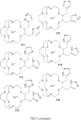
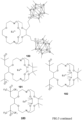
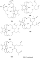
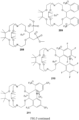
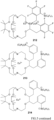
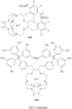
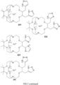
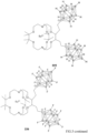
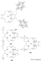
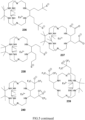
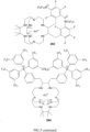
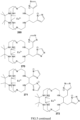
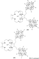
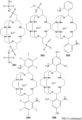
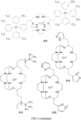
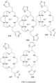
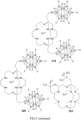
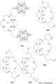
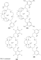
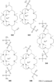
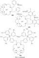
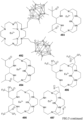
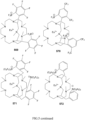
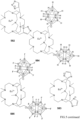
- Preferred examples of the monoanionic groups are shown in Figure 5 .
- the two monoanionic groups are covalently linked with different carbon or nitrogen atoms that are part of the bicyclic or polycyclic ring structure.
- the two monoanionic groups are separated from each other by a sequence of at least two, preferably at least three, more preferably at least four, most preferably at least five intervening atoms.
- the monoanionic groups can compensate the charge of the divalent lanthanide, while the metal-organic coordination compound has a low polarity like quadropole and/or dipole polarity. Consequently, the metal-organic coordination compound has molecular character instead of salt character and has higher miscibility with matrices, can be dissolved in nonpolar solvents and can undergo sublimation or evaporation more easily since intermolecular interactions are reduced.
- the cyclic organic ligand can be freely chosen from monocyclic, bicyclic or polycyclic ligands.
- the number of ring atoms is chosen in a way to allow for the divalent lanthanide to be coordinated inside the cyclic organic ligand.
- the divalent lanthanide is Europium or Ytterbium, most preferably Europium. Therefore, the cyclic organic ligand is preferably selected in a way that the divalent Europium can be contained inside the cyclic structure and does not undergo oxidation.
- the metal-organic coordination compound contains exactly two monoanionic groups covalently linked with a cyclic organic ligand so that the coordination compound is neutrally charged.
- the coordination compound comprises at least one divalent lanthanide coordinated by a cyclic organic ligand having the formula 1-1
- each Y is independently selected from or each Y 1 is independently selected from 3 - to 15-membered, preferably 4- to 12-membered, cyclic organic groups that can contain 1 to 4 hetero atoms selected from N, B, P, O, S and is connected with each Z via a non-neighboring carbon or hetero atom, wherein R 2 is hydrogen or any covalently bound substituent being identical or different in each occurrence.
- each Y2 is independently selected from B, B-R 2 - , N, P, C-R 2 ,
- each Z contains at most one monoanionic group.
- one Z contains two monoanionic groups and the other Z, Y1 and Y2 do not contain monoanionic groups.
- Y1 or Y2 form the monoanionic groups.
- the coordination compound comprises at least one divalent lanthanide coordinated by a cyclic organic ligand according to formula 3-1 wherein
- the compound of formula 3-2 has one or more of the following features:
- the cyclic organic ligand has a structure according to formula 2a, 2c, 2e or 2f: wherein in formula 2a and 2c,
- both anionic groups can be located in the same branch.
- the monoanionic group preferably has the anionic charge in a ⁇ or ⁇ position to the ring carbon or nitrogen atom to which the monoanionic group is covalently bound, or
- the cyclic organic ligand contains exactly two monoanionic groups and therefore is twice negatively charged and with a divalent lanthanide forms a complex of neutral charge.
- the cyclic organic ligand does not contain fluorine atoms or does not contain halogen atoms at all.
- the object is furthermore achieved by a mixture comprising a second electrically neutral organic compound, and the coordination compound as defined above,
- the object is furthermore achieved by a compound comprising the coordination compound as defined above, and a polymer with a molecular weight Mn above 1000 g/mol, wherein the coordination compound is covalently attached to the polymer backbone.
- the objects are furthermore achieved by a contrast enhancement medium for magnet resonance tomography (MRT), the contrast enhancement medium comprising the coordination compound as defined above.
- MRT magnet resonance tomography
- an organic electronic device comprising:
- the organic electronic device is an optoelectronic device, the optoelectronic device being at least one of an organic light-emitting diode, an organic photo detector or a photovoltaic cell.
- the object is furthermore achieved by a method of forming an organic device, the method comprising: Forming a layer of the coordination compound, the mixture or the compound as defined above, wherein the layer is deposited from a gas phase, in particular using an evaporation, carrier gas, and/or sublimation process, and/or by a solution-based process.
- the metal-organic coordination compounds according to the present invention are preferably used in an organic electronic device, more preferably an organic light-emitting device, OLED.
- the monoanionic groups are pointing inwardly in the cyclic organic ligand.
- bulky anions may lead to the formation of blue light-emitting metal-organic coordination compounds, whereas small and hard anions like O- lead to green light-emitting metal-organic coordination compounds.
- Structural isomers can contain the two monoanionic groups at different positions within one branch of a bicyclic or polycyclic organic ligand, or within different branches of a bicyclic or polycyclic ligand.
- Figure 5 shows several examples of structural isomers of this type.
- bicyclic or polycyclic organic ligands are preferred over monocyclic ligands, most preferred are bicyclic ligands.
- substituted phenyl groups are less preferred as anionic groups.
- Various embodiments relate to metal organic compounds, including Yb(II) or Eu(II) coordinated with a macrocyclic organic ligand including a plurality of aliphatic amine groups and the applications of those compounds.
- a coordination compound is taken to mean a compound where the central active metal is coordinated without a direct metal carbon bond.
- an electroluminescent coordination compound is any material that is able to emit light upon electrical excitation, followed by recombination of electrons and holes. It shall be irrelevant in this context, whether the recombination of the electrons and holes takes place directly on the electroluminescent compound or first an excitation is formed on a different compound and subsequently transferred to the electroluminescent compound. Further, the electroluminescent coordination compound does not necessarily have to be used in an electronic device but, as example, may be used as a dye or a contrast enhancement medium for magnet resonance tomography.
- the divalent lanthanide included in the coordination compound may be any lanthanide cation that is twofold positively charged, e.g. Yb2+, Eu2+, and Sm2+, in particular Yb2+ and Eu2+.
- the macrocyclic organic ligand according to various embodiments may be combined with actinides of divalent oxidation state.
- Am2+ has a similar electronic configuration to Eu2+ and may therefore have similarly emission properties.
- the arylene is a divalent organic fragment that is derived from an aromatic or heteroaromatic hydrocarbon by removing two hydrogen atoms from the aromatic or heteroaromatic hydrocarbon, preferably from different carbon and/or hetero atoms.
- an aromatic hydrocarbon or arene is a hydrocarbon with sigma bonds and delocalized pi electrons between carbon atoms forming a circle.
- An alkylene is a divalent organic fragment that is derived from an alkyl group by removing one additional carbon atom.
- halo halogen
- halide halogen
- fluorine chlorine, bromine, and iodine
- acyl refers to a substituted carbonyl radical (C(O)-Rs).
- esters refers to a substituted oxycarbonyl (-O-C(O)-Rs or - C(O)-O-Rs) radical.
- ether refers to an -ORs radical.
- sulfanyl or "thio-ether” are used interchangeably and refer to a -SRs radical.
- sulfinyl refers to a -S(O)-Rs radical.
- sulfonyl refers to a -SO 2 -Rs radical.
- phosphino refers to a -P(R S ) 3 radical, wherein each Rs can be same or different.
- sil refers to a -Si(Rs) 3 radical, wherein each Rs can be same or different.
- Rs can be hydrogen or a substituent selected from the group consisting of deuterium, halogen, alkyl, cycloalkyl, heteroalkyl, heterocycloalkyl, arylalkyl, alkoxy, aryloxy, amino, silyl, alkenyl, cycloalkenyl, heteroalkenyl, alkynyl, aryl, heteroaryl, and combination thereof.
- Preferred Rs are selected from the group consisting of alkyl, cycloalkyl, aryl, heteroaryl, and combination thereof.
- alkyl refers to and includes both straight and branched chain alkyl radicals.
- Preferred alkyl groups are those containing from one to fifteen, preferably one to ten, more preferably one to five carbon atoms and includes methyl, ethyl, propyl, 1-methylethyl, butyl, 1-methylpropyl, 2-methylpropyl, pentyl, 1-methylbutyl, 2-methylbutyl, 3-methylbutyl, 1,1-dimethylpropyl, 1,2-dimethylpropyl, 2,2-dimethylpropyl, and the like. Additionally, the alkyl group is optionally substituted, e.g. by halogen or cycloalkyl.
- cycloalkyl refers to and includes monocyclic, polycyclic, and spiro alkyl radicals.
- Preferred cycloalkyl groups are those containing 3 to 12, preferably 3 to 8, more preferably 3 to 6 ring carbon atoms and includes cyclopropyl, cyclopentyl, cyclohexyl, bicyclo[3.1.1]heptyl, spiro[4.5]decyl, spiro[5.5]undecyl, adamantyl, and the like.
- the cycloalkyl group is optionally substituted, e.g. by halogen, alkyl or heteroalkyl.
- heteroalkyl or “heterocycloalkyl” refer to an alkyl or a cycloalkyl radical, respectively, having at least one carbon atom replaced by a heteroatom.
- the at least one heteroatom is selected from O, S, N, P, B, Si and Se, more preferably O, S or N.
- the radical can be covalently linked with the remainder of the molecule via a carbon or heteroatom (e.g. N).
- the heteroalkyl or heterocycloalkyl group is optionally substituted as indicated for alkyl and cycloalkyl.
- alkenyl refers to and includes both straight and branched chain alkene radicals.
- Alkenyl groups are essentially alkyl groups with more than one carbon atom that include at least one carbon-carbon double bond in the alkyl chain.
- Cycloalkenyl groups are essentially cycloalkyl groups that include at least one carbon-carbon double bond in the cycloalkyl ring.
- heteroalkenyl refers to an alkenyl radical having at least one, preferably 1 to 5, more preferably 1 to 3, most preferably 1 or 2 carbon atoms replaced by a heteroatom.
- the at least one heteroatom is selected from O, S, N, P, B, Si, and Se, more preferably O, S, or N.
- Preferred alkenyl/cycloalkenyl/heteroalkenyl groups are those containing two/three/one to fifteen carbon atoms. Additionally, the alkenyl, cycloalkenyl, or heteroalkenyl group is optionally substituted, as indicated above.
- aralkyl or "arylalkyl” are used interchangeably and refer to an alkyl group that is substituted with an aryl group. Additionally, the aralkyl group is optionally substituted, as indicated for alkyl and aryl.
- heterocyclic group refers to and includes aromatic and non-aromatic cyclic radicals containing at least one, preferably 1 to 5, more preferably 1 to 3, most preferably 1 or 2 heteroatom.
- the at least one heteroatom is selected from O, S, N, P, B, Si, and Se, more preferably O, S, or N.
- Hetero-aromatic cyclic radicals may be used interchangeably with heteroaryl.
- Preferred hetero-non-aromatic cyclic groups are those containing 3 to 7 ring atoms which includes at least one hetero atom, and includes cyclic amines such as morpholino, piperidino, pyrrolidino, and the like, and cyclic ethers/thio-ethers, such as tetrahydrofuran, tetrahydropyran, tetrahydrothiophene, and the like. Further preferred heterocyclic groups are carbazole groups and dibenzofuran groups. Additionally, the heterocyclic group may be optionally substituted, e.g. by halogen, alkyl or aryl. The heterocyclic group can be covalently linked with the remainder of the molecule via carbon and/or heteroatoms, preferably one carbon or nitrogen atom.
- aryl refers to and includes both single-ring aromatic hydrocarbyl groups and polycyclic aromatic ring systems.
- the polycyclic rings may have two or more rings in which two carbons are common to two adjoining rings (the rings are "fused") or wherein one carbon is common to two adjoining rings (e.g. biphenyl) wherein at least one of the rings is an aromatic hydrocarbyl group, e.g., the other rings can be cycloalkyls, cycloalkenyls, aryl, heterocycles, and/or heteroaryls.
- Preferred aryl groups are those containing six to thirty carbon atoms, preferably six to twenty carbon atoms, more preferably six to twelve carbon atoms.
- Suitable aryl groups include phenyl, biphenyl, triphenyl, triphenylene, tetraphenylene, naphthalene, anthracene, phenalene, phenanthrene, fluorene, pyrene, chrysene, perylene, radialene and azulene. Most preferred is phenyl, that can be substituted by non-aromatic groups. Especially preferred is an aryl group having six carbons. Additionally, the aryl group is optionally substituted, e.g. by halogen, alkyl, heteroalkyl.
- heteroaryl refers to and includes both single-ring aromatic groups and polycyclic aromatic ring systems that include at least one heteroatom.
- the heteroatoms include, but are not limited to and are preferably selected from O, S, N, P, B, Si, and Se. In many instances, O, S, or N are the preferred heteroatoms.
- Hetero-single ring aromatic systems are preferably single rings with 5 or 6 ring atoms, and the ring can have from one to five/six, preferably 1 to 3, more preferably 1 or 2 heteroatoms.
- the hetero-polycyclic ring systems can have two or more rings in which two atoms are common to two adjoining rings (the rings are "fused") or wherein one carbon is common to two adjoining rings (e.g. bipyridine) wherein at least one of the rings is a heteroaryl, e.g., the other rings can be cycloalkyls, cycloalkenyls, aryl, heterocycles, and/or heteroaryls.
- the hetero-polycyclic aromatic ring systems can have from 1 to 5, preferably 1 to 3, more preferably 1 or 2 heteroatoms per ring of the polycyclic aromatic ring system.
- Preferred heteroaryl groups are those containing three to thirty carbon atoms, preferably three to twenty carbon atoms, more preferably three to twelve carbon atoms.
- Suitable heteroaryl groups include dibenzothiophene, dibenzofuran, dibenzoselenophene, furan, thiophene, benzofuran, benzothiophene, benzoselenophene, carbazole, indolocarbazole, pyridylindole, pyrrolodipyridine, pyrazole, imidazole, triazole, oxazole, thiazole, oxadiazole, oxatriazole, dioxazole, thiadiazole, pyridine, pyridazine, pyrimidine, pyrazine, triazine, oxazine, oxathiazine, oxadiazine, indole, benzimidazole, indazole, indox
- aryl and heteroaryl groups listed above the groups derived from benzene, furan, dibenzofuran, dibenzoselenophene, carbazole, imidazole, pyridine, pyrazine, pyrimidine, triazine, and the respective aza-analogs of each thereof are of particular interest.
- alkyl, cycloalkyl, heteroalkyl, heterocycloalkyl, alkenyl, cycloalkenyl, heteroalkenyl, alkynyl, aralkyl, heterocyclic group, aryl, and heteroaryl groups or residues, as used herein, are independently unsubstituted, or independently substituted, with one or more (general) substituents, preferably the substituents mentioned above.
- the (general) substituents are selected from the group consisting of deuterium, halogen, alkyl, cycloalkyl, heteroalkyl, heterocycloalkyl, arylalkyl, alkoxy, aryloxy, amino, silyl, alkenyl, cycloalkenyl, heteroalkenyl, alkynyl, aryl, heteroaryl, acyl, carboxylic acid, ether, ester, nitrile, isonitrile, sulfanyl, sulfinyl, sulfonyl, phosphino, and combinations thereof with the number of carbon atoms and heteroatoms as defined above for the respective term.
- one or two substituents can be selected from polymer chains which can be covalently linked with the remainder of the molecule by a suitable organic spacer. Therefore, the cyclic organic ligand can be covalently linked with a polymer chain or a polymer backbone.
- Fig. 2E shows possible substituents.
- the preferred general substituents are selected from the group consisting of deuterium, fluorine, alkyl, cycloalkyl, heteroalkyl, alkoxy, aryloxy, amino, silyl, alkenyl, cycloalkenyl, heteroalkenyl, aryl, heteroaryl, nitrile, isonitrile, sulfanyl, and combinations thereof with the number of carbon atoms and heteroatoms as defined above for the respective term.
- the preferred general substituents are selected from the group consisting of deuterium, fluorine, alkyl, cycloalkyl, alkoxy, aryloxy, amino, silyl, aryl, heteroaryl, sulfanyl, and combinations thereof with the number of carbon atoms and heteroatoms as defined above for the respective term.
- the more preferred general substituents are selected from the group consisting of deuterium, fluorine, alkyl, cycloalkyl, aryl, heteroaryl, and combinations thereof with the number of carbon atoms and heteroatoms as defined above for the respective term.
- substituted and substitution refer to a substituent other than H that is bonded to the relevant position, e.g., a carbon or nitrogen.
- R1 represents mono-substitution
- one R1 must be other than H (i.e., a substitution).
- R1 represents di-substitution, then two of R1 must be other than H.
- R1 represents no substitution
- R1 can be a hydrogen for available valencies of straight or branched chain or ring atoms, as in carbon atoms for benzene and the nitrogen atom in pyrrole, or simply represents nothing for ring atoms with fully filled valencies, e.g., the nitrogen atom in pyridine.
- the maximum number of substitutions possible in a straight or branched chain or ring structure will depend on the total number of available valencies in the ring atoms or number of hydrogen atoms that can be replaced. All residues and substituents are selected in a way that a chemically stable and accessible chemical group results.
- substitution includes a combination of two to four of the listed groups.
- substitution includes a combination of two to three groups.
- substitution includes a combination of two groups.
- Preferred combinations of substituent groups are those that contain up to fifty atoms that are not hydrogen or deuterium, or those which include up to forty atoms that are not hydrogen or deuterium, or those that include up to thirty atoms that are not hydrogen or deuterium counted for all substituents of a given molecule, or for the respective molecule in total. In many instances, a preferred combination of substituent groups will include up to twenty atoms that are not hydrogen or deuterium, counted for all substituents of a given molecule.
- aza designation in the fragments described herein, i.e. aza-cryptate, etc. means that one or more carbon atom or (other) heteroatom of a parent compound is replaced by a nitrogen atom, without any limitation.
- a crown ether -O- is replaced by -NH- to give the respective aza compound.
- One of ordinary skill in the art can readily envision other nitrogen analogs of the aza-derivatives, and all such analogs are intended to be encompassed by the terms as set forth herein.
- deuterium refers to an isotope of hydrogen. Deuterated compounds can be readily prepared using methods known in the art.
- a pair of adjacent or non-adjacent substituents or residues can be optionally joined (i.e. covalently linked with each other) or fused into a ring.
- the preferred ring formed therewith is a five-, six-, or seven-membered carbocyclic or heterocyclic ring, including both instances where the portion of the ring formed by the pair of substituents is saturated and where the portion of the ring formed by the pair of substituents is unsaturated.
- adjacent means that the two substituents involved can be on the same ring next to each other, or on two neighboring rings having the two closest available substitutable positions, such as 2, 2' positions in a biphenyl, or 1, 8 position in a naphthalene, or 2,3-positions in a phenyl, or 1,2-positions in a piperidine, as long as they can form a stable fused ring system.
- the divalent Lanthanide is Europium or Ytterbium.
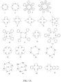
- the coordination compound may contain any organic ligand according to FIG. 1A.
- FIG. 1A illustrates examples 1 to 21 of the organic ligand according to various embodiments without limitation.
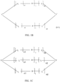
- FIG 1B and 1C illustrate organic ligands according to the present invention.
- the coordination compound may include organic ligands described by the generic formula illustrated in FIG. 2A .
- m preferably is an integer from 1 to 15
- X is independently in each occurrence O or N-R 2
- R 1 and R 2 may be the same or different in each occurrence.
- Specific examples according to FIG. 2A which shall, however, not limit the full scope of the possible set of materials, are compounds 22 to 27 illustrated in FIG. 2B .
- the coordination compounds include cyclic organic ligands which are polycyclic ligands also known as cryptands. Examples are described by generic formula illustrated in FIG. 2C .
- L 1 represents the linker, formed from two R 2 substituents, connected to each other at any position.
- Specific examples according to the formula illustrated in FIG. 2C which shall not limit the scope, are compounds 28 to 42 illustrated in FIG. 2D .
- the coordination compound according to various embodiments may contain a ligand according to formula (1-1), (1-2), (3-1) or (3-2) with a plurality of substituents, which are not equal to hydrogen.
- substituents Preferably 0 to 18, more preferably 0 to 12 or 0 to 6 of these substituents can be present, for example 1 to 18, 1 to 12 or 1 to 6 substituents.
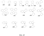
- Those substituents may be any chemical fragment that can be covalently attached in accordance to the formula (1-1), (1-2), (3-1) or (3-2) . Examples of substituents s1 to s80 are illustrated in FIG. 2E , FIG. 2F and FIG. 2G .
- dashed lines may show the preferred covalent attachment to the macrocyclic ligand backbone according to the formula (1-1), (1-2), (3-1) or (3-2).
- the substituents may form any cyclic bridges with each other, and examples, which however shall not limit the scope, are illustrated in FIG. 2F and FIG. 2G .
- a dashed line may represent the connection of the shown molecular fragment to the macrocyclic backbone of formula (1-1), (1-2), (3-1) or (3-2).
- X 2 may be selected from O or N-R 6 and k may be an integer between 4 and 20 and R 3 to R 6 are selected independently in each occurrence from hydrogen, deuterium, in various embodiments substituted C1-C10 linear or branched alkyl, perfluorinated alkyl, partially fluorinated alkyl, in various embodiments substituted aryl, in various embodiments substituted heteroaryl, perfluorinated aryl, partially fluorinated aryl, in various embodiments substituted cycloalkyl, in various embodiments substituted alkenyl, in various embodiments substituted alkynyl.
- the substituents include an anionic group.
- the organic ligand illustrated in FIG. 1A to C may be configured to include two singly charged anions.
- a light emitting chemical cell may be an embodiment of an OLED in this description.
- Drift of charged species within a device including the organic electroluminescent coordination compound according to the formula illustrated in FIG. 1A or B can be avoided according to the present invention.
- a drift in the electrical field of an OLED can be prevented, leading to an improved stability of the OLED device.
- ion drift may lead to time dependent OLED characteristics, which may be difficult to control, and may not be desirable as such.
- the coordination compounds of the present invention do not show this type of ion drift.
- the choice of the covalently linked anions may depend strongly on the application.
- a coordination compound according to various embodiments may exhibit an exceptionally large dipole moment.
- an unwanted polarity quadrupole or dipole
- the emitter material preferably has a molecular instead of salt-like character and can be easily mixed with neutral substantially organic matrices.
- the improved solubility in nonpolar solvent and the better sublimation behavior can be advantageous.
- the cyclic organic ligand has the formula 3-1 or 3-2: wherein
- L for each occurrence independently is a divalent cyclic organic group that can be substitued and that is formed by removing two hydrogen atoms from neighboring carbon and/or nitrogen atoms in the ring.
- n1 and n2 are 1 or 2, more preferably 1, so that the sum of n1+n2 is 2, 3, or 4, more preferably 2 or 3, specifically 2.
- the compound of formula 3-2 has one or more of the following features:
- any number of the above features can be combined to form a preferred subset of compounds of formula 3.
- 2, 3 or 4 of the features can be combined to give a more preferred compound of formula 3, which has to include two monoanionic groups.
- a metal organic coordination compound is provided that is highly stabilized against oxidation such that processing at ambient conditions becomes possible, but at the same time refraining from using soft coordinating ligands such that the beneficial intra-metallic optical transitions of the central metal ion are not shifted into the red spectral region.
- this is achieved by creating a hard, nitrogen-based coordination sphere for the central divalent ion, and simultaneously preventing oxidation using a plurality of bulky aliphatic substitutions.
- the excitation resides substantially on a single atom, giving rise to an atomic excited state.
- the single atom is sufficiently heavy such that both, spin 0 and spin 1 excitations contribute to light emission by means of the heavy metal effect.
- the coordination compound includes Eu 2+ or Yb 2+ and cyclic organic ligands that coordinate to Eu 2+ or Yb 2+ .
- Ytterbium or Europium in oxidation state +2 preferably are coordinated by an organic ligand represented by the formula illustrated in FIG. 3 .
- FIG. 3 illustrates, preferably in formula 2a, an embodiment of the cyclic organic ligand illustrated in FIG. 1A-FIG. 2K according to the present invention.
- the cyclic organic ligand of formula 1 has a structure according to formula 2a, 2c, 2e or 2f, as shown in FIG. 3 : wherein
- the monoanionic group has the anionic charge in a ⁇ - or ⁇ -position to the ring carbon or nitrogen atom to which the monoanionic group is covalently bound, or wherein in formula 2a and 2c,
- R 1 , R 2 , R 3 , R 4 , R 5 , R 6 in formula 2a independently in each occurrence represent an organyl group, comprising at least one carbon atom, preferably at least one additional atom different from hydrogen, more preferably at least two carbon atoms
- R 1 , R 2 , R 3 , R 4 , R 5 , R 6 , R 7 in formula 2b, 2c, 2d, 2e, 2f independently in each occurrence represent hydrogen or an organyl group, comprising at least one carbon atom
- R 1 , R 2 , R 3 , R 4 , R 5 , R 6 independently in each occurrence can represent an organoheteryl group.
- a, b, c are each independently an integer of 0 or more.
- a, b and c are each equal to 1.
- the term (electroluminescent) coordination compound may be describing molecules, including metal cations that may be bound to a charged ligand represented by the formula illustrated in FIG. 3 .
- organoheteryl group as used herein defines an univalent group including one or more carbon atoms and one or more heteroatoms, which will be thus organic, but which has its free valence at an atom other than carbon.
- FIG. 4C illustrates the examples of organoheteryl groups f68 to f78, wherein a dashed line may represent preferred connection points.
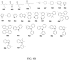
- FIG. 4A to FIG. 4C illustrate chemical formulas of R 1 , R 2 , R 3 , R 4 , R 5 , R 6 of the cyclic organic ligand illustrated in FIG. 3 , preferably formula 2a.
- R 1 , R 2 , R 3 , R 4 , R 5 , R 6 may be in each occurrence independently selected from the group of f1 to f78.
- organyl group as used herein defines an organic substituent group, regardless of functional type and constitution, having one free valence at a carbon atom and thus containing at least one carbon atom. Preferably, it contains at least one additional atom, which is different from hydrogen.
- the organyl group preferably includes one to 25 carbon atoms, more preferably the organyl group includes 2 to 25 carbon atoms, more preferably the organyl group includes 3 to 25 carbon atoms.
- FIG. 4A and FIG. 4B illustrate examples of organyl group f1 to f67, wherein a dashed line may represent preferred connection points.
- the value of a, b, c in the formula illustrated in FIG. 3 is preferably an integer of from 0 to 5, preferably 0 to 3, more preferably 0 to 1.
- the organyl or organoheteryl group includes a charged group, providing a negative monoanionic charge to the ligand. Examples of charged groups are presented in FIG. 4D .
- a dashed line represents preferred connection points.
- R 7 , R 8 , R 10 , R 11 , R 12 , R 13 , R 14 represent divalent groups formed by removing two hydrogen atoms from (preferably substituted) alkanes, or (preferably substituted) arenes or (preferably substituted) heteroarenes and the free valencies of which are not engaged in a double bond.
- the coordination compound comprises two monoanionic groups, which are covalently bound to the organic ligand, wherein the negatively charged anion is at least one selected from the group of g1 to g7 and f79 to f85, wherein g1 to g7 and f79 to f85 are wherein
- substituted means that a hydrogen atom, attached to the parent structure is replaced by a non-hydrogen atom or by a group of atoms forming a chemical group.
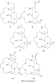
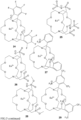
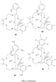
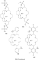
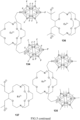
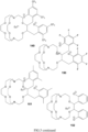
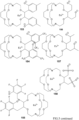
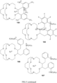
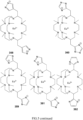
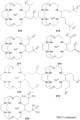
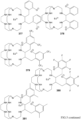
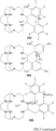
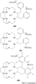
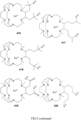
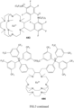
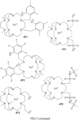
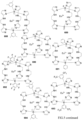
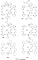
- Fig 5 shows several metal-organic coordination compounds according to the present invention.
- the compounds are exemplary for the concept of the present invention wherein two monoanionic groups are covalently linked with a cyclic organic ligand.
- the compounds shown have a polycyclic group to which the two monoanionic groups are covalently linked.
- the monoanionic groups can be freely exchanged between the different bicyclic or polycyclic structures.
- the cyclic organic ligand can contain further substituents, specifically organyl groups, organoheteryl groups, aryl groups, heteroaryl groups, heterocyclic groups, alkenyl groups, heteroalkyl groups, hetero cycloalkyl groups, cycloalkyl groups, alkyl groups or combinations thereof.
- halogen substituents may be present in the different compounds.
- the cyclic organic ligand is a bicyclic or polycyclic organic ligand.
- This bicyclic or polycyclic organic ligand is preferably selected from the bicyclic or polycyclic groups shown in structures 4, 112, 230, 327, 477, 509, 549, 624, 647, 654, 660, 672, 678, 684, 690, 702, 708, 714, 756, 762.
- one or more substituents can be added or removed.
- covalently linked monoanionic groups can be exchanged by other monoanionic groups.
- the position at which the monoanionic groups are linked with the bicyclic or polycyclic structure can be changed. Therefore, the bicyclic or polycyclic organic core is preferred with being bound to the specific compound depicted.
- the hydrogens shown can be replaced by substituents.
- one or more hydrogen atoms of the carbocyclic groups can be exchanged by substituents.
- the position at which the two monoanionic groups are covalently linked can be changed within the cyclic residue.
- substituents may replace the shown hydrogen atoms or hydrogen atoms attached to carbon atoms.
- the monoanionic groups can be freely chosen from all possible covalently linked monoanionic groups, for example as shown in structures 510, 511 ff.
- the above-listed structures are exemplary for the core bicyclic or polycyclic structure, to which the two monoanionic groups are covalently linked, and not limited to the specific compound shown.
- the two substituents on the left hand side bearing the monoanionic groups can be positioned in different locations of the cyclic structure and can be replaced by other monoanionic groups. Further substituents can be present.
- structure 230 shows methyl substituents on ring carbon atoms. These methyl substituents can be replaced by hydrogen or other substituents, and the two shown monoanionic groups can be attached to different positions of the cyclic organic ligand.
- the present invention will encompass any possible combination of bicyclic or polycyclic ring structures, monoanionic groups and substituents shown in Figure 5 .
- the coordination components according to the present invention only contain the bicyclic or polycyclic structure shown in any of the formulae in combination with the monoanionic groups shown in any of the formulae, specifically the bicyclic or polycyclic structures 4, 112, 230, 327, 477, 509, 549, 624, 647, 654, 660, 672, 678, 684, 690, 702, 708, 714, 756, 762.
- the monoanionic group is part of the ring structures as for example in structure 654, the location of these monoanionic groups cannot be changed, and there cannot be any additional monoanionic groups.
- the bicyclic or polycyclic group or core of the cyclic organic ligand is selected from one of those shown in Figure 5 and specifically the above-mentioned structures 4, 112, 230, 327, 477, 509, 549, 624, 647, 654, 660, 672, 678, 684, 690, 702, 708, 714, 756, 762.
- This bicyclic or polycyclic group or core can be substituted and bears the two monoanionic groups.
- the monoanionic groups covalently linked with a cyclic organic ligand are preferably chosen from those shown in the structures of Figure 5 , more preferably those of the above-mentioned structures 4, 112, 230, 327, 477, 509, 549, 624, 647, 654, 660, 672, 678, 684, 690, 702, 708, 714, 756, 762.
- the dashed line shows the position in which the monoanionic groups are covalently linked with a cyclic organic ligand.
- the dashed line can be a single bond or a spacer group, for example a C1-12-alkylene spacer group, more preferably C1-6-alkylene spacer group.
- the cyclic organic ligand and the shown monoanionic groups can be separated by a covalent bond or 1, 2, 3, 4, 5 or 6 carbon atoms in a preferred embodiment.
- covalently linked monoanionic groups can for example be linked with the cyclic groups shown in Figures 1A , 1B , 1C , 2A , 2B , 2C, 2D , the core structures or preferred core structures shown in Figure 5 and specifically in above-mentioned structures 4, 112, 230, 327, 477, 509, 549, 624, 647, 654, 660, 672, 678, 684, 690, 702, 708, 714, 756, 762 as outlined above, the structure shown in Figure 6A an 6B, 11 and 15.
- any covalently linked monoanionic group can be present in the following structures.
- the position of the two monoanionic groups can be freely chosen between the shown substituents.
- preferably 0 to 16 of the shown groups represent substituents and thus are different from hydrogen.
- the last two cyclic organic ligands have monoanionic charge at the boron atoms. Therefore, no additional monoanionic group is present.
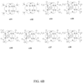
- the cyclic organic ligand may be selected from the group of c15 to c44 illustrated in FIG. 6A and FIG. 6B , while the two monoanionic groups are covalently linked with the shown cyclic organic ligands.
- the coordination compound according to the invention may be used in a mixture with at least one second electrically neutral or charged organic compound.
- the second organic compound may have a triplet energy higher than 2.5 eV,more preferably higher than 2.6 eV and even more preferably higher than 2.7 eV to ensure that the excitation is confined at the preferably blue light emitting coordination compound according to the invention.
- the coordination compound may have a higher hole affinity compared to the second organic compound.
- a compound may include the coordination compound according to any of the described or illustrated embodiments and a polymer with a molecular weight Mn above 1000 g/mol.
- the coordination compound may be covalently attached to the polymer backbone.
- the polymer molecule may be an auxiliary organic molecule.
- any of the side groups R 1 , R 2 of the formula (3-1) or (3-2) may be linked to another organic molecule, such as a polymer.
- Some repeat units of polymers that may bind to the coordination compound of formula (3-1) or (3-2) via R 1 or R 2 are illustrated in FIG. 7A as p1 to p5.
- a dashed line may represent a preferred connection to R 1 or R 2 . It is, however, understood that those are specific examples for illustration purpose only.
- a contrast enhancement medium for magnet resonance tomography may include the coordination compound according to the invention e.g. as a pure compound, in a mixture or a compound as described before.
- MRT magnet resonance tomography
- the coordination compound according to various embodiments may be dispersed into a matrix of suitable optical properties, such as for example a high transparency in certain desired parts of the visible spectrum. If this matrix is brought in optical contact to a light source emitting at sufficiently short wavelength, this light may be absorbed by the coordination compound and reemitted at substantially longer wavelength.
- a suitable light source may for example be a light emitting diode emitting light at wavelength substantially shorter than 430 nm, which may be reemitted by the coordination compound at wavelength longer than 430 nm.
- the matrix may have any physical dimensions. It may for example be a thin layer of 10 nm to 10,000 nm.
- the matrix may as well be of granular form or in form of small particles of average diameter between 10 nm and 100,000 nm. For use in optical devices, in the latter cases, the matrix may be applied inside another host material for support.
- an organic electronic device may be any device or structure including substantially organic layers or subunits, where an electro-magnetic stimulus may be converted into an electrical field or current or vice versa, or where an input electrical current or electrical field may be used to modulate an output electrical current or electrical field.
- the organic electronic device including the coordination compound according to various embodiments may be used as semiconducting organic material in an organic field-effect transistor or an organic thin-film transistor.
- the organic electronic device converts external static or dynamic magnetic fields into proportional, measurable electrical signals and thus becomes a magnet field sensor.
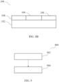
- FIG. 8A and FIG. 8B illustrate embodiments of an organic electronic device 100 configured as optically active device.
- the organic electronic device may include a first electrode 104, e.g. on a substrate 102 or as the substrate; a second electrode 108; and an organic layer 106 arranged such that it is electrically interposed between the first and second electrodes 104, 108.
- the first and second electrodes 104, 108 may be electrically insulated from each other by an insulating structure 110, e.g. a resin or polyimide.
- the first and second electrodes 104, 108 may be stacked over each other ( FIG. 8A ) or may be arranged in a common plane ( FIG. 8B ).
- the organic layer 106 may include the coordination compound according to any of the described or illustrated embodiments, e.g. as a pure compound, in a mixture or in a compound as described before.
- the organic electronic device 100 may be an optoelectronic device, the optoelectronic device being at least one of an organic light emitting diode (OLED), an organic photodetector, or a photovoltaic cell. That is, photons from an external electromagnetic field may be absorbed in the organic layer 106 and converted into current by means of an electrical field between the first and second electrodes 104, 108.
- OLED organic light emitting diode
- OCV organic photovoltaic
- the paramagnetic moments of the coordination compounds including divalent Europium may be aligned to exhibit a macroscopic magnetic moment.
- This macroscopic moment of the organic layer 106 may be employed as part of a magneto-optic or magneto-electric sensor. It may as well be used as part of a touchscreen function of a flat panel display. It may as well be used to build spintronic devices.
- the alignment of the paramagnetic coordination compound according to various embodiments may be achieved with any suitable technique, for example, but not limited to, techniques that align the coordination compound during, or after processing.
- the coordination compound may be aligned after processing using a strong external electro-magnetic, or static magnetic field.
- the alignment may be improved or permanently frozen-in by heating the organic layer 106 to be aligned.
- the heating may proceed above the glass-transition temperature or beyond the melting temperature of the coordination compound or parts or the whole organic layer 106.
- the paramagnetic coordination compound may be aligned in-situ during processing of the layer including the paramagnetic coordination compound, for example, but not limited to, by application of a static or dynamic external magnetic field during the processing from either solution or gas phase.
- the macroscopic magnetic moment may as well be formed inhomogeneously over the area of the device by applying suitable external magnetic sources during processing.
- the organic layer 106 is arranged electrically between the first and second electrodes 104, 108 such that an electronic current may flow from the first electrode 104 through the organic layer 106 to the second electrode 108 and vice versa during operation, e.g. in light emission applications.
- a charge carrier pair may be formed in the organic layer 106 and charge carriers of the charge carrier pair may be transported to the first and second electrodes 104, 108 respectively.
- holes and electrons are injected from the anode and the cathode, respectively, and drift towards the organic layer 106, where charges of opposite sign recombine to form a short-lived localized excited state.
- the short-lived excited state may relax to the ground state thereby giving rise to light emission.
- the first and second electrodes 104, 108 may be substantially unstructured layers, e.g. for general lighting applications, or may be structured, e.g. for light emitting diodes or transistors for pixels in a display application.
- the organic electronic device 100 may be configured to emit substantially monochromatic light such as red, green, blue, or polychromatic light such as white.
- the light may be emitted through the first electrode 104 (bottom emitter), through the second electrode 108 (top emitter), or through first and second electrodes 104, 108 (bidirectional emitter).
- the light may as well substantially be emitted in a direction parallel to the organic layer 106 using suitable opaque electrodes 104, 108.
- the device may be an organic laser, which, in this description, may be considered as a specific type of electroluminescent devices.
- the coordination compounds according to various embodiments may have excellent emission properties, including a narrow, deep blue emission spectrum with short excited state lifetime.
- an electroluminescent device may be any device including an organic layer disposed between and electrically connected to an anode 104/108 and a cathode 108/104.
- holes and electrons may be injected from the anode 104/108 and the cathode 108/104, respectively, and drift towards the organic layer 106, where charges of opposite sign recombine to form a short-lived localized excited state.
- the short-lived excited state may relax to the ground state thereby giving rise to light emission. Relaxation pathways without light emission, such as thermal relaxation, may be possible too, but may be considered undesirable, as they lower the conversion efficiency of current into light of the device.
- Further layers may be formed and in electrical connection between the first and second electrodes 104, 108, e.g. configured for charge carrier (electron or hole) injection, configured for charge carrier transport, configured for charge carrier blockage or configured for charge generation.
- the recombination of electrons and holes may as well happen at the interface of the organic layer 106, which contains the coordination compound according to the invention and an adjacent layer, such an electron blocking layer.
- Further optically functional layers e.g. a further electroluminescent material and/or a wavelength conversion material may be formed electrically between the first and second electrodes 104, 108 and in the optical path of the organic layer 106, e.g. on top of the second electrode 108 and/or on the opposite side of the substrate 102.
- encapsulation structures may be formed encapsulating the electrically active area, e.g. the area in which an electrical current flows, and may be configured to reduce or avoid an intrusion of oxygen and/or water into the electrically active area.
- Further optically functional layers e.g. an antireflection coating, a waveguide structure and/or an optical decoupling layer may be formed within the optical light path of the organic layer 106.
- hole or electron blocking layers may be used to optimize the individual hole and electron currents through the organic electronic device 100. This may be known to those skilled in the art as charge balance in order to optimize efficiency and operational stability.
- dedicated hole or electron charge transport layers may be present in the organic electronic device 100 to space the emission region from the first and second electrodes 104, 108.
- Examples of hole transport materials include known materials such as fluorene and derivatives thereof, aromatic amine and derivatives thereof, carbazole derivatives, and polyparaphenylene derivatives.
- Examples of electron transport materials include oxadiazole derivatives, triazine derivatives, anthraquinodimethane and derivatives thereof, benzoquinone and derivatives thereof, naphthoquinone and derivatives thereof, anthraquinone and derivatives thereof, tetracyanoanthraquinodimethane and derivatives thereof, fluorenone derivatives, diphenyldicyanoethylene and its derivative, diphenoquinone derivatives, and metal complexes of 8-hydroxyquinoline and its derivatives and various derivatives of silanes.
- those charge transport layers may include electrical dopant molecules or metals, or may be in contact to charge injection layers. Any of those auxiliary layers may be fully organic or may include inorganic functional moieties.
- charge transport layers may be made of the class of Perovskite materials.
- the coordination compound as illustrated or described in any one of the embodiments may be used as a pure organic emitting layer 106 of any thickness in the range of 0.1 nm and 100 nm, preferably in the range of 0.1 and 10 nm.
- the organic layer 106 may in various embodiments include charge transport materials to improve charge transport into and through the organic layer 106.
- Charge transport materials may be any material that is able to transport either holes or electrons or both types of charges.
- a charge transport material may be any aryl, or heteroaryl organic compound or any metal complex or any mixture thereof.
- Examples of materials present in the light emitting layer 106 include carbazole derivatives, including carbazole-phophine oxide materials, oxadiazole derivatives, triazine derivatives, silane derivatives and any other material or combination of materials with sufficiently high triplet level that may transport charges or otherwise benefit the device performance.
- the volume percentage of the coordination compound as a function of the combined charge transport materials may be between 0.5 and 99.5 vol% in the organic layer 106.
- the oxidation potential of the coordination compound of the organic layer 106 may be higher compared to all charge transport materials present in the organic layer 106.
- a wide variety of techniques on how to measure oxidation potentials have been published in the literature. However, for the purpose of various embodiments, the particular technique of how to measure the oxidation potential is not essential, e.g. only the relative order between the coordination compound and the charge transport materials may be of importance. Oxidation potentials may for example be deducted using quantum mechanical computing techniques based on density functional theory and experimental techniques are very well known in the art, e.g. see R.J.Cox, Photographic Sensitivity, Academic Press, 1973, Chapter 15 .
- the organic layer 106 may contain any other organic or inorganic material in a range of 0.1 to 99.9 vol% that are not intended to transport charges.
- the organic layer 106 may include polymers (in a mixture or as a compound) may be added to improve film quality and prevent crystallization. Other materials may be added to evenly space the coordination compound inside the organic layer 106.
- the divalent lanthanides may allow the ease of processing using vacuum based techniques.
- organic electronic devices such as organic photovoltaic (OPV), organic light emitting diodes (OLED), organic sensors, organic memory or organic sensors
- OCV organic photovoltaic
- OLED organic light emitting diodes
- the evaporation temperature of the compounds including the divalent lanthanides may be sufficiently low to allow for thermal vacuum processing techniques to be used.
- Reduced evaporation temperatures can be achieved according to the invention by using the metal-organic coordination compounds as here the ionic character of the compounds is strongly suppressed, if compared to a similar organic salts without covalently attached monoanionic groups. Consequently, the evaporation temperature is reduced and incorporation into organic electronic devices becomes possible using state-of-the-art vacuum deposition techniques.
- the excitation of the light emitting coordination compound may be energetically confined. This way, high efficiencies may be achieved.
- confinement layers may be formed adjacent to the organic layer 106, wherein the confinement layers may have a triplet energy T 1 higher than 1.8 eV, e.g. higher than 2.3eV, e.g. higher than 2.7 eV.
- any material of the organic layer 106 (other than the electroluminescent compound) may have a triplet energy T 1 higher than 1.8 eV, e.g. higher than 2.3eV, e.g. higher than 2.7 eV.
- the organic electronic device 100 includes two or more sub units each including at least one light emitting layer.
- the subunits may be stacked over each other physically separated and electrically connected by a charge generation layer or, alternatively, may be arranged side by side.
- the subunits may be subpixels of a pixel in a display or general lighting application.
- the light emitted by the subunits may be mixed to generate a light of a predetermined color.
- Each subunit may emit light of the same or a different color.
- the overall light emitted by such organic electronic device 100 may contain a narrow spectral region, such as blue, or may contain a wide spectral region such as white, or a combination thereof.
- the coordination compound illustrated or described in any one of the embodiments may or may not be present in all subunits of the organic electronic device 100.
- the light emitted by the organic electronic device 100 may be in optical contact to at least one optically active layer, including any optically active materials such as organic molecules or quantum dots.
- the optically active layer may be a spectral filter element, which may absorb part of the light emitted by the organic electronic device 100.
- the optically active layer may absorb at least part of the light emitted by the organic electronic device 100 and may reemit it at longer wavelength (wavelength conversion).
- the organic layer 106 may be configured to emit light substantially at wavelengths shorter than 500 nm and the optically active layer may be configured to substantially reemit light at wavelengths longer than 500 nm.
- the optically active layer may be placed in between the anode and cathode of the organic electronic device 100 or outside of it.
- the optically active layer may as well be part of the organic layer 106.
- the organic electronic device 100 may be configured as a large area OLED device used for illumination, signage, or as a backlight.
- the organic electronic device 100 may include a plurality of OLEDs arranged in a pixilated layout (plurality of OLED pixels) that are individually connected electrically, e.g. for flat panel display applications.
- individual pixels may have the capability of emitting light of substantially narrow spectral portions; especially of red, green, and blue.
- the coordination compound may or may not be present in any of the individual pixels.
- the individual pixels may be configured to emit white light. Red, green, and blue spectral portions are generated by using suitable filter elements in optical contact with the pixelated OLEDs.
- the OLED pixels emit blue light and the red and green spectral portions may be generated by using a suitable color conversion element in optical contact with the OLED pixels.
- the organic electronic device 100 includes an anode 104; a cathode 108; and an organic layer 106 disposed between the anode 104 and the cathode 108.
- the organic layer 106 includes an electroluminescent coordination compound according to various embodiments.
- the coordination compound includes at least one divalent lanthanide coordinated by a cyclic organic ligand according to the present invention.
- the divalent Lanthanide may be Europium or Ytterbium.
- the organic ligand according to the invention is electrically neutral.
- the coordination compound includes two monoanionic groups in covalently linked form.
- the coordination compound may be imbedded into at least one second electrically neutral organic compound.
- the second organic compound may have a triplet energy higher than 2.5eV, more preferably higher than 2.6eV and even more preferably higher than 2.7eV.
- the coordination compound may have a higher hole affinity compared to the second organic compound.
- An organic electronic device 100 may be fabricated using a wide range of commonly used techniques, including, but not limited to, deposition of all or some layer, from gas phase vacuum deposition, solution phase, or gas phase using a carrier gas method.
- deposition via the gas phase in vacuum may be used, whereby the coordination compound may either undergo sublimation or evaporation.
- the coordination compounds according to the invention show an improved sublimation/evaporation yield.
- the transfer into the gas phase may be improved by using a carrier gas technology, whereby an inert gas that may not be deposited into the organic layer may be helping the sublimation or evaporation of the coordination compound to be deposited.
- the coordination compound may as well be co-deposited with one or more material to fabricate any desired mixed layers.
- FIG. 9 illustrates a flow diagram of a method of forming an organic device
- the method may include forming 900 of a layer of the coordination compound according to any of the described or illustrated embodiments as a pure compound or in a mixture or linked to a polymer as described before.
- the layer may be deposited from a gas phase, in particular using an evaporation and/or sublimation process, and/or by a solution-based process.
- the forming 900 of the layer may include forming 902 a first layer including the organic ligand and forming 904 a second layer directly in contact with the first layer, wherein the second layer includes a divalent lanthanide salt.
- the second layer may be deposited by a solution-based or thermal vacuum based process.
- the coordination compound according to various embodiments may be formed in-situ using gas phase deposition techniques.
- the organic ligand of the invention according to the formula illustrated in FIG. 1B or C but excluding the divalent lanthanide metal, may be first (902) deposited onto a suitable substrate or other organic layer thereby forming a seed layer. Any suitable technique may be used to fabricate this seed layer.
- This seed layer including the organic ligand may include any other material; preferred may be organic charge transport materials, for example, suitable to achieve hole transport. Preferred may be in various embodiments inert organic or inorganic materials that aid the layer formation, improve its thermal stability, or improve the distribution of the organic ligand within this seed layer.
- a molecular salt including a divalent lanthanide may be evaporated.
- the divalent lanthanide salt may be any charge neutral compound including a lanthanide in its divalent oxidation state and one or two suitable anions.
- the divalent lanthanide salt may as well be simultaneously co-deposited with one or more material to fabricate mixed layers.
- the divalent lanthanide salt may interact with the organic ligand to form the coordination compound according to various embodiments in-situ.
- the lanthanide salt may be processed first and the ligand according to FIG. 1B or C is processed in a second step.
- a lanthanide metal vapor may be used to form the coordination compound according to various embodiments in-situ. In the latter case, an oxidation of the lanthanide takes place. This reaction may be improved by the presence of suitable electron acceptor units in the seed layer or by using the neutral acid version of the ligand illustrated in FIG. 1B or C . Suitable electron acceptors present in the seed layer may be the reduced, i.e. charge neutral p-dopants.
- the metal-organic coordination compound is using gas phase deposition techniques. In this way, there is no need to employ divalent lanthanide salts in which the anions have to be removed afterwards. Since the metal-organic coordination compounds according to the present invention contain the two monoanionic groups covalently linked with a cyclic organic ligand, both the divalent lanthanide and the cyclic organic ligand can be gas phase deposited at the same time.
- Another preferred technique to fabricate layers including the coordination compound according to various embodiments may be deposition from a liquid phase using a mixture or a single organic solvent, whereby the coordination compound according to various embodiments may be dissolved or forms a suspension within the organic solvent; in this description may be referred to as the ink.
- the ink using this deposition process may include a wide variety of other materials apart from the coordination compound according to various embodiments to allow fabrication of mixed layers from solution.
- Additives within the ink may for example, but may not be limited to, be organic or inorganic materials capable of transporting charges, materials that improve the film formation, materials that improve the distribution of the coordination compound within a host material, organic or inorganic materials that improve the efficiency of the device, e.g. by reducing the refractive index.
- the deposition from solution may not be limited to any specific technique.
- Examples of the deposition from solution include spin coating, casting, dip coating, gravure coating, bar coating, roll coating, spray coating, screen printing, flexographic printing, offset printing, inkjet printing.
- the improved solubility of the coordination compounds according to the present invention in non-polar solvents eases the deposition from solution and makes it advantageous.
- organic electronic device Various post processing techniques may be applied to improve the performance or stability of the organic electronic device.
- some or all layers of the organic electronic device include functional groups capable of chemically crosslinking upon thermal or optical exposure thereby forming larger covalently bound molecules with improved physical properties.
- the coordination compounds according to various embodiments exhibit a high paramagnetic moment, e.g. in case the divalent lanthanide is Europium.
- the paramagnetic moments of the coordination compound according to various embodiments may be aligned to exhibit a macroscopic magnetic moment.
- This macroscopic moment of the (organic) layer (106) may be employed as part of a magneto-optic or magneto-electric sensor integrated into the organic electronic device of the invention. It may as well be used as part of a touchscreen function of an organic electronic device flat panel display. It may as well be used to build opto-electronic light emitting spintronic devices.
- the alignment of the paramagnetic coordination compound may be achieved with any suitable technique, for example, but not limited to, techniques that align the coordination compound during, or after processing.
- the coordination compound may be aligned after processing using a strong external electro-magnetic, or static magnetic field.
- the alignment may be improved or permanently frozen-in by heating the organic layer to be aligned.
- the heating may proceed above the glass-transition temperature or beyond the melting temperature of the coordination compound or parts or the whole organic layer (106).
- the paramagnetic coordination compound may be aligned in-situ during processing of the layer including the paramagnetic coordination compound, for example, but not limited to, by application of a static or dynamic external magnetic field during the processing from either solution or gas phase.
- the macroscopic magnetic moment may as well be formed inhomogeneously over the area of the organic electronic device by applying suitable external magnetic sources during processing.
- an unwanted polarity (quadrupole and/or dipole) can be reduced, which makes the compounds specifically suitable for OLED applications as they better blend into the organic environment of the OLED device.
- FIG. 10 illustrates a flow diagram of a method to synthesize the coordination compound according to any of the described or illustrated embodiments.
- the method 1000 may include a reaction of a divalent lanthanide salt and an organic ligand according to any one of FIG. 1 to FIG. 4 at pressure greater than or equal to about 1 bar.
- the method 1000 may include that the divalent lanthanide salt is coordinated with an organic precursor 1002 and subsequently at least one of the groups R1, R2, R3, R4, R5, R6 is attached to the organic precursor 1004.
- the coordination compound may be formed in-situ using deposition from solution.
- the organic ligand of the present invention including or excluding the lanthanide metal may be first deposited onto a suitable substrate or other organic layer thereby forming a seed layer. Any suitable technique may be used to fabricate this seed layer.
- This seed layer including the organic ligand may include any other material.
- Preferred may be organic charge transport materials, for example suitable to achieve hole transport for organic electronic devices.
- Preferred may be further additional inert organic or inorganic materials that aid the layer formation or improve its thermal stability or improve the distribution of the organic ligand within this seed layer.
- a layer including a molecular salt including a divalent lanthanide may be fabricated using a solution process.
- the divalent lanthanide salt may be any charge neutral compound including a lanthanide in an oxidation state 2+ and one or two suitable anions.
- the anions may as well be covalently bound to a suitable polymer.
- the ink including the divalent lanthanide salt may as well include one or more additive to fabricate mixed layers. These additives may be organic or inorganic materials to aid charge transport, may be organic or inorganic materials that improve the efficiency of the device, or may be any material that improves the film formation.
- the solubilized divalent lanthanide metal will interact with the organic ligand to form the coordination compound according to various embodiments in-situ.
- first forming the layer containing the ligand and secondly processing the lanthanide salt may be inverted.
- the metal-organic coordination compound is used directly.
- the method of forming an organic electronic device includes forming an anode; forming a cathode; and forming an organic layer disposed between the anode and the cathode.
- the organic layer may be formed to include an electroluminescent coordination compound.
- the coordination compound may include at least one divalent lanthanide coordinated by a cyclic organic ligand according to the invention
- substituents larger than -CH3 group may be attached to the nitrogen atoms of an azo-cryptand. This way, a needed chemical stability to Eu2+ and Yb2+ coordination compounds is provided.
- the application of such coordination compounds may be useful for an improvement of a luminescence efficiency and a lifetime of the electroluminescent device.
- the organic ligand according to the invention may be synthesized first.
- a suitable salt including the divalent Europium or Ytterbium may be added.
- the coordination compound according to various embodiments may be formed and may precipitate. If bulky ligands are present in the compounds, the coordination compounds according to various embodiments may exhibit a very high kinetic barrier against reaction of the metal cation with the environment.
- Preferred may be ligands according to the formula illustrated in FIG. 11 .
- a, b and c may be independently an integer of 0 or more.
- the monoanionic ligands are not shown.
- the synthesis of coordination compound could be done according to the schema illustrated in FIG. 12 .
- Me may be Eu 2+ or Yb 2+ and a dashed line may represent the coordination bond of the ligand to the central metal ion; a, b, c may be integer of 0 or more, X - may represent the single charged anion, R-Y may represent the compound, which may be able to react with secondary amines.
- the (electroluminescent) coordination compound according to various embodiments may thus be extremely stable and as such ideally suited for a large variety of processing methods and applications.
- At least one of the components set forth in one or more of the preceding figures may be configured to perform one or more operations, techniques, processes, and/or methods as set forth in the example section below.
- a clean and dry 250ml 3-necked round bottom flask, equipped with a magnetic stir bar, reflux condenser fitted with a nitrogen inlet and thermometer may be charged with L1 (7.41, 20mmol).
- the flask may be sealed with a septum, an atmosphere may be replaced by nitrogen.
- Anhydrous trimethylamine (132mmol, 6.6eq, 13.3g) may be added through a septum with a syringe, followed by an addition of anhydrous dichloromethane (100ml) via double tipped cannula.
- the septum may be replaced by an addition funnel, which was charged with a solution of chlorotrimethylsilane (CTMS) (132mmol, 6.6eq., 14.3g), dissolved in 50 ml of anhydrous dichloromethane.
- CTMS chlorotrimethylsilane
- the reaction mixture may be cooled down to -10 °C and the solution of CTMS was added dropwise with a rate, which allows to keep the temperature of the reaction mixture below 0 °C.
- the cooling bath may be removed and the mixture may be stirred at room temperature (3 h) and under reflux (6h) in order to complete the reaction.
- the mixture was cooled using ice bath and quenched by addition of water.
- the septum was replaced by an addition funnel, which was charged with a solution of trifluoroacetic anhydride (66mmol, 6.6eq., 13.88g), dissolved in 25 ml of anhydrous dichloromethane.
- the reaction mixture was cooled down to -10 °C and the solution of anhydride was added dropwise with a rate, which allows to keep the temperature of the reaction mixture below 0 °C.
- the cooling bath was removed and the mixture stirred at room temperature (3 h) in order to complete the reaction.
- the mixture was cooled using ice bath and quenched by addition of water.
- the starting compound, containing secondary amine groups, 13.8mmol (1eq) was treated with 746 mmol (54 eq.) of formaldehyde (37% aqueous solution) and 1.81 mol (55 eq.) of formic acid under reflux for 64 h.
- the reaction was cooled to room temperature and neutralized by an addition of solid NaHCO3 (60-70eq.).
- the mixture was diluted with MeOH and the remaining solid was removed by filtration, a filter cake is washed with methanol.
- Combined filtrate was concentrated, the solid residue extracted with 300 ml propan-2-ol.
- the extract was again concentrated and the residue extracted with 300 ml dichloromethane.
- the liquid phase was concentrated in vacuum to give a yellow oil, which was purified by column chromatography to give a mixture of the three product isomers.
- Octaamine (5,4 mmol, 1,0 eq.) was placed into a reactor, melted and degassed in vacuum at 150° C. The reactor was filled with N2 gas. The amine was cooled down to RT and 15 ml of oxygen-free anhydrous acetonitrile was added to dissolve the solid. A solution of oxirane (10,8 mmol, 2.0 eq.) in 5 ml of oxygen-free anhydrous acetonitrile was dropwise added, followed by an optional addition of lithium tetrafluoroborate (10,79 mmol, 2 eq.) in 10 ml anhydrous oxygen-free acetonitrile. The mixture was stirred for 5 days under reflux, then evaporated to dryness. The solid residue was extracted with toluene, extracts were combined and filtered. Evaporation of the solvent under reduced pressure yielded a crude product, which was in some occasions methylated using general methylation procedure
- Step1 4,7,13,21-tetramethyl-16,24-bis(4-(4,4,5,5-tetramethyl-1,3,2-dioxaborolan-2-yl)benzyl)-1,4,7,10,13,16,21,24-octaazabicyclo[8.8.8]hexacosane
- Step2 Tetrabutylammonium (((7,16,21,24-tetramethyl-1,4,7,10,13,16,21,24-octaazabicyclo[8.8.8]hexacosane-4,13-diyl)bis(methylene))bis(4,1-phenylene))bis(tri-fluoroborate)
- Step2a Lithium(I) 1,1'-(4,4'-(13,16,21-trimethyl-1,4,7,10,13,16,21,24-octaazabicyclo[8.8.8]hexacosane-4,24-diyl)bis(methylene)bis(4,1 phenylene))bis(4 methyl 2,6,7 trioxa 1 boranuidabicyclo[2.2.2]octane).
- Nr Structure Code Yield (%)/ method MS Elementar analysis (calculated/found) Emission ⁇ max, nm (solvent) PLQY, % LT, ⁇ s 1 774 37/E C, 48.45; H, 6.78; N, 12.56 / 464 (MeOH) 1.7 1.04 2 775 20/E C, 54.55; H, 7.76; N, 11.06 / 448 (acetonitrile) 22.5 1.2 3 776 95/E C, 38.47; H, 5.60; N, 11.96 / 527 (THF) 40 0.72 4 777 C, 49.99; H, 8.95; N, 15.54 / -- -- -- 778 80/E C, 48.54; H, 8.73; N, 16.17 / 480 (THF) -- 0.67 5 6 779 30/E C, 43.41; H, 7.95; N, 18.41/ -- -- -- 7 780 C, 55.87; H, 7.90; N, 13.72 / -- -- -- 8 781
- ITO Indium tin oxide MoO3: Molybdenum oxide
- NPB N,N'-Di(1-naphthyl)-N,N'-diphenyl-(1,1'-biphenyl)-4,4'-diamine
- TAPC 1,1-Bis[(di-4-tolylamino)phenyl]cyclohexane
- TPBI 2,2',2-(1,3,5-Benzinetriyl)-tris(1-phenyl-1-H-benzimidazole)
- Cs Cesium Al: Aluminium NPB, TAPC, TPBI were purchased from Lumtec and were used as-received.
- the organic electronic device was prepared with the following layer sequence: ITO / MoO3 (1 nm) / NPB (50 nm) / TAPC (10 nm) / TAPC: Compound 3 (7 wt%) (20 nm) / TPBI (50 nm) / Cs / Al
- the organic electronic device was fabricated on a 1"x1" size glass substrate, precoated with a transparent 90 nm thick ITO anode.
- the substrate was cleaned with various solvents in an ultrasonic bath and subsequently exposed to UV oxygen plasma for 10 min.
- the substrate was transferred in a sealed transferring container to a thermal evaporation chamber operating at around 10 -7 mbar pressure.
- MoO3 (1 nm), NPB (50 nm), TAPC (10 nm) were evaporated subsequently.
- the evaporation rate during processing was measured by a quartz crystal microbalance.
- a 20 nm film of TAPC doped with above compound 3 was co-evaporated, ensuring a 7 wt% doping concentration by controlling the evaporation rates of each material respectively.
- the evaporation continued with a 50 nm film of TPBi, followed by a thin Cs interlayer.
- the device was finished by evaporating a 100 nm film of cathode Al.
- the Al deposition was carried out using a structured shadow mask, such that the resulting overlap of pre-structured ITO, organic layers and Al gave an active area of 6.25 mm 2 . Subsequently, the device was transferred to a nitrogen atmosphere glovebox and encapsulated by gluing an additional encapsulating glass substrate on top to prevent oxygen- and water-induced degradation.
- the electrical and electroluminescent properties of the device were measured using a Keithley 2400 source meter and by placing the device in an Ulbricht sphere with a calibrated Si photodiode and OceanOptics spectrometer.
- the device showed turn-on at 6 V and reached 100 cd/m 2 luminance values at 11 V.
- FIG 13 show the Voltage-luminance characteristic of DEVICE.
- FIG 14 show the EQE-characteristic of DEVICE.
Landscapes
- Chemical & Material Sciences (AREA)
- Organic Chemistry (AREA)
- Health & Medical Sciences (AREA)
- Engineering & Computer Science (AREA)
- Materials Engineering (AREA)
- Nuclear Medicine, Radiotherapy & Molecular Imaging (AREA)
- Manufacturing & Machinery (AREA)
- Life Sciences & Earth Sciences (AREA)
- General Health & Medical Sciences (AREA)
- Animal Behavior & Ethology (AREA)
- Epidemiology (AREA)
- Radiology & Medical Imaging (AREA)
- Public Health (AREA)
- Veterinary Medicine (AREA)
- Medicinal Chemistry (AREA)
- Inorganic Chemistry (AREA)
- Physics & Mathematics (AREA)
- Optics & Photonics (AREA)
- Biochemistry (AREA)
- Molecular Biology (AREA)
- Spectroscopy & Molecular Physics (AREA)
- Electroluminescent Light Sources (AREA)
Claims (15)
- Composé de coordination métal-organique, qui est chargé de manière neutre et, le composé de coordination comprenant au moins un lanthanide divalent coordiné par un ligand organique cyclique, le ligand organique cyclique contenant deux groupes monoanioniques liés au ligand organique cyclique et étant séparés l'un de l'autre par une séquence d'au moins deux atomes intervenants.
- Composé de coordination selon la revendication 1, le lanthanide divalent étant l'europium ou l'ytterbium et/ou le ligand organique cyclique étant bicyclique ou polycyclique.
- Composé de coordination métal-organique selon l'une des revendications 1 ou 2, le composé de coordination comprenant au moins un lanthanide divalent coordiné par un ligand organique cyclique ayant la formule 1-1
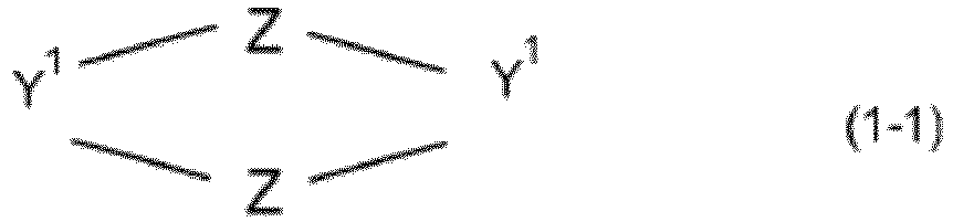 Y1 pour chaque occurrence étant indépendamment un groupe divalent contenant 1 à 30 atomes,ou la formule 1-2
 Y2 pour chaque occurrence étant indépendamment un groupe trivalent contenant 1 à 30 atomes,Z pour chaque occurrence étant indépendamment un groupe organique divalent, Z ayant une séquence la plus courte d'au moins 3 atomes, préférablement 3 à 5 atomes, entre les deux liaisons avec Y1 ou Y2 dans le cas où Y1 ou Y2 est un groupe cyclique relié à chaque Z via des atomes de cycle différents,Z ayant une séquence la plus courte d'au moins 6 atomes, préférablement 6 à 8 atomes, dans le cas où Y1 ou Y2 est relié à chaque Z via un atome,le ligand organique cyclique de formule 1-1 et 1-2 contenant deux groupes monoanioniques liés de manière covalente au ligand organique cyclique et étant séparés l'un de l'autre par une séquence d'au moins deux atomes intervenants, oule composé de coordination comprenant au moins un lanthanide divalent coordiné par un ligand organique cyclique selon la formule 3-1
 • Y1 pour chaque occurrence étant indépendamment un groupe organique divalent, préférablement un groupe cyclique divalent qui possède deux valences au niveau de positions de cycle différentes, ou étant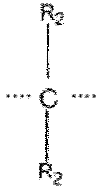
 • Y2 pour chaque occurrence étant indépendamment un groupe organique trivalent, préférablement C-R2 ou un groupe cyclique qui possède trois valences au niveau de positions de cycle différentes, ou étant B ou B-R2 - ou N ou P,• X étant indépendamment choisi pour chaque occurrence dans le groupe de :
 • L pour chaque occurrence indépendamment étant un groupe organique cyclique divalent linéaire, ramifié ou cyclique qui peut être substitué et qui est formé par élimination de deux atomes d'hydrogène d'une molécule organique linéaire, ramifiée ou cyclique qui peut être substituée, ou étant un groupe divalent -CR1R1-• R1 et R2 étant hydrogène ou de quelconques substituants liés de manière covalente qui sont identiques ou différents en chaque occurrence et• n1, n2, i indépendamment étant égaux à 1, 2, 3 ou 4,• le ligand organique cyclique de formule 3-1 et R-2 contenant deux groupes monoanioniques liés de manière covalente au ligand organique cyclique et étant séparés l'un de l'autre par une séquence d'au moins deux atomes intervenants,dans les groupes divalents -CR1R1-, les deux R1 pouvant être liés de manière covalente l'un à l'autre, formant ainsi un groupe cyclique, et dans -CR2R2-, les deux R2 pouvant être liés de manière covalente pour former une structure cyclique.
 - Composé de coordination selon la revendication 3, le composé de formule 3-2 ayant l'une ou plusieurs des caractéristiques suivantes :- Y2 étant B ou B-R2 - ou N, préférablement R2 étant alkyle, alcoxy, carboxy, aryle, aryloxy ou F,- tous les trois éléments structuraux
 - des groupes organiques cycliques divalents L pour chaque occurrence indépendamment étant des groupes organiques cycliques divalents qui peuvent être substitués et qui sont formés par élimination de deux atomes d'hydrogène d'atomes de carbone et/ou d'azote adjacents dans le cycle d'une molécule cyclique organique qui peut être substituée, n1 et n2 étant 1,- des groupes organiques cycliques étant des groupes carbocycliques ou hétérocycliques, les hétéroatome étant choisis parmi P, N, Si, O, S- si dans
 -
-

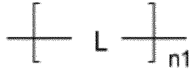
 - i étant 2.
 - Composé de coordination selon l'une quelconque des revendications 3 ou 4, le ligand organique cyclique ayant une structure selon la formule 2a, 2c, 2e ou 2f :

 - R1, R2, R3, R4, R5, R6 dans la formule 2a et 2c indépendamment en chaque occurrence représentant hydrogène ou un substituant, et R1, R2, R3, R4, R5, R6, R7 dans la formule 2e, 2f indépendamment en chaque occurrence représentant hydrogène ou un substituant,- a, b, c étant chacun indépendamment un entier de 0 ou plus,
 ledit ligand organique cyclique de formule 2a et 2c contenant deux groupes monoanioniques liés de manière covalente au ligand organique cyclique et étant séparés l'un de l'autre par une séquence d'au moins deux atomes intervenants, préférablement le groupe monoanionique ayant la charge anionique dans une position β ou γ par rapport à l'atome de carbone ou d'azote de cycle auquel le groupe monoanionique est lié de manière covalente, oudans la formule 2a et 2c,R1 ou R2 pouvant être un groupe monoanionique,ou un atome de carbone de cycle adjacent à N-R1 ou N-R2 pouvant être substitué par un groupe monoanionique,R3 ou R4 pouvant être un groupe monoanionique, ou un atome de carbone de cycle adjacent à N-R3 ou N-R4 pouvant être substitué par un groupe monoanionique, ou R5 ou R6 pouvant être un groupe monoanionique,ou un atome de carbone de cycle adjacent à N-R5 ou N-R6 pouvant être substitué par un groupe monoanionique,avec un total de deux groupes monoanioniques liés de manière covalente au ligand organique cyclique.
 - Composé de coordination selon la revendication 5, le groupe monoanionique ayant la structure-CH2-CR'R'-X, X étant un atome monoanionique choisi parmi O- et S-,ou ayant la structure
 X étant un atome monoanionique choisi parmi O- et S- ,chaque R' étant indépendamment H, alkyle en C1-12 substitué ou non substitué, aryle substitué ou non substitué, halogène, et un R' du groupe monoanionique pouvant être NO2, et deux groupes R' pouvant être liés de manière covalente pour former un groupe cyclique,ou étant choisi parmi les structures suivantes


 R1 à R6 étant indépendamment H ou organyle,R1a à R6a étant indépendamment H, CH3, CF3, CN, F ou CnH2n+1, n étant un entier de 1 à 5,R1b étant CnH2n+1, n étant un entier de 1 à 5,R1c étant CH3 ou CF3,R1d étant un fragment organique divalent, préférablement choisi parmi alkylène, perfluoroalkylène, qui peut éventuellement être substitué,R1e à R3e étant indépendamment un groupe hétéroaryle à 5 chaînons comportant jusqu'à 3 hétéroatomes, choisis parmi N, S, O, qui peut éventuellement être substitué, ou un groupe aryle ou hétéroaryle à 6 chaînons qui peut contenir jusqu'à 4 hétéroatomes, choisis parmi N, S, O, préférablement parmi N, et qui peut éventuellement être substitué, ou un groupe choisi parmi CF3, F, H, OMe, OEtR1f à R11f étant indépendamment H, Cl, Br, F, CH3, CF3 R1g à R4g étant indépendamment H, organyle, halogène, préférablement F, CF3, CN, OMe.
 - Composé de coordination selon la revendication 3, chaque Y1 étant indépendamment choisi parmi

 ou chaque Y1 étant indépendamment choisi parmi des groupes organiques cycliques à 3 à 15 chaînons, préférablement 4 à 12 chaînons qui peuvent contenir 1 à 4 hétéroatomes choisis parmi N, B, P, O, S et étant relié à chaque Z via un carbone ou un hétéroatome non adjacent, R2 étant hydrogène ou un quelconque substituant lié de manière covalente qui est identique ou différent en chaque occurrence, ou chaque Y2 étant indépendamment choisi parmi B, B-R2 -, N, P, C-R2,ou chaque Y2 étant indépendamment choisi parmi des groupes organiques cycliques à 3 à 15 chaînons, préférablement 6 à 12 chaînons qui peuvent contenir un à quatre hétéroatomes choisis parmi N, B, P, O, S et étant relié à chaque Z via un carbone ou un hétéroatome non adjacent,R2 étant hydrogène ou un quelconque substituant lié de manière covalente qui est identique ou différent en chaque occurrence.
 - Composé de coordination selon l'une des revendications 3 ou 7, chaque Z contenant au plus un groupe monoanionique, ou un Z contenant deux groupes monoanioniques et les autres Z, Y1 et Y2 ne contenant pas de groupes monoanioniques.
- Composé de coordination selon l'une des revendications 1 à 8, le ligand organique cyclique contenant exactement deux groupes monoanioniques et par conséquent étant chargé deux fois négativement et en combinaison avec le lanthanide divalent formant un complexe de charge neutre, préférablement le ligand organique cyclique ne contenant pas d'atomes de fluor et plus préférablement ne contenant pas d'atomes d'halogène.
- Mélange comprenantun deuxième composé organique électriquement neutre, etle composé de coordination selon l'une quelconque des revendications 1 à 9,le composé de coordination étant incorporé dans l'au moins un deuxième composé organique électriquement neutre,le deuxième composé organique ayant une énergie triplet supérieure à 2,5 eV et/ou le composé de coordination ayant une affinité de trous plus grande que le deuxième composé organique.
- Composé comprenantle composé de coordination selon l'une quelconque des revendications 1 à 9, etun polymère doté d'un poids moléculaire Mn supérieur à 1 000 g/mole, le composé de coordination étant fixé de manière covalente au squelette du polymère.
- Milieu d'amélioration de contraste pour la tomographie à résonance magnétique (MRT), le milieu d'amélioration de contraste comprenant le composé de coordination selon l'une quelconque des revendications 1 à 9.
- Dispositif électronique organique, comprenant :une première électrode ;une deuxième électrode ; etune couche organique agencée de sorte qu'elle est interposée électriquement entre la première et la deuxième électrodes, la couche organique comprenant le composé de coordination selon l'une quelconque des revendications 1 à 9, le mélange selon la revendication 10 ou le composé selon la revendication 11,préférablement le dispositif électronique organique étant un dispositif optoélectronique, le dispositif optoélectronique étant au moins l'un parmi une diode émettrice de lumière organique, un photodétecteur organique ou une cellule photovoltaïque.
- Procédé de formation d'un dispositif organique, le procédé comprenant :la formation d'une couche du composé de coordination selon l'une quelconque des revendications 1 à 9, ou du mélange selon la revendication 10 ou du composé selon la revendication 11,la couche étant déposée à partir d'une phase gazeuse, en particulier en utilisant un processus d'évaporation et/ou de sublimation, et/ou par un processus à base d'une solution.
- Utilisation d'un composé de coordination métal-organique selon l'une des revendications 1 à 9 dans un dispositif électronique organique, préférablement un dispositif émetteur de lumière organique.
Applications Claiming Priority (2)
| Application Number | Priority Date | Filing Date | Title |
|---|---|---|---|
| PCT/EP2021/059962 WO2021244801A1 (fr) | 2020-06-04 | 2021-04-16 | Composé de coordination métallique-organique et son procédé de production |
| PCT/EP2021/083808 WO2022218562A1 (fr) | 2021-04-16 | 2021-12-01 | Composé de coordination organométallique et son procédé de production |
Publications (2)
| Publication Number | Publication Date |
|---|---|
| EP4323371A1 EP4323371A1 (fr) | 2024-02-21 |
| EP4323371B1 true EP4323371B1 (fr) | 2025-02-05 |
Family
ID=78822467
Family Applications (1)
| Application Number | Title | Priority Date | Filing Date |
|---|---|---|---|
| EP21820253.9A Active EP4323371B1 (fr) | 2021-04-16 | 2021-12-01 | Composé de coordination organométallique et son procédé de production |
Country Status (5)
| Country | Link |
|---|---|
| US (1) | US20240251658A1 (fr) |
| EP (1) | EP4323371B1 (fr) |
| KR (1) | KR20230171937A (fr) |
| CN (1) | CN117157302A (fr) |
| WO (1) | WO2022218562A1 (fr) |
Families Citing this family (9)
| Publication number | Priority date | Publication date | Assignee | Title |
|---|---|---|---|---|
| CN115677736B (zh) * | 2022-10-13 | 2025-12-12 | 北京大学 | 手性d-f跃迁稀土配合物及其作为电致发光材料的应用 |
| EP4389754A1 (fr) * | 2022-12-22 | 2024-06-26 | beeOLED GmbH | Composé de coordination organométallique et son procédé de production |
| EP4467551B1 (fr) | 2023-05-22 | 2026-02-25 | beeOLED GmbH | Composé de coordination organométallique et son procédé de production |
| EP4467631B8 (fr) | 2023-05-22 | 2025-06-18 | beeOLED GmbH | Mélange comprenant un composé de coordination organique à l'europium et son procédé de production |
| EP4502105B1 (fr) | 2023-08-04 | 2025-07-23 | beeOLED GmbH | Composé de coordination organique-europium divalent et son procédé de production |
| EP4501933B1 (fr) | 2023-08-04 | 2025-11-12 | beeOLED GmbH | Composé de coordination organique-europium divalent et son procédé de production |
| EP4503900B1 (fr) | 2023-08-04 | 2025-11-19 | beeOLED GmbH | Dispositif électroluminescent comprenant un composé de coordination organique à l'europium et son procédé de production |
| EP4606804A1 (fr) | 2024-02-22 | 2025-08-27 | beeOLED GmbH | Procédé de préparation de closo-carborates substitués par de l'oxygène |
| EP4658039A1 (fr) | 2024-05-27 | 2025-12-03 | beeOLED GmbH | Dispositif électroluminescent comprenant un composé de coordination organométallique avec un spin électronique en tant que matériau hôte |
Family Cites Families (7)
| Publication number | Priority date | Publication date | Assignee | Title |
|---|---|---|---|---|
| GB9820805D0 (en) | 1998-09-25 | 1998-11-18 | Isis Innovation | Divalent lanthanide metal complexes |
| US7811676B2 (en) | 2002-12-24 | 2010-10-12 | Merck Patent Gmbh | Electroluminescent materials and devices |
| JP3651801B2 (ja) | 2003-06-30 | 2005-05-25 | 九州電力株式会社 | 電界発光素子 |
| US9655982B2 (en) | 2010-01-19 | 2017-05-23 | Wayne State University | Formation and uses of europium complexes |
| JP2012254973A (ja) * | 2011-05-18 | 2012-12-27 | Sumitomo Chemical Co Ltd | 脂肪族アミン配位セリウム錯体及び該錯体を含む素子 |
| EP2968150B1 (fr) | 2013-03-11 | 2020-08-19 | Wayne State University | Liposomes comprennant europium cryptands et leur utilisation |
| EP3774025A4 (fr) * | 2018-03-27 | 2021-12-29 | Selux Diagnostics, Inc. | Système, procédé et interface pour le traitement en parallèle d'essais de susceptibilité antimicrobienne à l'aide de différents échantillons |
-
2021
- 2021-12-01 US US18/287,129 patent/US20240251658A1/en active Pending
- 2021-12-01 CN CN202180097133.3A patent/CN117157302A/zh active Pending
- 2021-12-01 EP EP21820253.9A patent/EP4323371B1/fr active Active
- 2021-12-01 WO PCT/EP2021/083808 patent/WO2022218562A1/fr not_active Ceased
- 2021-12-01 KR KR1020237035280A patent/KR20230171937A/ko active Pending
Also Published As
| Publication number | Publication date |
|---|---|
| KR20230171937A (ko) | 2023-12-21 |
| CN117157302A (zh) | 2023-12-01 |
| US20240251658A1 (en) | 2024-07-25 |
| WO2022218562A1 (fr) | 2022-10-20 |
| EP4323371A1 (fr) | 2024-02-21 |
Similar Documents
| Publication | Publication Date | Title |
|---|---|---|
| EP4323371B1 (fr) | Composé de coordination organométallique et son procédé de production | |
| KR102805243B1 (ko) | 유기 전계발광 물질 및 디바이스 | |
| WO2021244801A1 (fr) | Composé de coordination métallique-organique et son procédé de production | |
| EP2635561B1 (fr) | Composé de xanthone et dispositif électroluminescent organique l'incluant | |
| TW201231459A (en) | Electroactive compositions for electronic applications | |
| US20250122228A1 (en) | Metal-organic coordination compound comprising cerium(iii) | |
| US20230345815A1 (en) | Metal-organic coordination compound and method for producing the same | |
| CN112390828A (zh) | 有机电致发光材料和装置 | |
| CN114478483A (zh) | 有机电致发光材料和装置 | |
| CN112300204A (zh) | 有机电致发光材料和装置 | |
| EP4389754A1 (fr) | Composé de coordination organométallique et son procédé de production | |
| EP4467551A1 (fr) | Composé de coordination organométallique et son procédé de production | |
| US20260007065A1 (en) | Electroluminescent device comprising a metal organic coordination compound with electronic spin as host material | |
| US20210280804A1 (en) | Organic electroluminescent materials and devices | |
| US20200308196A1 (en) | Organic electroluminescent materials and devices | |
| EP4502105B1 (fr) | Composé de coordination organique-europium divalent et son procédé de production | |
| CN112430248A (zh) | 有机电致发光材料和装置 | |
| EP4467631A1 (fr) | Mélange comprenant un composé de coordination organique à l'europium et son procédé de production | |
| US11616203B2 (en) | Organic electroluminescent materials and devices | |
| WO2025032014A1 (fr) | Dispositif électroluminescent comprenant un composé de coordination organique d'europium et son procédé de production | |
| CN121873130A (zh) | 有机电致发光材料和装置 | |
| CN119638730A (zh) | 有机电致发光材料和装置 | |
| CN121873131A (zh) | 有机电致发光材料和装置 | |
| CN120682267A (zh) | 一种链状硅化合物及其应用 | |
| CN113497210A (zh) | 有机电致发光材料和装置 |
Legal Events
| Date | Code | Title | Description |
|---|---|---|---|
| STAA | Information on the status of an ep patent application or granted ep patent |
Free format text: STATUS: UNKNOWN |
|
| STAA | Information on the status of an ep patent application or granted ep patent |
Free format text: STATUS: THE INTERNATIONAL PUBLICATION HAS BEEN MADE |
|
| PUAI | Public reference made under article 153(3) epc to a published international application that has entered the european phase |
Free format text: ORIGINAL CODE: 0009012 |
|
| STAA | Information on the status of an ep patent application or granted ep patent |
Free format text: STATUS: REQUEST FOR EXAMINATION WAS MADE |
|
| 17P | Request for examination filed |
Effective date: 20231026 |
|
| AK | Designated contracting states |
Kind code of ref document: A1 Designated state(s): AL AT BE BG CH CY CZ DE DK EE ES FI FR GB GR HR HU IE IS IT LI LT LU LV MC MK MT NL NO PL PT RO RS SE SI SK SM TR |
|
| STAA | Information on the status of an ep patent application or granted ep patent |
Free format text: STATUS: EXAMINATION IS IN PROGRESS |
|
| 17Q | First examination report despatched |
Effective date: 20240506 |
|
| DAV | Request for validation of the european patent (deleted) | ||
| DAX | Request for extension of the european patent (deleted) | ||
| GRAP | Despatch of communication of intention to grant a patent |
Free format text: ORIGINAL CODE: EPIDOSNIGR1 |
|
| STAA | Information on the status of an ep patent application or granted ep patent |
Free format text: STATUS: GRANT OF PATENT IS INTENDED |
|
| RIC1 | Information provided on ipc code assigned before grant |
Ipc: C07F 9/06 20060101ALI20240716BHEP Ipc: H10K 85/60 20230101ALI20240716BHEP Ipc: C09K 11/06 20060101ALI20240716BHEP Ipc: C07F 5/00 20060101ALI20240716BHEP Ipc: C07F 5/02 20060101ALI20240716BHEP Ipc: C07F 9/26 20060101AFI20240716BHEP |
|
| INTG | Intention to grant announced |
Effective date: 20240730 |
|
| GRAS | Grant fee paid |
Free format text: ORIGINAL CODE: EPIDOSNIGR3 |
|
| GRAA | (expected) grant |
Free format text: ORIGINAL CODE: 0009210 |
|
| STAA | Information on the status of an ep patent application or granted ep patent |
Free format text: STATUS: THE PATENT HAS BEEN GRANTED |
|
| AK | Designated contracting states |
Kind code of ref document: B1 Designated state(s): AL AT BE BG CH CY CZ DE DK EE ES FI FR GB GR HR HU IE IS IT LI LT LU LV MC MK MT NL NO PL PT RO RS SE SI SK SM TR |
|
| REG | Reference to a national code |
Ref country code: GB Ref legal event code: FG4D |
|
| REG | Reference to a national code |
Ref country code: CH Ref legal event code: EP |
|
| REG | Reference to a national code |
Ref country code: DE Ref legal event code: R096 Ref document number: 602021025776 Country of ref document: DE |
|
| REG | Reference to a national code |
Ref country code: IE Ref legal event code: FG4D |
|
| REG | Reference to a national code |
Ref country code: NL Ref legal event code: FP |
|
| RAP4 | Party data changed (patent owner data changed or rights of a patent transferred) |
Owner name: BEEOLED GMBH |
|
| PG25 | Lapsed in a contracting state [announced via postgrant information from national office to epo] |
Ref country code: RS Free format text: LAPSE BECAUSE OF FAILURE TO SUBMIT A TRANSLATION OF THE DESCRIPTION OR TO PAY THE FEE WITHIN THE PRESCRIBED TIME-LIMIT Effective date: 20250505 |
|
| PG25 | Lapsed in a contracting state [announced via postgrant information from national office to epo] |
Ref country code: FI Free format text: LAPSE BECAUSE OF FAILURE TO SUBMIT A TRANSLATION OF THE DESCRIPTION OR TO PAY THE FEE WITHIN THE PRESCRIBED TIME-LIMIT Effective date: 20250205 |
|
| PG25 | Lapsed in a contracting state [announced via postgrant information from national office to epo] |
Ref country code: PL Free format text: LAPSE BECAUSE OF FAILURE TO SUBMIT A TRANSLATION OF THE DESCRIPTION OR TO PAY THE FEE WITHIN THE PRESCRIBED TIME-LIMIT Effective date: 20250205 |
|
| PG25 | Lapsed in a contracting state [announced via postgrant information from national office to epo] |
Ref country code: ES Free format text: LAPSE BECAUSE OF FAILURE TO SUBMIT A TRANSLATION OF THE DESCRIPTION OR TO PAY THE FEE WITHIN THE PRESCRIBED TIME-LIMIT Effective date: 20250205 |
|
| REG | Reference to a national code |
Ref country code: LT Ref legal event code: MG9D |
|
| PG25 | Lapsed in a contracting state [announced via postgrant information from national office to epo] |
Ref country code: IS Free format text: LAPSE BECAUSE OF FAILURE TO SUBMIT A TRANSLATION OF THE DESCRIPTION OR TO PAY THE FEE WITHIN THE PRESCRIBED TIME-LIMIT Effective date: 20250605 Ref country code: NO Free format text: LAPSE BECAUSE OF FAILURE TO SUBMIT A TRANSLATION OF THE DESCRIPTION OR TO PAY THE FEE WITHIN THE PRESCRIBED TIME-LIMIT Effective date: 20250505 |
|
| PG25 | Lapsed in a contracting state [announced via postgrant information from national office to epo] |
Ref country code: HR Free format text: LAPSE BECAUSE OF FAILURE TO SUBMIT A TRANSLATION OF THE DESCRIPTION OR TO PAY THE FEE WITHIN THE PRESCRIBED TIME-LIMIT Effective date: 20250205 |
|
| PG25 | Lapsed in a contracting state [announced via postgrant information from national office to epo] |
Ref country code: LV Free format text: LAPSE BECAUSE OF FAILURE TO SUBMIT A TRANSLATION OF THE DESCRIPTION OR TO PAY THE FEE WITHIN THE PRESCRIBED TIME-LIMIT Effective date: 20250205 Ref country code: PT Free format text: LAPSE BECAUSE OF FAILURE TO SUBMIT A TRANSLATION OF THE DESCRIPTION OR TO PAY THE FEE WITHIN THE PRESCRIBED TIME-LIMIT Effective date: 20250605 |
|
| PG25 | Lapsed in a contracting state [announced via postgrant information from national office to epo] |
Ref country code: BG Free format text: LAPSE BECAUSE OF FAILURE TO SUBMIT A TRANSLATION OF THE DESCRIPTION OR TO PAY THE FEE WITHIN THE PRESCRIBED TIME-LIMIT Effective date: 20250205 Ref country code: GR Free format text: LAPSE BECAUSE OF FAILURE TO SUBMIT A TRANSLATION OF THE DESCRIPTION OR TO PAY THE FEE WITHIN THE PRESCRIBED TIME-LIMIT Effective date: 20250506 |
|
| REG | Reference to a national code |
Ref country code: AT Ref legal event code: MK05 Ref document number: 1764880 Country of ref document: AT Kind code of ref document: T Effective date: 20250205 |
|
| PG25 | Lapsed in a contracting state [announced via postgrant information from national office to epo] |
Ref country code: SE Free format text: LAPSE BECAUSE OF FAILURE TO SUBMIT A TRANSLATION OF THE DESCRIPTION OR TO PAY THE FEE WITHIN THE PRESCRIBED TIME-LIMIT Effective date: 20250205 |
|
| PG25 | Lapsed in a contracting state [announced via postgrant information from national office to epo] |
Ref country code: SM Free format text: LAPSE BECAUSE OF FAILURE TO SUBMIT A TRANSLATION OF THE DESCRIPTION OR TO PAY THE FEE WITHIN THE PRESCRIBED TIME-LIMIT Effective date: 20250205 |
|
| PG25 | Lapsed in a contracting state [announced via postgrant information from national office to epo] |
Ref country code: DK Free format text: LAPSE BECAUSE OF FAILURE TO SUBMIT A TRANSLATION OF THE DESCRIPTION OR TO PAY THE FEE WITHIN THE PRESCRIBED TIME-LIMIT Effective date: 20250205 |
|
| PG25 | Lapsed in a contracting state [announced via postgrant information from national office to epo] |
Ref country code: IT Free format text: LAPSE BECAUSE OF FAILURE TO SUBMIT A TRANSLATION OF THE DESCRIPTION OR TO PAY THE FEE WITHIN THE PRESCRIBED TIME-LIMIT Effective date: 20250205 |
|
| PG25 | Lapsed in a contracting state [announced via postgrant information from national office to epo] |
Ref country code: AT Free format text: LAPSE BECAUSE OF FAILURE TO SUBMIT A TRANSLATION OF THE DESCRIPTION OR TO PAY THE FEE WITHIN THE PRESCRIBED TIME-LIMIT Effective date: 20250205 |
|
| PG25 | Lapsed in a contracting state [announced via postgrant information from national office to epo] |
Ref country code: EE Free format text: LAPSE BECAUSE OF FAILURE TO SUBMIT A TRANSLATION OF THE DESCRIPTION OR TO PAY THE FEE WITHIN THE PRESCRIBED TIME-LIMIT Effective date: 20250205 Ref country code: CZ Free format text: LAPSE BECAUSE OF FAILURE TO SUBMIT A TRANSLATION OF THE DESCRIPTION OR TO PAY THE FEE WITHIN THE PRESCRIBED TIME-LIMIT Effective date: 20250205 |
|
| PG25 | Lapsed in a contracting state [announced via postgrant information from national office to epo] |
Ref country code: RO Free format text: LAPSE BECAUSE OF FAILURE TO SUBMIT A TRANSLATION OF THE DESCRIPTION OR TO PAY THE FEE WITHIN THE PRESCRIBED TIME-LIMIT Effective date: 20250205 |
|
| PG25 | Lapsed in a contracting state [announced via postgrant information from national office to epo] |
Ref country code: SK Free format text: LAPSE BECAUSE OF FAILURE TO SUBMIT A TRANSLATION OF THE DESCRIPTION OR TO PAY THE FEE WITHIN THE PRESCRIBED TIME-LIMIT Effective date: 20250205 |
|
| REG | Reference to a national code |
Ref country code: DE Ref legal event code: R097 Ref document number: 602021025776 Country of ref document: DE |
|
| PLBE | No opposition filed within time limit |
Free format text: ORIGINAL CODE: 0009261 |
|
| STAA | Information on the status of an ep patent application or granted ep patent |
Free format text: STATUS: NO OPPOSITION FILED WITHIN TIME LIMIT |
|
| PGFP | Annual fee paid to national office [announced via postgrant information from national office to epo] |
Ref country code: GB Payment date: 20251229 Year of fee payment: 5 |
|
| 26N | No opposition filed |
Effective date: 20251106 |
|
| PGFP | Annual fee paid to national office [announced via postgrant information from national office to epo] |
Ref country code: FR Payment date: 20251223 Year of fee payment: 5 Ref country code: NL Payment date: 20251223 Year of fee payment: 5 |
|
| PGFP | Annual fee paid to national office [announced via postgrant information from national office to epo] |
Ref country code: DE Payment date: 20251230 Year of fee payment: 5 |