EP4323595B1 - Dispositif de drainage doté d'un support réglable pour un couvercle de drain - Google Patents
Dispositif de drainage doté d'un support réglable pour un couvercle de drain Download PDFInfo
- Publication number
- EP4323595B1 EP4323595B1 EP22714870.7A EP22714870A EP4323595B1 EP 4323595 B1 EP4323595 B1 EP 4323595B1 EP 22714870 A EP22714870 A EP 22714870A EP 4323595 B1 EP4323595 B1 EP 4323595B1
- Authority
- EP
- European Patent Office
- Prior art keywords
- holder
- receiver
- fixing element
- drain device
- drain
- Prior art date
- Legal status (The legal status is an assumption and is not a legal conclusion. Google has not performed a legal analysis and makes no representation as to the accuracy of the status listed.)
- Active
Links
Images




Classifications
-
- E—FIXED CONSTRUCTIONS
- E03—WATER SUPPLY; SEWERAGE
- E03F—SEWERS; CESSPOOLS
- E03F5/00—Sewerage structures
- E03F5/04—Gullies inlets, road sinks, floor drains with or without odour seals or sediment traps
- E03F5/0407—Floor drains for indoor use
- E03F5/0408—Floor drains for indoor use specially adapted for showers
-
- B—PERFORMING OPERATIONS; TRANSPORTING
- B01—PHYSICAL OR CHEMICAL PROCESSES OR APPARATUS IN GENERAL
- B01D—SEPARATION
- B01D29/00—Filters with filtering elements stationary during filtration, e.g. pressure or suction filters, not covered by groups B01D24/00 - B01D27/00; Filtering elements therefor
- B01D29/01—Filters with filtering elements stationary during filtration, e.g. pressure or suction filters, not covered by groups B01D24/00 - B01D27/00; Filtering elements therefor with flat filtering elements
- B01D29/05—Filters with filtering elements stationary during filtration, e.g. pressure or suction filters, not covered by groups B01D24/00 - B01D27/00; Filtering elements therefor with flat filtering elements supported
Definitions
- the invention relates to a drainage device for installation in an opening of a floor slab according to the preamble of claim 1 and to a floor slab with such a drainage device.
- a floor slab is understood to be a system that can be integrated into a building structure and which collects water and feeds it to a drainage system integrated into the floor slab.
- Such floor tiles can be used for a variety of applications. For example, they can be installed in sanitary areas, especially in showers. They can also be used in other types of wet rooms with floor drains, such as kitchens, public buildings such as hospitals, or food processing facilities such as commercial kitchens or slaughterhouses. They can also be used outdoors, for example, on balconies and terraces.
- a shower floor which comprises a base plate (support element 12) and a cover layer element 17.
- the cover layer element 17 can have a frame 20 with a shoulder 24 inserted into an opening.
- the opening of the cover layer element coincides with a drain opening 13 provided in the support element 12 in such a way that the shoulder 24 of the frame 20 can be inserted into the drain opening 13.
- the assembly of the cover layer element 17 and The support element 12 is assembled by gluing the two parts together. After assembly, the drain is fixed in position. This also predetermines the position of a cover that can be placed over the drain opening. Only if the cover and the cover layer element have the same center axis will the joint surrounding the cover be the same width on all sides. The disadvantage is that even small deviations between the two center axes are visually noticeable, as the outer sides of the joints surrounding the cover will then have different widths.
- a drainage device with the features of the preamble of claim 1 is known.
- an extension element screwed into the holder can be screwed out of or into the holder if handled in an incompetent manner, thus incorrectly adjusting the height of the inlet.
- the object of the invention is therefore to further develop the drainage device of D1 so that its assembly is less prone to errors.
- the cover can be a plastic or metal part with point-shaped, linear, or other openings for the passage of wastewater.
- wastewater refers to any type of liquid that is to be drained through the drain. This wastewater can therefore be, for example, shower water (used in sanitary areas), rainwater (used outdoors), or other liquids such as cleaning agents, suspensions, etc. (used in industrial areas).
- the cover can be mounted directly on the extension element. Between however, additional parts, such as intermediate supports, can also be arranged in addition to the extension element and cover.
- the aforementioned pre-assembled state of the adjustment device refers to the state in which the holder, bracket, and fixing element are located after the bracket has been inserted into the holder and secured by the fixing element, leaving some play.
- the adjustment device assembled in this way is a component of the drain device.
- the bracket inserted into the holder is movable until it is finally fixed in its final position (assembled state) after the drain device has been installed in a floor slab and the floor slab has been installed in a designated location, and after fine adjustment relative to the surrounding floor covering.
- the mount and the fixing element form a kind of housing around the holder.
- the holder is thus freely movable within this housing-like structure within a certain vertical and horizontal clearance.
- This flexibility of the holder allows for fine adjustment of the cover relative to the surrounding floor after the floor covering has been applied. If the floor covering is made of tiles, for example, it is sufficient to initially apply the tiles with a relatively large tolerance so that the drain is positioned relatively roughly within an area left free in the floor covering. In concrete terms, a tolerance range arises when applying the floor covering because the width of the joints surrounding the drain is not determined during tiling, but rather by fine-tuning the drain after the Applying the floor covering. The specified tolerance range is as large as the clearance of the cover plate holder relative to the mount.
- the holder and the cover directly or indirectly connected to the holder can be easily aligned or finely adjusted manually within the specified clearance, either by eye or with the aid of spacers, relative to the surrounding floor covering.
- the position of the cover support can be finally fixed by filling the now evenly spaced joints with a suitable adhesive or mortar.
- the drain device After the drain device has been finally bonded to the floor covering, the holder is secured in the mount and the previously existing play is eliminated. The drain device is then in its assembled state.
- the horizontal play of the holder relative to the receptacle in the pre-assembled state is at least 1 mm, most preferably 3 mm to 8 mm.
- This amount of play is sufficient to enable the desired fine adjustment and is also adapted to the joint widths specified in DIN 18 157.
- DIN 18 157 recommends a joint width that depends on the side length of your tile. Up to a side length of 150 mm, joints with a width of around 2 mm can be created. For side lengths of 150 mm and longer, a joint width of at least 2 mm and up to 8 mm should be selected.
- the vertical clearance of the holder between the receptacle and the fixing element is preferably 0.1 to 2 mm. This clearance is sufficient to prevent the holder from being pinched by the fixing element, while also being small enough to keep the drain assembly flat overall in terms of its installation height.
- a flat installation height is particularly advantageous for shower trays designed for flush-to-floor installation.
- the holder has an internal thread and the extension element for the cover has a screwable into the internal thread External thread.
- This makes it possible to adjust the installation height of the extension element relative to the floor slab. Since the extension element supports the cover, the height of the cover's upper surface can be precisely adjusted to the height of the surrounding floor covering.
- the drain device is therefore independent of the thickness of the floor covering used and can be adapted to floor coverings of different thicknesses. The position of the cover can therefore be varied vertically as well as horizontally.
- the inner contour of the receptacle and/or the outer contour of the holder are round. If both contours are round, the inner contour forms a smaller cylinder and the outer contour a larger cylinder, with the smaller cylinder being freely movable horizontally within the larger cylinder. If both contours are cylindrical, equal play in all horizontal directions is achieved within a small space.
- the fixing element can preferably be a locking ring.
- a locking ring is easy to handle and reliably secures the position of the holder in the housing.
- the fixing element and the holder can be coupled together using a locking or snap-in connection.
- the locking or snap-in connection which can be detachable or non-detachable, allows the aforementioned components to be easily joined together in a form-fitting manner.
- the locking connection is formed by at least one projection provided on the fixing element and at least one recess provided in the receptacle, into which said projection can be locked.
- the projection deforms elastically and subsequently hooks into the recess of the receptacle.
- a recess is provided on the top side of the holder. Furthermore, it is provided that the fixing element has a projection that can be inserted into the recess and is arranged within the recess when mounted. This limits the play of the holder relative to the fixing element in the horizontal direction. The holder - and thus also a cover coupled to the holder - is therefore no longer freely movable within the initially provided horizontal play. Rather, the initially existing play is further limited by the combination of the recess on the holder and the projection on the fixing element. As a result, a holder with a projection is only as movable as the size of the recess allows.
- the object of the invention is further achieved by a base plate, preferably
- a shower base plate comprising a drainage device according to one of claims 1 to 9.
- the drainage device can be fully or partially pre-assembled in the shower base plate. Even with such a base plate, the inventive mobility of the cover, or the mobility of the parts supporting and holding the cover, relative to the base plate is present in the pre-assembled state.
- the base plate can be installed first, then the floor covering can be applied. After the floor covering has been applied, the cover can be finely adjusted relative to the surrounding floor covering and then finally fixed in the desired position by applying adhesive.
- Figure 1 shows a sectional view of a drainage device 100 installed in a floor plate 10.
- the floor plate 10 is a shower floor plate 11, which has a
- Inlet opening 13 has a gradient. Wastewater entering through the inlet opening 13 is fed to a pipe system 16 connected to the drainage device 100.
- the illustrated embodiment is a drain device 100 installed in a sanitary room, which is installed in an opening 12 of the shower base plate 11.
- the drain device 100 shown does not include an odor trap integrated into the drain pot. In other embodiments, the drain device itself may also include an odor trap.
- FIG. 2 shows the shower floor panel 11 with the drain device 100 in a sectional view.
- An adapter 200 is attached to the drain pipe 16 and fixed at a first coupling point 41 by means of a press connection 56.
- the adapter 200 is screwed to a receptacle 40 by means of a screw connection 62.
- a bayonet lock 63 is integrated into the screw connection 62. The bayonet lock 63 facilitates the alignment of the components to be screwed together.
- the receptacle 40 together with a holder 25 and a fixing element 30, which in this case is a locking ring 33, forms an adjusting device 150.
- the holder 25 of the adjusting device 150 is connected to an extension element 15 via a thread.
- An intermediate support 66 can be arranged on the extension element 15, on which a cover 14 is provided for closing the inlet opening 13.
- the cover 14 is removable for cleaning and maintenance work. In the fully assembled state, the surface of the cover 14 is preferably aligned flush with the surface of a covering applied to the shower floor 11, which can be, for example, floor tiles.
- the adjustment device 150 enables, on the one hand, the described height alignment and, on the other hand, a horizontal adjustment of the cover 14 for uniform alignment with the joints surrounding the cover 14.
- Figure 3 shows the components of the drainage device 100 in an exploded view.
- the cover 14 can preferably be placed in a form-fitting manner on an intermediate support 66 provided in the illustrated embodiment.
- the intermediate support 66 can also have form-fitting contours and thus be placed in a form-fitting manner on the extension element 15.
- the extension element 15 has an external thread 17 which can be screwed into an internal thread 29 of the holder 25.
- the holder 25 is held in a preassembled state Z1 in a housing-like structure and is movable within this housing-like structure.
- the housing-like structure is located in an area between the fixing element 30—in this case, the locking ring 33—and the receptacle 40.
- the receptacle 40 can be inserted from above into the opening 12 of the base plate 10.
- the holder 25, the locking ring 33, the extension element 15, the intermediate support 66, and the cover 14 are also inserted from above into the drain device 100 and can be easily removed if necessary, for example, for cleaning work.
- a base part 20 provided on the adapter 200 is first attached from below to the receptacle 40 already inserted into the base plate 10.
- the base part 20 is fixed to the drain pipe 16 by means of the press connection 56, which is formed by the sealing ring 43, the spacer 49, the press ring 44, and the insert part 45.
- the exact functionality is explained in more detail below.
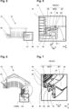
- FIG. 5 an enlarged section A1 from Fig. 4 and Fig. 7 an enlarged section A2 from Fig. 6 .
- the adjustment device 150 is shown in the preassembled state Z1.
- the extension element 15 is screwed with its external thread 17 into the internal thread 29 of the holder 25.
- the holder 25 has a circumferential flange 67 with an outer contour 26.
- the flange 67 rests on a support surface 21 present in the receptacle 40 (cf. Fig. 12 ).
- a locking ring 33 provided with projections 34 is inserted into recesses 23 of the Receptacle 40 is engaged.
- the projections 34 and the recesses 23 form a locking connection 18 between the locking ring 33 and the receptacle 40.
- Locking ring 33 and receptacle 40 thus form a housing-like structure that has approximately the shape of a horizontal U or a circumferential groove open towards the central axis. In the preassembled state Z1, this groove encloses the flange of the holder 25.
- the holder 25 - and thus also the extension element 15 - are movable in the horizontal direction RH and vertical direction RV within the groove.
- This mobility is expressed by a horizontal play SH, which in the illustrated embodiment is 5 mm, and a vertical play SV, which is less than 1 mm and serves to prevent the flange 67 from becoming trapped between the locking ring 33 and the receptacle 40.
- the horizontal and vertical play are maintained until a floor covering is applied to the shower floor panel 11.
- a floor covering is applied to the shower floor panel 11.
- the floor panel 10 and the drainage device 100 are first installed. Once the floor panel is in place and connected to the pipe 16, a floor covering (not shown in the drawings) is applied to the floor panel. After the floor covering has been applied, the height of the cover 14 placed on the extension element 15 can be precisely adjusted to the height of the floor covering by screwing the extension element 15 into the holder 25. Furthermore, the horizontal positioning of the cover 14 is also finely adjustable, since the adjusting device 150 is still in the pre-assembled state Z1 at this time.
- the adjustment device 150 After the position of the cover 14 has been finely adjusted in the vertical and horizontal directions RV, RH, the remaining open joints around the cover 14 are finally sealed with a suitable mortar. This converts the adjustment device 150 from the pre-assembled state Z1 to a fully assembled state. In the fully assembled state, the adjustment device 150 is thus fixed, and only the cover 14 can still be removed from its holder.
- the Figures 8 and 9 show a fixing element 30 in the form of a locking ring 33 in a perspective view obliquely from above ( Fig. 8 ) and diagonally below ( Fig. 9 ).
- the locking ring 33 is made of a flexible plastic and comprises four projections 34, which can be inserted into the compatible recesses 23 of the receptacle 40 to produce a locking connection 18.
- the The locking ring 33 has several through openings 19 which, when fully assembled, serve to drain away seepage water penetrating into the drain.
- Fig. 9 also shows a projection 36 attached to the underside 32 of the locking ring 33, which in the pre-assembled state Z1 of the adjusting device 150 is arranged in a recess 35 provided in the holder 25 and there limits the horizontal play SH of the holder 25.
- Fig. 10 shows the extension element 15, which has a tubular contour with an external thread 17 and a flange 69 adjoining the tubular contour. Openings 69 are provided in the tubular contour, which, analogous to the openings 19 in the locking ring 33, serve to drain seepage water.
- the tubular contour can be shortened by a length 70 on site, for example, using a cutter knife, to adapt to the thickness of a floor covering to be applied.
- Fig. 11 shows the holder 25, which also has openings 24 for draining seepage water.
- the holder 25 has an internal thread 29 into which the extension element 15 can be screwed.
- the holder 25 includes the aforementioned recess 35 to limit its mobility in the horizontal direction RH.
- the holder 25 also has a flange 67 with a circular outer contour 26.
- the outer contour 26 has a diameter D1 that is smaller than a diameter D2 of the receptacle 40. The holder 25 can thus be inserted into the receptacle 40.
- the Figures 12 to 14 show the shower base plate 11 with inserted holder 40 in different pre-assembly stages.
- Figure 13 shows the holder 40 with the holder 25 inserted.
- the holder 25 rests with its flange 67 on the support surface 21 of the holder 40 and is movable in the horizontal direction RH within the horizontal play SH.
- Fig. 14 shows the holder 40 with a mounted locking ring 33.
- the locking ring 33 is detachably connected to the holder 40 via the locking connection 18.
- This installation situation represents the pre-assembled state Z1, in which the holder 25 (in Fig. 14 not shown) is movable in the housing-like structure formed by the locking ring 33 and the receptacle 40 and can thus be adjusted if necessary.
- the Figures 15 to 23 show the adapter 200 and its components already mentioned above.
- the adapter 200 serves to watertightly couple a water inlet inserted into the base plate 10 to the drain pipe 16.
- the adapter 200 thus has two coupling points, namely the first coupling point 41, at which it is coupled to the drain pipe 16, and the second coupling point 42, at which it is coupled to the water inlet or to the receptacle 40 integrated into the water inlet (cf. Fig. 2 ).
- the drainage device 100 comprises both an adjusting device 150 and an adapter 200.
- the details of the receptacle 40 with special features for integrating an adjusting device 150 have already been explained above.
- the adjusting device 150 it is irrelevant whether a drainage device on which the adjusting device 150 is to be used comprises an adapter 200.
- the adapter 200 it is also irrelevant whether the drainage device 100 comprises an adjusting device 150. Rather, both assemblies can be universally integrated into a drainage device, either alone or together.
- the Figures 15 and 16 show the drain device 100, which on the one hand comprises the adapter 200 and on the other hand is also intended to integrate an adjusting device 150. This is evident from the fact that the Figures 15 and 16 shown receptacle 40 also includes features of the adjustment device 150.
- the adapter 200 comprises two coupling points 41 and 42.
- the function of the adapter 200 in connection with the first coupling point 41 is to create a watertight connection between the base part 20 and the drain pipe 16.
- This fixed connection is the one already described in connection with Fig. 2 mentioned press connection 56.
- the press connection 56 relative to the drain pipe 16 is realized solely by an adapter with the components base part 20, sealing ring 43, and press ring 44.
- the adapter 200 further comprises the spacer 49 and the insert part 45.
- the press connection 56 is realized by a screw connection 38.
- the screw connection 38 is formed by an internal thread 54 arranged on the base part 20 and an external thread 55 arranged on the press ring 44.
- the press ring 44 can thus be screwed into the base part 20.
- the base part 20 has on its underside a lower collar 48 with an internal diameter D3 that is smaller than an external diameter D4 provided on the sealing ring 43.
- the adapter 200 further comprises the spacer 49 and the insert part 45.
- these parts are not absolutely necessary for producing the press connection 56.
- the press connection 56 can also be produced by pressing the press ring 44 directly against the sealing ring 43 without the spacer 49 acting as a spacer.
- the press ring could, for example, have a cylindrical contour similar to the contour of the spacer, so that the press ring functions simultaneously as a spacer and as a pressing means.
- an insert part 45 in the adapter 200 is also not mandatory.
- the insert part 45 is provided for screwing the press ring 44 into the base part 20.
- This insert part 45 comprises connecting elements 46' for establishing a positive connection 47 with compatible connecting elements 46 on the press ring 44.
- the insert part 45 comprises a receptacle 59, which in the illustrated embodiment is a slot for inserting a screwdriver. Using the screwdriver, the insert part 45 and the press ring 44 coupled to the insert part can be easily screwed into the base part 20.
- the insert part 45 thus forms a screwing aid. Even without the insert part 45, the press ring 44 can be screwed into the base part 20. If an adapter 200 is to be used without the insert part 45, the press ring 44 could, for example, comprise a shoulder onto which a screwing tool can be directly placed, so that a sufficiently strong press connection can be established even without the use of the insert part 45.
- FIGS 17 and 18 show the base part 20 of the adapter 200.
- the lower collar 48 which has the inner diameter D3.
- the sealing ring 43 is arranged on the lower collar 48.
- the base part 20 has an upper collar 50 with a U-shaped recess 65, into which a seal 39 is glued.
- the base part 20 has an external thread 60 arranged on the upper collar 50, which, together with an internal thread 61 arranged on the receptacle 40, forms a screw connection 62 and thus the second coupling point 42.
- the circular seal 39 glued into the base part 20 is provided in the illustrated embodiment.
- the external thread 60 is arranged on the upper collar 50 of the base part 20 and comprises part of a bayonet lock 63.
- the other part of the bayonet lock 63 is integrated into the internal thread 61 of the receptacle 40 (cf. Fig. 7 ).
- the engagement of the catch 64 can be felt during screwing in, so that the person installing the drain device 100 receives a haptic and/or acoustic signal that the predefined screwing depth has been reached.
- the base part 20 can only be unscrewed from the receptacle 40 if the catch 64 has previously been pushed out of the recess, for example by means of a screwdriver.
- the catch 64 thus secures the base part 20 against unintentional unscrewing.
- the Figures 19 and 20 show the spacer 49 provided in the illustrated embodiment.
- the spacer 49 has a cylindrical shape and acts as a spacer between the pressing ring 44 and the sealing ring 43.
- the spacer 49 is pushed linearly along its central axis into the base part 20 and finally presses on the sealing ring 43.
- the sealing ring 43 is in turn supported on the lower collar 48 of the base part 20 and is screwed in by the pressing ring 44 squeezed and forms the press connection 56.
- the spacer 49 also comprises a glued-in sealing ring 52 which is dimensioned such that, in the assembled state, it forms a low-resistance press fit with the drain pipe 16.
- the spacer 49 also has two predetermined separation points 53, at which it can be easily separated into two half-shell-like individual parts, for example, using a utility knife.
- two predetermined separation points 53 at which it can be easily separated into two half-shell-like individual parts, for example, using a utility knife.
- such a division of the spacer 49 is particularly helpful if, during assembly, a spacer 49 was accidentally forgotten to be inserted into the base part 20 and, moreover, the upper inlet opening of the drainage device 100 is too small to subsequently push the spacer 49 through and place it in the intended location.
- a spacer 49 divided into two half-shells can thus also be pushed through an inlet opening that is too small for an undivided spacer 49.
- the Figure 21 shows the sealing ring 43, which is a standard sealing ring made of a flexible material with an outer diameter D4.
- Figure 22 shows the pressing ring 44 with the connecting elements 46 arranged on the upper side for establishing the positive connection 47 to the insert part 45. Furthermore, a flattened area can be seen on the external thread 55, which forms part of the bayonet lock 63.
- the internal thread 54 of the base part 20, which is compatible with this external thread 55, also has a flattened area analogously. If the base part 20 and pressing ring 44 are turned with slight pressure and reach the position in which the two flattened areas overlap, the bayonet lock 63 engages and positions the base part 20 and pressing ring 44 relative to one another in such a way that the risk of jamming - and thus the risk of thread damage - is reduced.
- Figure 23 shows the insert part 45 with the connecting elements 46', which in the illustrated embodiment are U-shaped recesses introduced into the outer contour. Furthermore, the insert part 45 comprises openings 58 through which the wastewater entering through the inlet opening can flow towards the drain pipe 16.
- the insert part 45 thus not only serves to screw in the press ring 44, but can also remain in the drain device 100 after the press ring 44 has been screwed in. This ensures, on the one hand, that the insert part 45 is always there when disassembly is necessary, for example, for maintenance work. On the other hand, The insert part 45 has a sieve-like effect and reduces the risk of blockages in the drainage system.
- the insert part 45 also has arrows indicating the direction of rotation for screwing the press ring 44 into the base part 20.
- the insert part 45 is intended to be rotated counterclockwise - viewed from above - to create the press connection 56.
- the insert part 45 is rotated, under certain conditions, for example, if the screw connection 44 is stiff, part of the torque can be transferred to the base part 20. It is therefore not impossible for the base part 20 to rotate when the press ring 44 is screwed into the base part 20.
- the base part 20 has the additional screw connection 62, by means of which it is screwed into the receptacle 40.
- the directions of rotation of the two screw connections 38 and 62 are designed in such a way that when the pressing ring 44 is tightened, in the event that part of the torque is transferred to the screw connection 62, i.e. to the connection point to the receptacle 40, this second screw connection 62 is not loosened but rather additionally tightened.
Landscapes
- Health & Medical Sciences (AREA)
- Life Sciences & Earth Sciences (AREA)
- Engineering & Computer Science (AREA)
- Hydrology & Water Resources (AREA)
- Public Health (AREA)
- Water Supply & Treatment (AREA)
- Chemical & Material Sciences (AREA)
- Chemical Kinetics & Catalysis (AREA)
- Sink And Installation For Waste Water (AREA)
- Devices For Blowing Cold Air, Devices For Blowing Warm Air, And Means For Preventing Water Condensation In Air Conditioning Units (AREA)
Claims (10)
- Dispositif d'écoulement (100) à monter dans une ouverture (12) d'une plaque de fond (10), de préférence une plaque de fond de douche (11), comprenant :- une ouverture d'entrée supérieure (13) à travers laquelle les eaux usées peuvent pénétrer dans le dispositif d'écoulement (100),- un couvercle (14) délimitant l'ouverture d'entrée supérieure (13), qui est porté par un élément de rehaussement (15),- des pièces pouvant être prémontées dans la zone du fond, qui peuvent être reliées à un tuyau de descente (16) du point de vue de la technique d'écoulement, de sorte que les eaux usées qui ont traversé l'ouverture d'entrée (13) peuvent parvenir dans le tuyau de descente (16),cependent le dispositif d'écoulement (100) comprenant en outre un dispositif d'ajustement (150) avec les composants suivants :- une réception (40) à monter dans la plaque de fond (10) avec un appui (21) et un contour intérieur (22), qui présente un diamètre intérieur (D2) ;- un support (25) pouvant être inséré dans la réception (40) pour l'élément de rehaussement (15), le support (25) présentant un contour extérieur (26), une face supérieure (27) et une face inférieure (28), et le contour extérieur (26) présentant un diamètre extérieur (D1), qui est plus petit que le diamètre intérieur (D2) de la réception (40), de sorte que le support (25) inséré dans la réception (40) est mobile dans un état prémonté (Z1) dans une direction horizontale (RH) à l'intérieur d'une zone de cycle de manœuvre horizontale (SH),- un élément de fixation (30) pouvant être monté sur la réception (40) avec une face supérieure (31) et une face inférieure (32), qui permet une mobilité du support (25) par rapport à l'élément de fixation (30) dans l'état prémonté (Z1) dans la direction verticale (RV) en laissant un cycle de manœuvre (SV),caractérisé en ce que la face supérieure (27) du support (25) présente un renfoncement (35) et l'élément de fixation (30) présente une saillie (36) pouvant être insérée dans le renfoncement (35), laquelle est disposée à l'état prémonté (Z1) à l'intérieur du renfoncement (35) et limite le cycle de manœuvre (SH) du support (25) par rapport à l'élément de fixation (30) dans la direction horizontale (RH), de sorte qu'à l'état prémonté (Z1) de la réception (40), du support (25) et de l'élément de fixation (30), le support (25) peut se déplacer librement dans le logement (40) à l'intérieur d'un cycle de manœuvre vertical (SV) et d'un cycle de manœuvre horizontal (SH).
- Dispositif d'écoulement (100) selon la revendication 1, caractérisé en ce que le jeu horizontal (SH) du support (25) par rapport à la réception (40) à l'état prémonté (Z1) est d'au moins 1 mm dans la direction horizontale (RH).
- Dispositif d'écoulement (100) selon la revendication 1 ou 2, caractérisé en ce que le cycle de manoeuvre vertical (SV) du support (25) entre la réception (40) et l'élément de fixation (30) est de 0,1 mm à 2 mm.
- Dispositif d'écoulement (100) selon l'une des revendications 1 à 3, caractérisé en ce que le support (25) présente un filetage intérieur (29) et l'élément de rehaussement (15) pour le couvercle (14) présente un filetage extérieur (17) pouvant être vissé dans le filetage intérieur (29), de sorte que la hauteur de montage de l'élément de rehaussement (15) par rapport à la plaque de fond (10) est réglable.
- Dispositif d'écoulement (100) selon l'une des revendications 1 à 4, caractérisé en ce que le contour intérieur (22) de la réception (40) et/ou le contour extérieur (26) du support (25) sont ronds.
- Dispositif d'écoulement (100) selon l'une des revendications 1 à 5, caractérisé en ce qu'il est prévu comme élément de fixation (30) un anneau d'arrêt (33).
- Dispositif d'écoulement (100) selon l'une des revendications 1 à 6, caractérisé en ce que l'élément de fixation (30) et la réception (40) peuvent être reliés au moyen d'une liaison par encliquetage (18).
- Dispositif d'écoulement (100) selon la revendication 7, caractérisé en ce que la liaison par encliquetage (18) est formée par au moins une saillie (34) prévue sur l'élément de fixation (30) et au moins un renfoncement (23) prévu sur la réception (40), dans lequel la saillie (34) peut être encliquetée.
- Dispositif d'écoulement (100) selon l'une des revendications 1 à 8, caractérisé en ce que l'élément de fixation (30) présente au moins une ouverture (19) et/ou le support (25) au moins une ouverture (24) pour le passage de l'eau d'infiltration.
- Plaque de fond (10), de préférence plaque de fond de douche (11), comprenant un dispositif d'écoulement (100) selon l'une des revendications 1 à 9.
Priority Applications (1)
| Application Number | Priority Date | Filing Date | Title |
|---|---|---|---|
| PL22714870.7T PL4323595T3 (pl) | 2022-03-17 | 2022-03-17 | Urządzenie odpływowe z regulowanym wspornikiem osłony odpływu |
Applications Claiming Priority (1)
| Application Number | Priority Date | Filing Date | Title |
|---|---|---|---|
| PCT/EP2022/056950 WO2023174541A1 (fr) | 2022-03-17 | 2022-03-17 | Dispositif de drainage doté d'un support réglable pour un couvercle de drain |
Publications (3)
| Publication Number | Publication Date |
|---|---|
| EP4323595A1 EP4323595A1 (fr) | 2024-02-21 |
| EP4323595C0 EP4323595C0 (fr) | 2025-03-19 |
| EP4323595B1 true EP4323595B1 (fr) | 2025-03-19 |
Family
ID=81326695
Family Applications (1)
| Application Number | Title | Priority Date | Filing Date |
|---|---|---|---|
| EP22714870.7A Active EP4323595B1 (fr) | 2022-03-17 | 2022-03-17 | Dispositif de drainage doté d'un support réglable pour un couvercle de drain |
Country Status (6)
| Country | Link |
|---|---|
| US (1) | US20240151023A1 (fr) |
| EP (1) | EP4323595B1 (fr) |
| AU (1) | AU2022446848B2 (fr) |
| CA (1) | CA3156431A1 (fr) |
| PL (1) | PL4323595T3 (fr) |
| WO (1) | WO2023174541A1 (fr) |
Family Cites Families (6)
| Publication number | Priority date | Publication date | Assignee | Title |
|---|---|---|---|---|
| US4694513A (en) * | 1987-01-22 | 1987-09-22 | Kiziah Floyd G | Drain |
| EP1561868B1 (fr) * | 2004-02-03 | 2016-01-13 | Dallmer GmbH & Co. KG | Dispositif d'écoulement pour une cuve de douche |
| DE102009031844A1 (de) * | 2008-07-05 | 2010-01-07 | Dallmer Gmbh & Co. Kg | Ablaufvorrichtung |
| KR100962021B1 (ko) * | 2009-07-30 | 2010-06-08 | 코오롱건설주식회사 | 배수 트랩 시스템 |
| DE102016112400A1 (de) | 2016-07-06 | 2018-01-11 | Wedi Gmbh | Duschboden und Verfahren zur Installation eines Duschbodens |
| US12460402B2 (en) * | 2018-02-26 | 2025-11-04 | Blucher Metal A/S | Fast installation cap and drain |
-
2022
- 2022-03-17 CA CA3156431A patent/CA3156431A1/fr active Pending
- 2022-03-17 PL PL22714870.7T patent/PL4323595T3/pl unknown
- 2022-03-17 AU AU2022446848A patent/AU2022446848B2/en active Active
- 2022-03-17 WO PCT/EP2022/056950 patent/WO2023174541A1/fr not_active Ceased
- 2022-03-17 US US17/771,055 patent/US20240151023A1/en active Pending
- 2022-03-17 EP EP22714870.7A patent/EP4323595B1/fr active Active
Also Published As
| Publication number | Publication date |
|---|---|
| WO2023174541A1 (fr) | 2023-09-21 |
| EP4323595C0 (fr) | 2025-03-19 |
| PL4323595T3 (pl) | 2025-07-28 |
| US20240151023A1 (en) | 2024-05-09 |
| AU2022446848B2 (en) | 2026-04-02 |
| EP4323595A1 (fr) | 2024-02-21 |
| AU2022446848A1 (en) | 2023-11-16 |
| CA3156431A1 (fr) | 2023-09-17 |
Similar Documents
| Publication | Publication Date | Title |
|---|---|---|
| EP3031990B1 (fr) | Siphon de sol | |
| EP2236683B1 (fr) | Agencement de rainures de douche pour montage mural | |
| EP2423394B1 (fr) | Rigole d'écoulement pour douches à même le sol | |
| DE102011051430B4 (de) | Abwasserablauf mit Geruchsverschluss | |
| DE102004040084B4 (de) | Sanitäre Unterputzarmatur | |
| EP3705655A1 (fr) | Écoulement au sol permettant d'évacuer l'eau d'un sol praticable dans une conduites des eaux usées | |
| EP1961879A1 (fr) | Dispositif d'écoulement | |
| EP2756137B1 (fr) | Caniveau d'évacuation pour une douche ras du sol | |
| EP4323595B1 (fr) | Dispositif de drainage doté d'un support réglable pour un couvercle de drain | |
| EP3848522A1 (fr) | Drainage de plancher | |
| DE19507765A1 (de) | Vorwandelement | |
| WO2014037413A1 (fr) | Ensemble de vidange et procédé pour disposer un ensemble de vidange sur une bride de vidange d'une cuvette | |
| DE202011051047U1 (de) | Ablaufanordnung | |
| EP0761153B1 (fr) | Dispositif pour une baignoire ou douche incorporée | |
| DE202022101408U1 (de) | Ablaufvorrichtung mit einem justierbaren Träger für eine Ablauf-Abdeckung | |
| DE202009017155U1 (de) | Bodenablauf für eine sanitäre Installation | |
| CH438166A (de) | In die Wand eingebauter Klosett-Spülkasten | |
| AT396269B (de) | Einrichtung zur montage einer handbrause an der seite einer badewanne | |
| EP4323594B1 (fr) | Adaptateur pour dispositif de drainage | |
| DE102022131506A1 (de) | Mobiles Hochwasserschutzsystem | |
| DE202011004001U1 (de) | Ablaufanordnung | |
| DE19507766A1 (de) | Auflagewinkel | |
| DE19507746A1 (de) | Vorwandelement für die Sanitärinstallation | |
| EP1247999A2 (fr) | Système de montage | |
| AT9592U1 (de) | Einlaufeinrichtung für einen bodenablauf und bodenablauf |
Legal Events
| Date | Code | Title | Description |
|---|---|---|---|
| STAA | Information on the status of an ep patent application or granted ep patent |
Free format text: STATUS: UNKNOWN |
|
| STAA | Information on the status of an ep patent application or granted ep patent |
Free format text: STATUS: THE INTERNATIONAL PUBLICATION HAS BEEN MADE |
|
| PUAI | Public reference made under article 153(3) epc to a published international application that has entered the european phase |
Free format text: ORIGINAL CODE: 0009012 |
|
| STAA | Information on the status of an ep patent application or granted ep patent |
Free format text: STATUS: REQUEST FOR EXAMINATION WAS MADE |
|
| 17P | Request for examination filed |
Effective date: 20230928 |
|
| AK | Designated contracting states |
Kind code of ref document: A1 Designated state(s): AL AT BE BG CH CY CZ DE DK EE ES FI FR GB GR HR HU IE IS IT LI LT LU LV MC MK MT NL NO PL PT RO RS SE SI SK SM TR |
|
| GRAP | Despatch of communication of intention to grant a patent |
Free format text: ORIGINAL CODE: EPIDOSNIGR1 |
|
| STAA | Information on the status of an ep patent application or granted ep patent |
Free format text: STATUS: GRANT OF PATENT IS INTENDED |
|
| DAV | Request for validation of the european patent (deleted) | ||
| DAX | Request for extension of the european patent (deleted) | ||
| INTG | Intention to grant announced |
Effective date: 20241016 |
|
| GRAS | Grant fee paid |
Free format text: ORIGINAL CODE: EPIDOSNIGR3 |
|
| GRAA | (expected) grant |
Free format text: ORIGINAL CODE: 0009210 |
|
| STAA | Information on the status of an ep patent application or granted ep patent |
Free format text: STATUS: THE PATENT HAS BEEN GRANTED |
|
| AK | Designated contracting states |
Kind code of ref document: B1 Designated state(s): AL AT BE BG CH CY CZ DE DK EE ES FI FR GB GR HR HU IE IS IT LI LT LU LV MC MK MT NL NO PL PT RO RS SE SI SK SM TR |
|
| REG | Reference to a national code |
Ref country code: GB Ref legal event code: FG4D Free format text: NOT ENGLISH |
|
| REG | Reference to a national code |
Ref country code: CH Ref legal event code: EP |
|
| REG | Reference to a national code |
Ref country code: DE Ref legal event code: R096 Ref document number: 502022003258 Country of ref document: DE |
|
| REG | Reference to a national code |
Ref country code: IE Ref legal event code: FG4D Free format text: LANGUAGE OF EP DOCUMENT: GERMAN |
|
| U01 | Request for unitary effect filed |
Effective date: 20250411 |
|
| U07 | Unitary effect registered |
Designated state(s): AT BE BG DE DK EE FI FR IT LT LU LV MT NL PT RO SE SI Effective date: 20250417 |
|
| PG25 | Lapsed in a contracting state [announced via postgrant information from national office to epo] |
Ref country code: RS Free format text: LAPSE BECAUSE OF FAILURE TO SUBMIT A TRANSLATION OF THE DESCRIPTION OR TO PAY THE FEE WITHIN THE PRESCRIBED TIME-LIMIT Effective date: 20250619 |
|
| PG25 | Lapsed in a contracting state [announced via postgrant information from national office to epo] |
Ref country code: HR Free format text: LAPSE BECAUSE OF FAILURE TO SUBMIT A TRANSLATION OF THE DESCRIPTION OR TO PAY THE FEE WITHIN THE PRESCRIBED TIME-LIMIT Effective date: 20250319 |
|
| PG25 | Lapsed in a contracting state [announced via postgrant information from national office to epo] |
Ref country code: GR Free format text: LAPSE BECAUSE OF FAILURE TO SUBMIT A TRANSLATION OF THE DESCRIPTION OR TO PAY THE FEE WITHIN THE PRESCRIBED TIME-LIMIT Effective date: 20250620 |
|
| PG25 | Lapsed in a contracting state [announced via postgrant information from national office to epo] |
Ref country code: SM Free format text: LAPSE BECAUSE OF FAILURE TO SUBMIT A TRANSLATION OF THE DESCRIPTION OR TO PAY THE FEE WITHIN THE PRESCRIBED TIME-LIMIT Effective date: 20250319 |
|
| PG25 | Lapsed in a contracting state [announced via postgrant information from national office to epo] |
Ref country code: ES Free format text: LAPSE BECAUSE OF FAILURE TO SUBMIT A TRANSLATION OF THE DESCRIPTION OR TO PAY THE FEE WITHIN THE PRESCRIBED TIME-LIMIT Effective date: 20250319 |
|
| PG25 | Lapsed in a contracting state [announced via postgrant information from national office to epo] |
Ref country code: CZ Free format text: LAPSE BECAUSE OF FAILURE TO SUBMIT A TRANSLATION OF THE DESCRIPTION OR TO PAY THE FEE WITHIN THE PRESCRIBED TIME-LIMIT Effective date: 20250319 |
|
| PG25 | Lapsed in a contracting state [announced via postgrant information from national office to epo] |
Ref country code: SK Free format text: LAPSE BECAUSE OF FAILURE TO SUBMIT A TRANSLATION OF THE DESCRIPTION OR TO PAY THE FEE WITHIN THE PRESCRIBED TIME-LIMIT Effective date: 20250319 |
|
| PG25 | Lapsed in a contracting state [announced via postgrant information from national office to epo] |
Ref country code: IS Free format text: LAPSE BECAUSE OF FAILURE TO SUBMIT A TRANSLATION OF THE DESCRIPTION OR TO PAY THE FEE WITHIN THE PRESCRIBED TIME-LIMIT Effective date: 20250719 |
|
| PLBE | No opposition filed within time limit |
Free format text: ORIGINAL CODE: 0009261 |
|
| STAA | Information on the status of an ep patent application or granted ep patent |
Free format text: STATUS: NO OPPOSITION FILED WITHIN TIME LIMIT |
|
| REG | Reference to a national code |
Ref country code: CH Ref legal event code: L10 Free format text: ST27 STATUS EVENT CODE: U-0-0-L10-L00 (AS PROVIDED BY THE NATIONAL OFFICE) Effective date: 20260128 |
|
| 26N | No opposition filed |
Effective date: 20251222 |
|
| U20 | Renewal fee for the european patent with unitary effect paid |
Year of fee payment: 5 Effective date: 20260212 |
|
| REG | Reference to a national code |
Ref country code: CH Ref legal event code: U11 Free format text: ST27 STATUS EVENT CODE: U-0-0-U10-U11 (AS PROVIDED BY THE NATIONAL OFFICE) Effective date: 20260401 |
|
| PGFP | Annual fee paid to national office [announced via postgrant information from national office to epo] |
Ref country code: GB Payment date: 20260216 Year of fee payment: 5 |
|
| PGFP | Annual fee paid to national office [announced via postgrant information from national office to epo] |
Ref country code: NO Payment date: 20260310 Year of fee payment: 5 Ref country code: IE Payment date: 20260224 Year of fee payment: 5 |
|
| PGFP | Annual fee paid to national office [announced via postgrant information from national office to epo] |
Ref country code: PL Payment date: 20260220 Year of fee payment: 5 |