EP4323657B1 - Spreizdübel - Google Patents
Spreizdübel Download PDFInfo
- Publication number
- EP4323657B1 EP4323657B1 EP22720725.5A EP22720725A EP4323657B1 EP 4323657 B1 EP4323657 B1 EP 4323657B1 EP 22720725 A EP22720725 A EP 22720725A EP 4323657 B1 EP4323657 B1 EP 4323657B1
- Authority
- EP
- European Patent Office
- Prior art keywords
- expansion
- expansion sleeve
- slit
- stem
- anchor
- Prior art date
- Legal status (The legal status is an assumption and is not a legal conclusion. Google has not performed a legal analysis and makes no representation as to the accuracy of the status listed.)
- Active
Links
Images

Classifications
-
- F—MECHANICAL ENGINEERING; LIGHTING; HEATING; WEAPONS; BLASTING
- F16—ENGINEERING ELEMENTS AND UNITS; GENERAL MEASURES FOR PRODUCING AND MAINTAINING EFFECTIVE FUNCTIONING OF MACHINES OR INSTALLATIONS; THERMAL INSULATION IN GENERAL
- F16B—DEVICES FOR FASTENING OR SECURING CONSTRUCTIONAL ELEMENTS OR MACHINE PARTS TOGETHER, e.g. NAILS, BOLTS, CIRCLIPS, CLAMPS, CLIPS OR WEDGES; JOINTS OR JOINTING
- F16B13/00—Dowels or other devices fastened in walls or the like by inserting them in holes made therein for that purpose
- F16B13/04—Dowels or other devices fastened in walls or the like by inserting them in holes made therein for that purpose with parts gripping in the hole or behind the reverse side of the wall after inserting from the front
- F16B13/06—Dowels or other devices fastened in walls or the like by inserting them in holes made therein for that purpose with parts gripping in the hole or behind the reverse side of the wall after inserting from the front combined with expanding sleeve
- F16B13/063—Dowels or other devices fastened in walls or the like by inserting them in holes made therein for that purpose with parts gripping in the hole or behind the reverse side of the wall after inserting from the front combined with expanding sleeve by the use of an expander
- F16B13/065—Dowels or other devices fastened in walls or the like by inserting them in holes made therein for that purpose with parts gripping in the hole or behind the reverse side of the wall after inserting from the front combined with expanding sleeve by the use of an expander fastened by extracting the screw, nail or the like
Definitions
- the invention relates to an expansion anchor according to the preamble of claim 1.
- Such an expansion anchor is provided with
- WO19081300 A1 describes an expansion anchor with expansion sleeve abutment walls provided on the expansion body.
- the expansion sleeve abutment walls can engage with the expansion sleeve to provide an interlock when the anchoring process has reached an advanced state.
- the expansion sleeve abutment walls can be provided at the ends of recesses provided in the expansion body.
- WO19243084 A1 further teaches to provide said recesses with nonaxisymmetric cross-section. According to WO19243084 A1 , the expansion sleeve has non-uniform wall thickness.
- Both the expansions sleeves of WO19081300 A1 and of WO19243084 A1 are provided with expansion slits that define forwardly facing expansion fingers.
- Expansion slits in an expansion sleeve can for example be formed by shape cutting.
- the slits can be formed in a blanking process in which an essentially flat sleeve blank is locally ruptured by shearing in order to form the slits, before the blank is bent around the anchor bolt to give the expansion sleeve. This allows to obtain particularly narrow expansion slits, which can in term provide a particularly large remaining surface area of the expansion sleeve, which can in term be advantageous in view of anchor performance.
- An inventive anchor is characterized in that the first flank and the second flank are both non-planar throughout, so as to form at least one widening and at least one narrowing along the stem.
- slit widths which can in term increase contact surface of the expansion sleeve and thus improve anchor performance:
- a technical limit of the slit width due to a technical limit of the blanking die used due to breakage by bending.
- the slit width can be further reduced, since the blanked slit width will be closed due to widening of the material that is located adjacent to expansion slit during coining operation.
- the anchor bolt is an elongate body.
- the wedge body and the anchor bolt are, in particular, connected to transfer tensile forces.
- the wedge body can for example be threaded to the anchor bolt, in particular if the expansion anchor is a so-called sleeve-type expansion anchor.
- the wedge body can also be tightly fixed to the anchor bolt, in particular if the expansion anchor is a so-called stud-type expansion anchor. It is particularly preferred in case of a stud-type expansion anchor that the wedge body and the anchor bolt are monolithic, i.e. that they form one piece. If the expansion anchor is a so-called stud-type expansion anchor, the anchor bolt is preferably provided with a forwardly facing shoulder for expansion sleeve abutment and for advancing the expansion sleeve into the borehole. The wedge body is a part of the expansion anchor.
- the expansion sleeve surrounds the anchor bolt, in particular around the longitudinal axis of the anchor bolt.
- the expansion sleeve can be a single piece.
- the anchor bolt, the expansion sleeve and/or the wedge body are each steel parts. They can for example comprise carbon steel or stainless steel.
- the anchor bolt can have, in particular in a rear region of the anchor bolt, a tension-introducing structure.
- the tension-introducing structure is for introducing tensile forces into the anchor bolt.
- the tension-introducing structure can for example be a thread, in particular an external thread, provided on the anchor bolt.
- the tension-introducing structure can for example also be a head, that forms a maximum cross-section, or a bayonet-type lock.
- the wedge zone of the wedge body is intended to expand the expansion sleeve when the wedge body is moved rearwards with respect to the expansion sleeve, in particular to expand the expansion sleeve radially with respect to the longitudinal axis.
- the wedge body converges, on its lateral surface, towards the rear of the anchor bolt and/or towards the tension-introducing structure, wherein the focus of convergence can preferably be the longitudinal axis. This in particular implies that the radial distance of the lateral surface of the wedge body from the longitudinal axis becomes smaller towards the rear of the wedge body.
- the wedge zone forms a wedge for the expansion sleeve.
- the at least one expansion slit cuts the expansion sleeve and subdivides the expansion sleeve into expansion fingers.
- the at least one expansion slit cuts all the way through the wall thickness of the expansion sleeve, i.e. the expansion slit forms a radial perforation of the expansion sleeve.
- the expansion slit originates from the front face and extends rearwardly into the expansion sleeve.
- the expansion slit extends generally parallel to the longitudinal axis, but it could also be angled with respect to the longitudinal axis.
- the stem of the expansion slit is located between the head of the expansion slit and the mouth of the expansion slit, i.e.
- the head is located at the rear of the stem and the mouth at the front of the stem.
- the head can define a rear end of the expansion slit.
- the head is preferentially wider than the stem, in particular in the circumferential direction.
- the mouth of the slit opens at the front face of the expansion sleeve. In particular, it forms a delta structure that converges into the stem, for example to provide a rounding.
- the mouth can be wider than the stem (in particular in the circumferential direction), at least in some regions of the mouth.
- the first flank and the second flank face each other and delimit the stem in the circumferential direction.
- the flanks are side walls of the expansion sleeve.
- the flanks can also extend into the mouth and/or into the head of the expansion slit.
- the expansion sleeve has a plurality of expansion slits originating at the front face of the expansion sleeve. If there is a plurality of expansion slits provided, at least some of them, preferably all of them, are preferably configured in analogy to the at least one expansion slit described herein.
- the expansion sleeve might also have one or more additional slits.
- the term “longitudinal axis” should, in particular, refer to the longitudinal axis of the anchor bolt, which is often also the longitudinal axis of the anchor.
- the "longitudinal axis” can in particular be the axis that runs in the longitudinal direction, i.e. in the long direction of the elongate anchor bolt.
- the terms “radially”, “axially” or “circumferentially” are used, this is should in particular be understood with respect to the longitudinal axis of the anchor bolt.
- first flank and the second flank are non-plan-parallel with respect to one another throughout
- the invention can be used with expansion anchors in which the expansion sleeve has non-constant wall thickness, i.e. in which the wall of the expansion sleeve varies in dependence of the position on the expansion sleeve.
- non-constant wall thickness can be provided in order to improve anchor performance.
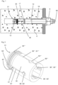
- the figures show an embodiment of an inventive expansion anchor.
- the expansion anchor comprises an elongate anchor bolt 10 defining a longitudinal axis 99, an expansion sleeve 30, which surrounds the anchor bolt 10, and a wedge body 12 provided on the anchor bolt 10, namely in the vicinity of the front end of the anchor bolt 10.
- the wedge body 12 is designed for wedging the expansion sleeve 30 radially outwardly when the wedge body 12 is drawn into the expansion sleeve 30 in the rearwards direction, i.e. in the pull-out direction.
- the lateral surface of the wedge body 12 converges rearwardly, at least regionally.
- the longitudinal axis 99 extends through the front end and through the rear end of the anchor bolt 10.
- the anchor bolt 10 has a neck, which is located adjacent to and rearwards of the wedge body 12.
- the expansion sleeve 30 at least partly surrounds this neck, at least before installation of the anchor.
- the diameter of the anchor bolt 10 can be minimal.
- the expansion anchor is a stud type anchor.
- the anchor bolt 10 has, at the rearward end of the neck, a shoulder 17 facing forwards for axially engaging the expansion sleeve 30 and for advancing the expansion sleeve 30 forwards.
- the wedge body 12 is, by way of example, integral with the remainder of the anchor bolt 10, but in alternative embodiments, the anchor bolt 10 can consist of several separate parts.
- the anchor bolt 10 is provided with a tension-introducing structure 18, which is here, by way of example, an external thread provided on the anchor bolt 10.
- a tension-introducing structure 18 which is here, by way of example, an external thread provided on the anchor bolt 10.
- this is an example only, and other structures such as internal threads, bayonet mechanisms or heads can also be envisaged.
- the expansion sleeve 30 is a C-shaped clip and is provided with a plurality of expansion slits 36', 36", 36′′′, 36 ⁇ .
- Each of these expansion slits 36', 36", 36′′′, 36 ⁇ originates at the front face 31 of the expansion sleeve 30 (i.e. at that face of the expansion sleeve 30 that faces the wedge body 12) and extends towards the rear end of the expansion sleeve 30 (and thus towards the rear end of the anchor bolt 10).
- Each of the expansion slits 36', 36", 36′′′, 36 ⁇ radially cuts through the expansion sleeve 30, i.e. each of the expansion slits 36', 36", 36′′′, 36 ⁇ divides the expansion sleeve 30.
- the expansion slit 36' comprises a mouth 64', a stem 61' that adjoins the mouth 64' and a head 63' that adjoins the stem 61'.
- the mouth 64' is arranged at the front face 31 of the expansion sleeve 30 and forwardly with respect to the stem 61', whereas the head 63' is arranged rearwardly with respect to the stem 61'. Accordingly, the stem 61' is arranged between the head 63' and the mouth 64'.
- the mouth 64' forms the forward end of the expansion slit 36' and the head 63' forms the rearward end of the expansion slit 36'.
- the stem 61' is a narrow, generally linear trench.
- the head 63' Compared to the stem 61', the head 63' has greater width in the circumferential direction, i.e. around the longitudinal axis 99. Due to its width, the head 63' forms a local weakening of the adjacent expansion sleeve 30, which facilitates expansion of the expansion sleeve 30.
- the mouth 64' forms a delta structure that converges into the stem 61'. The delta structure provides a rounding of the front face 31.
- the stem 61' extends, generally, in the axial direction, i.e. generally parallel to the longitudinal axis 99.
- angled configurations could also be envisaged.
- the head 63' is generally circular. This, however, is only an example, and other, non-circular outlines can also be envisaged. In particular, an elongate, for example approximately elliptical, outline, wherein the elongate direction generally follows the circumferential direction of the anchor bolt 10 can be provided.
- the stem 61' is delimited by a first flank 41' of the expansion sleeve 30, and by a second flank 42' of the expansion sleeve 30, wherein the first flank 41' and the second flank 42' face each other.
- Both the first flank 41' and the second flank 42' are generally free form shaped when in the axial direction.
- the first flank 41' and the second flank 42' extend non-parallel with respect to one another.
- Both the first flank 41' and the second flank 42' are non-planar each.
- the stem 61' Due to the non-planar shape of the first flank 41' and the second flank 42', the stem 61' has a widening 43' (at which the width of the expansion slit 36' is a local maximum, in particular a strict local maximum) and a narrowing 44' (at which the width of the expansion slit 36' is a local minimum, in particular a strict local maximum, wherein in both cases, the width can in particular be measured in the circumferential direction).
- Expansion slit 36" also comprises a mouth, a stem and a head 63", wherein these items are arranged and configured in analogy to expansion slit 36', so that the description above is applicable mutatis mutandis.
- Expansion slit 36′′′ also comprises a mouth, a stem and a head 63′′′, wherein these items are arranged and configured in analogy to expansion slit 36', so that the description above is applicable mutatis mutandis.
- Expansion slit 36 ⁇ also comprises a mouth 64 ⁇ , a stem 61 ⁇ and a head 63"", wherein these items are arranged and configured in analogy to expansion slit 36', so that the description above is applicable mutatis mutandis.
- the expansion slits 36', 36", 36′′′ are blind slits each, and accordingly, they do not reach the rear end of the expansion sleeve 30. Accordingly, the head 63' defines a rear end of expansion slit 36', the head 63" defines a rear end of expansion slit 36" and the head 63′′′ defines a rear end of expansion slit 36′′′.
- the expansion slit 36" is a through slit which extends all the way through the expansion sleeve 30, i.e. from the front face 31 of the expansion sleeve 30 to the rear end of the expansion sleeve 30.
- the expansion slit 36 ⁇ has a tail 69 ⁇ , which extends from the head 63 ⁇ to the rear end of the expansion sleeve 30.
- the head 63 ⁇ is thus located axially between the stem 61 ⁇ and the tail 69"".
- the expansion slit 36 ⁇ being a through slit can be interrelated to a manufacturing process in which a flat blank is bent around the anchor bolt 10 to give the expansion sleeve 30, so that the expansion slit 36 ⁇ gives the closure interface of the expansion sleeve 30.
- the expansion sleeve 30 has non-constant wall-thickness, i.e. the wall thickness is dependent on the position on the expansion sleeve 30, in particular on the circumferential position.
- the expansion anchor is introduced, front end first, into a hole in a substrate 6. Subsequently, the wedge body 12 is drawn into the front face 31 of the expansion sleeve 30. In the present embodiment, this is achieved by pulling the anchor bolt 10 together with the wedge body 12 rearwardly, in particular by tightening a nut 8 provided on the tension-introducing structure 18 of the anchor bolt 10. This loads the expansion sleeve 30 radially outwardly, thereby locking the expansion anchor in the substrate.
Landscapes
- Engineering & Computer Science (AREA)
- General Engineering & Computer Science (AREA)
- Mechanical Engineering (AREA)
- Dowels (AREA)
- Joining Of Building Structures In Genera (AREA)
Claims (2)
- Spreizanker, der aufweist- einen Ankerbolzen (10),- eine Spreizhülse (30), die den Ankerbolzen (10) umgibt, und- einen Keilkörper (12), der sich zum Verkeilen der Spreizhülse (30) in einem vorderen Bereich des Ankerbolzens (10) befindet, wobei die Spreizhülse (30) eine dem Keilkörper (12) zugewandte Stirnfläche (31) aufweist,- wobei mindestens ein Spreizschlitz (36) innerhalb der Spreizhülse (30) bereitgestellt ist, wobei der Spreizschlitz (36) von der Stirnfläche (31) der Spreizhülse (30) ausgeht, wobei der Spreizschlitz (36) eine Mündung (64), die sich benachbart zu der Stirnfläche (31) befindet, einen Schaft (61), der an die Mündung (64) anschließt, und einen Kopf (63), der an den Schaft (61) anschließt, aufweist, wobei der Kopf (63) breiter ist als der Schaft (61), und wobei der Schaft (61) sich zwischen dem Kopf (63) und der Mündung (64) befindet,- wobei der Schaft (61) des Spreizschlitzes (36) durch eine erste Flanke (41) der Spreizhülse (30) und durch eine zweite Flanke (42) der Spreizhülse (30) begrenzt wird, dadurch gekennzeichnet, dass- die erste Flanke (41) und die zweite Flanke (42) beide durchgehend nicht planar sind, sodass entlang des Schafts (61) mindestens eine Verbreiterung (43) und mindestens eine Verengung (44) gebildet werden.
- Spreizanker nach Anspruch 1,
dadurch gekennzeichnet, dass
die erste Flanke (41) und die zweite Flanke (42) durchgehend nicht planparallel in Bezug zueinander sind.
Applications Claiming Priority (2)
| Application Number | Priority Date | Filing Date | Title |
|---|---|---|---|
| EP21168041.8A EP4074991A1 (de) | 2021-04-13 | 2021-04-13 | Spreizdübel |
| PCT/EP2022/059176 WO2022218787A1 (en) | 2021-04-13 | 2022-04-07 | Expansion anchor |
Publications (3)
| Publication Number | Publication Date |
|---|---|
| EP4323657A1 EP4323657A1 (de) | 2024-02-21 |
| EP4323657B1 true EP4323657B1 (de) | 2025-02-26 |
| EP4323657C0 EP4323657C0 (de) | 2025-02-26 |
Family
ID=75497848
Family Applications (2)
| Application Number | Title | Priority Date | Filing Date |
|---|---|---|---|
| EP21168041.8A Withdrawn EP4074991A1 (de) | 2021-04-13 | 2021-04-13 | Spreizdübel |
| EP22720725.5A Active EP4323657B1 (de) | 2021-04-13 | 2022-04-07 | Spreizdübel |
Family Applications Before (1)
| Application Number | Title | Priority Date | Filing Date |
|---|---|---|---|
| EP21168041.8A Withdrawn EP4074991A1 (de) | 2021-04-13 | 2021-04-13 | Spreizdübel |
Country Status (5)
| Country | Link |
|---|---|
| US (1) | US20240183377A1 (de) |
| EP (2) | EP4074991A1 (de) |
| CN (1) | CN116917631A (de) |
| ES (1) | ES3014102T3 (de) |
| WO (1) | WO2022218787A1 (de) |
Families Citing this family (2)
| Publication number | Priority date | Publication date | Assignee | Title |
|---|---|---|---|---|
| PL445191A1 (pl) * | 2023-06-12 | 2024-12-16 | Koelner Rawlplug Ip Spółka Z Ograniczoną Odpowiedzialnością | Rozporowa kotwa |
| EP4560152A1 (de) | 2023-11-21 | 2025-05-28 | Hilti Aktiengesellschaft | Spreizanker mit abgewinkelter stützwandübergangskante |
Family Cites Families (17)
| Publication number | Priority date | Publication date | Assignee | Title |
|---|---|---|---|---|
| US2762119A (en) * | 1953-04-22 | 1956-09-11 | John E Jackson | Method of making a bolt anchor shield |
| CH661569A5 (en) * | 1983-08-09 | 1987-07-31 | Egli Fischer & Co | Anchor screw |
| DE4219984A1 (de) * | 1992-06-19 | 1993-12-23 | Fischer Artur Werke Gmbh | Spreizanker |
| DE4324244A1 (de) * | 1992-11-26 | 1994-06-01 | Fischer Artur Werke Gmbh | Spreizanker aus Metall sowie Verfahren zu dessen Herstellung |
| DE19530782C2 (de) * | 1995-08-22 | 1998-03-26 | Raymond A Gmbh & Co Kg | Metallblechdübel |
| DE19541564A1 (de) * | 1995-11-08 | 1997-05-15 | Fischer Artur Werke Gmbh | Metallspreizanker |
| CA2265264C (en) * | 1998-03-16 | 2003-09-09 | Societe De Prospection Et D'inventions Techniques Spit | Anchor bolt with an expansion core |
| US6309155B1 (en) * | 2000-06-29 | 2001-10-30 | Joker Industrial Co., Ltd. | Expanding sleeve anchor used in a concrete wall and structure for enhancing the anchoring capability thereof |
| US20020194718A1 (en) * | 2001-06-21 | 2002-12-26 | David Yekutiely | Anchoring system and methods therefor |
| PT1275860E (pt) * | 2001-07-12 | 2004-06-30 | Fischer Artur Werke Gmbh | Bucha expansivel para fixacao de materiais de construcao ocos ou macicos |
| DE102009045345A1 (de) * | 2009-10-06 | 2011-04-07 | Hilti Aktiengesellschaft | Spreizdübel |
| DE102011007570A1 (de) * | 2011-04-18 | 2012-10-18 | Hilti Aktiengesellschaft | Spreizdübel |
| EP2848825A1 (de) | 2013-09-16 | 2015-03-18 | HILTI Aktiengesellschaft | Spreizanker |
| USD804940S1 (en) * | 2016-07-25 | 2017-12-12 | Hilti Aktiengesellschaft | Helical sleeve of an anchor |
| DE102016123500A1 (de) * | 2016-12-05 | 2018-06-07 | Fischerwerke Gmbh & Co. Kg | Verfahren zum Setzen eines Ankers in einem Ankerloch in einem Ankergrund und Anker zum Setzen mit dem Verfahren |
| EP3477125A1 (de) | 2017-10-25 | 2019-05-01 | HILTI Aktiengesellschaft | Spreizdübel mit hülsenwiderlagerwänden |
| EP3584453A1 (de) * | 2018-06-20 | 2019-12-25 | HILTI Aktiengesellschaft | Spreizanker mit nichtachsensymmetrischer aussparung |
-
2021
- 2021-04-13 EP EP21168041.8A patent/EP4074991A1/de not_active Withdrawn
-
2022
- 2022-04-07 CN CN202280018958.6A patent/CN116917631A/zh active Pending
- 2022-04-07 ES ES22720725T patent/ES3014102T3/es active Active
- 2022-04-07 US US18/284,609 patent/US20240183377A1/en active Pending
- 2022-04-07 WO PCT/EP2022/059176 patent/WO2022218787A1/en not_active Ceased
- 2022-04-07 EP EP22720725.5A patent/EP4323657B1/de active Active
Also Published As
| Publication number | Publication date |
|---|---|
| CN116917631A (zh) | 2023-10-20 |
| ES3014102T3 (en) | 2025-04-16 |
| EP4323657A1 (de) | 2024-02-21 |
| US20240183377A1 (en) | 2024-06-06 |
| EP4323657C0 (de) | 2025-02-26 |
| EP4074991A1 (de) | 2022-10-19 |
| WO2022218787A1 (en) | 2022-10-20 |
Similar Documents
| Publication | Publication Date | Title |
|---|---|---|
| EP2337959B1 (de) | Blindniet | |
| EP4323657B1 (de) | Spreizdübel | |
| KR102715974B1 (ko) | 비축대칭 리세스를 갖는 확장 앵커 | |
| EP3701155B1 (de) | Spreizdübel mit hülsenwiderlagerwänden | |
| EP4323656B1 (de) | Spreizdübel | |
| HK40100177A (en) | Expansion anchor | |
| HK40100177B (en) | Expansion anchor | |
| EP3864304B1 (de) | Spreizanker mit gerilltem ankerbolzen | |
| EP3864305B1 (de) | Spreizdübel mit vorwärts- und rückwärtsrillen | |
| EP3864306B1 (de) | Spreizdübel mit vorgewölbter zone | |
| HK40101733A (en) | Expansion anchor | |
| HK40101733B (en) | Expansion anchor | |
| CN121941854A (zh) | 具有成角度的抵接壁过渡边缘的膨胀锚 | |
| EP4560152A1 (de) | Spreizanker mit abgewinkelter stützwandübergangskante | |
| HK40040508B (en) | Expansion anchor with a nonaxisymmetric recess | |
| HK40040508A (en) | Expansion anchor with a nonaxisymmetric recess | |
| HK40026619A (en) | Expansion anchor with sleeve abutment walls |
Legal Events
| Date | Code | Title | Description |
|---|---|---|---|
| STAA | Information on the status of an ep patent application or granted ep patent |
Free format text: STATUS: UNKNOWN |
|
| STAA | Information on the status of an ep patent application or granted ep patent |
Free format text: STATUS: THE INTERNATIONAL PUBLICATION HAS BEEN MADE |
|
| PUAI | Public reference made under article 153(3) epc to a published international application that has entered the european phase |
Free format text: ORIGINAL CODE: 0009012 |
|
| STAA | Information on the status of an ep patent application or granted ep patent |
Free format text: STATUS: REQUEST FOR EXAMINATION WAS MADE |
|
| 17P | Request for examination filed |
Effective date: 20231113 |
|
| AK | Designated contracting states |
Kind code of ref document: A1 Designated state(s): AL AT BE BG CH CY CZ DE DK EE ES FI FR GB GR HR HU IE IS IT LI LT LU LV MC MK MT NL NO PL PT RO RS SE SI SK SM TR |
|
| REG | Reference to a national code |
Ref country code: HK Ref legal event code: DE Ref document number: 40100177 Country of ref document: HK |
|
| DAV | Request for validation of the european patent (deleted) | ||
| DAX | Request for extension of the european patent (deleted) | ||
| GRAP | Despatch of communication of intention to grant a patent |
Free format text: ORIGINAL CODE: EPIDOSNIGR1 |
|
| STAA | Information on the status of an ep patent application or granted ep patent |
Free format text: STATUS: GRANT OF PATENT IS INTENDED |
|
| INTG | Intention to grant announced |
Effective date: 20241120 |
|
| GRAS | Grant fee paid |
Free format text: ORIGINAL CODE: EPIDOSNIGR3 |
|
| GRAA | (expected) grant |
Free format text: ORIGINAL CODE: 0009210 |
|
| STAA | Information on the status of an ep patent application or granted ep patent |
Free format text: STATUS: THE PATENT HAS BEEN GRANTED |
|
| AK | Designated contracting states |
Kind code of ref document: B1 Designated state(s): AL AT BE BG CH CY CZ DE DK EE ES FI FR GB GR HR HU IE IS IT LI LT LU LV MC MK MT NL NO PL PT RO RS SE SI SK SM TR |
|
| REG | Reference to a national code |
Ref country code: GB Ref legal event code: FG4D |
|
| REG | Reference to a national code |
Ref country code: CH Ref legal event code: EP |
|
| REG | Reference to a national code |
Ref country code: DE Ref legal event code: R096 Ref document number: 602022011167 Country of ref document: DE |
|
| REG | Reference to a national code |
Ref country code: IE Ref legal event code: FG4D |
|
| U01 | Request for unitary effect filed |
Effective date: 20250226 |
|
| U07 | Unitary effect registered |
Designated state(s): AT BE BG DE DK EE FI FR IT LT LU LV MT NL PT RO SE SI Effective date: 20250307 |
|
| REG | Reference to a national code |
Ref country code: ES Ref legal event code: FG2A Ref document number: 3014102 Country of ref document: ES Kind code of ref document: T3 Effective date: 20250416 |
|
| U20 | Renewal fee for the european patent with unitary effect paid |
Year of fee payment: 4 Effective date: 20250425 |
|
| PG25 | Lapsed in a contracting state [announced via postgrant information from national office to epo] |
Ref country code: RS Free format text: LAPSE BECAUSE OF FAILURE TO SUBMIT A TRANSLATION OF THE DESCRIPTION OR TO PAY THE FEE WITHIN THE PRESCRIBED TIME-LIMIT Effective date: 20250526 |
|
| PG25 | Lapsed in a contracting state [announced via postgrant information from national office to epo] |
Ref country code: PL Free format text: LAPSE BECAUSE OF FAILURE TO SUBMIT A TRANSLATION OF THE DESCRIPTION OR TO PAY THE FEE WITHIN THE PRESCRIBED TIME-LIMIT Effective date: 20250226 |
|
| PGFP | Annual fee paid to national office [announced via postgrant information from national office to epo] |
Ref country code: ES Payment date: 20250530 Year of fee payment: 4 |
|
| PG25 | Lapsed in a contracting state [announced via postgrant information from national office to epo] |
Ref country code: IS Free format text: LAPSE BECAUSE OF FAILURE TO SUBMIT A TRANSLATION OF THE DESCRIPTION OR TO PAY THE FEE WITHIN THE PRESCRIBED TIME-LIMIT Effective date: 20250626 Ref country code: NO Free format text: LAPSE BECAUSE OF FAILURE TO SUBMIT A TRANSLATION OF THE DESCRIPTION OR TO PAY THE FEE WITHIN THE PRESCRIBED TIME-LIMIT Effective date: 20250526 |
|
| PG25 | Lapsed in a contracting state [announced via postgrant information from national office to epo] |
Ref country code: HR Free format text: LAPSE BECAUSE OF FAILURE TO SUBMIT A TRANSLATION OF THE DESCRIPTION OR TO PAY THE FEE WITHIN THE PRESCRIBED TIME-LIMIT Effective date: 20250226 |
|
| PG25 | Lapsed in a contracting state [announced via postgrant information from national office to epo] |
Ref country code: GR Free format text: LAPSE BECAUSE OF FAILURE TO SUBMIT A TRANSLATION OF THE DESCRIPTION OR TO PAY THE FEE WITHIN THE PRESCRIBED TIME-LIMIT Effective date: 20250527 |
|
| PGFP | Annual fee paid to national office [announced via postgrant information from national office to epo] |
Ref country code: CH Payment date: 20250501 Year of fee payment: 4 |
|
| PG25 | Lapsed in a contracting state [announced via postgrant information from national office to epo] |
Ref country code: SM Free format text: LAPSE BECAUSE OF FAILURE TO SUBMIT A TRANSLATION OF THE DESCRIPTION OR TO PAY THE FEE WITHIN THE PRESCRIBED TIME-LIMIT Effective date: 20250226 |
|
| PG25 | Lapsed in a contracting state [announced via postgrant information from national office to epo] |
Ref country code: CZ Free format text: LAPSE BECAUSE OF FAILURE TO SUBMIT A TRANSLATION OF THE DESCRIPTION OR TO PAY THE FEE WITHIN THE PRESCRIBED TIME-LIMIT Effective date: 20250226 |
|
| PG25 | Lapsed in a contracting state [announced via postgrant information from national office to epo] |
Ref country code: SK Free format text: LAPSE BECAUSE OF FAILURE TO SUBMIT A TRANSLATION OF THE DESCRIPTION OR TO PAY THE FEE WITHIN THE PRESCRIBED TIME-LIMIT Effective date: 20250226 |
|
| PG25 | Lapsed in a contracting state [announced via postgrant information from national office to epo] |
Ref country code: MC Free format text: LAPSE BECAUSE OF FAILURE TO SUBMIT A TRANSLATION OF THE DESCRIPTION OR TO PAY THE FEE WITHIN THE PRESCRIBED TIME-LIMIT Effective date: 20250226 |
|
| PLBE | No opposition filed within time limit |
Free format text: ORIGINAL CODE: 0009261 |
|
| STAA | Information on the status of an ep patent application or granted ep patent |
Free format text: STATUS: NO OPPOSITION FILED WITHIN TIME LIMIT |
|
| 26N | No opposition filed |
Effective date: 20251127 |
|
| PG25 | Lapsed in a contracting state [announced via postgrant information from national office to epo] |
Ref country code: IE Free format text: LAPSE BECAUSE OF NON-PAYMENT OF DUE FEES Effective date: 20250407 |