EP4323680B1 - Fondations sous-marines - Google Patents
Fondations sous-marines Download PDFInfo
- Publication number
- EP4323680B1 EP4323680B1 EP22721957.3A EP22721957A EP4323680B1 EP 4323680 B1 EP4323680 B1 EP 4323680B1 EP 22721957 A EP22721957 A EP 22721957A EP 4323680 B1 EP4323680 B1 EP 4323680B1
- Authority
- EP
- European Patent Office
- Prior art keywords
- foundation
- seabed
- plate
- pipeline
- skirt
- Prior art date
- Legal status (The legal status is an assumption and is not a legal conclusion. Google has not performed a legal analysis and makes no representation as to the accuracy of the status listed.)
- Active
Links
Images


Classifications
-
- F—MECHANICAL ENGINEERING; LIGHTING; HEATING; WEAPONS; BLASTING
- F16—ENGINEERING ELEMENTS AND UNITS; GENERAL MEASURES FOR PRODUCING AND MAINTAINING EFFECTIVE FUNCTIONING OF MACHINES OR INSTALLATIONS; THERMAL INSULATION IN GENERAL
- F16L—PIPES; JOINTS OR FITTINGS FOR PIPES; SUPPORTS FOR PIPES, CABLES OR PROTECTIVE TUBING; MEANS FOR THERMAL INSULATION IN GENERAL
- F16L1/00—Laying or reclaiming pipes; Repairing or joining pipes on or under water
- F16L1/12—Laying or reclaiming pipes on or under water
- F16L1/20—Accessories therefor, e.g. floats or weights
-
- B—PERFORMING OPERATIONS; TRANSPORTING
- B63—SHIPS OR OTHER WATERBORNE VESSELS; RELATED EQUIPMENT
- B63B—SHIPS OR OTHER WATERBORNE VESSELS; EQUIPMENT FOR SHIPPING
- B63B21/00—Tying-up; Shifting, towing, or pushing equipment; Anchoring
- B63B21/24—Anchors
- B63B21/26—Anchors securing to bed
-
- E—FIXED CONSTRUCTIONS
- E02—HYDRAULIC ENGINEERING; FOUNDATIONS; SOIL SHIFTING
- E02B—HYDRAULIC ENGINEERING
- E02B17/00—Artificial islands mounted on piles or like supports, e.g. platforms on raisable legs or offshore constructions; Construction methods therefor
-
- E—FIXED CONSTRUCTIONS
- E02—HYDRAULIC ENGINEERING; FOUNDATIONS; SOIL SHIFTING
- E02D—FOUNDATIONS; EXCAVATIONS; EMBANKMENTS; UNDERGROUND OR UNDERWATER STRUCTURES
- E02D15/00—Handling building or like materials for hydraulic engineering or foundations
- E02D15/08—Sinking workpieces into water or soil inasmuch as not provided for elsewhere
-
- E—FIXED CONSTRUCTIONS
- E02—HYDRAULIC ENGINEERING; FOUNDATIONS; SOIL SHIFTING
- E02D—FOUNDATIONS; EXCAVATIONS; EMBANKMENTS; UNDERGROUND OR UNDERWATER STRUCTURES
- E02D27/00—Foundations as substructures
- E02D27/32—Foundations for special purposes
- E02D27/50—Anchored foundations
-
- E—FIXED CONSTRUCTIONS
- E02—HYDRAULIC ENGINEERING; FOUNDATIONS; SOIL SHIFTING
- E02D—FOUNDATIONS; EXCAVATIONS; EMBANKMENTS; UNDERGROUND OR UNDERWATER STRUCTURES
- E02D27/00—Foundations as substructures
- E02D27/32—Foundations for special purposes
- E02D27/52—Submerged foundations, i.e. submerged in open water
- E02D27/525—Submerged foundations, i.e. submerged in open water using elements penetrating the underwater ground
-
- F—MECHANICAL ENGINEERING; LIGHTING; HEATING; WEAPONS; BLASTING
- F16—ENGINEERING ELEMENTS AND UNITS; GENERAL MEASURES FOR PRODUCING AND MAINTAINING EFFECTIVE FUNCTIONING OF MACHINES OR INSTALLATIONS; THERMAL INSULATION IN GENERAL
- F16L—PIPES; JOINTS OR FITTINGS FOR PIPES; SUPPORTS FOR PIPES, CABLES OR PROTECTIVE TUBING; MEANS FOR THERMAL INSULATION IN GENERAL
- F16L1/00—Laying or reclaiming pipes; Repairing or joining pipes on or under water
- F16L1/12—Laying or reclaiming pipes on or under water
- F16L1/123—Devices for the protection of pipes under water
-
- F—MECHANICAL ENGINEERING; LIGHTING; HEATING; WEAPONS; BLASTING
- F16—ENGINEERING ELEMENTS AND UNITS; GENERAL MEASURES FOR PRODUCING AND MAINTAINING EFFECTIVE FUNCTIONING OF MACHINES OR INSTALLATIONS; THERMAL INSULATION IN GENERAL
- F16L—PIPES; JOINTS OR FITTINGS FOR PIPES; SUPPORTS FOR PIPES, CABLES OR PROTECTIVE TUBING; MEANS FOR THERMAL INSULATION IN GENERAL
- F16L1/00—Laying or reclaiming pipes; Repairing or joining pipes on or under water
- F16L1/12—Laying or reclaiming pipes on or under water
- F16L1/16—Laying or reclaiming pipes on or under water on the bottom
-
- F—MECHANICAL ENGINEERING; LIGHTING; HEATING; WEAPONS; BLASTING
- F16—ENGINEERING ELEMENTS AND UNITS; GENERAL MEASURES FOR PRODUCING AND MAINTAINING EFFECTIVE FUNCTIONING OF MACHINES OR INSTALLATIONS; THERMAL INSULATION IN GENERAL
- F16L—PIPES; JOINTS OR FITTINGS FOR PIPES; SUPPORTS FOR PIPES, CABLES OR PROTECTIVE TUBING; MEANS FOR THERMAL INSULATION IN GENERAL
- F16L1/00—Laying or reclaiming pipes; Repairing or joining pipes on or under water
- F16L1/12—Laying or reclaiming pipes on or under water
- F16L1/16—Laying or reclaiming pipes on or under water on the bottom
- F16L1/18—Laying or reclaiming pipes on or under water on the bottom the pipes being S- or J-shaped and under tension during laying
Definitions
- This invention relates to seabed foundations for resisting movement of subsea structures, such as pipelines used in the offshore oil and gas industry.
- Embodiments of the invention to be described, address the challenges of anchoring a subsea pipeline with improved resistance to movement but at a lower cost than previous solutions.
- Subsea pipelines must be held stable on the seabed both laterally and axially to avoid unplanned stresses and environmental risk.
- a subsea pipeline may require anchoring against axial movement during installation to allow a pipelay vessel to maintain tension in a pipeline catenary, especially when initiating the pipelay operation.
- a subsea pipeline may also require anchoring during its service life.
- a subsea pipeline is susceptible to move across the seabed over time after installation, especially down an incline if the seabed is sloped to any extent. Such movement may be driven by cycles of thermal elongation and contraction caused by temperature fluctuations between operation and shut-down, or by sea dynamics such as tidal currents or the effects of storms. Eventually, those influences can lead to an effect known as 'walking' of the pipeline laterally across the seabed away from its original position.
- One approach to mitigate buckling is to lay a pipeline along a sinuously-curved route or to incorporate expansion loops along the length of the pipeline at which the pipeline is relatively free to move relative to the seabed. Creating curves or loops in the pipeline layout absorbs damaging compressive forces and promotes the appearance of buckles in a controlled manner at selected locations.
- Another way of mitigating buckling is to anchor the pipeline to the seabed.
- the pipeline is anchored at its ends by end structures or terminal structures and/or at intervals along its length by inline structures such as a longitudinal series of hold-back clamps.
- pipeline motion may be restrained by anchoring the pipeline as disclosed in US 8882392 , in which anchor chains connect one or more hold-back clamps, attached to the exterior of the pipeline, to anchors embedded in the seabed.
- Other anchoring structures may be supported by a pile that is embedded, driven or grouted into the seabed or by a mudmat comprising a peripheral skirt embedded in the seabed.
- Suction piles are expensive to fabricate; also, installing the piles and their related links is a lengthy and complex process.
- seabed metrology may have to be performed after pile installation to determine the dimensions of rigid links to be fabricated and installed subsequently.
- heavy chains may require tensioning on the seabed to remove slack and to equalise tensile forces to prevent side-loading the pipeline.
- Shallow foundations such as mudmats are less expensive than suction piles to fabricate and are relatively simple to install and remove using a smaller installation vessel.
- shallow foundations are generally limited in terms of the reaction force they can provide.
- the load-restraining limitation of shallow foundations is largely due to weak seabed soil. As soil strength increases progressively below the mudline, the available soil reaction is highly dependent upon the depth of soil engagement.
- shallow foundation designs are limited to relatively shallow penetration into the seabed by their self-weight; also, limitations of fabrication and installation militate against extending the depth of their penetrating skirts.
- anchoring may be achieved by pinning the pipeline to the seabed soil using staple-like brackets as disclosed in US 4389034 or by connecting a collar around the pipeline to static foundations such as piles as proposed in GB 2081414 .
- staple-like fixings are insufficiently resistant to high loads, and arrangements of piles and collars are expensive to manufacture and to install as noted above. Installing anchors or piles in a sloping seabed can also be challenging.
- WO 2014/207560 to a sister company of the Applicant proposes installation of a mudmat foundation after pipelaying.
- a mudmat foundation structure straddling the pipeline is connected at the seabed to a pipeline accessory such as an in-line tee incorporated into the pipeline.
- a pipeline accessory such as an in-line tee incorporated into the pipeline.
- the primary purpose of the foundation structure is to support the weight of the accessory rather than to anchor the pipeline.
- skirts on the mudmat could be omitted, thus allowing the mudmat to slide across the seabed while still satisfying its primary purpose of supporting the weight of the accessory.
- KR 2019/0031868 describes the use of an inner partition wall in a suction bucket to improve the support force of a suction pile in order to address issues with seabed settlement after the suction pile is installed.
- GB 2511500 relates to a mudmat that is provided with stowable foundation elements that reduce the size of the mudmat when stowed but can be deployed to cover a greater area and lower the centre of gravity of the mudmat and any accessories fitted thereto in order to increase stability.
- US 5213444 discloses an apparatus for separating oil and/or gas leaking from an underwater oil well or transport system.
- the apparatus comprises a collector unit that floats on the surface of the sea and a downwardly extending skirt section to collect the leaking oil/gas.
- GB 2582271 describes the use of barb elements on a skirt of a subsea foundation embedded into the seabed, such as a suction pile.
- the barb elements aid penetration of the skirt into the seabed in a distal direction and then resist movement of the subsea foundation in an opposed proximal direction.
- US 6887016 discloses a mudmat foundation that comprises a plurality of legs that are pivotably connected to the mudmat. The legs pivot outwardly relative to the mudmat while being embedded in the seabed soil to enlarge the interior volume of the foundation, thereby increasing the load bearing capacity of the foundation.
- the invention provides a subsea foundation that comprises: at least one mudmat having a top panel and a skirt depending from the top panel to be embedded into seabed soil; and at least one auxiliary plate supported by the mudmat, the plate being deployable downwardly from a raised, retracted position in which the plate is held above a lower edge of the skirt into a lowered, deployed position in which the plate extends beneath the lower edge of the skirt to be embedded further into the seabed soil.
- the or each plate may extend parallel to a portion of the skirt and may be deployable along a path that extends parallel to the skirt.
- the or each plate may suitably be positioned between the top panel and the skirt, for example on an inboard side of the skirt or on an outboard side of the top panel. The or each plate could slide against the skirt during deployment.
- the or each plate may be arranged to free-fall from the retracted position into or toward the deployed position.
- the foundation could further comprise at least one ROV-operable latch that is arranged to hold the or each plate raised in the retracted position and that is operable to release the or each plate to drop into the deployed position.
- the foundation comprises a pair of these mudmats, mutually spaced about a central channel.
- the mudmats of the pair may be joined by a bridge structure that extends across the channel.
- the or each plate is suitably outboard of the bridge structure.
- the channel is preferably open-ended and open-bottomed.
- the foundation may further comprise a stab mechanism having at least one downwardly-extending leg that is deployable downwardly into the seabed soil.
- the stab mechanism may be aligned with or disposed in the channel between the mudmats of the pair. In that case, the stab mechanism may comprise a pair of parallel legs that are spaced apart in a lateral direction across the channel.
- the inventive concept embraces a subsea installation that comprises, in combination, an elongate subsea element such as a subsea pipeline, and a foundation of the invention co-operating with the elongate element to restrict movement of the elongate element across the seabed.
- the elongate element may comprise engagement formations that are co-operable with complementary formations of the foundation.
- the elongate element suitably extends along, and longitudinally beyond, the channel.
- the foundation has a stab mechanism comprising parallel legs, the elongate element may be received in a space between the legs.
- the inventive concept extends to a method of fixing a subsea foundation at a seabed location. That method comprises: lowering a foundation of the invention to the seabed location; embedding the skirt of the or each mudmat into soil of the seabed; and then deploying the or each plate into the deployed position, embedded deeper than the skirt into the soil of the seabed.
- the foundation may, for example, be used to restrict movement of an elongate subsea element, such as a subsea pipeline, across the seabed.
- the foundation may be landed on top of the elongate element previously laid on the seabed. More specifically, where the foundation comprises paired mudmats, the mudmats of the pair can be landed on mutually-opposed sides of the elongate element with the elongate element being received in the channel between them.
- Engagement formations of the elongate element may be engaged with complementary formations of the foundation, for example with legs of a stab mechanism of the foundation.
- the legs of the stab mechanism may suitably be deployed before deploying the or each plate of the foundation.
- the or each plate may be returned to the retracted position before moving the foundation to be fixed at a second seabed location.
- the foundation may be moved from the first seabed location to the second seabed location while remaining underwater.
- the first and second seabed locations could be spaced apart longitudinally along an elongate subsea element.
- the foundation could be used at the first seabed location to restrict movement of the elongate element when initiating laying of the elongate element. Then, the foundation could be used at the second seabed location to restrict movement of the elongate element after the elongate element has been laid on the seabed.
- the invention encompasses a system that greatly increases the capacity of shallow foundations by incorporating novel guillotine-type devices or end plates that are released subsea from a foundation structure after the structure is accurately located on a subsea pipeline. Upon release, free-fall dynamics assist the plates to embed deeply into the seabed soil, exceeding normal self-embedment limits.
- the foundation of the invention comprises a seabed structure that is modified with dynamically-released guillotine-type vertical plates, the plates preferably being guided for movement within the structure.
- a release mechanism is configured to retain the plates when raised, acting as a latching mechanism. Releasing the plates provides dynamic loading due to free-fall such that their momentum enhances their self-weight. Consequently, on being released to drop relative to the supporting structure, the blades aggressively penetrate seabed soil that would normally resist such penetration.
- the design objective is to engage the strength of the underlying soil to achieve increased resistance to movement.
- the additional bearing area of the deeply-embedded plates engages a large volume of the seabed soil to provide a firm foundation.
- the deeper soil naturally has greater consolidation providing increased resistance, further enhanced by the increased overburden weight of the overlying soil closer to the mudline.
- the load-bearing capacity of a shallow foundation can be increased greatly, potentially being at least doubled, to satisfy many of the pipeline restraint requirements presently encountered in the industry.
- the release mechanism maintains the plates level and vertical until released, for example by an ROV at the seabed, or by releasing supporting buoyancy subsea, or on command of personnel above water. Restraints or stop formations may limit the travel of the plates to a desired depth below the mudline to suit the application. Means may be provided to assist removal and re-installation of the foundation for re-use, such as a hydraulic or otherwise-powered drive acting on the plates or temporary addition of buoyancy to raise the plates to a retracted, latched position.
- a foundation of the invention can have dual capability. Specifically, when deployed to the seabed, the foundation can restrain axial movement of a pipeline or riser to sustain the tension required to control stress during installation. Afterwards, the foundation can be removed and reinstalled elsewhere over an installed pipeline to restrain movement of the pipeline axially and/or laterally.
- This dual capability reduces the number of seabed structures required to be deployed and can reduce installation time for redeployment because after being used for initiation, the foundation does not have to be brought back to the surface before being reinstalled over the installed pipeline.
- the foundation structure can be post-installed on a pipeline, which may be pre-equipped with a special clamp allowing axial movement of the pipeline to be restrained.
- Embodiments of the invention provide a pipeline anchoring structure comprising: an upper straddle to be installed on the pipeline; and a skirted foundation that comprises at least one vertical skirt plate embedded into the seabed.
- the foundation further comprises at least one vertically slidable plate, which may have a tapered bottom edge or tip.
- the slidable plate may be regarded as a self-embedding guillotine plate or blade.
- the principles of the invention can be applied to anchoring other elongate subsea elements such as the bottom of a riser, or another fluid conduit, or an umbilical, or a cable.
- the inventive concept can also embrace skirted mudmat-type foundations for other subsea applications.
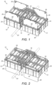
- a subsea foundation 10 comprises a pair of mudmats 12 that are spaced laterally apart from each other by, and are symmetrical about, an elongate central longitudinal slot or channel 14.
- the mudmats 12 are joined together rigidly by a bridge structure 16 that surmounts and crosses laterally over the channel 14.
- Each mudmat 12 comprises a horizontal top panel 18 that is surrounded by a peripheral side wall or skirt 20.
- the mudmats 12 are rectangular in plan view, such that mutually-orthogonal portions of the skirt 20 depend respectively from each laterally-facing side and each longitudinally-facing end of each top panel 18.
- the mudmats 12 are also mutually parallel about the channel 14, such that the laterally-facing side portions of the skirts 20 in mutual opposition about the channel 14 define straight parallel sides of the channel 14.
- the channel 14 is open-ended and open-bottomed to accommodate a subsea pipeline 22 that extends along, and extends longitudinally beyond, the channel 14. In this way, the mudmats 14 disposed to both sides of the channel 14 restrict lateral movement of the pipeline 22. As will be explained later in relation to the second embodiment shown in Figures 3 to 6 , further features may be provided to effect longitudinal, axial location of the pipeline 22 relative to the foundation 10.
- the pipeline 22 rests on the seabed 24, the mudline level of which is represented here by a dashed line. It will be apparent that the skirts 20 of the mudmats 12 are partially embedded in the soft soil of the seabed 24 by virtue of the self-weight of the foundation 10.
- the mudmats 12 of the foundation 10 are equipped with blade-like auxiliary guillotine plates 26 that lie in respective vertical planes and that are movable vertically, in those planes, relative to the top panels 18 and the skirts 20 of the mudmats 12.
- the plates 26 can be dropped from the raised, retracted position shown in Figure 1 to the lowered, deployed position shown in Figure 2 while remaining parallel to the adjacent portions of the skirts 20.
- the plates 26 are held above the bottom edge of the skirt 20.
- the plates 26 In the deployed position, the plates 26 extend beneath the bottom edge of the skirt 20, hence embedding deeper than the skirt 20 into the soil of the seabed 24. This greatly increases resistance to movement of the foundation 10 relative to the seabed 24, and so increases the load-bearing capacity of the foundation 10.
- the plates 26 drop quickly from the retracted position into the deployed position under their self-weight, hence impacting the seabed 24 with considerable kinetic energy to embed themselves substantially more deeply than the skirts 20.
- each mudmat 12 has a pair of parallel plates 26, adjacent to and parallel to end portions of the skirt 20.
- Each plate 26 lies in, and moves vertically through, a respective slot 28 defined immediately inboard of the skirt 20 and outboard of the top panel 18, hence being within the periphery of the mudmat 12 in plan view.
- the plates 26 can drop without hindrance from obstructions external to the foundation 10. Being also close to the skirt 20, the plates 26 more effectively engage soil of the seabed 24 that has already been disrupted and compacted by the skirt 20.
- Each plate 26 also lies longitudinally outboard of the bridge structure 16. This avoids restricting the size and shape of the bridge structure 16 which, as shown, can extend laterally beyond the laterally-inboard edges of the plates 26 opposed across the channel 14.
- Figures 1 and 2 show the option of stop formations 30 that limit embedment of the plates 26 into the soil of the seabed 24 and that then resist upward movement of the top panels 18 and skirts 20 of the mudmats 12 relative to the embedded plates 26.
- the stop formations 30 protrude from the plates 26 to bear against an upper surface of the top panel 18 and/or an upper edge of the skirt 20 to each side of the slots 28.
- FIG. 3 shows that the pipeline 22 may have engagement formations 34 that are co-operable with the foundation 10, those formations 34 being exemplified here by a flange, collar, clamp or other enlargement extending radially outwardly from the pipeline 22.
- Engagement of the formations 34 with the foundation 32 restricts axial movement of the pipeline 22 relative to the foundation 32 and may further restrict lateral movement of the pipeline 22 relative to the foundation 32.
- the foundation 32 has features for co-operating with the engagement formations 34 of the pipeline 22.
- Those co-operating features are defined here by a stab mechanism 36 that is supported by the bridge structure 16 above the channel 14 extending between the mudmats 12.
- the stab mechanism 36 is arranged to pin the foundation 32 to the seabed 24 and to engage the foundation 32 with the pipeline 22.
- the stab mechanism 36 comprises a vertically-movable fork 38 comprising a pair of parallel vertical prongs or legs 40.
- the legs 40 of the fork 38 slide within respective parallel rails 42 that extend vertically within the channel 14, lying against the mutually-opposed side portions of the skirts 20 that define the channel 14 between them.
- the legs 40 and their rails 42 are spaced apart laterally to an extent required to accommodate the pipeline 22 between them.
- the fork 38 can be lowered from a raised, retracted position shown in Figure 4 to a lowered, deployed position shown in Figures 5 and 6 .
- Retractable or removable pins 44 on the bridge structure 16 engage the fork 38 to lock the fork 38 in the retracted and deployed positions.
- the fork 38 can drop along the rails 42 under gravity from the retracted position when the pins 44 are released, penetrating the soil of the seabed 24 by virtue of self-weight and momentum.
- the legs 40 of the fork 38 are of different lengths and have tapered bottom ends.
- the foundation 32 is landed on the seabed 24 with the mudmats 12 straddling the pipeline 22.
- the pipeline 22 is therefore accommodated in the channel 14 between the mudmats 12.
- the rails 42 that accommodate the legs 40 of the fork 38 have bottom ends that splay outwardly in the downward direction. This shaping guides the foundation 32 around the pipeline 22 by guiding the pipeline 32 into the channel 14 as the foundation 32 is lowered.
- the rails 42 then embrace the pipeline 22 between them in the channel 14 as the skirts 20 of the mudmats 12 embed into the soil of the seabed 24. As shown in Figure 3 , the rails 42 may also co-operate with engagement formations 34 of the pipeline 22 to restrain axial movement of the pipeline 22 relative to the foundation 32.
- the plates 26 and the fork 38 are raised in their retracted positions.
- the fork 38 is released to fall into the deployed position, where the fork 38 straddles the pipeline 22 with the legs 40 to respective sides.
- the plates 26 are released to fall into their deployed positions in the manner of the first embodiment as shown in Figure 2 .
- the fork 38 ensures that the pipeline 22 is centrally disposed within the channel 14 to provide clearance for the plates 26 to be dropped without damaging the pipeline 22.
- the legs 40 of the fork 38 also protect the pipeline 22 from damage from the falling plates 26.
- FIGS 3 to 6 also show ROV-operable latches 46 mounted on the top panels 18 of the mudmats 12.
- Each plate 26 is co-operable with a respective one of the latches 46.
- the latches 46 engage in apertures 48 in the plates 26 to lock the plates 26 in their retracted and deployed positions and then are disengaged from the apertures 48 to release the plates 26 for movement between those positions.
- Each plate 26 therefore has two apertures 48, one above the other, the appropriate aperture 48 being brought into alignment with the latch 46 when the plate 26 is in its retracted or deployed position.
- FIGS 7 and 8a to 8c show a foundation 32 of the invention in two modes of use. This demonstrates that the same foundation 10 can be re-deployed at different subsea locations and potentially for different anchoring purposes, either on the same pipeline 22 or on a different pipeline.
- the foundation 32 is shown engaged with the seabed 24 while straddling and anchoring a trailing end of a pipeline 22 being laid on the seabed 24.
- the pipeline 22 hangs as a catenary from an installation vessel 50 on the surface 52.
- the foundation 32 is shown here with its plates 26 deployed and embedded in the seabed 24 more deeply than its mudmats 12. This enables the shallow foundation 32 to provide improved axial location for the pipeline 22. In this way, the foundation 32 allows the installation vessel 50 to generate desired tension in the catenary of the pipeline 22 that hangs between the surface 52 and the seabed 24, without requiring more expensive and complex pile foundations.
- the foundation 32 When a sufficient length of the pipeline 22 has been laid on the seabed 24, the foundation 32 is no longer required to react against tension applied to the catenary by the installation vessel 50. Indeed, the foundation 32 can then be repurposed to anchor the installed pipeline 22 at a different intermediate location along its length. This is shown schematically in Figures 8a to 8c , where a support vessel 54 shown at the surface 52 is equipped with a winch 56 and a lifting line 58 to lift and move the foundation 32 as required.
- the foundation 32 is disengaged from the seabed 24 by lifting the plates 26 back to their retracted positions, for example by using the lifting line 58 or with the assistance of temporary buoyancy.
- the support vessel 54 then pulls the foundation 32, with the plates 26 retracted into the mudmats 12, clear of the seabed 24 and transports the foundation 32 to a new intermediate location along the pipeline 22, with the foundation 32 preferably remaining underwater throughout as shown in Figure 8a .
- the foundation 32 is lowered back onto the pipeline 22 at the desired location as shown in Figure 8b , partially embedding its mudmats 12 into the seabed 24.
- the plates 26 are released again to drop into their deployed positions, embedding deeper into the soil of the seabed 24 to relocate the foundation 32.
- An ROV 60 is shown supervising the operation and controlling release of the plates 26 using the latches 46 shown in Figures 3 to 6 .
- Each mudmat could have more or fewer guillotine plates, or such plates could be positioned differently with respect to each mudmat.
- plates could be provided on one, three or four sides of a rectangular mudmat, or plates could be provided additionally or alternatively on sides rather than ends of the mudmat.
- each guillotine plate need not be horizontal or straight.
- the bottom edge could instead be inclined, toothed, undulating, castellated or downwardly-tapered to ease penetration into the seabed soil.
- the engagement formations on the pipeline may be arranged to allow a limited range of movement of the pipeline relative to the foundation.
- longitudinally-spaced stops may delimit both ends of the range to resist bidirectional movement of the pipeline or single stops may limit unidirectional movement in either longitudinal direction.
Landscapes
- Engineering & Computer Science (AREA)
- General Engineering & Computer Science (AREA)
- Mechanical Engineering (AREA)
- Structural Engineering (AREA)
- Civil Engineering (AREA)
- Paleontology (AREA)
- Life Sciences & Earth Sciences (AREA)
- General Life Sciences & Earth Sciences (AREA)
- Mining & Mineral Resources (AREA)
- Combustion & Propulsion (AREA)
- Ocean & Marine Engineering (AREA)
- Chemical & Material Sciences (AREA)
- Earth Drilling (AREA)
- Underground Or Underwater Handling Of Building Materials (AREA)
- Physical Or Chemical Processes And Apparatus (AREA)
- Foundations (AREA)
Claims (31)
- Fondation sous-marine (10), comprenant :au moins un patin (12) comportant un panneau supérieur (18) et une jupe (20) s'étendant vers le bas à partir du panneau supérieur (18), destinée à être implantée dans le sol du fond marin ; etau moins une plaque auxiliaire (26) supportée par le patin (12), la plaque (26) étant déployable vers le bas d'une position rétractée élevée, dans laquelle la plaque (26) est maintenue au-dessus d'un bord inférieur de la jupe (20), jusqu'à une position déployée abaissée, dans laquelle la plaque (26) s'étend sous le bord inférieur de la jupe (20), pour être implantée plus profondément dans le sol du fond marin.
- Fondation (10) selon la revendication 1, dans laquelle la ou chaque plaque (26) s'étend parallèlement à une partie de la jupe (20).
- Fondation (10) selon la revendication 1 ou la revendication 2, dans laquelle la ou chaque plaque (26) est déployable le long d'un chemin qui s'étend parallèlement à la jupe (20).
- Fondation (10) selon l'une quelconque des revendications précédentes, dans laquelle la ou chaque plaque (26) est placée entre le panneau supérieur (18) et la jupe (20).
- Fondation (10) selon l'une quelconque des revendications précédentes, dans laquelle la ou chaque plaque (26) se trouve sur un côté intérieur de la jupe (20).
- Fondation (10) selon l'une quelconque des revendications précédentes, dans laquelle la ou chaque plaque (26) glisse contre la jupe (20) lors du déploiement.
- Fondation (10) selon l'une quelconque des revendications précédentes, dans laquelle la ou chaque plaque (26) se trouve sur un côté extérieur du panneau supérieur (18).
- Fondation (10) selon l'une quelconque des revendications précédentes, dans laquelle la ou chaque plaque (26) est conçue pour descendre par gravité de la position rétractée jusqu'à la position déployée.
- Fondation (10) selon l'une quelconque des revendications précédentes, comprenant, en outre, au moins un verrou manœuvrable par VTG (46) qui est conçu pour maintenir la ou chaque plaque (26) élevée dans la position rétractée et qui est manœuvrable pour libérer la ou chaque plaque (26) de façon à ce qu'elle descende jusqu'à la position déployée.
- Fondation (10) selon l'une quelconque des revendications précédentes, comprenant une paire desdits patins (12) qui sont mutuellement espacés autour d'un canal central (14).
- Fondation (10) selon la revendication 10, dans laquelle le canal (14) est un canal à extrémités ouvertes et à fond ouvert.
- Fondation (10) selon la revendication 10 ou la revendication 11, dans laquelle les patins (12) de la paire sont raccordés par une structure de pont (16) qui enjambe le canal (14).
- Fondation (10) selon la revendication 12, dans laquelle la ou chaque plaque (26) se trouve du côté extérieur de la structure de pont (16).
- Fondation (10) selon l'une quelconque des revendications précédentes, comprenant, en outre, un mécanisme d'ancrage (36) comportant au moins une patte s'étendant vers le bas (40) qui est déployable vers le bas dans le sol du fond marin.
- Fondation (10) selon la revendication 14 lorsqu'elle dépend de l'une quelconque des revendications 10 à 13, dans laquelle le mécanisme d'ancrage (36) est aligné avec ou disposé dans le canal (14) entre les patins (12) de la paire.
- Fondation (10) selon la revendication 15, dans laquelle le mécanisme d'ancrage (36) comprend une paire de pattes parallèles (40) qui sont espacées l'une de l'autre dans une direction latérale en travers du canal (14).
- Installation sous-marine comprenant, en combinaison, un élément sous-marin allongé (22) tel qu'une canalisation sous-marine, et la fondation (10) selon l'une quelconque des revendications précédentes coopérant avec l'élément allongé (22) pour limiter un déplacement de l'élément allongé (22) sur le fond marin.
- Installation selon la revendication 17, dans laquelle l'élément allongé (22) comprend des formations de mise en prise (34) propres à coopérer avec des formations complémentaires de la fondation (10).
- Installation selon la revendication 17 ou la revendication 18, dans laquelle la fondation (10) est telle que définie dans l'une quelconque des revendications 10 à 13 et l'élément allongé (22) s'étend le long, et longitudinalement au-delà, du canal (14) entre les patins (12) de la paire.
- Installation selon l'une quelconque des revendications 17 à 19, dans laquelle la fondation (10) est telle que définie dans la revendication 16 et l'élément allongé (22) est reçu dans l'espace entre les pattes (40) du mécanisme d'ancrage (36).
- Procédé de fixation d'une fondation sous-marine (10) à un emplacement sur le fond marin, le procédé comprenant :abaisser la fondation (10) selon l'une quelconque des revendications 1 à 16 jusqu'à l'emplacement sur le fond marin ;implanter la jupe (20) du ou de chaque patin (12) dans le sol du fond marin ; etdéployer la ou chaque plaque (26) jusqu'à la position déployée, implantée plus profondément que la jupe (20) dans le sol du fond marin.
- Procédé selon la revendication 21, comprenant l'utilisation de la fondation (10) pour limiter un déplacement d'un élément allongé sous-marin (22), tel qu'une canalisation sous-marine, sur le fond marin.
- Procédé selon la revendication 22, comprenant la pose de la fondation (10) au-dessus de l'élément allongé (22) précédemment mis en place sur le fond marin.
- Procédé selon la revendication 23, dans lequel la fondation (10) est telle que définie dans l'une quelconque des revendications 10 à 13 et les patins (12) de la paire sont posés sur des côtés mutuellement opposés de l'élément allongé (22), l'élément allongé (22) étant reçu dans le canal (14) entre eux.
- Procédé selon l'une quelconque des revendications 22 à 24, comprenant la mise en prise de formations de mise en prise (34) de l'élément allongé (22) avec des formations complémentaires de la fondation (10).
- Procédé selon la revendication 25, dans lequel la fondation (10) est telle que définie dans la revendication 16 et les formations complémentaires de la fondation (10) sont définies par les pattes (40) du mécanisme d'ancrage (36).
- Procédé selon la revendication 26, comprenant le déploiement des pattes (40) du mécanisme d'ancrage (36) avant le déploiement de la ou chaque plaque (26) de la fondation (10).
- Procédé selon l'une quelconque des revendications 21 à 27, comprenant : fixer la fondation (10) à un premier emplacement sur le fond marin ; ramener la ou chaque plaque (26) à la position rétractée ; et déplacer la fondation (10) pour la fixer à un second emplacement sur le fond marin.
- Procédé selon la revendication 28, comprenant le déplacement de la fondation (10) du premier emplacement sur le fond marin au second emplacement sur le fond marin alors que la fondation (10) reste sous l'eau.
- Procédé selon la revendication 28 ou la revendication 29, dans lequel les premier et second emplacements sur le fond marin sont espacés l'un de l'autre longitudinalement le long d'un élément allongé sous-marin (22).
- Procédé selon la revendication 30, comprenant l'utilisation de la fondation (10) au premier emplacement sur le fond marin pour limiter un déplacement de l'élément allongé (22) lorsque la mise en place de l'élément allongé (22) commence, et l'utilisation de la fondation (10) au second emplacement sur le fond marin pour limiter un déplacement de l'élément allongé (22) une fois que l'élément allongé (22) a été mis en place sur le fond marin.
Applications Claiming Priority (2)
| Application Number | Priority Date | Filing Date | Title |
|---|---|---|---|
| GB2105317.8A GB2605815B (en) | 2021-04-14 | 2021-04-14 | Seabed foundations |
| PCT/US2022/024642 WO2022221422A1 (fr) | 2021-04-14 | 2022-04-13 | Fondations sous-marines |
Publications (2)
| Publication Number | Publication Date |
|---|---|
| EP4323680A1 EP4323680A1 (fr) | 2024-02-21 |
| EP4323680B1 true EP4323680B1 (fr) | 2025-03-19 |
Family
ID=75949656
Family Applications (1)
| Application Number | Title | Priority Date | Filing Date |
|---|---|---|---|
| EP22721957.3A Active EP4323680B1 (fr) | 2021-04-14 | 2022-04-13 | Fondations sous-marines |
Country Status (6)
| Country | Link |
|---|---|
| US (1) | US12252858B2 (fr) |
| EP (1) | EP4323680B1 (fr) |
| AU (1) | AU2022256994B2 (fr) |
| BR (1) | BR112023020884A2 (fr) |
| GB (1) | GB2605815B (fr) |
| WO (1) | WO2022221422A1 (fr) |
Families Citing this family (3)
| Publication number | Priority date | Publication date | Assignee | Title |
|---|---|---|---|---|
| NL2023942B1 (en) * | 2019-10-02 | 2021-06-11 | Spt Equipment Bv | Eccentric suction pile pump with hinged lift appliance. |
| GB2630644B (en) | 2023-06-02 | 2025-10-08 | Subsea 7 Norway As | Protecting subsea structures |
| CN117313571B (zh) * | 2023-08-28 | 2026-02-06 | 上海交通大学 | 一种极端风暴潮作用下浅基础与黏土海床界面破坏时间的简易计算方法 |
Family Cites Families (15)
| Publication number | Priority date | Publication date | Assignee | Title |
|---|---|---|---|---|
| DK191180A (da) | 1979-05-23 | 1980-11-24 | Coyne & Bellier | Fremgangsmaade og arramgement til forankring af ledninger f eks pipe-line paa havbunden |
| US4389034A (en) | 1980-07-21 | 1983-06-21 | Anchoring International, Inc. | Underwater pipe anchoring device |
| GB2081414A (en) | 1980-08-08 | 1982-02-17 | Pilgrim Eng Dev | Pipe anchoring system |
| GB2224060A (en) * | 1988-10-22 | 1990-04-25 | Rothersaint Limited | Valve installation of a subsea pipeline |
| US5213444A (en) * | 1992-04-17 | 1993-05-25 | The United States Of America As Represented By The United States Department Of Energy | Oil/gas collector/separator for underwater oil leaks |
| FR2852662B1 (fr) | 2003-03-20 | 2005-06-03 | Procede d'installation d'armatures de precontrainte autour d'une conduite cylindrique enterree | |
| US6887016B1 (en) | 2003-10-15 | 2005-05-03 | Fmc Technologies, Inc. | Mudmat foundation for subsea equipment |
| US8702347B2 (en) | 2008-10-07 | 2014-04-22 | Chevron U.S.A. Inc. | Device for protecting a subsea structure and methods relating to same |
| US8882392B1 (en) | 2012-08-08 | 2014-11-11 | Pinnacle Engineering Inc. | Method and system for anchoring a pipeline at a subsea location |
| GB2511500B (en) * | 2013-03-04 | 2015-05-13 | Subsea 7 Ltd | Improvements relating to pipelaying |
| GB2515506B (en) | 2013-06-25 | 2015-11-25 | Acergy France SAS | Foundations for subsea pipeline accessories |
| KR102066144B1 (ko) * | 2017-09-18 | 2020-01-14 | 현대건설주식회사 | 내부 격벽을 이용한 석션버켓 및 이를 이용한 해양구조물 |
| GB2582271B (en) * | 2019-03-06 | 2022-04-20 | Subsea 7 Norway As | Embedded subsea foundations |
| US10781941B1 (en) | 2019-12-18 | 2020-09-22 | Trinity Bay Equipment Holdings, LLC | Pipeline retainer stake systems and methods |
| KR102168967B1 (ko) * | 2020-04-28 | 2020-10-22 | 한국해양과학기술원 | 석션파일 수직도 보정 장치 |
-
2021
- 2021-04-14 GB GB2105317.8A patent/GB2605815B/en active Active
-
2022
- 2022-04-13 US US18/286,792 patent/US12252858B2/en active Active
- 2022-04-13 BR BR112023020884A patent/BR112023020884A2/pt unknown
- 2022-04-13 WO PCT/US2022/024642 patent/WO2022221422A1/fr not_active Ceased
- 2022-04-13 AU AU2022256994A patent/AU2022256994B2/en active Active
- 2022-04-13 EP EP22721957.3A patent/EP4323680B1/fr active Active
Also Published As
| Publication number | Publication date |
|---|---|
| GB2605815B (en) | 2023-06-14 |
| EP4323680A1 (fr) | 2024-02-21 |
| US12252858B2 (en) | 2025-03-18 |
| GB2605815A (en) | 2022-10-19 |
| AU2022256994A1 (en) | 2023-10-26 |
| AU2022256994B2 (en) | 2026-05-07 |
| US20240191453A1 (en) | 2024-06-13 |
| WO2022221422A1 (fr) | 2022-10-20 |
| GB202105317D0 (en) | 2021-05-26 |
| BR112023020884A2 (pt) | 2023-12-12 |
Similar Documents
| Publication | Publication Date | Title |
|---|---|---|
| US12252858B2 (en) | Seabed foundations | |
| AU2017283742B2 (en) | Upgrading subsea foundations of mooring systems | |
| US6910831B2 (en) | Method for installing a pile anchor | |
| WO2004078576A2 (fr) | Systeme d'installation d'ancrage | |
| KR20190011716A (ko) | 해저 지지 유닛 및 천수 천공 터미널을 제공하는 방법 | |
| KR20130124457A (ko) | 해저 정박 시스템 및 방법 | |
| EP0058663B1 (fr) | Procede et appareil a tube en j pour canalisations | |
| EP2726767A2 (fr) | Mise en chantier de pipelines et ombilicaux souples légers | |
| AU2014300717A1 (en) | Foundations for subsea pipeline accessories | |
| EP3631266B1 (fr) | Procédé et système de pose d'une canalisation sous-marine | |
| WO2011033267A2 (fr) | Procédé de formation et d'installation d'un système à tube en j | |
| EP2989258B1 (fr) | Procédé d'installation de pieux dans un fond marin | |
| EP2014546A1 (fr) | Procédé d'installation d'une structure off-shore en mer | |
| JP2025511427A (ja) | 垂直柱アセンブリを備えた洋上プラットフォーム | |
| GB2493935A (en) | Buoyant structure with rapidly releasable seabed fixing arrangement | |
| GB2562977B (en) | Upgrading subsea foundations of mooring systems | |
| EP4103463B1 (fr) | Procédé et système d'amarrage | |
| KR102625843B1 (ko) | 부유식 해양 구조물용 계류라인 설치방법 |
Legal Events
| Date | Code | Title | Description |
|---|---|---|---|
| STAA | Information on the status of an ep patent application or granted ep patent |
Free format text: STATUS: UNKNOWN |
|
| STAA | Information on the status of an ep patent application or granted ep patent |
Free format text: STATUS: THE INTERNATIONAL PUBLICATION HAS BEEN MADE |
|
| PUAI | Public reference made under article 153(3) epc to a published international application that has entered the european phase |
Free format text: ORIGINAL CODE: 0009012 |
|
| STAA | Information on the status of an ep patent application or granted ep patent |
Free format text: STATUS: REQUEST FOR EXAMINATION WAS MADE |
|
| 17P | Request for examination filed |
Effective date: 20231023 |
|
| AK | Designated contracting states |
Kind code of ref document: A1 Designated state(s): AL AT BE BG CH CY CZ DE DK EE ES FI FR GB GR HR HU IE IS IT LI LT LU LV MC MK MT NL NO PL PT RO RS SE SI SK SM TR |
|
| DAV | Request for validation of the european patent (deleted) | ||
| DAX | Request for extension of the european patent (deleted) | ||
| REG | Reference to a national code |
Ref country code: DE Ref legal event code: R079 Free format text: PREVIOUS MAIN CLASS: F16L0001120000 Ipc: E21B0001000000 Ref country code: DE Ref legal event code: R079 Ref document number: 602022012003 Country of ref document: DE Free format text: PREVIOUS MAIN CLASS: F16L0001120000 Ipc: E21B0001000000 |
|
| GRAP | Despatch of communication of intention to grant a patent |
Free format text: ORIGINAL CODE: EPIDOSNIGR1 |
|
| STAA | Information on the status of an ep patent application or granted ep patent |
Free format text: STATUS: GRANT OF PATENT IS INTENDED |
|
| INTG | Intention to grant announced |
Effective date: 20241008 |
|
| RIC1 | Information provided on ipc code assigned before grant |
Ipc: E02D 27/50 20060101ALI20240930BHEP Ipc: E02B 17/00 20060101ALI20240930BHEP Ipc: B63B 21/26 20060101ALI20240930BHEP Ipc: E21B 43/00 20060101ALI20240930BHEP Ipc: E02D 27/52 20060101ALI20240930BHEP Ipc: E02D 15/08 20060101ALI20240930BHEP Ipc: E02D 5/54 20060101ALI20240930BHEP Ipc: E02D 5/02 20060101ALI20240930BHEP Ipc: E02B 1/00 20060101ALI20240930BHEP Ipc: F16L 1/20 20060101ALI20240930BHEP Ipc: F16L 1/12 20060101ALI20240930BHEP Ipc: F16L 1/18 20060101ALI20240930BHEP Ipc: E21B 1/00 20060101AFI20240930BHEP |
|
| GRAS | Grant fee paid |
Free format text: ORIGINAL CODE: EPIDOSNIGR3 |
|
| GRAA | (expected) grant |
Free format text: ORIGINAL CODE: 0009210 |
|
| STAA | Information on the status of an ep patent application or granted ep patent |
Free format text: STATUS: THE PATENT HAS BEEN GRANTED |
|
| AK | Designated contracting states |
Kind code of ref document: B1 Designated state(s): AL AT BE BG CH CY CZ DE DK EE ES FI FR GB GR HR HU IE IS IT LI LT LU LV MC MK MT NL NO PL PT RO RS SE SI SK SM TR |
|
| REG | Reference to a national code |
Ref country code: GB Ref legal event code: FG4D |
|
| REG | Reference to a national code |
Ref country code: CH Ref legal event code: EP |
|
| REG | Reference to a national code |
Ref country code: DE Ref legal event code: R096 Ref document number: 602022012003 Country of ref document: DE |
|
| REG | Reference to a national code |
Ref country code: IE Ref legal event code: FG4D |
|
| PG25 | Lapsed in a contracting state [announced via postgrant information from national office to epo] |
Ref country code: RS Free format text: LAPSE BECAUSE OF FAILURE TO SUBMIT A TRANSLATION OF THE DESCRIPTION OR TO PAY THE FEE WITHIN THE PRESCRIBED TIME-LIMIT Effective date: 20250619 |
|
| PG25 | Lapsed in a contracting state [announced via postgrant information from national office to epo] |
Ref country code: FI Free format text: LAPSE BECAUSE OF FAILURE TO SUBMIT A TRANSLATION OF THE DESCRIPTION OR TO PAY THE FEE WITHIN THE PRESCRIBED TIME-LIMIT Effective date: 20250319 |
|
| REG | Reference to a national code |
Ref country code: LT Ref legal event code: MG9D |
|
| PGFP | Annual fee paid to national office [announced via postgrant information from national office to epo] |
Ref country code: NO Payment date: 20250605 Year of fee payment: 4 |
|
| PG25 | Lapsed in a contracting state [announced via postgrant information from national office to epo] |
Ref country code: HR Free format text: LAPSE BECAUSE OF FAILURE TO SUBMIT A TRANSLATION OF THE DESCRIPTION OR TO PAY THE FEE WITHIN THE PRESCRIBED TIME-LIMIT Effective date: 20250319 |
|
| PG25 | Lapsed in a contracting state [announced via postgrant information from national office to epo] |
Ref country code: LV Free format text: LAPSE BECAUSE OF FAILURE TO SUBMIT A TRANSLATION OF THE DESCRIPTION OR TO PAY THE FEE WITHIN THE PRESCRIBED TIME-LIMIT Effective date: 20250319 |
|
| PGFP | Annual fee paid to national office [announced via postgrant information from national office to epo] |
Ref country code: FR Payment date: 20250505 Year of fee payment: 4 |
|
| PG25 | Lapsed in a contracting state [announced via postgrant information from national office to epo] |
Ref country code: BG Free format text: LAPSE BECAUSE OF FAILURE TO SUBMIT A TRANSLATION OF THE DESCRIPTION OR TO PAY THE FEE WITHIN THE PRESCRIBED TIME-LIMIT Effective date: 20250319 Ref country code: GR Free format text: LAPSE BECAUSE OF FAILURE TO SUBMIT A TRANSLATION OF THE DESCRIPTION OR TO PAY THE FEE WITHIN THE PRESCRIBED TIME-LIMIT Effective date: 20250620 |
|
| REG | Reference to a national code |
Ref country code: NL Ref legal event code: MP Effective date: 20250319 |
|
| REG | Reference to a national code |
Ref country code: AT Ref legal event code: MK05 Ref document number: 1777083 Country of ref document: AT Kind code of ref document: T Effective date: 20250319 |
|
| PG25 | Lapsed in a contracting state [announced via postgrant information from national office to epo] |
Ref country code: NL Free format text: LAPSE BECAUSE OF FAILURE TO SUBMIT A TRANSLATION OF THE DESCRIPTION OR TO PAY THE FEE WITHIN THE PRESCRIBED TIME-LIMIT Effective date: 20250319 |
|
| PG25 | Lapsed in a contracting state [announced via postgrant information from national office to epo] |
Ref country code: SE Free format text: LAPSE BECAUSE OF FAILURE TO SUBMIT A TRANSLATION OF THE DESCRIPTION OR TO PAY THE FEE WITHIN THE PRESCRIBED TIME-LIMIT Effective date: 20250319 |
|
| P01 | Opt-out of the competence of the unified patent court (upc) registered |
Free format text: CASE NUMBER: UPC_APP_2142_4323680/2025 Effective date: 20250731 |
|
| PG25 | Lapsed in a contracting state [announced via postgrant information from national office to epo] |
Ref country code: SM Free format text: LAPSE BECAUSE OF FAILURE TO SUBMIT A TRANSLATION OF THE DESCRIPTION OR TO PAY THE FEE WITHIN THE PRESCRIBED TIME-LIMIT Effective date: 20250319 |
|
| PG25 | Lapsed in a contracting state [announced via postgrant information from national office to epo] |
Ref country code: ES Free format text: LAPSE BECAUSE OF FAILURE TO SUBMIT A TRANSLATION OF THE DESCRIPTION OR TO PAY THE FEE WITHIN THE PRESCRIBED TIME-LIMIT Effective date: 20250319 Ref country code: PT Free format text: LAPSE BECAUSE OF FAILURE TO SUBMIT A TRANSLATION OF THE DESCRIPTION OR TO PAY THE FEE WITHIN THE PRESCRIBED TIME-LIMIT Effective date: 20250721 |
|
| PG25 | Lapsed in a contracting state [announced via postgrant information from national office to epo] |
Ref country code: PL Free format text: LAPSE BECAUSE OF FAILURE TO SUBMIT A TRANSLATION OF THE DESCRIPTION OR TO PAY THE FEE WITHIN THE PRESCRIBED TIME-LIMIT Effective date: 20250319 |
|
| PGFP | Annual fee paid to national office [announced via postgrant information from national office to epo] |
Ref country code: IT Payment date: 20250430 Year of fee payment: 4 |
|
| PG25 | Lapsed in a contracting state [announced via postgrant information from national office to epo] |
Ref country code: AT Free format text: LAPSE BECAUSE OF FAILURE TO SUBMIT A TRANSLATION OF THE DESCRIPTION OR TO PAY THE FEE WITHIN THE PRESCRIBED TIME-LIMIT Effective date: 20250319 |
|
| PG25 | Lapsed in a contracting state [announced via postgrant information from national office to epo] |
Ref country code: CZ Free format text: LAPSE BECAUSE OF FAILURE TO SUBMIT A TRANSLATION OF THE DESCRIPTION OR TO PAY THE FEE WITHIN THE PRESCRIBED TIME-LIMIT Effective date: 20250319 Ref country code: EE Free format text: LAPSE BECAUSE OF FAILURE TO SUBMIT A TRANSLATION OF THE DESCRIPTION OR TO PAY THE FEE WITHIN THE PRESCRIBED TIME-LIMIT Effective date: 20250319 |
|
| PG25 | Lapsed in a contracting state [announced via postgrant information from national office to epo] |
Ref country code: RO Free format text: LAPSE BECAUSE OF FAILURE TO SUBMIT A TRANSLATION OF THE DESCRIPTION OR TO PAY THE FEE WITHIN THE PRESCRIBED TIME-LIMIT Effective date: 20250319 |
|
| PG25 | Lapsed in a contracting state [announced via postgrant information from national office to epo] |
Ref country code: SK Free format text: LAPSE BECAUSE OF FAILURE TO SUBMIT A TRANSLATION OF THE DESCRIPTION OR TO PAY THE FEE WITHIN THE PRESCRIBED TIME-LIMIT Effective date: 20250319 |
|
| PG25 | Lapsed in a contracting state [announced via postgrant information from national office to epo] |
Ref country code: IS Free format text: LAPSE BECAUSE OF FAILURE TO SUBMIT A TRANSLATION OF THE DESCRIPTION OR TO PAY THE FEE WITHIN THE PRESCRIBED TIME-LIMIT Effective date: 20250719 |
|
| REG | Reference to a national code |
Ref country code: DE Ref legal event code: R119 Ref document number: 602022012003 Country of ref document: DE |
|
| REG | Reference to a national code |
Ref country code: CH Ref legal event code: H13 Free format text: ST27 STATUS EVENT CODE: U-0-0-H10-H13 (AS PROVIDED BY THE NATIONAL OFFICE) Effective date: 20251125 |
|
| PG25 | Lapsed in a contracting state [announced via postgrant information from national office to epo] |
Ref country code: LU Free format text: LAPSE BECAUSE OF NON-PAYMENT OF DUE FEES Effective date: 20250413 |
|
| PG25 | Lapsed in a contracting state [announced via postgrant information from national office to epo] |
Ref country code: MC Free format text: LAPSE BECAUSE OF FAILURE TO SUBMIT A TRANSLATION OF THE DESCRIPTION OR TO PAY THE FEE WITHIN THE PRESCRIBED TIME-LIMIT Effective date: 20250319 |
|
| REG | Reference to a national code |
Ref country code: BE Ref legal event code: MM Effective date: 20250430 |
|
| PG25 | Lapsed in a contracting state [announced via postgrant information from national office to epo] |
Ref country code: DE Free format text: LAPSE BECAUSE OF NON-PAYMENT OF DUE FEES Effective date: 20251104 |
|
| PG25 | Lapsed in a contracting state [announced via postgrant information from national office to epo] |
Ref country code: DK Free format text: LAPSE BECAUSE OF FAILURE TO SUBMIT A TRANSLATION OF THE DESCRIPTION OR TO PAY THE FEE WITHIN THE PRESCRIBED TIME-LIMIT Effective date: 20250319 |
|
| PG25 | Lapsed in a contracting state [announced via postgrant information from national office to epo] |
Ref country code: BE Free format text: LAPSE BECAUSE OF NON-PAYMENT OF DUE FEES Effective date: 20250430 |
|
| PG25 | Lapsed in a contracting state [announced via postgrant information from national office to epo] |
Ref country code: CH Free format text: LAPSE BECAUSE OF NON-PAYMENT OF DUE FEES Effective date: 20250430 |
|
| PLBE | No opposition filed within time limit |
Free format text: ORIGINAL CODE: 0009261 |
|
| STAA | Information on the status of an ep patent application or granted ep patent |
Free format text: STATUS: NO OPPOSITION FILED WITHIN TIME LIMIT |
|
| REG | Reference to a national code |
Ref country code: CH Ref legal event code: L10 Free format text: ST27 STATUS EVENT CODE: U-0-0-L10-L00 (AS PROVIDED BY THE NATIONAL OFFICE) Effective date: 20260128 |
|
| 26N | No opposition filed |
Effective date: 20251222 |
|
| PGFP | Annual fee paid to national office [announced via postgrant information from national office to epo] |
Ref country code: GB Payment date: 20260326 Year of fee payment: 5 |
|
| PG25 | Lapsed in a contracting state [announced via postgrant information from national office to epo] |
Ref country code: IE Free format text: LAPSE BECAUSE OF NON-PAYMENT OF DUE FEES Effective date: 20250413 |