EP4323898B1 - Computerimplementierte verfahren und systeme zur herstellung und/oder steuerung von netzwerkkonnektivität - Google Patents
Computerimplementierte verfahren und systeme zur herstellung und/oder steuerung von netzwerkkonnektivität Download PDFInfo
- Publication number
- EP4323898B1 EP4323898B1 EP22717445.5A EP22717445A EP4323898B1 EP 4323898 B1 EP4323898 B1 EP 4323898B1 EP 22717445 A EP22717445 A EP 22717445A EP 4323898 B1 EP4323898 B1 EP 4323898B1
- Authority
- EP
- European Patent Office
- Prior art keywords
- systems
- platform
- certificate
- tag
- key
- Prior art date
- Legal status (The legal status is an assumption and is not a legal conclusion. Google has not performed a legal analysis and makes no representation as to the accuracy of the status listed.)
- Active
Links
Images



Classifications
-
- H—ELECTRICITY
- H04—ELECTRIC COMMUNICATION TECHNIQUE
- H04L—TRANSMISSION OF DIGITAL INFORMATION, e.g. TELEGRAPHIC COMMUNICATION
- H04L63/00—Network architectures or network communication protocols for network security
- H04L63/08—Network architectures or network communication protocols for network security for authentication of entities
- H04L63/0823—Network architectures or network communication protocols for network security for authentication of entities using certificates
-
- G—PHYSICS
- G06—COMPUTING OR CALCULATING; COUNTING
- G06F—ELECTRIC DIGITAL DATA PROCESSING
- G06F21/00—Security arrangements for protecting computers, components thereof, programs or data against unauthorised activity
- G06F21/30—Authentication, i.e. establishing the identity or authorisation of security principals
- G06F21/31—User authentication
- G06F21/33—User authentication using certificates
-
- G—PHYSICS
- G06—COMPUTING OR CALCULATING; COUNTING
- G06F—ELECTRIC DIGITAL DATA PROCESSING
- G06F21/00—Security arrangements for protecting computers, components thereof, programs or data against unauthorised activity
- G06F21/60—Protecting data
- G06F21/602—Providing cryptographic facilities or services
-
- H—ELECTRICITY
- H04—ELECTRIC COMMUNICATION TECHNIQUE
- H04L—TRANSMISSION OF DIGITAL INFORMATION, e.g. TELEGRAPHIC COMMUNICATION
- H04L9/00—Cryptographic mechanisms or cryptographic arrangements for secret or secure communications; Network security protocols
- H04L9/32—Cryptographic mechanisms or cryptographic arrangements for secret or secure communications; Network security protocols including means for verifying the identity or authority of a user of the system or for message authentication, e.g. authorization, entity authentication, data integrity or data verification, non-repudiation, key authentication or verification of credentials
- H04L9/3247—Cryptographic mechanisms or cryptographic arrangements for secret or secure communications; Network security protocols including means for verifying the identity or authority of a user of the system or for message authentication, e.g. authorization, entity authentication, data integrity or data verification, non-repudiation, key authentication or verification of credentials involving digital signatures
-
- H—ELECTRICITY
- H04—ELECTRIC COMMUNICATION TECHNIQUE
- H04L—TRANSMISSION OF DIGITAL INFORMATION, e.g. TELEGRAPHIC COMMUNICATION
- H04L9/00—Cryptographic mechanisms or cryptographic arrangements for secret or secure communications; Network security protocols
- H04L9/32—Cryptographic mechanisms or cryptographic arrangements for secret or secure communications; Network security protocols including means for verifying the identity or authority of a user of the system or for message authentication, e.g. authorization, entity authentication, data integrity or data verification, non-repudiation, key authentication or verification of credentials
- H04L9/3263—Cryptographic mechanisms or cryptographic arrangements for secret or secure communications; Network security protocols including means for verifying the identity or authority of a user of the system or for message authentication, e.g. authorization, entity authentication, data integrity or data verification, non-repudiation, key authentication or verification of credentials involving certificates, e.g. public key certificate [PKC] or attribute certificate [AC]; Public key infrastructure [PKI] arrangements
- H04L9/3268—Cryptographic mechanisms or cryptographic arrangements for secret or secure communications; Network security protocols including means for verifying the identity or authority of a user of the system or for message authentication, e.g. authorization, entity authentication, data integrity or data verification, non-repudiation, key authentication or verification of credentials involving certificates, e.g. public key certificate [PKC] or attribute certificate [AC]; Public key infrastructure [PKI] arrangements using certificate validation, registration, distribution or revocation, e.g. certificate revocation list [CRL]
-
- H—ELECTRICITY
- H04—ELECTRIC COMMUNICATION TECHNIQUE
- H04L—TRANSMISSION OF DIGITAL INFORMATION, e.g. TELEGRAPHIC COMMUNICATION
- H04L9/00—Cryptographic mechanisms or cryptographic arrangements for secret or secure communications; Network security protocols
- H04L9/32—Cryptographic mechanisms or cryptographic arrangements for secret or secure communications; Network security protocols including means for verifying the identity or authority of a user of the system or for message authentication, e.g. authorization, entity authentication, data integrity or data verification, non-repudiation, key authentication or verification of credentials
- H04L9/3271—Cryptographic mechanisms or cryptographic arrangements for secret or secure communications; Network security protocols including means for verifying the identity or authority of a user of the system or for message authentication, e.g. authorization, entity authentication, data integrity or data verification, non-repudiation, key authentication or verification of credentials using challenge-response
- H04L9/3273—Cryptographic mechanisms or cryptographic arrangements for secret or secure communications; Network security protocols including means for verifying the identity or authority of a user of the system or for message authentication, e.g. authorization, entity authentication, data integrity or data verification, non-repudiation, key authentication or verification of credentials using challenge-response for mutual authentication
Definitions
- This invention relates generally to computer networks and associated methods, and more particularly to solutions for building networked environments, and enabling systems and devices to communicate with one another in a secure manner.
- Embodiments also provide tools for efficient and secure creation, configuration, reconfiguration and/or maintenance of computer-based networks and systems, and for providing capabilities and functionalities which may have been provided by conventional VPN servers.
- Embodiments of the disclosure are particularly suited for establishing a secure tunnel between computing resources so that subsequent communication and connectivity between those networked resources is facilitated without:
- CA Certificate Authority
- WO 2017/060675 teaches a public key infrastructure and method of distribution for performing human/out of band exchange of names between co-operating, mutually known entities that wish to establish network connectivity between their respective systems.
- the solution disclosed in WO 2017/060675 facilitates the construction of a communication channel between the two parties, it does not address any needs or challenges arising between them after the connection has been established. Essentially, it teaches a method for building a channel but does not address technical issues relating to the post-construction use of that channel.
- WO 2017/060675 also does not provide a mechanism for the construction of a channel without the use of human intervention but instead teaches a process of manual, out of band exchange of short identity numbers (SINs) between all parties.
- SIs short identity numbers
- WO 2017/060675 does not provide a mechanism for machine-to-machine construction of the secure channel between the entities and requires human/out-of-band intervention which is time consuming and potentially error prone.
- the disclosure provides mechanisms for connecting systems to one another for subsequent communication and data sharing.
- the systems form a Virtual Private Network (VPN) without a centralised component to acting as a traffic concentrator or typical VPN server and gateway as known in the art.
- Each system adds a virtual network interface (VIF) to their respective side of the connection and assigns itself or is assigned a virtual IP address.
- VIP virtual network interface
- This enables the establishment of a directly connected, end-to-end encrypted connection, providing a virtual overlay network that is common to, and shared by, each system.
- the secure, direct connection is established without the traditional need for VPN server in the middle.
- a Platform is provided by means of a SaaS service (Software as a Service) which facilitates introductions and connectivity between the systems.
- the systems may or may not belong to the same organisation.
- the Platform comprises one or more of: a Discovery Service (DS), an interface resource which serves as a portal for account management and configuration of settings, a Certificate Authority (CA) and/or a plurality of Relay Services which may function substantially as the equivalent of TURN servers.
- DS Discovery Service
- CA Certificate Authority
- Relay Services which may function substantially as the equivalent of TURN servers.
- the Platform provides a mechanism for controlling and categorising systems via the use of "Tags” and “Policies”, which are described in more detail below.
- a “Policy” may be applied to one or more systems to specify traffic flow conditions which apply to them. For example, a condition may be "network traffic may only flow between specified systems on Monday between 10am and 11am GMT”.
- a Policy may be composed of one or more Tags on the "Sender” and also the "Receiver" side of the Policy.
- the Tags may govern the direction in which traffic may flow (sender toward receiver).
- Tags may contain Tag Membership Requirements such as, for example, "is antivirus protection enabled?".
- Preferably, only pre-authorised Account Owner(s), Platform Administrator(s) or other designated/delegated roles are able to define, specify or edit Policy conditions or Tags and Tag Membership Requirements.
- An illustrative use-case scenario in accordance with a preferred embodiment is provided as follows.
- Carol registers with the Platform to create an account. Registration may be performed via an interface provided via any suitable means such as, for example, a web-based portal.
- a software application i.e. "the Agent”
- the Agent is then installed on each of the system(s) that she wants to enrol to the Platform.
- Carol obtains, from the Platform, one or more Enrolment Keys for her System(s) with the Agent installed.
- the Enrolment Keys provide a mechanism for enrolling each System into Carol's account at the Platform.
- the same Enrolment Key can be used on many systems, depending on how Carol chooses to configure the properties or attributes associated with the Enrolment Key.
- each Agent In order to facilitate subsequent authentication of identity and authorisation to connect, each Agent generates a cryptographic key and sends this along with its Enrolment Key to the CA at the Platform in the form of a Certificate Signing Request (CSR).
- CSR Certificate Signing Request
- the CA of a preferred embodiment is "private" to the Platform in the sense that it is not, as per the prior art, provided by the Operating System (OS) supplier and pre-installed on the System at the OS level.
- OS Operating System
- the CA generates a non-secret identifier, chosen at random (i.e. arbitrarily), that can be subsequently used as a Certificate Name on a digital certificate that can be sent back to a requesting party.
- the certificate name is similar to a Common Name as known in the prior art.
- Each Certificate Name is unique to a given public key and is stored in the CA's records in association with the Public Key. In some embodiments, but not all, the Certificate Name provides a more human-friendly short name for authentication and authorisation purposes compared to a cryptographic key.
- Network reachability information is stored at the Platform for each system that has been enrolled.
- This reachability information e.g. IP addresses and port number, provides a way for other Systems to locate, on the network, the System that a given Agent is installed on, and is refreshed each time the Agent (re)connects to the Platform (usually via the public Internet). Therefore, the network reachability information enables Agents installed on enrolled systems to locate and connect with each other following introduction via the Platform's Discovery Service.
- an enrolled system After enrolment, if an enrolled system has been assigned Tags by Carol, the end-user (operator) of that system (i.e. Alice/Bob) cannot assume local control of that Agent on the System in respect of any connectivity the Agent may attempt to establish. Instead, the Agent is configured by Policy pushed from the Platform. If, however, the enrolled System is not tagged at the Platform, Alice may freely configure the Agent software to request a connection to other Enrolled Systems. However, the intent to connect must be reflected mutually i.e. reciprocated by the System to which Alice has attempted to connect.
- the local user Alice/Bob
- a System once a System has enrolled by requesting a Certificate from the CA in a single transaction which includes their Enrolment Key, its Agent opens a connection to the Discovery Service which thereafter acts as the "command and control" channel (which may also be referred to as a “signalling channel”).
- the "command and control” channel which may also be referred to as a “signalling channel”
- a System may be thought of as transitioning to being an "Enrolled Agent" after Certificate issuance.
- the DS checks whether the System identified by the provided Certificate name is a managed or unmanaged one. It is Managed if one or more Tags are associated with it in the Organisation's Account, and unmanaged otherwise. If it is managed, the DS makes the necessary introductions to the other Enrolled Systems specified in the Policies that Carol has defined in the Platform by providing the relevant reachability information to all concerned Systems. The Systems then attempt to connect to one another. Techniques such as coordinated UDP/TCP hole punching (e.g.
- An unencrypted network connection is established and is used as a communication medium over which the connecting systems may share their digital certificates, perform a key exchange handshake and agree a symmetric encryption key.
- the encryption key can then be used to provide end-to-end encryption of subsequent communication between the connected systems.
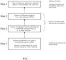
- System1 is governed by a Policy that mandates that it should be connected to System2.
- System1 and System2 both have respective Agents installed on them so they can be managed by the Platform. Typical steps may be:
- the disclosure provides methods, Systems, platforms and/or infrastructure which facilitates machine-to-machine public-key distribution between parties that are willing and able to verify each other's identities. It also provides a mechanism for building functionality into the connectivity achieved following the verification and establishment of a communication channel between the respective parties. It also provides systems and methods for creation, configuration, control and maintenance of virtual networks.
- embodiments may be used to establish an encrypted Tunnel and provide virtual network interfaces at either end of the Tunnel so as to emulate a virtual private network (VPN) tunnel between connected Peers.
- VPN virtual private network
- this VPN may encapsulate data packets at layer 2 (using ethernet frames) or layer 3 (using ipv4/ipv6) without the need for a VPN server in the middle. Therefore, embodiments provide a significantly improved VPN architecture for connectivity establishment compared to the prior art.
- Various technical effects arise from this including, but not limited to, the requirement to provide effective protections against known exploits such as ARP cache poisoning. Solutions for addressing ARP cache poisoning are provided herein in accordance with a second aspect of the disclosure, substantially in the section entitled "FAKE ARP".
- any feature described or claimed herein in relation to one aspect of the disclosure may also be present and incorporated into one or more other aspects of the disclosure.
- a feature described or claimed in relation to a method of the invention may also be applicable to a system of the invention, and features presented in respect of one aspect of the disclosure are intended to be relevant to other aspect(s).
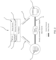
- the disclosure provides a Platform (1) that includes some or all of the following components:
- Platform components may be implemented using dedicated hardware and software provided in one or more datacentres. The disclosure is not limited with regard to any particular implementation architecture or service delivery mechanism.
- Preferred embodiments enable a direct, end-to-end encrypted Tunnel between Systems 6, 7 via the public Internet with a virtual network interface on each system operating at either Layer 2 or 3 in a manner that is transparent to existing applications.
- Alice and Bob are operators of systems System1 and System2 respectively. These systems are managed (Tagged) in compliance with Policies that have been set by the Account Owner/administrator (Carol) and, therefore, do not need to provide further evidence of intent to connect.
- the Policies that are specified by Carol are pushed by the Platform's DS to the respective Agents installed on the Systems and dictate what the Agents (13) are permitted or not permitted to do with respect to connectivity to Agents on other Systems.
- the Agent (13) on System1 (6) asks the DS ( Figure 2 , 4 ) for the necessary information for the required connection.
- the Agent (13) on System2 (7) asks the DS for reachability information for System1 if the Policy associated with System2 specifies that the connection should be made, and the DS facilities the connection.
- the Agents on systems 1 and 2 mutually request an introduction to one another via the DS but they do this without the need for manual intervention or demonstration of cooperation/intent beyond that which is specified by their system's Policy or Policies.
- the Agent on each System asks the DS to grant it a subscription to the other System by the other System's Certificate Common Name as given to it by a Policy push from the DS.
- each Agent will be provided with a set of server reflexive Connection Candidates and a relay service Candidate that can be used to reach the other System on either the local network or Public Internet. Therefore, System1 requests a subscription to system2 at the DS. The DS may acknowledge the request.
- Carol enrols Systems 1 and 2 with the Platform. Following registration, enrolled Agents on the respective systems will be able to use the Platform's services to enable construction of Tunnels with other Agents on other Systems that have also been enrolled.
- Carol registers an account on the Platform and creates one or more unique Enrolment Keys, generated by the Platform 1.
- the Agents on Systems 1 and 2 subsequently receive respective Enrolment Keys from Carol via trustable pre-existing channels.
- an Enrolment Key might be limited or restricted to a specific number of uses. In other embodiments, an Enrolment Key might not have a limit in respect of the number of times it can be used. Moreover, an Enrolment Key might either be set to approve new enrolments automatically, or new enrolments may need to be manually approved by Carol before the enrolling system is accepted into the Platform.
- Enrolment Keys are arbitrary, in that their values or format are not determined in respect of the System that they relate to and are generated by an algorithm that comprises a random or pseudo random key generation process.
- an Enrolment Key may take the form:
- An Enrolment Key allows the Agent (13) on a newly added system to interact with the Platform's Certificate Authority ( Figure 2 , 5 ) but does not create or denote a relationship with the enrolling System. It is a secret, confidential value that is only disclosed to Carol or other Platform Administrators for Systems that are to be enrolled with the account at the Platform.
- an Enrolment Key may be passed from Carol to an end-user (Alice/Bob) so that the end-user can self-enrol although it should be noted that the Enrolment Key is a sensitive value and should be treated as a secret.
- the enrolled System subsequently follows the relevant connection flow for either "managed Agent mode” or "unmanaged Agent mode".
- Managed mode is a connection flow that is governed by Tags and Policies.
- Unmanaged mode is a connection flow wherein Tags and Policies have not been specified for use with the System and therefore an explicit, out of band intention to connect must be established between or provided by System Administrators.
- System enrolment is an additive or subtractive process in the sense that following creation of Carol's account, neither System1 nor System2 are known to the Platform.
- Carol can then use the Platform's portal to start building and defining a network of connectable Systems for her organisation.
- connectivity is subsequently established between her Enrolled Systems, the connection may be achieved using either the unmanaged technique disclosed in WO 2017/060675 (i.e. the "you tell me your certificate name and I will tell you mine” approach) or the centrally managed "Tags and Policies” approach described herein, and which involves the use of Policies and possibly Tags that are defined by Carol for specific Systems and pushed to those Systems at the appropriate time(s).
- An Enrolment Key could be a single-use key for adding a System once and then the key is disabled. Alternatively, the key could be a multi-use key.
- Each Enrolment Key may apply an administrator configured set of initial (possibly default) set of Tags to an Enrolling System. Therefore, an Enrolment Key can be associated with a set of rights and rules (which we will describe below in the "Tags and Policies" section) and any System that is enrolled with that Enrolment Key will automatically inherit the associated rights, rules and constraints. This means that Carol does not need to manually define the rights, rules or constraints for each System upon enrolment, as the Platform can apply them automatically using the Enrolment Key.
- Tag membership via an Enrolment Key can be viewed as a point-in-time snapshot of a Carol's decisions or management Policies.
- Carol can designate an Enrolment Key for use with certain types of Systems.
- the Platform allows Carol to attach a label or description to each of her Enrolment Keys. This makes it easier for Carol to recognise the Enrolment Keys and their designated purpose as "raw" keys are long strings of hexadecimal digits which are not easily handled by humans. For example, if Carol wishes to enrol a new laptop to her Organisation account she might use an Enrolment Key labelled "Laptop key" to enrol that system with the Platform.
- Enrolment Keys may only apply Tags to Systems that are being enrolled if the following conditions are true:
- an Enrolment Key identifies the organisation that an Enrolling System belongs to, and Carol can specify a set of "initial" Tags to be assigned to that key such that the set of Tags are applied to all subsequent systems which are enrolled using it.
- Carol labels as "All Staff Enrolment Key”. This could be configured to automatically apply the tag "all-staff” to Alice's laptop when it is enrolled using that particular Enrolment Key. This is, however, the extent of the relationship.
- Carol is able to add more Tags to the user's laptop e.g. "guest-computers", “uk-laptops” etc. or she could remove some or all the Tags.
- the Enrolment Key is irrelevant and has no direct or lasting relationship with an Enrolled System.
- the Platform allows Carol to remove or disassociate a previously Enrolled System from an account. Over time Carol will most likely wish to reconfigure the state of connectivity defined at the Platform. Systems will be added or removed and Carol will need to maintain and reconfigure the remaining Systems enrolled with the Platform. This can be achieved by removing the link between the System and the account and/or Enrolment Key with which the System is associated at the Platform.
- the Platform provides a tool for the specification, configuration, re-configuration and/or update of a computer-based network.
- the disclosed use of the Enrolment Key reduces the amount of time, effort and processing resources required when specifying or reconfiguring the network.
- the described use of Enrolment Keys provides significant technical advantages, including but not limited to:
- a Tag can be described as a label for a category, class or type of enrolled System which allows Carol to group certain Systems together which share similar characteristics (i.e. business unit, security level or function).
- Tags can be viewed as denoting a System's membership within a group or class, and are binary in the sense that a given System is either a member of that defined Tag, or it is not.
- the relationship is many-to-many in that a particular System can be a member of multiple classes by having multiple Tags applied to it, and Tags can apply to multiple Systems.
- Tags can be used to logically associate or group together Systems which share either a common function, role or purpose.
- the function may be a technical function or may be related to the operational activities of an organisation e.g. business entity, organisation or unit thereof (e.g. accounts team, developers, board members).
- a Tag may apply to Systems which share a common purpose or function (e.g. web servers, database servers) or a common security level (e.g. home workers, system administrators) or some other shared criteria or attribute. This shared attribute gives rise to a relationship that is reflected in the Tag membership.
- Tags can be described as free-form text labels attached to one or more systems that are enrolled with an account on the Platform.
- Tags allow Carol or Platform Administrators to group or logically associate Systems which share similar characteristics (i.e. business unit, security level or function). They can be manually added to an enrolled System by Carol, or an Enrolment Key can be configured to apply an initial set of Tags to enrolling Systems.
- Tags can include zero, one or more Tag Membership Requirements which define when and/or how a resource belongs to a Tag class.
- the Tag Membership Requirements may be encoded in machine executable form and subsequently enforced by Policy. For example, a Tag for "Guest laptop” may have the requirements that the Tag only applies if the tagged system:
- Carol can specify a granular level of constraints and permissions which apply to members of each Tag, and can specify when Systems become or cease to be active members of that Tag.
- Tag Membership Requirements are additive in the sense that they must all be met in order for a System to be counted as an active member of a Tag. For example, if Carol has associated a particular System with the "Guest laptop" Tag, and that System does not have anti-virus protection enabled as per the Tag Membership Requirements, it is not considered to be an active member of the Tag regardless of where it is located.
- a "Workstation” Tag is added to all Systems which function as user workstations within an organisation but Carol wishes to specify that the given Systems are should only inherit the relevant permissions for workstations while they are physically location within the office.
- a work laptop may have certain connectivity to other Enrolled Systems when in the office, but not when travelling.
- Carol adds a "Public IP Address requirement" to the "Workstation” tag that specifies the public IP ranges of the office network(s).
- the Platform attempts to validate the Tag requirement for that System. If the System is not at the office the validation fails and the "Workstation” tag temporarily disables for that particular System.
- the laptop is brought back to the office and connects to the Platform, the Tag Membership Requirement is met and the "Workstation" Tag enables again for that System and, by extension, any Policies which reference that Tag thus restoring connectivity.
- the Tag-based approach may be implemented on a per System basis.
- a System is removed from Tag Membership Requirements that may have a consequential effect on the application of a Policy.
- the Policy itself is not disabled, the System is simply disabled from Tag membership and, by extension, because the only relationship between a System and a Policy is via Tag membership the Policy ceases to apply to that particular System.
- Systems may be "active" or "inactive" in relation to a Tag.
- a System's Tag membership can be active or inactive at a given point in time based on the dynamic state of a set of Tag Membership Requirements that each System may, or may not meet, and thus the applicability of a Tag to a given System is determined dynamically rather than being static.
- Tag membership can change from active to inactive and vice versa. For example, a particular System may have the tag "Office Workstations" applied to it by Carol or a Platform Administrator, but if that System is not in the office the System is simply not active in respect of the Tag, even though the Tag relationship remains.
- Tag Membership Requirements could include:
- Tag Membership Requirements can be dynamic and can apply/not apply at a given point in time.
- the status of "active" or “not active” with regard to Tag membership can be determined on an event-driven basis, such that a detected event can trigger a change of Tag membership status for a given System.
- the triggering event can be detected by an event listener or monitoring component, or can be communicated to the Platform from an internal or external source.
- a GPS tracker may send a signal to indicate that a given System has been taken out of the office or other permitted geographic location, or an internal clock may indicate that a process has been running for a given length of time etc.
- the type or nature of possible Tag requirements is infinite and are configured by the Platform Administrator role or Carol.
- Tag-based approach An advantage of the Tag-based approach is that Carol does not need to define, apply and review the settings, permissions or controls for individual Systems. Instead, she can define a System as belonging to a particular logical group of Systems by applying a Tag to it and that System will then be bound by the Tag Membership Requirements of that Tag. This provides a simple, efficient and secure way of managing and controlling systems on a virtual network. Tags, however, become even more useful when used in conjunction with Policies.
- Policies comprise Tags.
- a Tag is a way of applying Policies to Enrolled Systems without the need for individual settings for each System.
- Policies are also set by Carol or the Platform Administrator via the Platform's Portal interface.
- Tags relate to Systems which share similar characteristics (e.g. because they belong to the same business unit or share a common security level or function)
- a System may be a compliant, or non-compliant member of a tag.
- System membership of specific Tags is binary in nature, a given System either is Tagged, or it is not.
- Policies define rules which are applied to permit, restrict or deny the flow of information between Systems based on their Tag membership and compliance status with the Tag Membership Requirements.
- While Tag membership is defined on a per-System basis, Policies are defined at a global level within each Account and are composed of Tags. Systems which are "active" in respect of a given Tag may inherit one or more Policies which govern traffic flow and connectivity between said systems. Policies can be influenced or dictated by one or more factors. For example, these might include one or more of: System identity, end-user identity, point-in-time security attributes of the end-user's Systems and metadata or factors such as network location, geographic location, time of day and any other heuristics that might feed into a go-no go decision from the Policy engine.
- Laptop1 may be a member of the Tags: “uk-laptops”, “developers” and “all-staff”
- Laptop2 may be a member of the Tags: “uk-laptops”, “administrators”, “all-staff”.
- Carol may set the following Policies:
- Policies define and constrain which Peers an Enrolled System can communicate with and how. If a particular Policy does not include a particular tag, then Systems with membership of the omitted tag will not have any connection to systems of Tags which are and no tunnel for communication will be established between them. Tags unreferenced by Policy and by extension any member Systems remain unaware of one-another and any connectivity implied by Policies which reference other Tags.
- Enrolled Systems act independently of each other in accordance with the Policies that have been assigned to them by Carol and in response to the Policies that are computed and sent to them by the DS. If a Policy specifies that System1 should connect to System2, System1 will ask the DS for an introduction and vice versa with System2. However, System1 and System2 do this independently of one another without any shared knowledge of what the other is doing.
- Policies specify when and how Systems within that Tag membership can connect, send and receive data. Traffic Rules govern Traffic Flows between Enrolled Systems and are specified as receive-oriented rules. In other words, Traffic Flow controls are only defined from the perspective of the receiver side of the Policy. Send-side restrictions are not defined because defining who can receive what and from whom also implies sender restrictions.
- a System may be a member of multiple or no Tags. Additionally, or alternatively, a Tag may be referenced by multiple or no Policies.
- the Platform is "default deny" with respect to visibility and Traffic Flow between Peers until a Policy is defined by Carol or a Platform Administrator that allows it.
- the Policy controls visibility and connectivity between Enrolled Systems. As these Systems are at either end of a communication channel, when viewed from the perspective of one of the systems they can be perceived as the sender or receiver of network traffic at a specific point in time.
- a Tag attached to the Sender side of a policy that relates in some way to a receiver Tag implies that all sender Systems that have that Tag assigned have permission to connect with, and send data to, all of the receiving Systems that have the corresponding receiver Tags assigned. However, until a Tunnel is actually established between System1 and System2 the Traffic Flow is not enabled.
- Traffic Rules may be required to enable a Traffic Flow. Traffic Rules define the network traffic that is permitted between a given sender and receiver, and Traffic Rules can control a variety of connection behaviours. Examples of traffic rules may include, for example, but are not limited to:
- a sender may initiate Traffic Flows to a receiver, by not vice versa.
- Traffic Flow restrictions (which are also known as access control lists or "ACLs") are defined by Policy but only specified on the receiver side of that Policy.
- ACLs access control lists
- both sides of a connection apply the same Policy, and therefore if a Policy only permits System1 to receive a particular type of traffic from System2 (for example, tcp/3389 traffic, then System1 can only send tcp/3389 traffic to System2).
- the application of Traffic Rules happens at both ends of the Tunnel on the sender and the receiver side, even though Traffic Rules are defined only on the receive side of the Policy.
- the send side restrictions are implied by the Traffic Rules defined for the receiver side of the Policy.
- the Policies described above may be implemented via a "Policy Engine”.
- the Policy engine may perform the following roles:
- this connectivity is achieved by a machine-to-machine, automated process facilitated by the Platform without the need for manual intervention.
- This provides the benefit of being easier, more efficient, secure and simpler for end users; it reduces the likelihood of human-originating errors and thus the time, resources etc required to establish the desired connectivity and communication channel.
- the solution also scales more effectively to larger groups of participants avoiding the need for each party to directly exchange Certificate Names with every other.
- embodiments of the disclosure provide:
- the Platform's DS send Connection Candidates to the Agent on both Systems which can be used to attempt to establish network connectivity directly between the two Systems.
- System2 may receive one or more Connection Candidates that the Agent software can use to attempt to reach System1. This can be referred to as "a network address or network reachability information".
- the DS facilitates the introduction between Systems 1 and 2.
- Each Connection Candidate is made up of an IP address, a port number and a protocol which represents the network address, or network reachability information for another System.
- System1 and System2 may have firewalls or have routers which use network address translation (NAT) to protect their networks.
- NAT network address translation
- System1 Normally, if System1 has sent traffic out through its firewall, System2 is able to respond back to the Agent on System1 through System1's firewall due to an assumed permission based on System1'sinitial outbound communication.
- System1 when System1 tries to connect with System2, System2's firewall will reject System1'sunsolicitied communication.
- the DS makes an introduction between Systems 1 and 2 simultaneously, so when System2 also tries to communicate with System1 momentarily later, System2's communication appears to System1 to be a reply to its initial connection request packet and so System1'sfirewall allows System2's communication through.
- System1 can then respond to System2's communication and now both parties have established a network connection to one another from behind firewalls which are closed to unsolicited ingress traffic, sometimes known in the art as stateful firewalls. Both firewalls remained closed to unsolicited ingress traffic, and there was no underlying network reconfiguration required but both System1 and System2 are now able to exchange network traffic with one another.
- This is a technique known in the art as UDP or TCP hole punching (as it is frequently used with the UDP and TCP protocols) and can be performed in respect of UDP or TCP network traffic.
- the connection can alternatively be made via a relay service provided as a component of the Platform.
- VCF Virtual Network Interface
- the VIF component emulates a physical ethernet cable, and has an IP address, subnet and performs the same role and provides the same functionality as a physical network adapter.
- System1 tries to talk to a System2
- the communication is routed via the VIF on System1, through the Tunnel and in to the VIF at System2. Therefore, the direct, secure communication channel 10 that has been established between System1 and System2 by the operations described above emulates a direct network connection with the addition of encryption.
- the two Systems at either end are agnostic to the fact that they are communicating via an emulation carried by the Tunnel, and existing applications (12) can send packets and network traffic back and forth directly across the Tunnel as if they were doing so in the conventional manner using a traditional Internet-based network.
- the pipeline consists of zero or more modules which individually process the received data packet and (may) decide to take specific actions on the received packet such as DROP, ALLOW, ALTER or INJECT. If one module decides to DROP a packet, the remaining modules in the pipeline will never get to see the received traffic and it will not be delivered to the local TAP virtual network interface for applications (12, e.g. the web browser) running on System1 to consume. To that end, each module in the processing pipeline is assigned a priority number which determines the order in which each module has an opportunity to process the received data packet. Each module has the opportunity to process data received either "From Peer" or "From TAP", and each module may also store metadata or other information persisting from one invocation to the next.
- the disclosure provides an improved approach for capturing and exchanging the intent that two or more Systems need in order to connect with each other.
- the DS provides the necessary information to the Systems because the DS has a stored record in the form of a Policy configuration that records Carol's intent to connect the systems. Therefore, the DS is pre-authorised to make the introductions between the Systems and provides them with the necessary Connection Candidates.
- the Tags and Policies enable a many-to-many relationship, as a given System can be a member of more than one Tag, and thus will inherit the Policies (rules) of each Tag that it is associated with a given Policy.
- Carol is able to describe and define connectivity in her Account by applying Tags to the relevant systems and creating Policies composed of those Tags. This enables the construction of complex topologies but easy-to-configure connectivity topologies.
- embodiments enable a transition from local i.e. device-level control of Tunnels to a centrally controlled approach i.e. at the Platform, defined by Carol or Platform Administrators.
- Carol can push changes and reconfigurations down to multiple Systems across the Account in one simple, efficient and quick operation that is performed via the Web Portal. Also, there is no need to perform an in-person, out-of-band exchange of Certificate Names as disclosed in WO 2017/060675 because the information that is exchanged is provided by a Discovery Service in the form of a computer-implemented Policy shared by and associated with the Enrolled Systems. Thus, the exchange is performed machine-to-machine rather than manually and mutual intent is established using a pre-determined/pre-defined/stored set of Tags and Policies which provide a priori knowledge of which systems have a mutual intent to connect. This not only saves time, resources and processing effort but it provides a more secure exchange mechanism because it reduces the likelihood of interception by any unauthorised parties. It also means that out-of-band challenges such as time zone or language differences are avoided.
- VPNs are an example of an overlay network.
- Overlay networks are built on top of the physical infrastructure of an underlay network, such as the Internet, which serves as the data transportation and packet routing mechanism.
- This physical infrastructure comprises devices such as servers, switches, firewalls and routers. See, for example, https://en.wikipedia.org/wiki/Overlay_network. Therefore, while the VPN provides a logical, abstracted layer of inter-system communications, the data packets are, in reality, encapsulated and carried by the underlay network, but usually in conjunction with encryption where the secret keys are not known to intermediary devices on the underlay network which therefore cannot decrypt the encapsulated packets they carry (hence the private in virtual private network).
- Devices on the underlay network route traffic between source and destination Systems via standard routing protocols and Internet connectivity (or other interchangeable medium), and packets are delivered based on the destination's IP address and subject to any configuration of the underlay network devices.
- each IP address is mapped to an Ethernet address, known in the art as a MAC address, and the behaviour and resolution of MAC addresses into IP addresses is known as and described in RFC 826, An Ethernet Address Resolution Protocol (ARP).
- ARP An Ethernet Address Resolution Protocol
- the role of ARP is to translate the IP address used by the underlay network into an Ethernet address that is compatible with operating systems running on devices within the LAN.
- IP packets are encapsulated and carried by Ethernet frames.
- OS operating system
- the OS (11) attempts to resolve this by querying a look-up table that it maintains, known as the ARP cache, which lists known IP addresses that it has previously encountered and their corresponding MAC addresses.
- the OS finds an existing entry for the IP address in question, it retrieves the corresponding MAC address from the ARP cache and uses it in the construction of the data packet which is then placed onto the network to be routed to the specified destination. If no existing entry can be found, however, the OS broadcasts an ARP request to all systems in the LAN to ask if any of them are identified by that particular IP address. If a receiving system or device on the LAN recognises the IP address as its own, it responds to the query by providing its own MAC address. The OS (11) adds the responders MAC address to its ARP cache table for future reference, and the data packet is constructed and placed onto the network. Any future traffic that is to be sent to the same IP address will not require another ARP request, because the MAC address will be available to the OS from its ARP cache.
- the Platform enables creation of a Tunnel which exists as a peer-to-peer overlay network, that may carry encapsulating Ethernet frames between connected Peers across the underlay network e.g. Internet. Therefore, when traffic is sent from System1 to System2, it has to be transported via the physical infrastructure of the underlay layer. However, the IP addresses and subnets of the overlay (VPN) are different from the IP addresses used at the underlay level.
- VPN IP addresses and subnets of the overlay
- Systems enrolled with the Platform receive, from the DS, one or more potential Connection Candidates that they can use to reach other Enrolled Systems.
- System1 receives one or more potential Connection Candidates that its Agent can use to attempt to reach System2.
- the Connection Candidates comprise at least an IP addresses and port number that may be used to connect the systems. After connection, data flowing between the connected systems is sent directly from peer-to-peer using their respective IP addresses, and each Agent within the VPN knows the VPN IP addresses of other Peers which it is able to connect with.
- System1 now wishes to send a data packet to System2.
- This spurious address is a MAC address which appears to be genuine but is, in fact, false and is not the real MAC address for System2.
- the technique of using spurious MAC addresses may, therefore, be referred to herein as a "Fake ARP" technique.
- the spurious MAC address can be generated in any suitable way such as, for example, using a random or pseudo-random generation technique, or could be generated using a deterministic approach. Both the source and destination MAC addresses in the data packet may be spurious.
- each Agent maintains its own record of spurious MAC addresses that it has generated for systems that are enrolled with the Platform and that it is able to connect with. Therefore, Agent1 may comprise, or have access to, a database or other repository of fake MAC addresses that it has associated with the IP addresses of Peers. Each time System1 wishes to send data to a given Peer, the Agent will use the same fake MAC address that it has generated and associated with that peer. The sending and receiving Agents do not need to agree on the MAC addresses that have been put into a data packet because they are irrelevant to them.
- the Agent on system1 receives an inner data packet with a MAC address from System2 that does not match the entry in its fake ARP cache for System2, it can simply substitute it for its pre-stored fake MAC address before handing the packet to the OS because deliverability has already achieved (the two Peers have all the reachability information they need to send traffic between them). Consistency for the OS is achieved by ensuring that it always receives the same source MAC address for a given sender. As long as the MAC address meets the expected format, the OS has no way of discerning that it is a spurious address and accepts it as genuine. Therefore, it is irrelevant what the sender specifies as the source MAC address in the inner packet because the receiving system will exchange it for the fake address that it has chosen and associated with that sender.
- Agent1 After the fake MAC address has been provided in the "Source MAC address" field of the inner packet, Agent1 encrypts the inner packet and inserts it into the data section of a further data packet which we will refer to as the "outer data packet".
- System1 In order to send this packet across the underlay network, though, System1 needs to know the source and destination MAC addresses for the two systems as these are required for completion of the data packet fields that the underlay will need to use. The OS at the receiving end will need to know the MAC addresses for the source and destination. While System1 knows its own MAC address it does not know System2's, so it sends an ARP request to a broadcast address as known in the prior art. In response, System1 receives a MAC address for System2. It uses the received MAC address to complete the field for the destination MAC address in the outer packet.
- the outer data packet now contains all the necessary data to satisfy the underlay network's requirements, and it also includes the encrypted inner data packet as data.
- Agent1 then sends the outer data packet for transportation across the network to the destination specified in its IP address field, which is System2's IP address.
- the Agent on System2 unpacks the outer data packet to access the inner data packet and decrypts it. It ignores the MAC address as it does not need it for deliverability purposes and sends the desired data to the specified IP address.
- embodiments of the disclosure provide security advantages in that the threat of ARP cache poisoning is made irrelevant.
- an attacker would never substitute a real MAC address for a spurious one because this would defeat their goal of diverting traffic to their system. Therefore, the attacker substitutes their own MAC address for the intended one, their own address being a genuine MAC address associated with a network device, albeit unauthorised.
- the "Fake ARP" technique disclosed herein can be implemented as module or component of an Agent installed on an enrolled system as described above, which we will refer to as the "Fake ARP" component.
- This component may be operative to generate the spurious MAC addresses for other enrolled systems that it is able to connect with via the Platform, maintain a "Fake ARP cache” to record the spurious MAC addresses that it generates, look up the spurious MAC addresses in the fake ARP cache when a data packet is to be sent out, at least facilitate provision of the fake MAC address in the inner data packet.
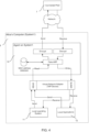
- the Fake ARP component acts on the two arrows which point inwardly to the Fake ARP component which is arranged to interface with the virtual network interface (TAP device) installed on the enrolled system, and also with the underlay network.
- TAP device virtual network interface
- the Agent checks the sender protocol (either UDP or TCP), origin IP address and source port of the packet and matches it to existing knowledge of an established connection.
- This first step provides an understanding of which peer sent the message and is performed because once the initial handshake between the systems is completed, subsequent messages will be encrypted and so the receiving system must use the correct decryption key to access the received data. Evaluation of the data packet starts after the receiver has successfully decrypted the encrypted packet send by the connected peer.
- FIG. 5 illustrates data flow from a connected Peer.
- the first step is to determine if the packet is an ARP frame or not.
- the Fake ARP module only interacts with the traffic flow if the module itself is enabled. If enabled, ARP traffic is prohibited from crossing the Tunnel, so the packet is discarded and the local ARP cache table for connected Peers is constructed without requiring communication with said Peers.
- the Fake ARP module In contrast, if the Fake ARP module is disabled then the module simply enters a mode which appears as a "pass through”, recording the sender's MAC address and passing the packet unaltered to the TAP. If the received packet is neither ARP nor IPv4 traffic, the module again enters "pass-through” mode and writes the packet directly to the TAP.
- the received packet may need to be modified in order for the Fake ARP module to function.
- the received traffic is an IPv4 packet.
- every Ethernet frame requires a MAC address.
- the sender is responsible for setting the MAC address of the Ethernet frame, but this gives rise to the potential for ARP cache poisoning attacks. Therefore, the fake ARP module performs two tasks: 1) it prevents ARP traffic from crossing the Tunnel between the two connected peers, but in doing so it also prevents them establishing a common understanding of each other's MAC addresses; 2) instead then, the Fake ARP module randomly generates a MAC address for each connected Peer and replaces the MAC address on any received packet with the locally generated MAC address for said Peer. By doing this, the sender is unable to influence the receiver's operating system ARP table.
- each peer has a unique virtual IP address
- Peers communicate with each other primarily by sending packets to one another setting by the destination IP address to that of their connected Peer's virtual IP address.
- System1 is 100.64.0.10
- System2 is 100.64.0.20.
- These IP addresses only have meaning when System1 and System2 are connected using the disclosed Platform. Without that connection, these IP addresses lose their meaning to each party. If the received packet is destined for the receiver's virtual IP address then in order to complete the MAC address manipulation of the packet we set the destination MAC address to be the receiver's (spurious) local generated MAC address. The sender could not have done this as it has no knowledge of the receiver's MAC address (because the Fake ARP module prevents ARP traffic from crossing the Tunnel).
- the Fake ARP module only handles ARP packets, the first action is to evaluate each packet and only interact with ARP traffic entering the module. Furthermore, it only processes ARP frames which are of the ArpRequest type, where the operating system is attempting to acquire data to update its ARP table with MAC addresses for foreign hosts (connected Peers) on the network. Any other ARP traffic message types are dropped.
- Non-ARP traffic received from the local Virtual Network Interface is anticipated to either be unicast or broadcast traffic and the module allows these packets to continue in the processing pipeline to be sent on to any connected peers assuming no other successive modules in the pipeline make a contrary decision.
- the fake ARP module will not allow this packet to cross the Tunnel to reach any connected Peers. Instead, it will create a fake ArpReply packet locally and send it back to the operating system.
- the Agent records both the SenderHardwareAddress (i.e. a MAC address: 00:00:00:00:00:00) and SenderProtocolAddress (i.e. IP address: 0.0.0.0) from the ArpRequest packet and stores them in an in-memory database.
- the operating system may attempt to direct traffic via default route. Therefore, the Fake ARP module generates a random MAC address and sets the first two bits of the first byte to indicate that this address is both locally administered, and configured for unicast traffic. This MAC address is then stored by the Agent and assigned to whichever IP address it selects as a fake default route.
- the Fake ARP module edits the Request packet, sets the SenderHardwareAddress to the pre-generated randomly selected MAC address for the fake default route and sets the SenderProtocolAddress to be the last usable IP address of the subnet.
- the module is effectively editing the Request Packet (rather than allocating a new data structure) to set the sender fields to appear to have originated from the original destination the packet targeted, but the destination does not actually exist. This is the reason for the Fake ARP module intervening to intercept the ARP request, modify the packet to look like a legitimate reply and send it back as an ARP response. In effect, the Fake ARP module fakes a reply from the relevant connected Peer.
- the ARP Request packet received may not be targeting a unicast destination IP address.
- the Agent does not need to fake a response and the original packet may be discarded by the module without eliciting a fake ARP response back to the OS.
- the Fake ARP module re-writes the sender fields of the ARP Request packet so it can be sent back to the operating system purporting to be an authentic ARP reply to the original ARP request.
- the OS has attempted to ascertain the MAC address corresponding to a virtual IP address of a connected Peer.
- each Agent generates a random MAC address to associate with its far-side Peer.
- the OS attempts to discover the MAC address for that Peer's virtual IP address by placing an ARP request onto the network.
- This flow alters the ARP Request packet to move the original sender information to the destination fields of the packet and populates the now empty sender information with the locally held information about the remote Peer (i.e. the spurious MAC address and virtual IP address).
- the operation field is also switched from Request to Response.
- the VPN acts as a router and all traffic passes through it. Therefore, the VPN server may police the traffic for fake or illegitimate ARP replies. Moreover, it is able to see it. If it encounters a MAC address that it suspects may be suspicious or malicious in nature, it may attempt to resolve the MAC address. Therefore, in the traditional architecture, ARP poisoning is typically addressed either on the VPN server or on network devices connecting systems together like network switches. By contrast, systems which are peers in embodiments of the disclosure generate false MAC addresses for themselves and every other peer they are connected to. As the VPN server is the overlay network's router in the traditional model, ARP cache poisoning may be a problem for prior art VPNs unless the VPN server comprises a solution to address it.
- the enrolled Peer still comprises a switch that all traffic moves through but instead of it being a VPN server on the underlay network all traffic on the overlay is encrypted so none of the components of the underlay network can see it. Therefore, the underlay switch cannot see nor police the traffic.
- the underlay network takes care of the transportation, routing, and delivery of the data, by the time the data is received at the receiving system and is decrypted by its Agent, the part of the data transfer process which would typically require MAC addresses has already been performed. Therefore, the Agent is able to use spurious MAC addresses in the packets simply for compliance with required protocol formats. The Agent ensures that the MAC address for the source is consistent with historical events when it hands the packet back to the OS.
- embodiments of the disclosure emulate a bridged LAN when running in OSI model "Layer 2" mode. No routing takes place on the virtual overlay network and, therefore, there is a need for protection against ARP cache poisoning.
- Embodiments may operate at either Layer 2 level (transporting Ethernet frames and associated payloads) or at Layer 3 (transporting IP packets and associated payloads).
- Layer 3 transporting IP packets and associated payloads.
- ARP cache poisoning protections are not required as ARP traffic is carried by Ethernet frames, not IP packets. Therefore, ARP cache protection is not relevant in Layer 3 mode because ARP traffic itself cannot be exchanged between connected peers.
- some embodiments may comprise systems running on different operating systems. Some may operate at Layer 2 (e.g. Windows and Linux) while others (e.g.
- Mac OS do not allow the creation of a Layer 2 virtual network interface, thus requiring connectivity at Layer 3.
- System1 could be sending Ethernet frames while System2 could be sending IP packets.
- embodiments may comprise a "middle layer" that removes the Ethernet frame from anything System2 receives from System1, and in reverse adds an Ethernet frame header to the IP packets System1 receives from System2.
- the first and second systems may each be:
- the method may comprise: introducing, for connection, the first system entity (6) to the second system (7) if an explicit or implied permission (and/or intention) to connect has been provided to and/or stored at the Platform (1) for, in respect of and/ or by (possibly both) the first and second systems (6, 7).
- the permission/intention may be provided by an authorised or controlling party e.g. administrator or Account Owner.
- the permission/intention may comprise at least one tag as described herein.
- the first and/or second systems may be computer-based resources, comprising one or more electronic or virtual devices.
- the introduction may be performed by a discovery service provided by or associated with the computer-based Platform.
- Embodiments of the disclosure may provide methods and apparatus for facilitating, or enabling the provision or emulation of a virtual network adapter at respective ends of a communication channel. It may also be referred to as a solution for providing a computer-based overlay network on top of an underlay network. It may be implemented as a software-based agent that is downloaded and installed on each system that is to be connectable and/or managed via the platform.
- the platform can be cloud-based, distributed and/or SaaS-based.
- the method may comprise downloading and/or installing an Agent (client) substantially as described herein on the first or second system(s).
- embodiments of the disclosure may be described as comprising a computer-implemented method for establishing or facilitating connectivity between a plurality of systems over an overlay network.
- a computer-implemented method for establishing or facilitating connectivity between a plurality of systems over an overlay network Preferably:
- This component may be referred to as a "Fake ARP" component.
- This component may be operative to generate spurious MAC addresses for other enrolled systems that it is able or permitted to connect with via the Platform, maintain a "Fake ARP cache” to record the spurious MAC addresses that it generates, look up the spurious MAC addresses in the fake ARP cache when a data packet is to be sent out, and/or at least facilitate provision of the fake MAC address in an inner data packet.
- a computer-implemented method comprising:
- Clause 2.2 A method according to clause 2.1, wherein: the data packet comprises a further data packet which has been encrypted.
- Clause 2.3 A method according to clause 2.1 or 2.2, wherein: the data packet is sent or received via the overlay network based on an IP address associated with the second system.
- the spurious MAC address is a spurious MAC address for the first system and/or the second system.
- Clause 2.10 A method according to clause 2.9, and comprising the step: enrolling the first and second systems at the Platform in association with an Enrolment Key.
- a computer-implemented system comprising:
- a computer-implemented system comprising:
Landscapes
- Engineering & Computer Science (AREA)
- Computer Security & Cryptography (AREA)
- Theoretical Computer Science (AREA)
- General Engineering & Computer Science (AREA)
- Computer Hardware Design (AREA)
- Signal Processing (AREA)
- Computer Networks & Wireless Communication (AREA)
- Software Systems (AREA)
- Physics & Mathematics (AREA)
- General Physics & Mathematics (AREA)
- Health & Medical Sciences (AREA)
- Computing Systems (AREA)
- General Health & Medical Sciences (AREA)
- Bioethics (AREA)
- Data Exchanges In Wide-Area Networks (AREA)
Claims (15)
- Computerimplementiertes Verfahren zum Herstellen, Umsetzen und Ermöglichen von Konnektivität zwischen einem ersten System (6) und einem zweiten System (7), wobei jedes System:bei einer computerbasierten Plattform (1) registriert ist; undauf der Plattform einem kryptographischen Schlüssel und einem Zertifikatnamen zugeordnet ist;das Verfahren umfassend:Definieren und/oder Speichern einer Richtlinie, die Verkehrsflusskriterien definiert, und/oder eines Tags, das eine Klasse, einen Typ oder eine Kategorie eines Computersystems bezeichnet;Anwenden der Richtlinie und/oder des Tags auf das erste und/oder zweite System; undBereitstellen von Erreichbarkeitsinformationen an das erste oder zweite System, um zu erlauben, dass es sich mit dem anderen System verbindet, wenn, und nur wenn, jegliche und alle Regeln, Kriterien und Anforderungen, die der Richtlinie und/oder dem Tag zugeordnet sind, eine Verbindung von oder zwischen dem ersten System und zweiten System (6,7) zulassen.
- Computerimplementiertes Verfahren nach Anspruch 1 und den folgenden Schritt umfassend:
Anmelden des ersten Systems und des zweiten Systems auf der Plattform in Zusammenhang mit einem entsprechenden Anmeldeschlüssel und optional Konfigurieren des Anmeldeschlüssels, um einen anfänglichen Satz von Tags auf das erste und/oder zweite System anzuwenden. - Computerimplementiertes Verfahren nach Anspruch 1 bis 2, wobei:
die Richtlinie und/oder das Tag mindestens einer Regel, einem Kriterium und/oder einer Anforderung zugeordnet ist, die/das definiert, wie und/oder wann die Richtlinie und/oder das Tag auf das erste System und/oder zweite System angewendet wird. - Computerimplementiertes Verfahren nach Anspruch 1 bis 3, wobei die Plattform:i) mindestens teilweise Cloud-basiert ist; und/oderii) eine Software-als-Service (SaaS) -Funktion bereitstellt; und/oderiii) mindestens eine computerbasierte Komponente umfasst, die dazu betriebsfähig und/oder angeordnet ist, die vorhergehenden Ansprüche durchzuführen;iv) eines oder mehrere aus Folgendem umfasst:ein Portal, vorzugsweise ein Web-Portal (3); und/odereine Zertifikats-Autorität (5); wobei vorzugsweise die Zertifikats-Autorität eine Komponente der Plattform ist und nicht in Zusammenhang mit einem Betriebssystem des ersten oder zweiten Systems oder von einem Lieferanten des Betriebssystems bereitgestellt ist; und/odermindestens einen Relais-Service (2); und/odereine Schnittstelle; und/odereine auf einem Endbenutzersystem installierte Software; und/odereinen Discovery-Service.
- Computerimplementiertes Verfahren nach einem der vorhergehenden Ansprüche, wobei die Richtlinie:i) von einem oder mehreren aus Folgendem beeinflusst oder vorgeschrieben ist: System identität, Endbenutzeridentität, Point-in-Time-Sicherheitsattribute des ersten Systems oder zweiten Systems, Metadaten, Netzwerkstandort, geographischer Standort, Tageszeit; und/oderii) nicht durch die Endbenutzeridentität beeinflusst oder vorgeschrieben ist.
- Computerimplementiertes Verfahren nach Anspruch 5, wobei das Tag:i) mindestens einer Anforderung oder einem Kriterium zugeordnet ist, die/das definiert und/oder steuert, wann und wie das Tag auf das erste System und/oder zweite System angewendet wird; und/oderii) definiert ist durch einen Administrator oder eine Steuerung des ersten und/oder zweiten Systems oder einen/eine dem ersten und/oder zweiten System zugeordnete(n) Administrator oder Steuerung; und/oderiii) mindestens einer Richtlinie oder Regel zugeordnet ist, die definiert, wie oder wann Daten von dem ersten System und/oder System empfangen oder von diesen versendet werden können; und/oderiv) als ein Etikett oder eine Kennzeichnung für eine Klasse, einen Typ oder eine Kategorie eines Rechensystems funktioniert.
- Computerimplementiertes Verfahren nach Anspruch 5 oder 6 und ferner den folgenden Schritt umfassend:i) Bestimmen, ob mindestens eine Anforderung oder ein Kriterium, die/das dem Tag zugeordnet ist, in Bezug auf das erste und/oder zweite System erfüllt ist; und/oderii) Verwenden eines Signals, Ereignisses, Wertes oder einer anderen Metrik, um zu bestimmen, ob mindestens eine Anforderung oder ein Kriterium, die/das dem Tag zugeordnet ist, in Bezug auf das erste und/oder zweite System erfüllt ist.
- Computerimplementiertes Verfahren nach einem der vorhergehenden Ansprüche und den folgenden Schritt umfassend:Ermöglichen oder Herstellen eines Kommunikationstunnels zwischen dem ersten System und dem zweiten System;wobei vorzugsweise die Ermöglichung oder Herstellung:i) nach der Anmeldung des ersten und/oder des zweiten Systems auf der Plattform und deren jeweiliger Verbindung mit einem Discovery-Service (4) durchgeführt wird;ii) das Austauschen jeweiliger digitaler Zertifikate zwischen dem ersten und dem zweiten System umfasst, wobei jedes Zertifikat den kryptographischen Schlüssel und eine dem jeweiligen System zugeordnete willkürliche Kennung umfasst.
- Computerimplementiertes Verfahren nach einem der vorhergehenden Ansprüche, wobei:
eine Zertifikats-Autorität (CA, 5) der Plattform (1) die folgenden Schritte durchführt:
Empfangen, von dem ersten System, des kryptographischen Schlüssels und eines dem ersten System zugeordneten Anmeldeschlüssels; und/oder
Erzeugen, Übertragen und/oder Austauschen eines unterzeichneten digitalen Zertifikats, das den kryptographischen Schlüssel und den dem ersten und/oder zweiten System zugeordneten Zertifikatnamen umfasst; und wobei vorzugsweise der Zertifikatname:i) relativ zu dem kryptographischen Schlüssel kurz ist; und/oderii) willkürlich ist, sodass:
die Identität des ersten Systems oder eines Bedieners oder Eigentümers des ersten Systems nicht oder wahrscheinlich nicht aus der Kennung allein festgestellt werden kann; und/oderiii) seine Erzeugung zufällig oder pseudozufällig ist;iv) eine Auswahl des Zertifikatnamens nicht in Bezug zu der Identität des Systems oder des kryptographischen Schlüssels steht. - Computerimplementiertes Verfahren nach Anspruch 9, wobei:i) der kryptographische Schlüssel und der Anmeldeschlüssel von dem ersten System als Teil eines oder in Zusammenhang mit einer Anfrage auf Ausstellung eines Zertifikats (Certificate Signing Request (CSR)) empfangen wird; und/oderii) der Anmeldeschlüssel von der Plattform erzeugt wird und/oder dem ersten System zugeordnet ist.
- Computerimplementiertes Verfahren nach einem der vorhergehenden Ansprüche, wobei die Richtlinie:i) eines oder mehrere Tags umfasst;ii) Regeln definiert, die auf das erste und/oder zweite System angewendet werden, um den Fluss von Informationen zwischen dem ersten und dem zweiten System auf Basis von Tags, die auf das erste und das zweite System angewendet werden, zuzulassen, zu beschränken oder zu verwehren;iii) definiert und eingrenzt, mit welchen Systemen das erste und das zweite System kommunizieren können.
- Computersystem, umfassend Computerausrüstung, die Ausrüstung umfassend:einen Speicher, der eine oder mehrere Speichereinheiten umfasst; undeine Verarbeitungseinrichtung, die eine oder mehrere Verarbeitungseinheiten umfasst, wobei der Speicher Code speichert, der dazu angeordnet ist, auf der Verarbeitungseinrichtung zu laufen, wobei der Code so konfiguriert ist, dass er bei Ausführung auf der Verarbeitungseinrichtung das Verfahren eines vorhergehenden Anspruchs/vorhergehender Ansprüche durchführt.
- System nach Anspruch 12, wobei das System Folgendes umfasst:
eine Zertifikats-Autorität (5), die dazu angeordnet ist, ein digitales Zertifikat zu erzeugen, umfassend: einen öffentlichen kryptographischen Schlüssel und einen dem System zugeordneten Zertifikatnamen, wobei vorzugsweise die Zertifikats-Autorität eine Komponente einer Plattform ist, die nach einem der Ansprüche 1 bis 11 angeordnet ist, und nicht in Zusammenhang mit einem Betriebssystem des Systems oder von einem Lieferanten des Betriebssystems bereitgestellt ist. - System nach Anspruch 12 oder 13, wobei das System auch eines oder mehrere aus Folgendem umfasst:ein Portal, vorzugsweise ein Web-Portal (3);einen Relais-Service;einen Discovery-Service;und wobei vorzugsweise das System dazu angeordnet oder betriebsfähig ist, eines oder mehrere des Folgenden durchzuführen:einen Anmeldeschlüssel für das erste und/oder zweite System zu erzeugen und bereitzustellen;eine Übertragung des digitalen Zertifikats an das zweite System zu ermöglichen;eine Software-als-Service-Möglichkeit für einen öffentlichen Schlüsselaustausch, Validierung des ersten und des zweiten Systems bereitzustellen;eine direkte Verbindung des ersten und des zweiten Systems unter Verwendung ihrer Zertifikatnamen zu ermöglichen.
- Computerprogramm, das auf einem computerlesbaren Speicher enthalten und so konfiguriert ist, dass es, wenn es auf einem oder mehreren Prozessoren läuft, das Verfahren nach einem der Ansprüche 1 bis 11 durchführt.
Applications Claiming Priority (2)
| Application Number | Priority Date | Filing Date | Title |
|---|---|---|---|
| GBGB2105297.2A GB202105297D0 (en) | 2021-04-14 | 2021-04-14 | Computer-implemented method and system |
| PCT/IB2022/053460 WO2022219551A1 (en) | 2021-04-14 | 2022-04-13 | Computer-implemented methods and systems for establishing and/or controlling network connectivity |
Publications (2)
| Publication Number | Publication Date |
|---|---|
| EP4323898A1 EP4323898A1 (de) | 2024-02-21 |
| EP4323898B1 true EP4323898B1 (de) | 2025-02-26 |
Family
ID=75949646
Family Applications (1)
| Application Number | Title | Priority Date | Filing Date |
|---|---|---|---|
| EP22717445.5A Active EP4323898B1 (de) | 2021-04-14 | 2022-04-13 | Computerimplementierte verfahren und systeme zur herstellung und/oder steuerung von netzwerkkonnektivität |
Country Status (4)
| Country | Link |
|---|---|
| US (1) | US20240195795A1 (de) |
| EP (1) | EP4323898B1 (de) |
| GB (1) | GB202105297D0 (de) |
| WO (1) | WO2022219551A1 (de) |
Families Citing this family (6)
| Publication number | Priority date | Publication date | Assignee | Title |
|---|---|---|---|---|
| US12261966B1 (en) * | 2021-09-01 | 2025-03-25 | Amazon Technologies, Inc. | Systems and methods for server-based trust store discovery |
| US12267793B2 (en) * | 2022-05-19 | 2025-04-01 | Oracle International Corporation | Methods, systems, and computer readable media for synchronization of policy data between network functions in telecommunications networks |
| TW202439798A (zh) * | 2023-03-20 | 2024-10-01 | 華東科技股份有限公司 | 高安全性網路訊息傳遞之方法 |
| US12476844B2 (en) * | 2023-06-16 | 2025-11-18 | Trimble Inc. | Hybrid mesh networking system |
| US20250055919A1 (en) * | 2023-08-07 | 2025-02-13 | Kabushiki Kaisha Toshiba | Communication system, controller, server device and method |
| US20250260682A1 (en) * | 2024-02-14 | 2025-08-14 | Cisco Technology, Inc. | Pinning device identifiers to cryptographic key pairs |
Family Cites Families (4)
| Publication number | Priority date | Publication date | Assignee | Title |
|---|---|---|---|---|
| GB2543072B (en) | 2015-10-07 | 2021-02-10 | Enclave Networks Ltd | Public key infrastructure & method of distribution |
| US10057243B1 (en) * | 2017-11-30 | 2018-08-21 | Mocana Corporation | System and method for securing data transport between a non-IP endpoint device that is connected to a gateway device and a connected service |
| US11467815B2 (en) * | 2019-01-17 | 2022-10-11 | Vmware, Inc. | Package distribution and installation in response to user logon |
| US11582066B2 (en) * | 2019-12-19 | 2023-02-14 | Cisco Technology, Inc. | Techniques for extending a cellular quality of service bearer through an enterprise fabric |
-
2021
- 2021-04-14 GB GBGB2105297.2A patent/GB202105297D0/en not_active Ceased
-
2022
- 2022-04-13 WO PCT/IB2022/053460 patent/WO2022219551A1/en not_active Ceased
- 2022-04-13 EP EP22717445.5A patent/EP4323898B1/de active Active
- 2022-04-13 US US18/555,355 patent/US20240195795A1/en active Pending
Also Published As
| Publication number | Publication date |
|---|---|
| WO2022219551A1 (en) | 2022-10-20 |
| US20240195795A1 (en) | 2024-06-13 |
| GB202105297D0 (en) | 2021-05-26 |
| EP4323898A1 (de) | 2024-02-21 |
Similar Documents
| Publication | Publication Date | Title |
|---|---|---|
| EP4323898B1 (de) | Computerimplementierte verfahren und systeme zur herstellung und/oder steuerung von netzwerkkonnektivität | |
| US6804777B2 (en) | System and method for application-level virtual private network | |
| US11088996B1 (en) | Secure network protocol and transit system to protect communications deliverability and attribution | |
| US9461975B2 (en) | Method and system for traffic engineering in secured networks | |
| US11652637B2 (en) | Enforcing a segmentation policy using cryptographic proof of identity | |
| US8607301B2 (en) | Deploying group VPNS and security groups over an end-to-end enterprise network | |
| US8490153B2 (en) | Automatically generating rules for connection security | |
| US8082574B2 (en) | Enforcing security groups in network of data processors | |
| US11799844B2 (en) | Secure communication network | |
| JP2023514736A (ja) | 安全な通信のための方法及びシステム | |
| WO2012051006A1 (en) | Methods and systems for providing and controlling cryptographically secure communications across unsecured networks between a secure virtual terminal and a remote system | |
| US10218704B2 (en) | Resource access control using named capabilities | |
| KR102584579B1 (ko) | SaaS 기반 데이터베이스 접근제어 게이트웨이 서비스 시스템 및 방법 | |
| US10158610B2 (en) | Secure application communication system | |
| US20080104692A1 (en) | Virtual security interface | |
| US20150381387A1 (en) | System and Method for Facilitating Communication between Multiple Networks | |
| US20250240175A1 (en) | Methods and systems for implementing secure communication channels between systems over a network | |
| Kwon et al. | Mondrian: Comprehensive Inter-domain Network Zoning Architecture. | |
| US12375463B2 (en) | Internet protocol security and security parameter index summarization and data routing | |
| US20250097198A1 (en) | Zero-trust packet routing | |
| US20260067272A1 (en) | Secrets node for supplying credentials to other nodes over a private network | |
| Simpson et al. | Ports and Protocols Extended Control for Security. | |
| Zúquete | Protection of LAN-wide, P2P interactions: a holistic approach | |
| Ngekeh | CONFIGURING AND USING OPEN VPN ON WINDOWS OS |
Legal Events
| Date | Code | Title | Description |
|---|---|---|---|
| STAA | Information on the status of an ep patent application or granted ep patent |
Free format text: STATUS: UNKNOWN |
|
| STAA | Information on the status of an ep patent application or granted ep patent |
Free format text: STATUS: THE INTERNATIONAL PUBLICATION HAS BEEN MADE |
|
| PUAI | Public reference made under article 153(3) epc to a published international application that has entered the european phase |
Free format text: ORIGINAL CODE: 0009012 |
|
| STAA | Information on the status of an ep patent application or granted ep patent |
Free format text: STATUS: REQUEST FOR EXAMINATION WAS MADE |
|
| 17P | Request for examination filed |
Effective date: 20231030 |
|
| AK | Designated contracting states |
Kind code of ref document: A1 Designated state(s): AL AT BE BG CH CY CZ DE DK EE ES FI FR GB GR HR HU IE IS IT LI LT LU LV MC MK MT NL NO PL PT RO RS SE SI SK SM TR |
|
| P01 | Opt-out of the competence of the unified patent court (upc) registered |
Effective date: 20240222 |
|
| DAV | Request for validation of the european patent (deleted) | ||
| DAX | Request for extension of the european patent (deleted) | ||
| GRAP | Despatch of communication of intention to grant a patent |
Free format text: ORIGINAL CODE: EPIDOSNIGR1 |
|
| STAA | Information on the status of an ep patent application or granted ep patent |
Free format text: STATUS: GRANT OF PATENT IS INTENDED |
|
| INTG | Intention to grant announced |
Effective date: 20241004 |
|
| GRAS | Grant fee paid |
Free format text: ORIGINAL CODE: EPIDOSNIGR3 |
|
| GRAA | (expected) grant |
Free format text: ORIGINAL CODE: 0009210 |
|
| STAA | Information on the status of an ep patent application or granted ep patent |
Free format text: STATUS: THE PATENT HAS BEEN GRANTED |
|
| RAP3 | Party data changed (applicant data changed or rights of an application transferred) |
Owner name: ENCLAVE NETWORKS LIMITED |
|
| AK | Designated contracting states |
Kind code of ref document: B1 Designated state(s): AL AT BE BG CH CY CZ DE DK EE ES FI FR GB GR HR HU IE IS IT LI LT LU LV MC MK MT NL NO PL PT RO RS SE SI SK SM TR |
|
| REG | Reference to a national code |
Ref country code: GB Ref legal event code: FG4D |
|
| REG | Reference to a national code |
Ref country code: CH Ref legal event code: EP |
|
| REG | Reference to a national code |
Ref country code: DE Ref legal event code: R096 Ref document number: 602022011162 Country of ref document: DE |
|
| REG | Reference to a national code |
Ref country code: IE Ref legal event code: FG4D |
|
| REG | Reference to a national code |
Ref country code: NL Ref legal event code: MP Effective date: 20250226 |
|
| PG25 | Lapsed in a contracting state [announced via postgrant information from national office to epo] |
Ref country code: RS Free format text: LAPSE BECAUSE OF FAILURE TO SUBMIT A TRANSLATION OF THE DESCRIPTION OR TO PAY THE FEE WITHIN THE PRESCRIBED TIME-LIMIT Effective date: 20250526 |
|
| PG25 | Lapsed in a contracting state [announced via postgrant information from national office to epo] |
Ref country code: FI Free format text: LAPSE BECAUSE OF FAILURE TO SUBMIT A TRANSLATION OF THE DESCRIPTION OR TO PAY THE FEE WITHIN THE PRESCRIBED TIME-LIMIT Effective date: 20250226 |
|
| PG25 | Lapsed in a contracting state [announced via postgrant information from national office to epo] |
Ref country code: PL Free format text: LAPSE BECAUSE OF FAILURE TO SUBMIT A TRANSLATION OF THE DESCRIPTION OR TO PAY THE FEE WITHIN THE PRESCRIBED TIME-LIMIT Effective date: 20250226 |
|
| PGFP | Annual fee paid to national office [announced via postgrant information from national office to epo] |
Ref country code: DE Payment date: 20250422 Year of fee payment: 4 |
|
| PG25 | Lapsed in a contracting state [announced via postgrant information from national office to epo] |
Ref country code: ES Free format text: LAPSE BECAUSE OF FAILURE TO SUBMIT A TRANSLATION OF THE DESCRIPTION OR TO PAY THE FEE WITHIN THE PRESCRIBED TIME-LIMIT Effective date: 20250226 |
|
| REG | Reference to a national code |
Ref country code: LT Ref legal event code: MG9D |
|
| PG25 | Lapsed in a contracting state [announced via postgrant information from national office to epo] |
Ref country code: IS Free format text: LAPSE BECAUSE OF FAILURE TO SUBMIT A TRANSLATION OF THE DESCRIPTION OR TO PAY THE FEE WITHIN THE PRESCRIBED TIME-LIMIT Effective date: 20250626 Ref country code: NO Free format text: LAPSE BECAUSE OF FAILURE TO SUBMIT A TRANSLATION OF THE DESCRIPTION OR TO PAY THE FEE WITHIN THE PRESCRIBED TIME-LIMIT Effective date: 20250526 |
|
| PG25 | Lapsed in a contracting state [announced via postgrant information from national office to epo] |
Ref country code: NL Free format text: LAPSE BECAUSE OF FAILURE TO SUBMIT A TRANSLATION OF THE DESCRIPTION OR TO PAY THE FEE WITHIN THE PRESCRIBED TIME-LIMIT Effective date: 20250226 |
|
| PG25 | Lapsed in a contracting state [announced via postgrant information from national office to epo] |
Ref country code: HR Free format text: LAPSE BECAUSE OF FAILURE TO SUBMIT A TRANSLATION OF THE DESCRIPTION OR TO PAY THE FEE WITHIN THE PRESCRIBED TIME-LIMIT Effective date: 20250226 |
|
| PG25 | Lapsed in a contracting state [announced via postgrant information from national office to epo] |
Ref country code: PT Free format text: LAPSE BECAUSE OF FAILURE TO SUBMIT A TRANSLATION OF THE DESCRIPTION OR TO PAY THE FEE WITHIN THE PRESCRIBED TIME-LIMIT Effective date: 20250626 Ref country code: LV Free format text: LAPSE BECAUSE OF FAILURE TO SUBMIT A TRANSLATION OF THE DESCRIPTION OR TO PAY THE FEE WITHIN THE PRESCRIBED TIME-LIMIT Effective date: 20250226 |
|
| PGFP | Annual fee paid to national office [announced via postgrant information from national office to epo] |
Ref country code: FR Payment date: 20250425 Year of fee payment: 4 |
|
| PG25 | Lapsed in a contracting state [announced via postgrant information from national office to epo] |
Ref country code: BG Free format text: LAPSE BECAUSE OF FAILURE TO SUBMIT A TRANSLATION OF THE DESCRIPTION OR TO PAY THE FEE WITHIN THE PRESCRIBED TIME-LIMIT Effective date: 20250226 Ref country code: GR Free format text: LAPSE BECAUSE OF FAILURE TO SUBMIT A TRANSLATION OF THE DESCRIPTION OR TO PAY THE FEE WITHIN THE PRESCRIBED TIME-LIMIT Effective date: 20250527 |
|
| REG | Reference to a national code |
Ref country code: AT Ref legal event code: MK05 Ref document number: 1771362 Country of ref document: AT Kind code of ref document: T Effective date: 20250226 |
|
| PG25 | Lapsed in a contracting state [announced via postgrant information from national office to epo] |
Ref country code: SE Free format text: LAPSE BECAUSE OF FAILURE TO SUBMIT A TRANSLATION OF THE DESCRIPTION OR TO PAY THE FEE WITHIN THE PRESCRIBED TIME-LIMIT Effective date: 20250226 |
|
| PG25 | Lapsed in a contracting state [announced via postgrant information from national office to epo] |
Ref country code: SM Free format text: LAPSE BECAUSE OF FAILURE TO SUBMIT A TRANSLATION OF THE DESCRIPTION OR TO PAY THE FEE WITHIN THE PRESCRIBED TIME-LIMIT Effective date: 20250226 |
|
| PG25 | Lapsed in a contracting state [announced via postgrant information from national office to epo] |
Ref country code: DK Free format text: LAPSE BECAUSE OF FAILURE TO SUBMIT A TRANSLATION OF THE DESCRIPTION OR TO PAY THE FEE WITHIN THE PRESCRIBED TIME-LIMIT Effective date: 20250226 |
|
| PG25 | Lapsed in a contracting state [announced via postgrant information from national office to epo] |
Ref country code: IT Free format text: LAPSE BECAUSE OF FAILURE TO SUBMIT A TRANSLATION OF THE DESCRIPTION OR TO PAY THE FEE WITHIN THE PRESCRIBED TIME-LIMIT Effective date: 20250226 |
|
| PG25 | Lapsed in a contracting state [announced via postgrant information from national office to epo] |
Ref country code: AT Free format text: LAPSE BECAUSE OF FAILURE TO SUBMIT A TRANSLATION OF THE DESCRIPTION OR TO PAY THE FEE WITHIN THE PRESCRIBED TIME-LIMIT Effective date: 20250226 |
|
| PG25 | Lapsed in a contracting state [announced via postgrant information from national office to epo] |
Ref country code: CZ Free format text: LAPSE BECAUSE OF FAILURE TO SUBMIT A TRANSLATION OF THE DESCRIPTION OR TO PAY THE FEE WITHIN THE PRESCRIBED TIME-LIMIT Effective date: 20250226 Ref country code: EE Free format text: LAPSE BECAUSE OF FAILURE TO SUBMIT A TRANSLATION OF THE DESCRIPTION OR TO PAY THE FEE WITHIN THE PRESCRIBED TIME-LIMIT Effective date: 20250226 |
|
| PG25 | Lapsed in a contracting state [announced via postgrant information from national office to epo] |
Ref country code: RO Free format text: LAPSE BECAUSE OF FAILURE TO SUBMIT A TRANSLATION OF THE DESCRIPTION OR TO PAY THE FEE WITHIN THE PRESCRIBED TIME-LIMIT Effective date: 20250226 |
|
| PG25 | Lapsed in a contracting state [announced via postgrant information from national office to epo] |
Ref country code: SK Free format text: LAPSE BECAUSE OF FAILURE TO SUBMIT A TRANSLATION OF THE DESCRIPTION OR TO PAY THE FEE WITHIN THE PRESCRIBED TIME-LIMIT Effective date: 20250226 |
|
| REG | Reference to a national code |
Ref country code: CH Ref legal event code: H13 Free format text: ST27 STATUS EVENT CODE: U-0-0-H10-H13 (AS PROVIDED BY THE NATIONAL OFFICE) Effective date: 20251125 |
|
| REG | Reference to a national code |
Ref country code: DE Ref legal event code: R097 Ref document number: 602022011162 Country of ref document: DE |
|
| PG25 | Lapsed in a contracting state [announced via postgrant information from national office to epo] |
Ref country code: LU Free format text: LAPSE BECAUSE OF NON-PAYMENT OF DUE FEES Effective date: 20250413 |
|
| PG25 | Lapsed in a contracting state [announced via postgrant information from national office to epo] |
Ref country code: MC Free format text: LAPSE BECAUSE OF FAILURE TO SUBMIT A TRANSLATION OF THE DESCRIPTION OR TO PAY THE FEE WITHIN THE PRESCRIBED TIME-LIMIT Effective date: 20250226 |
|
| REG | Reference to a national code |
Ref country code: BE Ref legal event code: MM Effective date: 20250430 |
|
| PLBE | No opposition filed within time limit |
Free format text: ORIGINAL CODE: 0009261 |
|
| STAA | Information on the status of an ep patent application or granted ep patent |
Free format text: STATUS: NO OPPOSITION FILED WITHIN TIME LIMIT |
|
| PG25 | Lapsed in a contracting state [announced via postgrant information from national office to epo] |
Ref country code: BE Free format text: LAPSE BECAUSE OF NON-PAYMENT OF DUE FEES Effective date: 20250430 |
|
| PG25 | Lapsed in a contracting state [announced via postgrant information from national office to epo] |
Ref country code: CH Free format text: LAPSE BECAUSE OF NON-PAYMENT OF DUE FEES Effective date: 20250430 |
|
| 26N | No opposition filed |
Effective date: 20251127 |
|
| PG25 | Lapsed in a contracting state [announced via postgrant information from national office to epo] |
Ref country code: IE Free format text: LAPSE BECAUSE OF NON-PAYMENT OF DUE FEES Effective date: 20250413 |