EP4324400A1 - Signalerfassungsvorrichtung - Google Patents
Signalerfassungsvorrichtung Download PDFInfo
- Publication number
- EP4324400A1 EP4324400A1 EP22190906.2A EP22190906A EP4324400A1 EP 4324400 A1 EP4324400 A1 EP 4324400A1 EP 22190906 A EP22190906 A EP 22190906A EP 4324400 A1 EP4324400 A1 EP 4324400A1
- Authority
- EP
- European Patent Office
- Prior art keywords
- electrode
- amplifier
- acquisition device
- signal acquisition
- signal
- Prior art date
- Legal status (The legal status is an assumption and is not a legal conclusion. Google has not performed a legal analysis and makes no representation as to the accuracy of the status listed.)
- Withdrawn
Links
- 239000004020 conductor Substances 0.000 claims description 33
- 238000012544 monitoring process Methods 0.000 claims description 7
- 230000008901 benefit Effects 0.000 description 6
- 230000000694 effects Effects 0.000 description 5
- 238000005259 measurement Methods 0.000 description 4
- 150000001875 compounds Chemical class 0.000 description 2
- 230000001419 dependent effect Effects 0.000 description 2
- 210000002458 fetal heart Anatomy 0.000 description 2
- 238000000034 method Methods 0.000 description 2
- 230000002093 peripheral effect Effects 0.000 description 2
- 238000004382 potting Methods 0.000 description 2
- 230000008569 process Effects 0.000 description 2
- 230000004044 response Effects 0.000 description 2
- 239000004593 Epoxy Substances 0.000 description 1
- 206010040880 Skin irritation Diseases 0.000 description 1
- 238000005452 bending Methods 0.000 description 1
- 230000005540 biological transmission Effects 0.000 description 1
- 230000015556 catabolic process Effects 0.000 description 1
- 230000008859 change Effects 0.000 description 1
- 230000008878 coupling Effects 0.000 description 1
- 238000010168 coupling process Methods 0.000 description 1
- 238000005859 coupling reaction Methods 0.000 description 1
- 238000006731 degradation reaction Methods 0.000 description 1
- 238000013461 design Methods 0.000 description 1
- 238000002565 electrocardiography Methods 0.000 description 1
- 238000000537 electroencephalography Methods 0.000 description 1
- 230000002452 interceptive effect Effects 0.000 description 1
- 230000001788 irregular Effects 0.000 description 1
- 239000000463 material Substances 0.000 description 1
- 230000008774 maternal effect Effects 0.000 description 1
- 238000012806 monitoring device Methods 0.000 description 1
- 230000035935 pregnancy Effects 0.000 description 1
- 238000012545 processing Methods 0.000 description 1
- 230000036556 skin irritation Effects 0.000 description 1
- 231100000475 skin irritation Toxicity 0.000 description 1
- 239000000758 substrate Substances 0.000 description 1
- 230000009466 transformation Effects 0.000 description 1
Images


Classifications
-
- A—HUMAN NECESSITIES
- A61—MEDICAL OR VETERINARY SCIENCE; HYGIENE
- A61B—DIAGNOSIS; SURGERY; IDENTIFICATION
- A61B5/00—Measuring for diagnostic purposes; Identification of persons
- A61B5/24—Detecting, measuring or recording bioelectric or biomagnetic signals of the body or parts thereof
- A61B5/25—Bioelectric electrodes therefor
-
- A—HUMAN NECESSITIES
- A61—MEDICAL OR VETERINARY SCIENCE; HYGIENE
- A61B—DIAGNOSIS; SURGERY; IDENTIFICATION
- A61B5/00—Measuring for diagnostic purposes; Identification of persons
- A61B5/68—Arrangements of detecting, measuring or recording means, e.g. sensors, in relation to patient
- A61B5/6801—Arrangements of detecting, measuring or recording means, e.g. sensors, in relation to patient specially adapted to be attached to or worn on the body surface
Definitions
- the invention relates to a signal acquisition device used for taking electrophysiological measurements.
- Signal acquisition devices comprising electrodes can be used for electrophysiological measurements, which involve measurements of voltage changes or electric current in biological tissues. These measurements can be used for monitoring biometric parameters of a subject or for diagnostic purposes, e.g., based on electrocardiography (ECG) or electroencephalography (EEG). Another example is for pregnancy monitoring based on electrical-cardiotocography (eCTG), e.g. determining fetal heart rate (FHR), maternal heart rate (MHR) and uterine activity (UA).
- ECG electrocardiography
- EEG electroencephalography
- Another example is for pregnancy monitoring based on electrical-cardiotocography (eCTG), e.g. determining fetal heart rate (FHR), maternal heart rate (MHR) and uterine activity (UA).
- FHR fetal heart rate
- MHR maternal heart rate
- UUA uterine activity
- Electromagnetic interference may relate to interference from external sources, e.g., electrostatic and electromagnetic coupling between the circuitry and 50 or 60 Hz power lines, fluorescent lights, video monitors, telecom transmissions and noise associated with mechanical vibrations.
- a part of the signal acquisition devices vulnerable to electromagnetic interference is the conductor transferring the signal acquired by the electrode to a module for processing the acquired signal.
- One solution to protect the vulnerable conductor from electromagnetic interference is to passively shield it by surrounding it with a conductive material that is connected to a low-impedance constant voltage source (e.g., device ground).
- a low-impedance constant voltage source e.g., device ground.
- a problem that may arise with this solution is that in case there is a change in the distance between the electrode and the passive shield, e.g. due to bending or vibration of the conductive material with respect to the low-impedance (passive) shield, electrical noise is created as a response. This response is more commonly called the "microphonic effect" and the generated electrical noise may deteriorate the bioelectric signal measured by the signal acquisition device.
- an amplifier can be used to amplify the acquired electrical signal, as the amplified signal is less susceptible to electromagnetic interference.
- the vulnerable conductor may then be actively shielded, by surrounding it with a conductive material that is connected to the output of the amplifier.
- the amplifier is preferably placed close to the vulnerable conductor to shorten its length.
- the amplifier needs to be close to the electrode, thus also close to the skin of the subject.
- electrostatic loads e.g. caused by friction, and mechanical loads, such as knocks and shear stresses.
- the amplifier should also not come in contact with the skin of the subject.
- an object of the invention to provide a solution for a signal acquisition device comprising an electrode and an amplifier, for protecting the amplifier from electrostatic and mechanical loads.
- a first aspect of the invention provides a signal acquisition device comprising:
- an advantage of embodiments of the proposed solution is that the electrode, having a cavity wherein the amplifier is housed, protects the amplifier from both mechanical and electrostatic loads.
- the electrode may also at least partially house a conductor that connects the output of the electrode with the input of the amplifier.
- a conductor that connects the output of the electrode with the input of the amplifier.
- the proposed solution provides a compact signal acquisition device, having fewer components and less complexity than known implementations, i.e., without requiring an extra element such as a casing or using potting compounds for protecting the amplifier from electrostatic or mechanical loads. Also, the proposed solution provides a more robust solution, wherein the components are better mechanically integrated and allowing better miniaturization than known implementations.
- the signal acquisition device may comprise a conductive element configured for carrying a controlled voltage, wherein the conductive element is positioned across an opening of the cavity.
- the conductive element may be a track on the circuit board. This simplifies the assembly of the signal acquisition device, wherein a circuit board is also present.
- a second aspect of the invention provides a wearable patch for monitoring vital signs of a subject, the wearable patch comprising the signal acquisition device according to any of the embodiments of the first aspect of the invention. It is to be understood that the advantages described in the first aspect of the invention are also attainable by the second aspect of the invention.
- the invention provides a signal acquisition device.
- the signal acquisition device comprises an electrode for acquiring a signal from a subject and an amplifier configured to amplify or buffer the signal from the electrode to produce an amplified or buffered signal at an output of the signal acquisition device.
- the amplifier may amplify the signal, i.e., it can increase the amplitude of a signal which may be a time-varying voltage or current, or it may buffer the signal, by providing electrical impedance transformation, with the aim of preventing the signal source from being affected by interference.
- the amplifier may be a pre-amplifier, whose amplified signal can be transmitted to a second amplifier.
- the amplifier may be for example an operational amplifier.
- the signal acquisition device may acquire a signal from a subject, such as an electrocardiogram, an electrooculogram, an electromyogram, an electroencephalogram and an electrical-cardiotocogram signal.
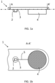
- Figs. 1a and 1b show a known solution for a signal acquisition device 1 comprising an electrode 4 and an amplifier 2.
- the amplifier is mechanically shielded by a shield 3 to avoid its damage from mechanical loads and to avoid skin irritation or direct electrical contact with the skin.
- Shield 3 may be a casing or potting compounds e.g., based on epoxy.
- Conductor 5 is the wire or track connecting the output of the electrode 4 with the input of the amplifier 3.
- Conductor 5 is sensitive to electromagnetic interference, thus it needs to be shielded, to maintain the desired signal quality, expressed for example by a metric such as signal to noise ratio. The longer the distance between the amplifier 3 and the electrode 4, the longer conductor 5 is and the more the signal degrades due to electromagnetic interference.
- the invention proposes to use the electrode itself for protection of the amplifier from mechanical and electrostatic loads. Another advantage is that the length of the conductor is minimized, so that not only interference but also degradation of signal quality due to other reasons, such as resistance, capacitance, and conductance per unit length of the conductor is limited. Embodiments may also provide electromagnetic interference shielding of the conductor connecting the electrode with the amplifier.
- the electrode used for acquiring the signals of the subject comprises a cavity, which cavity has the required dimensions to house the amplifier.
- the cavity of the electrode may for example have a diameter of up to 10 mm, but a greater diameter may be used according to the dimensions of the used amplifier and/or electrode.
- the thickness of the electrode in its part that does not comprise the cavity may be the thickness of commonly used electrodes, but it may also be thicker, e.g., up to 3 mm thicker. A thicker electrode may permit a better skin contact. Nevertheless, when applied on the skin, the part of the electrode that is not in contact with the skin is susceptible to electromagnetic interference. Thus, the thickness of the electrode is preferably chosen in such a manner, that when the electrode is positioned on a user, the part of the electrode not in contact with the skin is minimized.
- the gist of the invention is that it is the electrode itself that comprises the cavity where the amplifier is housed.
- a signal acquisition device which comprises an enclosure, an electrode, an amplifier and possibly other components, wherein the enclosure and not the electrode has a cavity for housing the amplifier.
- a signal acquisition device 10 comprises an electrode 40 for acquiring a signal from a subject and an amplifier 20 configured to amplify the signal acquired by electrode 40.
- Electrode 40 comprises a cavity 60 wherein the amplifier 20 is housed.
- the cavity 60 in Fig. 2a is shown to have an opening opposite to the part of the electrode configured to be in contact with the subject or the subject's clothes, nevertheless, the cavity may have an opening in any part of the electrode, including the part configured to be in contact with the subject.
- Fig. 2b is a rotated view of Fig 2a .
- a conductor 50 is shown, which connects the electrode 40 to the amplifier 20.
- the conductor 50 delivers the signal acquired by electrode 40 to amplifier 20.
- the conductor 50 may at least be partially housed within the electrode, which thus provides protection from electromagnetic interference. As the amplifier is also housed within the electrode, the conductor length is kept to a minimum.
- the signal acquisition device may be configured to be mounted on a substrate, e.g. a circuit board such as a PCB or a flexible circuit, as shown with dashed lines for example in Figs. 2a, 2b , 4a and 4b .
- a substrate e.g. a circuit board such as a PCB or a flexible circuit, as shown with dashed lines for example in Figs. 2a, 2b , 4a and 4b .
- Fig. 3 shows another embodiment of the signal acquisition device 10.
- the electrode 40 substantially surrounds the amplifier 20.
- the cavity 60 may have an opening 70 for the output of the amplifier 20 to exit the cavity 60 of electrode 40.
- the opening 70 may enable a part of a circuit board to have access to cavity 60.
- the electrode may comprise 2 parts, 40a and 40b, which when assembled form electrode 40.
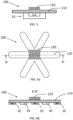
- Figs. 4a and 4b show another embodiment of the signal acquisition device 10.
- the signal acquisition device 10 comprises an electrode 40 and an amplifier 20 configured to amplify the signal acquired by electrode 40 and carried by conductor 50 from the electrode 40 to the amplifier 20.
- Electrode 40 comprises a cavity 60 wherein the amplifier 20 is housed.
- the cavity 60 is shown to have an opening 70 opposite to the part of the electrode configured to be in contact with the subject or the subject's clothes, nevertheless, the cavity may have an opening in any part of the electrode, including the part configured to be in contact with the subject.
- a track 80 is connected to the output of the amplifier 20 and is configured to carry the amplified signal of the amplifier 20.
- the track 80 is also connected to a conductive element 90.
- the conductive element 90 may be directly connected to the output of the amplifier 20.
- the conductive element 90 may not be connected to the output of the amplifier, but it may carry a controlled voltage from another source, e.g., it may be connected to ground, or a power source.
- the voltage source has a low output impedance, and the voltage has minimal fluctuations.
- the conductive element 90 is positioned across an opening 70 of the cavity 60.
- the conductive element 90 is exemplary shown to be disc shaped fully covering opening 70. Nevertheless, the conductive element 90 may have any shape, regular or irregular and it may partially cover the electrode 40 or an opening 70 of the cavity 60.
- the conductive element 90 may comprise a peripheral element 95, positioned in the periphery of conductive element 90 as shown in Fig. 4a . Purpose of peripheral element 95 is to provide electromagnetic interference protection from a wider range of angles.
- Conductive element 90 at least partially covers conductor 50.
- conductor 50 connecting the electrode with an input of the amplifier is at least partially shielded from interference.
- the conductive element 90 forms an interference shield configured to shield the conductor 50 from electromagnetic interference.
- the conductive element 90 carries a controlled voltage having minimal fluctuations, from a low-impedance source, e.g., 0 V or voltage of a power source, passive shielding of the conductor 50 is achieved.
- a voltage with minimal fluctuations may only cause minimal dynamic distortion.
- a significant voltage difference can occur between the conductive element 90 acting as a shield and the electrode 40.
- the distance between the shield i.e., conductive element 90 and electrode 40 varies, e.g. due to mechanical stress, the shifting of electrical loads could cause disturbances, due to the microphonic effect.
- An advantage of the proposed signal acquisition device 10 comprising a conductive element 90 is that due to the rigidness of the signal acquisition device 10, the distance of conductive element 90 from the electrode 40, remains unchanged or changes minimally, in case the signal acquisition device is used, or in case it is under mechanical loads. As a result, electrical noise caused by a microphonic effect is also minimized.
- the conductive element 90 is connected to the output of the amplifier 20, it carries a controlled voltage, which is the amplified or buffered signal, and active shielding of conductor 50 is thus achieved. In this case there is no significant voltage difference between the conductive element 90 acting as a shield and the electrode 40 and therefore no disturbances causing electrical noise.
- the conductive element 90 is thus to strengthen the protection of conductor 50 from interference as already described with regard to Figs. 2a and 2b . It is not necessary that the conductive element 90 is in contact with the electrode 40.
- the conductive element 90 is included in a circuit board 110 and the electrode 40 is mounted on the circuit board 110 in such a way, that the conductive element 90 is positioned across an opening 70 of the cavity 60 of electrode 40.
- a wearable patch 100 comprises the signal acquisition device 10 as has already been described herein.
- the wearable patch can be used for monitoring biometric parameters of a subject, e.g. based on an electrocardiogram, electrooculogram, electromyogram, electroencephalogram or an electrical-cardiotocogram.
- Fig. 5 shows an example of such a wearable patch 100 comprising a signal acquisition device 10.
- the wearable patch 100 may comprise a circuit board 110, e.g. a PCB or a flexible circuit.
- the wearable patch 100 may also comprise an electronics module 120, having all necessary submodules, enabling it to receive the amplified signal from the signal acquisition device 10.
- the electronics module may comprise any of a power source, a connection to a power source, a transmitter, a receiver, a CPU, a controller, a memory, and an amplifier.
- the electronics module 120 receives the output of the signal acquisition device which is the amplified signal acquired by electrode 40.
- the amplified signal may be amplified by a second amplifier of the electronics module 120.
- the electronics module may process the signal and transmit the processed signal to an external device like a monitor, a database or a monitoring device such as a patient monitor.
- the electronics module may alternatively not process the signal and it may directly transmit it to another device to be stored or processed.
- Figs. 6a and 6b show another example of a wearable patch 100 comprising a plurality of signal acquisition devices 10.
- the wearable patch 100 may comprise electrodes 45 which do not house an amplifier 20.
- Electrodes 45 may be electrodes as already known in the state of the art. They may be used as ground electrodes, for common mode rejection, preventing power line noise from interfering with the biopotential signals of interest.
- the invention provides a signal acquisition device 10 comprising an electrode 40 for acquiring a signal from a subject, and an amplifier 20 being configured to amplify or buffer the signal from the electrode, wherein the signal acquisition device comprises a cavity 60 housing the amplifier.
- the electrode comprises the cavity housing the amplifier. The cavity within the electrode provides mechanical and electrostatic shielding to the amplifier.
Landscapes
- Life Sciences & Earth Sciences (AREA)
- Health & Medical Sciences (AREA)
- Medical Informatics (AREA)
- Biophysics (AREA)
- Pathology (AREA)
- Engineering & Computer Science (AREA)
- Biomedical Technology (AREA)
- Heart & Thoracic Surgery (AREA)
- Physics & Mathematics (AREA)
- Molecular Biology (AREA)
- Surgery (AREA)
- Animal Behavior & Ethology (AREA)
- General Health & Medical Sciences (AREA)
- Public Health (AREA)
- Veterinary Medicine (AREA)
- Measurement And Recording Of Electrical Phenomena And Electrical Characteristics Of The Living Body (AREA)
Priority Applications (1)
| Application Number | Priority Date | Filing Date | Title |
|---|---|---|---|
| EP22190906.2A EP4324400A1 (de) | 2022-08-18 | 2022-08-18 | Signalerfassungsvorrichtung |
Applications Claiming Priority (1)
| Application Number | Priority Date | Filing Date | Title |
|---|---|---|---|
| EP22190906.2A EP4324400A1 (de) | 2022-08-18 | 2022-08-18 | Signalerfassungsvorrichtung |
Publications (1)
| Publication Number | Publication Date |
|---|---|
| EP4324400A1 true EP4324400A1 (de) | 2024-02-21 |
Family
ID=83507527
Family Applications (1)
| Application Number | Title | Priority Date | Filing Date |
|---|---|---|---|
| EP22190906.2A Withdrawn EP4324400A1 (de) | 2022-08-18 | 2022-08-18 | Signalerfassungsvorrichtung |
Country Status (1)
| Country | Link |
|---|---|
| EP (1) | EP4324400A1 (de) |
Citations (2)
| Publication number | Priority date | Publication date | Assignee | Title |
|---|---|---|---|---|
| US20090018429A1 (en) * | 2007-07-13 | 2009-01-15 | Cleveland Medical Devices | Method and system for acquiring biosignals in the presence of HF interference |
| US20170105646A1 (en) * | 2014-06-26 | 2017-04-20 | Biopeak Corporation | Multi-parameter sensor system for measuring physiological signals |
-
2022
- 2022-08-18 EP EP22190906.2A patent/EP4324400A1/de not_active Withdrawn
Patent Citations (2)
| Publication number | Priority date | Publication date | Assignee | Title |
|---|---|---|---|---|
| US20090018429A1 (en) * | 2007-07-13 | 2009-01-15 | Cleveland Medical Devices | Method and system for acquiring biosignals in the presence of HF interference |
| US20170105646A1 (en) * | 2014-06-26 | 2017-04-20 | Biopeak Corporation | Multi-parameter sensor system for measuring physiological signals |
Non-Patent Citations (2)
| Title |
|---|
| GORDON PAUL: "Screen printed textile based wearable biopotential monitoring", THESIS SUBMITTED IN PARTIAL FULFILMENT FOR THE DEGREE OF DOCTOR OF PHILOSOPHY, 16 July 2014 (2014-07-16), pages 1 - 236, XP055940555, Retrieved from the Internet <URL:https://eprints.soton.ac.uk/374177/1/__soton.ac.uk_ude_personalfiles_users_jo1d13_mydesktop_GP-Thesis-Final.pdf> [retrieved on 20220711] * |
| TAKESHITA TOSHIHIRO ET AL: "Cubic Flocked Electrode Embedding Amplifier Circuit for Smart ECG Textile Application", 2019 20TH INTERNATIONAL CONFERENCE ON SOLID-STATE SENSORS, ACTUATORS AND MICROSYSTEMS & EUROSENSORS XXXIII (TRANSDUCERS & EUROSENSORS XXXIII), IEEE, 23 June 2019 (2019-06-23), pages 2189 - 2192, XP033600409, DOI: 10.1109/TRANSDUCERS.2019.8808816 * |
Similar Documents
| Publication | Publication Date | Title |
|---|---|---|
| US5355883A (en) | Electrode connector, in particular for electrocardiogram electrodes, and electrode assembly comprising a connector of this kind | |
| US20190365318A1 (en) | Shielding techniques for noise reduction in surface electromyography signal measurement and related systems and methods | |
| US20110166434A1 (en) | System for sensing electrophysiological signals | |
| CA2846338C (en) | Eeg monitor with capacitive electrodes and method of monitoring brain waves | |
| US20110004089A1 (en) | Ear-worn eeg monitoring device | |
| US9775531B2 (en) | Sensor device, processing device, and measurement system for acquiring a biopotential | |
| US20050215916A1 (en) | Active, multiplexed digital electrodes for EEG, ECG and EMG applications | |
| US20070270678A1 (en) | Wireless Electrode for Biopotential Measurement | |
| US4640290A (en) | Shielded, self-preparing electrode suitable for electroencephalographic mapping | |
| US20100016701A1 (en) | Flexible electrode assembly and apparatus for measuring electrophysiological signals | |
| KR20180056671A (ko) | 생체 전기 신호를 검출하기 위한 외이도 플러그 | |
| US4503860A (en) | Electroencephalography electrode assembly | |
| US11931175B2 (en) | In-ear and around-the-ear electroencephalography system with floating electrodes and method thereof | |
| US12433501B2 (en) | Sensor circuit device for measuring a bio-potential or a bio-impedance | |
| US20180132717A1 (en) | ECG Electrode and Method for Detecting an ECG Measurement Signal | |
| EP4324400A1 (de) | Signalerfassungsvorrichtung | |
| JP2004249107A (ja) | 患者監視システム | |
| Hazrati et al. | Wireless brain signal recordings based on capacitive electrodes | |
| CN219183789U (zh) | 脑电信号采集装置 | |
| RU2718662C1 (ru) | Бесконтактный датчик и устройство регистрации биоэлектрической активности головного мозга | |
| KR101043971B1 (ko) | Mri 촬영시 전기생리학적 신호를 완충하는 방법 및 장치 | |
| US20240057966A1 (en) | Electronic device | |
| KR102588508B1 (ko) | 능동 전자기 차폐를 적용한 근거리 비접촉식 능동 생체 전극 | |
| WO2023106160A1 (ja) | 生体信号検出装置 | |
| NL2004856C2 (en) | Sensor device, processing device, and measurement system for acquiring a biopotential. |
Legal Events
| Date | Code | Title | Description |
|---|---|---|---|
| PUAI | Public reference made under article 153(3) epc to a published international application that has entered the european phase |
Free format text: ORIGINAL CODE: 0009012 |
|
| STAA | Information on the status of an ep patent application or granted ep patent |
Free format text: STATUS: THE APPLICATION HAS BEEN PUBLISHED |
|
| AK | Designated contracting states |
Kind code of ref document: A1 Designated state(s): AL AT BE BG CH CY CZ DE DK EE ES FI FR GB GR HR HU IE IS IT LI LT LU LV MC MK MT NL NO PL PT RO RS SE SI SK SM TR |
|
| STAA | Information on the status of an ep patent application or granted ep patent |
Free format text: STATUS: THE APPLICATION IS DEEMED TO BE WITHDRAWN |
|
| 18D | Application deemed to be withdrawn |
Effective date: 20240822 |