EP4324663A1 - Bandage pneumatique pour véhicule - Google Patents
Bandage pneumatique pour véhicule Download PDFInfo
- Publication number
- EP4324663A1 EP4324663A1 EP23189562.4A EP23189562A EP4324663A1 EP 4324663 A1 EP4324663 A1 EP 4324663A1 EP 23189562 A EP23189562 A EP 23189562A EP 4324663 A1 EP4324663 A1 EP 4324663A1
- Authority
- EP
- European Patent Office
- Prior art keywords
- incision
- section
- width
- pneumatic vehicle
- central
- Prior art date
- Legal status (The legal status is an assumption and is not a legal conclusion. Google has not performed a legal analysis and makes no representation as to the accuracy of the status listed.)
- Granted
Links
Images

Classifications
-
- B—PERFORMING OPERATIONS; TRANSPORTING
- B60—VEHICLES IN GENERAL
- B60C—VEHICLE TYRES; TYRE INFLATION; TYRE CHANGING; CONNECTING VALVES TO INFLATABLE ELASTIC BODIES IN GENERAL; DEVICES OR ARRANGEMENTS RELATED TO TYRES
- B60C11/00—Tyre tread bands; Tread patterns; Anti-skid inserts
- B60C11/03—Tread patterns
- B60C11/11—Tread patterns in which the raised area of the pattern consists only of isolated elements, e.g. blocks
-
- B—PERFORMING OPERATIONS; TRANSPORTING
- B60—VEHICLES IN GENERAL
- B60C—VEHICLE TYRES; TYRE INFLATION; TYRE CHANGING; CONNECTING VALVES TO INFLATABLE ELASTIC BODIES IN GENERAL; DEVICES OR ARRANGEMENTS RELATED TO TYRES
- B60C11/00—Tyre tread bands; Tread patterns; Anti-skid inserts
- B60C11/03—Tread patterns
- B60C11/12—Tread patterns characterised by the use of narrow slits or incisions, e.g. sipes
- B60C11/1204—Tread patterns characterised by the use of narrow slits or incisions, e.g. sipes with special shape of the sipe
- B60C11/1218—Three-dimensional shape with regard to depth and extending direction
-
- B—PERFORMING OPERATIONS; TRANSPORTING
- B60—VEHICLES IN GENERAL
- B60C—VEHICLE TYRES; TYRE INFLATION; TYRE CHANGING; CONNECTING VALVES TO INFLATABLE ELASTIC BODIES IN GENERAL; DEVICES OR ARRANGEMENTS RELATED TO TYRES
- B60C11/00—Tyre tread bands; Tread patterns; Anti-skid inserts
- B60C11/03—Tread patterns
- B60C11/12—Tread patterns characterised by the use of narrow slits or incisions, e.g. sipes
- B60C11/1259—Depth of the sipe
-
- B—PERFORMING OPERATIONS; TRANSPORTING
- B60—VEHICLES IN GENERAL
- B60C—VEHICLE TYRES; TYRE INFLATION; TYRE CHANGING; CONNECTING VALVES TO INFLATABLE ELASTIC BODIES IN GENERAL; DEVICES OR ARRANGEMENTS RELATED TO TYRES
- B60C11/00—Tyre tread bands; Tread patterns; Anti-skid inserts
- B60C11/03—Tread patterns
- B60C11/12—Tread patterns characterised by the use of narrow slits or incisions, e.g. sipes
- B60C11/1272—Width of the sipe
- B60C11/1281—Width of the sipe different within the same sipe, i.e. enlarged width portion at sipe bottom or along its length
-
- B—PERFORMING OPERATIONS; TRANSPORTING
- B60—VEHICLES IN GENERAL
- B60C—VEHICLE TYRES; TYRE INFLATION; TYRE CHANGING; CONNECTING VALVES TO INFLATABLE ELASTIC BODIES IN GENERAL; DEVICES OR ARRANGEMENTS RELATED TO TYRES
- B60C11/00—Tyre tread bands; Tread patterns; Anti-skid inserts
- B60C11/03—Tread patterns
- B60C11/12—Tread patterns characterised by the use of narrow slits or incisions, e.g. sipes
- B60C11/1204—Tread patterns characterised by the use of narrow slits or incisions, e.g. sipes with special shape of the sipe
- B60C2011/1209—Tread patterns characterised by the use of narrow slits or incisions, e.g. sipes with special shape of the sipe straight at the tread surface
Definitions
- the invention relates to a pneumatic vehicle tire with a tread with tread blocks and/or with at least one profile rib running in the circumferential direction, in which or in which, in plan view, incisions are formed which run at an angle of 0° to 50° to the axial direction and each have two incision walls are, wherein each incision extends to its maximum depth of 70% to 100% of the profile depth at least in an incision area extending over part of the incision in plan view, the incision in this incision area, viewed in cross section, having a straight, radially outer incision section a width of 0.6 mm to 2.0 mm, an arcuate central incision section adjoining this and forming a bulge and a channel-shaped, radially inner incision section extending to the maximum depth with a maximum width of 150% to 400% the width of the radially outer incision section.
- Such a pneumatic vehicle tire which is preferably a commercial vehicle tire, is, for example, from EP 3 414 112 B1 known.
- the tread of the tire has middle tread block rows with tread blocks, each with an incision running in plan view to the axial direction at an angle of 0° to 50° with a maximum depth of up to 100% of the tread depth.
- the incision is composed of an elongated Z-shaped central incision area and two straight edge incision areas.
- the incision In the edge-side incision areas, viewed in cross section, the incision has a straight, radially outer incision section, two central incision sections which each form a bulge, are arcuate in cross section, and a channel-shaped, radially inner incision section which extends to the maximum depth and is rounded outwards Wall sections.
- the radially outer incision section and the middle incision sections have a consistent width of 0.6 mm to 3.0 mm, with the entire incision preferably having a constant width.
- the width of the radially outer incision section and each central incision section is 0.6 mm and the maximum width of the radially inner incision section is 2.2 mm, 2.8 mm or 3.2 mm. With a maximum width of the radially inner incision section of 2.2 mm, this is therefore approximately 367% of the width of the radially outer incision section.
- the cuts should have good water and snow absorption capacity and be beneficial for the traction behavior of the tire.
- incisions with channel-shaped, radially inner incision sections a concentration of stresses and shear forces in the radially inner incision section is avoided or largely avoided, which is advantageous for the crack resistance of the adjacent rubber material.
- these incision sections reduce the rigidity of the adjacent profile positive segments - compared to incisions with a conventional incision base - so that they are deformed to a greater extent under load, which is unfavorable in terms of braking performance.
- the central incision section which forms a bulge and has an arcuate cross-section, is advantageous for the mutual support of the profile segments under load, but does not sufficiently compensate for the disadvantages of the channel-shaped, radially inner incision section with regard to braking performance.
- the invention is therefore based on the object of improving the braking performance of a pneumatic vehicle tire of the type mentioned, especially on dry roads.
- the arcuate, central incision section has a width which is at least is 0.2 mm and is at least 0.2 mm smaller than the width of the radially outer incision section.
- the width of the central incision section is at least 0.4 mm.
- the width of the central incision section is at least 0.4 mm, in particular at least 0.6 mm, preferably at least 0.8 mm, particularly preferably at least 1.0 mm smaller than the width of the radially outer one incision section.
- the central incision section viewed in cross section, runs along an arc of a circle.
- a further preferred embodiment is characterized in that the central incision section has a length, determined in the radial direction, of 10% to 50%, in particular 20% to 40%, of the maximum depth of the incision. This promotes the support effects mentioned, which further improves braking performance.
- the central incision section has a plane of symmetry which is in a radial direction Direction determined constant depth of 25% to 60%, in particular up to 50%, of the maximum depth of the incision.
- the support effects are further improved if the central incision section, viewed in cross section, has a maximum deflection, which is determined perpendicular to a reference line which runs in a straight line extension of the incision center surface in the area of the radially outer incision section and is 0.5 mm to 1.5 mm is.
- a further preferred embodiment is characterized in that the tread is designed to be directional, so that the incision has an incoming incision edge which first enters the ground when the tire rolls forward while driving forward, and an outgoing incision edge, the arcuate, central incision section being designed in such a way that that a projection is formed on the incision wall extending from the incoming incision edge and a recess corresponding to the projection is formed on the incision wall extending from the outgoing incision edge.
- this orientation of the arcuate, central incision section is advantageous because the bulge is directed in the direction of the so-called braking edge of the profile block, which ensures particularly favorable support effects with regard to the braking properties.
- the radially outer incision section has a length of 5% to 40%, in particular 20% to 30%, of the maximum depth of the incision, based on the center area of the incision and determined in the radial direction. Consequently, the arcuate, central incision section is correspondingly spaced from the tread periphery, which is of further advantage for supporting effects.
- the maximum width of the radially inner incision section is 200% to 350% of the width of the radially outer incision section.
- this contributes to the fact that the rigidity of the adjacent profile positive segments is reduced to a correspondingly limited extent, which is also beneficial for braking performance.
- a further preferred embodiment is characterized in that the radially inner incision section, viewed in cross section, is pear-shaped or teardrop-shaped and is delimited by radially inner wall sections of the incision walls, the radially inner wall sections adjoining one another tangentially at the maximum depth.
- an advantageous embodiment of the last-mentioned preferred embodiment is that the radially inner incision section has a plane of symmetry that coincides with the incision center surface.
- the radially inner incision section viewed in cross section, has a length of 10% to 30%, in particular 15% to 25%, of the maximum depth of the incision, based on the plane of symmetry.
- the incision viewed in cross section, in the incision area reaching the maximum depth consists of the radially outer incision section, the arcuate, central incision section, a straight-running section adjoining the radially inner end of the arcuate, central incision section. second central incision section and the radially inner incision section together.
- An advantageous embodiment of the last-mentioned preferred embodiment is characterized in that the second central incision section has a width of 0.6 mm to 2.0 mm, in particular up to 1.6 mm, and preferably up to 1.2 mm, wherein the width of the second central incision section preferably corresponds to the width of the radially outer incision section.
- Pneumatic vehicle tires designed according to the invention are tires for motor vehicles, in particular for multi-lane motor vehicles, and preferably tires of radial design for passenger cars, vans or light trucks (light trucks with GVW ⁇ 7.5 t).
- Fig. 1 shows a top view of a middle tread block 1, which belongs to a tread of a pneumatic vehicle tire.
- the tread has a plurality of tread blocks 1 and is designed to be directional in a manner not shown, with the pneumatic vehicle tire being mounted on a vehicle, such as a car, in such a way that it has the rolling direction symbolized by the arrow R when driving forward.
- the profile block 1 is laterally through in Fig. 1 only indicated circumferential grooves 2 and limited by transverse grooves 3 running between the circumferential grooves 2 and also only indicated.
- the circumferential grooves 2 and preferably also the transverse grooves 3 are in the radial direction to the tread depth T P (indicated in.) intended for the respective pneumatic vehicle tire Fig. 2 ), which is usually 6.5 mm to 12.0 mm, in particular 7.0 mm to 9.5 mm, for the preferred tire type mentioned (car, van, light truck).
- the tread block 1 has an outer block surface 4 on the tread periphery and, based on its circumferential extent, is provided in its central region with an incision 5 that starts from the outer block surface 4, projects into the radial interior of the tread block 1 and traverses the tread block 1 (see Fig. Fig. 2 ).
- the incision 5 When viewed in plan view, the incision 5 runs straight and at an angle ⁇ of 0° to 50°, in particular of 5° to 25°, to the axial direction.
- the incision 5 has on the outer block surface 4 an incoming incision edge 6a which first enters the ground when the tire rolls forward (arrow R) and an outgoing incision edge 6b, with points lying on the incoming incision edge 6a when the tire rolls off while driving forward enter the subsurface in front of the point exactly opposite in the circumferential direction and lying on the tapering cut edge 6b.
- the incision 5 has an incision wall 7a starting from the incoming incision edge 6a, an incision wall 7b starting from the outgoing incision edge 6b, an incision center line m E following the course of the incision in plan view ( Fig. 1 ), an incision center surface f E ( Fig. 2 ), a length c E determined at the tread periphery along the cut center line m E ( Fig. 1 ) and a maximum depth t E (determined in the radial direction) over the entire length c E ( Fig. 2 , depth at the deepest point).
- the maximum depth t E is 70% to 100% of the tread depth T P ( Fig. 2 ), preferably at most the profile depth T P reduced by 0.5 mm ( Fig. 2 ).
- the incision 5 is located, viewed in the top view perpendicular to the incision center line m E (see position of line II-II in Fig. 1 ), from a radially outer one running in the radial direction Incision section 5a, a first central incision section 5b, a second central incision section 5c running in the radial direction and a radially inner incision section 5d.
- incision sections 5a, 5b, 5c, 5d refers to the cross section oriented perpendicular to the incision center line m E in plan view, as in Fig. 2 shown (compare position of line II-II in Fig. 1 ).
- the radially outer incision section 5a has a constant width b a of 0.6 mm to 2.0 mm, in particular up to 1.6 mm, and preferably up to 1.2 mm, determined perpendicular to the incision center surface f E , and a the length c a of 5% to 40%, in particular 20% to 30%, of the maximum depth t E , relative to the incision center surface f E and determined in the radial direction.
- the second central incision section 5c runs in continuation to the radially outer incision section 5a and has a constant width b c of 0.6 mm to 2.0 mm, in particular of up to 1.6 mm, and preferably of up to, determined perpendicular to the incision center surface f E to 1.2 mm, whereby the width b c preferably corresponds to the width b a .
- the first central incision section 5b runs in an arc, in particular along an arc of a circle, forms a bulge, has a length c b , determined in the radial direction, of 10% to 50%, in particular 20% to 40%, of the maximum, relative to the incision center surface f E Depth t E , a constant width b b determined perpendicular to the incision center surface f E and a plane of symmetry E 1 running in a constant depth t E1 determined in the radial direction. With regard to the plane of symmetry E 1 , the tire curvature is not taken into account.
- the width b b is at least 0.2 mm, preferably at least 0.4 mm, and is at least 0.2 mm, in particular at least 0.4 mm, preferably at least 0.6 mm, particularly preferably at least 0.8 mm, and most preferably at least 1.0 mm smaller than the width b a of the radially outer incision section 5a.
- the lengths c a , c b are preferably coordinated with one another in such a way that the depth t E1 is 25% to 60%, in particular up to 50%, of the maximum depth t E.
- a straight reference line L 1 is shown connecting the central incision surface f E between the radially outer incision section 5a and the second central incision section 5c.
- the first central incision section 5b has a maximum deflection a of 0.5 mm to 1.5 mm in the plane of symmetry E 1 between the reference line L 1 and the incision center surface f E.
- the first middle incision section 5b is further designed in such a way that a circular segment-shaped projection 8 is formed on the incision wall 7a extending from the incoming incision edge 6a and a recess 9 corresponding to the projection 8 is formed on the incision wall 7b extending from the outgoing incision edge 6b.
- “Corresponding” means that the constant width b b already mentioned is present in the first central incision section 5b.
- the recess 9 projects into the incision wall 7b relative to the level of the incision wall 7b present in the area of the incision sections 5a, 5c and the projection 8 projects from the incision wall 7a in relation to the level of the incision wall 7a present in the area of the incision sections 5a, 5c.
- the radially inner incision section 5d has a plane of symmetry E 2 that runs in the radial direction and coincides with the center surface of the incision f E , is pear-shaped or teardrop-shaped, and has a length c determined in the radial direction and related to the center surface of the incision f E or the plane of symmetry E 2 d from 10% to 30%, in particular from 15% to 25%, of the maximum depth t E as well as a maximum width b d (width at the widest) determined parallel to the tread periphery, therefore perpendicular to the center surface of the cut f E or the plane of symmetry E 2 Position) from 150% to 400%, in particular from 200% to 350%, of the width b a of the radially outer incision section 5a and is limited by a radially inner wall section 7b 'of the incision wall 7b and a radially inner wall section 7a' of the incision wall 7a .
- the radial Inner wall sections 7a', 7b' adjoin one another tangentially at the maximum depth t E and, starting from this, curve outwards over the majority of the length c d .
- a “teardrop shape” is understood to mean a ball that tapers to a point on one side.
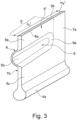
- Fig. 3 shows a visualization of an incision 5 ', which is a variant of the incision 5.
- the incision 5 l has an incision center line m E 'on the tread periphery and a length c E l determined along the incision center line m E l .
- the incision 5l has all of the described incision sections 5a, 5b, 5c, 5d exclusively in an incision area 5' which opens into a circumferential groove (not shown), which, viewed in plan view, preferably extends over at least the majority of the length c E l .
- the incision section 5b has a projection 8 (not visible, but implicitly recognizable) which is formed on the incision wall 7a starting from the incoming incision edge 6a and is formed on the incision wall 7b which extends from the incoming incision edge 6b and which corresponds to the projection 8 9 (not visible, but implicitly recognizable).
- the design of the incision section 5b is preferably such that the projection 8 has a semicircular projection part 8a at its end facing away from the circumferential groove, on the inside of the incision when viewed from the incision wall 5a.
- the radially inner incision section 5d runs over the entire length c E l .
- the incisions can be formed in middle or shoulder-side profile blocks as well as in middle or shoulder-side profile ribs running circumferentially.
- the incisions each have the incision sections at least in an incision area that extends over part of the incision in a plan view, which in plan view preferably runs at least over the majority of the respective incision, i.e. extends over more than 50% of the length of the incision.
- the incisions can each have more than one incision section which is arcuate in cross section and forms a bulge, the incisions each having in particular two or three of these incision sections.
- Rounded transition sections can be formed between the individual incision sections, which, viewed in the cross section running perpendicular to the incision center line in plan view and in relation to the incision center surface, ensure a tangential (kink-free) transition between the incision sections.
- the incisions can each have one edge-side incision area raised in the radial direction or two edge-side incision areas raised in the radial direction.
- the incisions when viewed in plan view, can be wavy at least in sections, for example in the form of a curved wave, a zigzag wave or a sawtooth wave, and/or curved (arc-shaped) overall.
- the angle at which the incisions run in relation to the axial direction refers to a straight line which is drawn between the ends of the incision center line that follows the course of the incision and is therefore curved and/or wavy .
- the tread does not have to be directional.
Landscapes
- Engineering & Computer Science (AREA)
- Mechanical Engineering (AREA)
- Tires In General (AREA)
Applications Claiming Priority (1)
| Application Number | Priority Date | Filing Date | Title |
|---|---|---|---|
| DE102022208619.8A DE102022208619A1 (de) | 2022-08-19 | 2022-08-19 | Fahrzeugluftreifen |
Publications (2)
| Publication Number | Publication Date |
|---|---|
| EP4324663A1 true EP4324663A1 (fr) | 2024-02-21 |
| EP4324663B1 EP4324663B1 (fr) | 2025-12-31 |
Family
ID=87556063
Family Applications (1)
| Application Number | Title | Priority Date | Filing Date |
|---|---|---|---|
| EP23189562.4A Active EP4324663B1 (fr) | 2022-08-19 | 2023-08-03 | Bandage pneumatique pour véhicule |
Country Status (2)
| Country | Link |
|---|---|
| EP (1) | EP4324663B1 (fr) |
| DE (1) | DE102022208619A1 (fr) |
Families Citing this family (1)
| Publication number | Priority date | Publication date | Assignee | Title |
|---|---|---|---|---|
| DE102024109441A1 (de) * | 2024-04-04 | 2025-10-09 | Continental Reifen Deutschland Gmbh | Fahrzeugreifen |
Citations (6)
| Publication number | Priority date | Publication date | Assignee | Title |
|---|---|---|---|---|
| JP2002316517A (ja) * | 2001-04-24 | 2002-10-29 | Toyo Tire & Rubber Co Ltd | 空気入りタイヤ |
| JP4327962B2 (ja) * | 1999-11-04 | 2009-09-09 | 株式会社ブリヂストン | 空気入りタイヤ |
| EP3414112B1 (fr) | 2016-02-09 | 2020-01-29 | Pirelli Tyre S.p.A. | Pneu pour roues de véhicule |
| US11186054B2 (en) * | 2015-09-30 | 2021-11-30 | Compagnie Generale Des Etablissements Michelin | Variable thickness sipes |
| AU2020275890A1 (en) * | 2019-05-16 | 2021-12-16 | Compagnie Générale Des Etablissements Michelin | Tyre tread for a heavy-duty vehicle of construction plant type |
| WO2023107828A1 (fr) * | 2021-12-06 | 2023-06-15 | Bridgestone Americas Tire Operations, Llc | Combinaison de lamelles et de fentes à verrouillage bidirectionnel |
-
2022
- 2022-08-19 DE DE102022208619.8A patent/DE102022208619A1/de active Pending
-
2023
- 2023-08-03 EP EP23189562.4A patent/EP4324663B1/fr active Active
Patent Citations (6)
| Publication number | Priority date | Publication date | Assignee | Title |
|---|---|---|---|---|
| JP4327962B2 (ja) * | 1999-11-04 | 2009-09-09 | 株式会社ブリヂストン | 空気入りタイヤ |
| JP2002316517A (ja) * | 2001-04-24 | 2002-10-29 | Toyo Tire & Rubber Co Ltd | 空気入りタイヤ |
| US11186054B2 (en) * | 2015-09-30 | 2021-11-30 | Compagnie Generale Des Etablissements Michelin | Variable thickness sipes |
| EP3414112B1 (fr) | 2016-02-09 | 2020-01-29 | Pirelli Tyre S.p.A. | Pneu pour roues de véhicule |
| AU2020275890A1 (en) * | 2019-05-16 | 2021-12-16 | Compagnie Générale Des Etablissements Michelin | Tyre tread for a heavy-duty vehicle of construction plant type |
| WO2023107828A1 (fr) * | 2021-12-06 | 2023-06-15 | Bridgestone Americas Tire Operations, Llc | Combinaison de lamelles et de fentes à verrouillage bidirectionnel |
Also Published As
| Publication number | Publication date |
|---|---|
| DE102022208619A1 (de) | 2024-02-22 |
| EP4324663B1 (fr) | 2025-12-31 |
Similar Documents
| Publication | Publication Date | Title |
|---|---|---|
| EP4244080B1 (fr) | Bandage pneumatique de véhicule | |
| EP3888948B1 (fr) | Pneumatiques de vehicule, en particulier pour un vehicule utilitaire | |
| EP3785938A1 (fr) | Pneumatique de véhicule | |
| EP4221996B1 (fr) | Pneu pour un véhicule | |
| EP4324663A1 (fr) | Bandage pneumatique pour véhicule | |
| WO2018108358A1 (fr) | Pneumatique de véhicule | |
| EP4171972B1 (fr) | Bandage pneumatique de véhicule | |
| EP2138327A1 (fr) | Bande de roulement por pneumatique | |
| EP3441241A1 (fr) | Pneumatique de véhicule | |
| EP3765311B1 (fr) | Pneumatique de véhicule | |
| EP4144542B1 (fr) | Pneumatique de véhicule | |
| EP3551475B1 (fr) | Pneumatique de véhicule | |
| EP2000329B1 (fr) | Bandages pneumatiques | |
| WO2024200185A1 (fr) | Pneumatique de véhicule | |
| EP2138328B1 (fr) | Pneus de véhicule | |
| EP4173847A1 (fr) | Bandage pneumatique pour véhicule | |
| EP4342685B1 (fr) | Bandage pneumatique pour véhicule | |
| EP4385761B1 (fr) | Bandage pneumatique pour véhicule | |
| EP4003760A1 (fr) | Pneumatique de véhicule | |
| EP4491417B1 (fr) | Bandage pneumatique pour véhicules | |
| EP4244079B1 (fr) | Pneumatique de véhicule | |
| EP3715146B1 (fr) | Pneumatique de véhicule | |
| EP4628328A1 (fr) | Bandage pneumatique pour véhicules | |
| DE102024109447A1 (de) | Fahrzeugreifen | |
| WO2025131188A1 (fr) | Pneumatique de véhicule, en particulier pneumatique de véhicule utilitaire |
Legal Events
| Date | Code | Title | Description |
|---|---|---|---|
| PUAI | Public reference made under article 153(3) epc to a published international application that has entered the european phase |
Free format text: ORIGINAL CODE: 0009012 |
|
| STAA | Information on the status of an ep patent application or granted ep patent |
Free format text: STATUS: THE APPLICATION HAS BEEN PUBLISHED |
|
| AK | Designated contracting states |
Kind code of ref document: A1 Designated state(s): AL AT BE BG CH CY CZ DE DK EE ES FI FR GB GR HR HU IE IS IT LI LT LU LV MC ME MK MT NL NO PL PT RO RS SE SI SK SM TR |
|
| RAP3 | Party data changed (applicant data changed or rights of an application transferred) |
Owner name: CONTINENTAL REIFEN DEUTSCHLAND GMBH |
|
| STAA | Information on the status of an ep patent application or granted ep patent |
Free format text: STATUS: REQUEST FOR EXAMINATION WAS MADE |
|
| 17P | Request for examination filed |
Effective date: 20240821 |
|
| RBV | Designated contracting states (corrected) |
Designated state(s): AL AT BE BG CH CY CZ DE DK EE ES FI FR GB GR HR HU IE IS IT LI LT LU LV MC ME MK MT NL NO PL PT RO RS SE SI SK SM TR |
|
| RIC1 | Information provided on ipc code assigned before grant |
Ipc: B60C 11/12 20060101ALI20250512BHEP Ipc: B60C 11/11 20060101AFI20250512BHEP |
|
| GRAP | Despatch of communication of intention to grant a patent |
Free format text: ORIGINAL CODE: EPIDOSNIGR1 |
|
| STAA | Information on the status of an ep patent application or granted ep patent |
Free format text: STATUS: GRANT OF PATENT IS INTENDED |
|
| INTG | Intention to grant announced |
Effective date: 20250623 |
|
| GRAS | Grant fee paid |
Free format text: ORIGINAL CODE: EPIDOSNIGR3 |
|
| GRAA | (expected) grant |
Free format text: ORIGINAL CODE: 0009210 |
|
| STAA | Information on the status of an ep patent application or granted ep patent |
Free format text: STATUS: THE PATENT HAS BEEN GRANTED |
|
| AK | Designated contracting states |
Kind code of ref document: B1 Designated state(s): AL AT BE BG CH CY CZ DE DK EE ES FI FR GB GR HR HU IE IS IT LI LT LU LV MC ME MK MT NL NO PL PT RO RS SE SI SK SM TR |
|
| REG | Reference to a national code |
Ref country code: CH Ref legal event code: F10 Free format text: ST27 STATUS EVENT CODE: U-0-0-F10-F00 (AS PROVIDED BY THE NATIONAL OFFICE) Effective date: 20251231 Ref country code: GB Ref legal event code: FG4D Free format text: NOT ENGLISH |
|
| REG | Reference to a national code |
Ref country code: DE Ref legal event code: R096 Ref document number: 502023002629 Country of ref document: DE |
|
| REG | Reference to a national code |
Ref country code: IE Ref legal event code: FG4D Free format text: LANGUAGE OF EP DOCUMENT: GERMAN |
|
| REG | Reference to a national code |
Ref country code: NL Ref legal event code: FP |
|
| REG | Reference to a national code |
Ref country code: LT Ref legal event code: MG9D |
|
| PG25 | Lapsed in a contracting state [announced via postgrant information from national office to epo] |
Ref country code: NO Free format text: LAPSE BECAUSE OF FAILURE TO SUBMIT A TRANSLATION OF THE DESCRIPTION OR TO PAY THE FEE WITHIN THE PRESCRIBED TIME-LIMIT Effective date: 20260331 |
|
| PG25 | Lapsed in a contracting state [announced via postgrant information from national office to epo] |
Ref country code: FI Free format text: LAPSE BECAUSE OF FAILURE TO SUBMIT A TRANSLATION OF THE DESCRIPTION OR TO PAY THE FEE WITHIN THE PRESCRIBED TIME-LIMIT Effective date: 20251231 Ref country code: HR Free format text: LAPSE BECAUSE OF FAILURE TO SUBMIT A TRANSLATION OF THE DESCRIPTION OR TO PAY THE FEE WITHIN THE PRESCRIBED TIME-LIMIT Effective date: 20251231 |
|
| PG25 | Lapsed in a contracting state [announced via postgrant information from national office to epo] |
Ref country code: RS Free format text: LAPSE BECAUSE OF FAILURE TO SUBMIT A TRANSLATION OF THE DESCRIPTION OR TO PAY THE FEE WITHIN THE PRESCRIBED TIME-LIMIT Effective date: 20260331 |