EP4324689A1 - Procédé de commande de couple et système de commande de couple pour système d'entraînement électrique - Google Patents
Procédé de commande de couple et système de commande de couple pour système d'entraînement électrique Download PDFInfo
- Publication number
- EP4324689A1 EP4324689A1 EP21936286.0A EP21936286A EP4324689A1 EP 4324689 A1 EP4324689 A1 EP 4324689A1 EP 21936286 A EP21936286 A EP 21936286A EP 4324689 A1 EP4324689 A1 EP 4324689A1
- Authority
- EP
- European Patent Office
- Prior art keywords
- voltage
- limit value
- torque
- value
- allowable
- Prior art date
- Legal status (The legal status is an assumption and is not a legal conclusion. Google has not performed a legal analysis and makes no representation as to the accuracy of the status listed.)
- Pending
Links
Images

Classifications
-
- B—PERFORMING OPERATIONS; TRANSPORTING
- B60—VEHICLES IN GENERAL
- B60L—PROPULSION OF ELECTRICALLY-PROPELLED VEHICLES; SUPPLYING ELECTRIC POWER FOR AUXILIARY EQUIPMENT OF ELECTRICALLY-PROPELLED VEHICLES; ELECTRODYNAMIC BRAKE SYSTEMS FOR VEHICLES IN GENERAL; MAGNETIC SUSPENSION OR LEVITATION FOR VEHICLES; MONITORING OPERATING VARIABLES OF ELECTRICALLY-PROPELLED VEHICLES; ELECTRIC SAFETY DEVICES FOR ELECTRICALLY-PROPELLED VEHICLES
- B60L15/00—Methods, circuits, or devices for controlling the traction-motor speed of electrically-propelled vehicles
- B60L15/20—Methods, circuits, or devices for controlling the traction-motor speed of electrically-propelled vehicles for control of the vehicle or its driving motor to achieve a desired performance, e.g. speed, torque, programmed variation of speed
-
- B—PERFORMING OPERATIONS; TRANSPORTING
- B60—VEHICLES IN GENERAL
- B60L—PROPULSION OF ELECTRICALLY-PROPELLED VEHICLES; SUPPLYING ELECTRIC POWER FOR AUXILIARY EQUIPMENT OF ELECTRICALLY-PROPELLED VEHICLES; ELECTRODYNAMIC BRAKE SYSTEMS FOR VEHICLES IN GENERAL; MAGNETIC SUSPENSION OR LEVITATION FOR VEHICLES; MONITORING OPERATING VARIABLES OF ELECTRICALLY-PROPELLED VEHICLES; ELECTRIC SAFETY DEVICES FOR ELECTRICALLY-PROPELLED VEHICLES
- B60L58/00—Methods or circuit arrangements for monitoring or controlling batteries or fuel cells, specially adapted for electric vehicles
- B60L58/10—Methods or circuit arrangements for monitoring or controlling batteries or fuel cells, specially adapted for electric vehicles for monitoring or controlling batteries
- B60L58/12—Methods or circuit arrangements for monitoring or controlling batteries or fuel cells, specially adapted for electric vehicles for monitoring or controlling batteries responding to state of charge [SoC]
- B60L58/14—Preventing excessive discharging
-
- B—PERFORMING OPERATIONS; TRANSPORTING
- B60—VEHICLES IN GENERAL
- B60L—PROPULSION OF ELECTRICALLY-PROPELLED VEHICLES; SUPPLYING ELECTRIC POWER FOR AUXILIARY EQUIPMENT OF ELECTRICALLY-PROPELLED VEHICLES; ELECTRODYNAMIC BRAKE SYSTEMS FOR VEHICLES IN GENERAL; MAGNETIC SUSPENSION OR LEVITATION FOR VEHICLES; MONITORING OPERATING VARIABLES OF ELECTRICALLY-PROPELLED VEHICLES; ELECTRIC SAFETY DEVICES FOR ELECTRICALLY-PROPELLED VEHICLES
- B60L58/00—Methods or circuit arrangements for monitoring or controlling batteries or fuel cells, specially adapted for electric vehicles
- B60L58/10—Methods or circuit arrangements for monitoring or controlling batteries or fuel cells, specially adapted for electric vehicles for monitoring or controlling batteries
- B60L58/12—Methods or circuit arrangements for monitoring or controlling batteries or fuel cells, specially adapted for electric vehicles for monitoring or controlling batteries responding to state of charge [SoC]
- B60L58/15—Preventing overcharging
-
- H—ELECTRICITY
- H02—GENERATION; CONVERSION OR DISTRIBUTION OF ELECTRIC POWER
- H02J—ELECTRIC POWER NETWORKS; CIRCUIT ARRANGEMENTS OR SYSTEMS FOR SUPPLYING OR DISTRIBUTING ELECTRIC POWER; SYSTEMS FOR STORING ELECTRIC ENERGY
- H02J7/00—Circuit arrangements for charging or discharging batteries or for supplying loads from batteries
- H02J7/60—Circuit arrangements for charging or discharging batteries or for supplying loads from batteries including safety or protection arrangements
- H02J7/61—Circuit arrangements for charging or discharging batteries or for supplying loads from batteries including safety or protection arrangements against overcharge
-
- H—ELECTRICITY
- H02—GENERATION; CONVERSION OR DISTRIBUTION OF ELECTRIC POWER
- H02J—ELECTRIC POWER NETWORKS; CIRCUIT ARRANGEMENTS OR SYSTEMS FOR SUPPLYING OR DISTRIBUTING ELECTRIC POWER; SYSTEMS FOR STORING ELECTRIC ENERGY
- H02J7/00—Circuit arrangements for charging or discharging batteries or for supplying loads from batteries
- H02J7/60—Circuit arrangements for charging or discharging batteries or for supplying loads from batteries including safety or protection arrangements
- H02J7/63—Circuit arrangements for charging or discharging batteries or for supplying loads from batteries including safety or protection arrangements against overdischarge
-
- H—ELECTRICITY
- H02—GENERATION; CONVERSION OR DISTRIBUTION OF ELECTRIC POWER
- H02J—ELECTRIC POWER NETWORKS; CIRCUIT ARRANGEMENTS OR SYSTEMS FOR SUPPLYING OR DISTRIBUTING ELECTRIC POWER; SYSTEMS FOR STORING ELECTRIC ENERGY
- H02J7/00—Circuit arrangements for charging or discharging batteries or for supplying loads from batteries
- H02J7/90—Regulation of charging or discharging current or voltage
- H02J7/96—Regulation of charging or discharging current or voltage in response to battery voltage
-
- B—PERFORMING OPERATIONS; TRANSPORTING
- B60—VEHICLES IN GENERAL
- B60L—PROPULSION OF ELECTRICALLY-PROPELLED VEHICLES; SUPPLYING ELECTRIC POWER FOR AUXILIARY EQUIPMENT OF ELECTRICALLY-PROPELLED VEHICLES; ELECTRODYNAMIC BRAKE SYSTEMS FOR VEHICLES IN GENERAL; MAGNETIC SUSPENSION OR LEVITATION FOR VEHICLES; MONITORING OPERATING VARIABLES OF ELECTRICALLY-PROPELLED VEHICLES; ELECTRIC SAFETY DEVICES FOR ELECTRICALLY-PROPELLED VEHICLES
- B60L2240/00—Control parameters of input or output; Target parameters
- B60L2240/40—Drive Train control parameters
- B60L2240/42—Drive Train control parameters related to electric machines
- B60L2240/423—Torque
-
- B—PERFORMING OPERATIONS; TRANSPORTING
- B60—VEHICLES IN GENERAL
- B60L—PROPULSION OF ELECTRICALLY-PROPELLED VEHICLES; SUPPLYING ELECTRIC POWER FOR AUXILIARY EQUIPMENT OF ELECTRICALLY-PROPELLED VEHICLES; ELECTRODYNAMIC BRAKE SYSTEMS FOR VEHICLES IN GENERAL; MAGNETIC SUSPENSION OR LEVITATION FOR VEHICLES; MONITORING OPERATING VARIABLES OF ELECTRICALLY-PROPELLED VEHICLES; ELECTRIC SAFETY DEVICES FOR ELECTRICALLY-PROPELLED VEHICLES
- B60L2240/00—Control parameters of input or output; Target parameters
- B60L2240/40—Drive Train control parameters
- B60L2240/54—Drive Train control parameters related to batteries
- B60L2240/547—Voltage
-
- Y—GENERAL TAGGING OF NEW TECHNOLOGICAL DEVELOPMENTS; GENERAL TAGGING OF CROSS-SECTIONAL TECHNOLOGIES SPANNING OVER SEVERAL SECTIONS OF THE IPC; TECHNICAL SUBJECTS COVERED BY FORMER USPC CROSS-REFERENCE ART COLLECTIONS [XRACs] AND DIGESTS
- Y02—TECHNOLOGIES OR APPLICATIONS FOR MITIGATION OR ADAPTATION AGAINST CLIMATE CHANGE
- Y02T—CLIMATE CHANGE MITIGATION TECHNOLOGIES RELATED TO TRANSPORTATION
- Y02T10/00—Road transport of goods or passengers
- Y02T10/60—Other road transportation technologies with climate change mitigation effect
- Y02T10/70—Energy storage systems for electromobility, e.g. batteries
-
- Y—GENERAL TAGGING OF NEW TECHNOLOGICAL DEVELOPMENTS; GENERAL TAGGING OF CROSS-SECTIONAL TECHNOLOGIES SPANNING OVER SEVERAL SECTIONS OF THE IPC; TECHNICAL SUBJECTS COVERED BY FORMER USPC CROSS-REFERENCE ART COLLECTIONS [XRACs] AND DIGESTS
- Y02—TECHNOLOGIES OR APPLICATIONS FOR MITIGATION OR ADAPTATION AGAINST CLIMATE CHANGE
- Y02T—CLIMATE CHANGE MITIGATION TECHNOLOGIES RELATED TO TRANSPORTATION
- Y02T10/00—Road transport of goods or passengers
- Y02T10/60—Other road transportation technologies with climate change mitigation effect
- Y02T10/72—Electric energy management in electromobility
Definitions
- the present invention relates to the field of control over electric drive systems, and more particularly, to a torque control method and a torque control system for an electric drive system.
- rechargeable lithium batteries may be basically used as high-voltage batteries for pure electric vehicles, (plug-in) hybrid vehicles or other new energy vehicles.
- a voltage is an important parameter of the lithium-ion battery.
- a cut-off voltage refers to an allowable minimum voltage in battery discharge and an allowable maximum voltage in battery charge. If the battery continuous to discharge when the voltage is lower than a discharge cut-off voltage, a potential of an anode of the battery continues to decrease, while a potential of a cathode thereof rises rapidly, forming excessive discharge.
- the excessive discharge may result in damages to electrode active substances, lose the ability to react, and shorten the battery life, and also cause a cathode copper foil to decompose and precipitate at the anode, resulting in a risk of short circuit.
- a charge voltage is higher than a charge cut-off voltage
- the potential of the anode of the battery continues to rise, resulting in excessive lithium removal of an anode material, failure in damage of crystal structures, and lithium ion loss in electrolyte decomposition.
- the potential of the cathode will continue to decrease, resulting in excessive lithium insertion, layered disintegration of graphite, lithium precipitation on the surface of an electrode plate, and other problems.
- a control method is relatively simple. That is, when an actual voltage drops to a minimum cut-off operating voltage, the electric output of an electric drive system is cut off, and when the actual voltage is higher than a maximum cut-off operating voltage, the power generation output of the electric drive system is cut off. Due to the hysteresis in the control, as well as measured actual battery voltage errors, and estimated cut-off voltage errors, overcharging and overdischarging phenomena still exist in such control methods, thereby easily leading to the problems in terms of drivability.
- the present invention provides a torque control method and a torque control system in order to overcome or at least partially solve the above problems.
- an object is to provide a torque control method capable of effectively protecting a high-voltage battery of a vehicle.
- Another object of the present invention is to ensure the driving smoothness of the vehicle.
- an object is to provide a torque control system capable of effectively protecting a high-voltage battery of a vehicle.
- an aspect of embodiments of the present invention provides a torque control method for an electric drive system.
- the electric drive system includes a high-voltage battery and a motor, the torque control method including: obtaining a charge cut-off voltage and a discharge cut-off voltage of the high-voltage battery; setting an allowable charge lower limit value and an allowable discharge upper limit value, in which the allowable charge lower limit value is smaller than the charge cut-off voltage, and the allowable discharge upper limit value is greater than the discharge cut-off voltage; comparing an actual voltage of the high-voltage battery with each of the allowable charge lower limit value and the allowable discharge upper limit value; setting a dynamic target voltage value when the actual voltage of the high-voltage battery is greater than or equal to the allowable charge lower limit value or is smaller than or equal to the allowable discharge upper limit value, in which the dynamic target voltage value is configured to prevent a voltage of the high-voltage battery to going beyond each of the charge cut-off voltage and the discharge cut-off voltage; calculating a target torque value based on the actual
- said setting the dynamic target voltage value when the actual voltage of the high-voltage battery is greater than or equal to the allowable charge lower limit value or is smaller than or equal to the allowable discharge upper limit value includes: setting the dynamic target voltage value to increase to the charge cut-off voltage from the allowable charge lower limit value at a first predetermined slope, when the actual voltage of the high-voltage battery is greater than or equal to the allowable charge lower limit value; and setting the dynamic target voltage value to decrease to the discharge cut-off voltage from the allowable discharge upper limit value at a second predetermined slope, when the actual voltage of the high-voltage battery is smaller than or equal to the allowable discharge upper limit value.
- said calculating the target torque value based on the actual voltage of the high-voltage battery and the dynamic target voltage value includes: calculating a difference between the actual voltage and the dynamic target voltage value; calculating a torque limit value based on the difference and a PID control algorithm; and calculating a difference between an actual output torque of the motor and the torque limiting value as the target torque value.
- said setting the allowable charge lower limit value and the allowable discharge upper limit value includes: setting a difference between the charge cut-off voltage and a first set value as the allowable charge lower limit value; and setting a sum of the discharge cut-off voltage and a second set value as the allowable discharge upper limit value.
- the first set value is a calibrated positive number
- the second set value is a calibrated positive number.
- the available torque limit value includes an available electric torque limit value and an available power generation torque limit value.
- said setting the available torque limit value of the electric drive system based on the target torque value and the comparison result of the actual voltage of the high-voltage battery with each of the allowable charge lower limit value and the allowable discharge upper limit value includes: setting the available power generation torque limit value of the electric drive system as the target torque value, and setting the available electric torque limit value of the electric drive system as a maximum electric torque output capacity of the electric drive system, when the actual voltage of the high-voltage battery is greater than or equal to the allowable charge lower limit value.
- said setting the available torque limit value of the electric drive system based on the target torque value and the comparison result of the actual voltage of the high-voltage battery with each of the allowable charge lower limit value and the allowable discharge upper limit value includes: setting the available electric torque limit value of the electric drive system as the target torque value, and setting the available power generation torque limit value of the electric drive system as a maximum power generation capacity of the electric drive system, when the actual voltage of the high-voltage battery is smaller than or equal to the allowable discharge upper limit value.
- said setting the available torque limit value of the electric drive system based on the target torque value and the comparison result of the actual voltage of the high-voltage battery with each of the allowable charge lower limit value and the allowable discharge upper limit value includes: setting the available electric torque limit value of the electric drive system as a maximum electric torque output capacity of the electric drive system, and setting the available power generation torque limit value of the electric drive system as a maximum power generation torque output capacity of the electric drive system, when the actual voltage of the high-voltage battery is smaller than the allowable charge lower limit value and greater than the allowable discharge upper limit value.
- said obtaining the charge cut-off voltage and the discharge cut-off voltage of the high-voltage battery includes: obtaining a state parameter of the high-voltage battery, the state parameter including a battery state of charge and/or a battery temperature; and determining the charge cut-off voltage and the discharge cut-off voltage of the high-voltage battery based on the state parameter.
- a torque control system for an electric drive system is further provided.
- the torque control system includes a memory having a control program stored thereon, and a processor.
- the control program is configured to, when executed by the processor, implement the torque control method according to any one of above aspects.
- the actual voltage of the high-voltage battery is controlled by setting the dynamic target voltage value when the actual voltage exceeds the allowable charge lower limit value and is close to a charge cut-off voltage, or exceeds the allowable discharge upper limit value and is close to a discharge cut-off voltage. That is, on the basis of the limitations of the discharge cut-off voltage and the charge cut-off voltage, a reasonable buffer space is established for an allowable charge capacity or discharge capacity of the high-voltage battery.
- an available torque of the electric drive system in a power generation state or electric state at this time is constrained, and a case where the voltage of the high-voltage battery is raised to be higher than a maximum allowable operating voltage or pulled down to be lower than a minimum allowable operating voltage, without limiting its electric torque, is avoided.
- the voltage of the high-voltage battery is close to its charge cut-off voltage or discharge cut-off voltage, the voltage is stabilized as much as possible to prevent the voltage from further rising beyond its charge cut-off voltage or further falling below its discharge cut-off voltage, thereby avoiding damages of overcharge or overload to the high-voltage battery and ensuring the service life of the battery.
- the present invention can achieve a smooth transition of the actual voltage of the high-voltage battery by reasonably setting the first predetermined slope and the second predetermined slope. Further, the present invention can achieve a smooth transition of an available power generation torque limit value of the electric drive system or a smooth transition of an available electric torque limit value of the electric drive system, thereby avoiding the problems in terms of drivability such as whole vehicle impact caused by the sudden change in the torque output of the electric drive system. That is, it is possible to ensure a smooth transition of the driving torque of the whole vehicle.
- the dynamic target voltage value is set to increase to the charge cut-off voltage from the allowable charge lower limit value at the first predetermined slope, when the voltage of the high-voltage battery is greater than or equal to the allowable charge lower limit value; and the dynamic target voltage value is set to decrease to the discharge cut-off voltage from the allowable discharge upper limit value at the second predetermined slope, when the voltage of the high-voltage battery is smaller than or equal to the allowable discharge upper limit value.
- a hysteresis is added to the charge cut-off voltage and the discharge cut-off voltage to avoid the impact caused by the frequent switching of torque output of the electric drive system in a stateful or stateless mode due to fluctuations in the voltage of the high-voltage battery near the charge cut-off voltage or the discharge cut-off voltage, thereby ensuring the smoothness of the torque output.
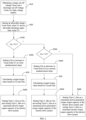
- FIG. 1 is a flowchart of a torque control method for an electric drive system according to an embodiment of the present invention. As shown in FIG. 1 , in the present embodiment, the torque control method includes actions at S10 to S60.
- a charge cut-off voltage Umax and a discharge cut-off voltage Umin of the high-voltage battery is obtained.
- the actions at S10 includes: obtaining a state parameter of the high-voltage battery, in which the state parameter including a battery SOC and/or a battery temperature, etc.; and determining the charge cut-off voltage Umax and the discharge cut-off voltage Umin of the high-voltage battery based on the state parameter.
- the charge cut-off voltage Umax also known as a charge-off end voltage, refers to a voltage at which the battery reaches a fully charged state during a specified constant current charging period. When charging continues after reaching the end voltage, overcharging is caused, which generally damages the performances and life of the battery.
- a manufacturer of the high-voltage battery will do a lot of tests on the battery to determine the charge cut-off voltage Umax of the high-voltage battery that meets the requirements of safe life.
- an allowable charge lower limit value U1 and an allowable discharge upper limit value U2 are set.
- the allowable charge lower limit value U1 is smaller than the charge cut-off voltage Umax, and the allowable discharge upper limit value U2 is greater than the discharge cut-off voltage Umin.
- a difference between the charge cut-off voltage Umax and a first set value is set as the allowable charge lower limit value U1, and the first set value is a calibrated positive number, e.g., a value ranging from 8 to 15, which may be 8, 10, 15, or the like.
- a sum of the discharge cut-off voltage Umin and a second set value is set as an allowable discharge upper limit value U2, and the second set value is a calibrated positive number, and the second set value may be the same value as the first set value, e.g., a value ranging from 8 to 15, which may be 8, 10, 15, or the like.
- an actual voltage Ua of the high-voltage battery is compared with each of the allowable charge lower limit value U1 and the allowable discharge upper limit value U2.
- a dynamic target voltage value is set when the actual voltage Ua of the high-voltage battery is greater than or equal to the allowable charge lower limit value U1 or is smaller than or equal to the allowable discharge upper limit value U2.
- the dynamic target voltage value is configured to prevent the voltage of the high-voltage battery from going beyond each of the charge cut-off voltage Umax and the discharge cut-off voltage Umin.
- a target torque value Tm is calculated based on the actual voltage Ua of the high-voltage battery and the dynamic target voltage value Udy.
- an available torque limit value of the electric drive system is set based on the target torque value Tm and a comparison result of the actual voltage Ua of the high-voltage battery with each of the allowable charge lower limit value U1 and the allowable discharge upper limit value U2. Further, a torque output of the motor is controlled based on the available torque limit value. That is, the output torque of the motor is constrained not to exceed this available torque limit value.
- the actual voltage Ua exceeds the allowable charge lower limit value U1 and is close to the charge cut-off voltage Umax, or exceeds the allowable discharge upper limit value U2 and is close to the discharge cut-off voltage Umin
- the actual voltage Ua of the high-voltage battery is controlled by setting the dynamic target voltage value. That is, on the basis of the limitations of the discharge cut-off voltage Umin and the charge cut-off voltage Umax, a reasonable buffer space is established for an allowable charge capacity or discharge capacity of the high-voltage battery.
- an available torque of the electric drive system in a power generation state or electric state at this time is constrained, and a case where the voltage of the high-voltage battery is raised to be higher than a maximum allowable operating voltage or pulled down to be lower than the minimum allowable operating voltage, without limiting its electric torque, is avoided.
- the actual voltage Ua of the high-voltage battery is close to its charge cut-off voltage Umax or discharge cut-off voltage Umin, the voltage is stabilized as much as possible to prevent the voltage from further rising beyond its charge cut-off voltage Umax or further falling below its discharge cut-off voltage Umin, thereby avoiding damages of overcharge or overload to the high-voltage battery and ensuring the service life of the battery.
- FIG. 2 is a flowchart of a torque control method for an electric drive system according to another embodiment of the present invention.
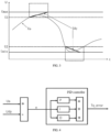
- FIG. 3 is a diagram of a correspondence of various voltage parameters in a torque control method for an electric drive system according to an embodiment of the present invention.
- an abscissa is a time
- an ordinate is a voltage value.
- the action at S30 includes actions at S302 and S304
- the action at S40 includes actions at S402 and S404.
- the dynamic target voltage value Udy is set to increase to the charge cut-off voltage Umax from the allowable charge lower limit value U1 at a first predetermined slope.
- the dynamic target voltage value Udy is set to decrease to the discharge cut-off voltage Umin from the allowable discharge upper limit value U2 at a second predetermined slope.
- the present invention can achieve a smooth transition of the actual voltage Ua of the high-voltage battery by reasonably setting the first predetermined slope and the second predetermined slope. Further, the present invention can achieve a smooth transition of an available power generation torque limit value TqAvl_Gen of the electric drive system or a smooth transition of an available electric torque limit value TqAvl_Mot of the electric drive system, thereby avoiding the problems in terms of drivability such as whole vehicle impact caused by the sudden change in the torque output of the electric drive system, that is, ensuring a smooth transition of the driving torque of the whole vehicle.
- the dynamic target voltage value Udy is set to increase to the charge cut-off voltage Umax from the allowable charge lower limit value U1 at the first predetermined slope, when the voltage of the high-voltage battery is greater than or equal to the allowable charge lower limit value Ul; and the dynamic target voltage value Udy is set to decrease to the discharge cut-off voltage Umin from the allowable discharge upper limit value U2 at the second predetermined slope, when the voltage of the high-voltage battery is smaller than or equal to the allowable discharge upper limit value U2.
- a hysteresis is added to the charge cut-off voltage Umax and the discharge cut-off voltage Umin to avoid the impact caused by the frequent switching of torque output of the electric drive system in a stateful or stateless mode due to fluctuations in the voltage of the high-voltage battery near the charge cut-off voltage Umax or the discharge cut-off voltage Umin, thereby ensuring the smoothness of the torque output.
- the action at S50 includes: calculating a difference between the actual voltage Ua and the dynamic target voltage value Udy; calculating a torque limit value Tq_error based on the difference and a PID control algorithm; and calculating a difference between the actual output torque Tq_act of the motor and the torque limit value Tq_error as the target torque value Tm.
- FIG. 4 is a control schematic diagram in the calculation of a torque limit value Tq_error in a torque control method for an electric drive system according to another embodiment of the present invention.
- the PID controller by entering the difference between the actual voltage Ua and the dynamic target voltage value Udy into a PID controller, the PID controller performs the corresponding PID algorithm to calculate the torque limit value Tq_error.
- other algorithms may be employed to calculate the torque limit value Tq_error based on the difference between the actual voltage Ua and the dynamic target voltage value Udy, as long as the calculated torque limit value Tq_error can reflect the correspondence of the difference between the actual voltage Ua and the target voltage value Udy.
- the available torque limit value includes an available electric torque limit value TqAvl_Mot and an available power generation torque limit value TqAvl_Gen.
- the action at S60 after the actions at S402 and S50 includes action at S602, and action at S60 after actions at S404 and S50 includes action at S604.
- the available power generation torque limit value TqAvl_Gen (i.e., a maximum of available power generation torque) of the electric drive system is set as the target torque value Tm, and the available electric torque limit value TqAvl_Mot of the electric drive system is set as a maximum electric torque output capacity of the electric drive system.
- the available electric torque limit value TqAvl_Mot of the electric drive system may be set as its maximum electric torque output capacity to maximize the output of the electric torque.
- the available electric torque limit value TqAvl_Mot of the electric drive system is set as the target torque value Tm, and the available power generation torque limit value TqAvl_Gen of the electric drive system is set as a maximum power generation torque output capacity of the electric drive system.
- the available power generation torque limit value TqAvl_Gen of the electric drive system may be set as its maximum power generation torque output capacity. In this case, the electric drive system can maximize the output of the power generation torque.
- the method proceeds to the action at S406 including: setting the available power generation torque limit value TqAvl_Gen of the electric drive system as the maximum power generation torque output capacity of the electric drive system, and setting the available electric torque limit value TqAvl_Mot as a maximum electric torque output capacity of the electric drive system.
- the voltage of the high-voltage battery is between the allowable discharge upper limit value U2 and the allowable charge lower limit value U1. Therefore, the high-voltage battery is in a normal operating condition, without any special settings.
- the motor and its controller in the electric drive system usually have four-quadrant operating functions, i.e., a forward electric operation, an reverse electric operation, a forward power generation, and a reverse power generation
- the corresponding outputs of electric torque and power generation torque are also distinguished in forward and reverse modes.
- the maximum power generation torque output capacities also include a forward power generation torque output capacity and a reverse power generation torque output capacity
- the maximum electric torque output capacities also include a forward electric torque output capacity and a reverse electric torque output capacity. Therefore, it is necessary to determine an operating state of the motor, and then determine the specific maximum power generation torque output capacity and maximum electric torque output capacity based on the operating state.
- the operating state of the motor may be determined based on the actual torque of the motor and the actual rotational speed of the motor, or based on a required torque of the whole vehicle for the electric drive system and the actual rotational speed of the motor.
- the process of determining the operating state of the motor based on the actual torque of the motor and the actual rotational speed of the motor is performed in the following manners: (1) determining that the motor is in a forward electric state when the actual torque of the motor is greater than or equal to zero, and the actual rotational speed of the motor is greater than or equal to zero; (2) determining that the motor is in a forward power generation state when the actual torque of the motor is smaller than zero and the actual rotational speed of the motor is greater than or equal to zero; (3) determining that the motor is in an electric reverse state when the actual torque of the motor is smaller than zero, and the actual rotational speed of the motor is smaller than zero; and (4) determining that the motor is in a reverse power generation state when the actual torque of the motor is greater than or equal to zero and the
- the present invention further provides a torque control system for an electric drive system.
- the torque control system includes a memory and a processor.
- the memory has a control program stored thereon.
- the control program is executable by the processor to implement the torque control method according to any of the above aspects.
- the processor may be a central processing unit (CPU), or a digital processing unit, etc.
- the processor transmits and receives data through a communication interface.
- the memory is configured to store a program executed by the processor.
- the memory is any medium capable of carrying or storing a desired program code in the form of instruction or data structure and being accessible by a computer, or a combination of several storage devices.
- the above computing program may be downloaded from a computer-readable storage medium to the corresponding computing/processing device or downloaded to a computer or external storage device via a network (e.g., the Internet, local area network, wide area network and/or wireless network).
- a network e.g., the Internet, local area network, wide area network and/or
Landscapes
- Engineering & Computer Science (AREA)
- Power Engineering (AREA)
- Transportation (AREA)
- Mechanical Engineering (AREA)
- Life Sciences & Earth Sciences (AREA)
- Sustainable Development (AREA)
- Sustainable Energy (AREA)
- Electric Propulsion And Braking For Vehicles (AREA)
Applications Claiming Priority (1)
| Application Number | Priority Date | Filing Date | Title |
|---|---|---|---|
| PCT/CN2021/086355 WO2022217389A1 (fr) | 2021-04-12 | 2021-04-12 | Procédé de commande de couple et système de commande de couple pour système d'entraînement électrique |
Publications (2)
| Publication Number | Publication Date |
|---|---|
| EP4324689A1 true EP4324689A1 (fr) | 2024-02-21 |
| EP4324689A4 EP4324689A4 (fr) | 2024-06-12 |
Family
ID=81510607
Family Applications (1)
| Application Number | Title | Priority Date | Filing Date |
|---|---|---|---|
| EP21936286.0A Pending EP4324689A4 (fr) | 2021-04-12 | 2021-04-12 | Procédé de commande de couple et système de commande de couple pour système d'entraînement électrique |
Country Status (3)
| Country | Link |
|---|---|
| EP (1) | EP4324689A4 (fr) |
| CN (1) | CN114502415B (fr) |
| WO (1) | WO2022217389A1 (fr) |
Families Citing this family (2)
| Publication number | Priority date | Publication date | Assignee | Title |
|---|---|---|---|---|
| CN116572756B (zh) * | 2023-05-26 | 2025-05-16 | 东风汽车集团股份有限公司 | 一种轮毂电机汽车转矩计算方法 |
| CN118358380B (zh) * | 2024-04-22 | 2025-10-31 | 奇瑞汽车股份有限公司 | 一种车辆扭矩控制方法和装置 |
Family Cites Families (22)
| Publication number | Priority date | Publication date | Assignee | Title |
|---|---|---|---|---|
| JP3700531B2 (ja) * | 2000-04-05 | 2005-09-28 | スズキ株式会社 | ハイブリッド車両の制御装置 |
| DE10301531A1 (de) * | 2003-01-17 | 2004-08-05 | Daimlerchrysler Ag | Einrichtung und Verfahren zum Betrieb einer elektrischen Maschine eines Kraftfahrzeuges |
| US6831429B2 (en) * | 2003-03-10 | 2004-12-14 | Visteon Global Technologies, Inc. | Prediction of available torque and power from battery-powered traction motor |
| JP4802945B2 (ja) * | 2006-08-31 | 2011-10-26 | トヨタ自動車株式会社 | 二次電池の制御システムおよびそれを搭載したハイブリッド車両 |
| JP4179383B2 (ja) * | 2007-02-13 | 2008-11-12 | トヨタ自動車株式会社 | 駆動力発生システムおよびそれを備える車両、ならびにその制御方法 |
| CN101284532B (zh) * | 2007-12-28 | 2012-03-28 | 奇瑞汽车股份有限公司 | 一种混合动力汽车的电池荷电状态soc的控制方法 |
| US8138720B2 (en) * | 2008-02-26 | 2012-03-20 | Afs Trinity Power Corporation | System and method for dual energy storage management |
| US7795825B2 (en) * | 2008-09-15 | 2010-09-14 | Caterpillar Inc | Over-voltage and under-voltage management for electric drive system |
| DE112009005050B4 (de) * | 2009-07-09 | 2015-05-13 | Toyota Jidosha Kabushiki Kaisha | Brennstoffzellensystem und Steuerverfahren hierfür |
| WO2011055937A2 (fr) * | 2009-11-03 | 2011-05-12 | (주)브이이엔에스 | Voiture électrique et procédé de commande de celle-ci |
| JP5454789B2 (ja) * | 2010-04-27 | 2014-03-26 | 三菱自動車工業株式会社 | 電動車両の制御装置 |
| JP2012050158A (ja) * | 2010-08-24 | 2012-03-08 | Suzuki Motor Corp | 電動車両 |
| JP5774336B2 (ja) * | 2011-03-18 | 2015-09-09 | ニチユ三菱フォークリフト株式会社 | 車両および車両の制御装置ならびに車両の制御方法 |
| CN102431465B (zh) * | 2011-11-07 | 2014-04-09 | 湖南南车时代电动汽车股份有限公司 | 一种纯电动车电池系统的保护控制方法 |
| US9156358B2 (en) * | 2013-10-15 | 2015-10-13 | Ford Global Technologies, Llc | Regenerative braking in the presence of an antilock braking system control event |
| CN104835989B (zh) * | 2014-03-27 | 2017-10-10 | 北京车和家信息技术有限责任公司 | 动力蓄电池的保护方法及装置 |
| CN104868515B (zh) * | 2014-11-18 | 2017-07-11 | 北汽福田汽车股份有限公司 | 一种获取充电电流限值和放电电流限值的方法及装置 |
| DE102016003738A1 (de) * | 2016-03-31 | 2017-10-05 | Wilo Se | Zwischenkreisspannungsabhängige Rückspeiseenergiebegrenzung für elektrische Antriebe |
| CN106451592B (zh) * | 2016-07-29 | 2019-04-05 | 北京车和家信息技术有限公司 | 电池充放电的控制方法、电池充放电的控制设备和电动车 |
| CN106585402A (zh) * | 2016-12-01 | 2017-04-26 | 安徽鸿创新能源动力有限公司 | 一种动力电池充放电控制方法 |
| JP7047603B2 (ja) * | 2018-06-01 | 2022-04-05 | トヨタ自動車株式会社 | 車両 |
| CN111959279A (zh) * | 2020-07-24 | 2020-11-20 | 苏州汇川联合动力系统有限公司 | 电机控制器母线电流控制方法、电机控制器及存储介质 |
-
2021
- 2021-04-12 CN CN202180005524.8A patent/CN114502415B/zh active Active
- 2021-04-12 EP EP21936286.0A patent/EP4324689A4/fr active Pending
- 2021-04-12 WO PCT/CN2021/086355 patent/WO2022217389A1/fr not_active Ceased
Also Published As
| Publication number | Publication date |
|---|---|
| EP4324689A4 (fr) | 2024-06-12 |
| WO2022217389A1 (fr) | 2022-10-20 |
| CN114502415B (zh) | 2024-03-12 |
| CN114502415A (zh) | 2022-05-13 |
Similar Documents
| Publication | Publication Date | Title |
|---|---|---|
| CN110861538B (zh) | 燃料电池汽车混合动力控制方法及系统 | |
| CN102161315B (zh) | 车辆用电源装置 | |
| US8305085B2 (en) | Lithium-ion battery controlling apparatus and electric vehicle | |
| US8674659B2 (en) | Charge control device and vehicle equipped with the same | |
| US9425647B2 (en) | Charging-control apparatus and charging-control method | |
| US20160141681A1 (en) | Fuel Cell System, Fuel Cell Vehicle, and Method for Controlling Fuel Cell System | |
| CN101842927B (zh) | 燃料电池的输出控制装置 | |
| WO2012137456A1 (fr) | Procédé servant à déterminer une durée de vie restante | |
| CN113085588B (zh) | 燃料电池车辆 | |
| US20180198145A1 (en) | Fuel cell system for vehicle and control method thereof | |
| JP2019512201A (ja) | 蓄電池充電のための制御装置および蓄電池を充電する方法 | |
| EP4324689A1 (fr) | Procédé de commande de couple et système de commande de couple pour système d'entraînement électrique | |
| US12304346B2 (en) | Device and method for increasing the range of an electric vehicle | |
| CN118056313A (zh) | 电池的放电方法和放电装置 | |
| CN118238620A (zh) | 一种汽车动力电池电压异常处理方法、装置和新能源汽车 | |
| US20230378799A1 (en) | Charge method and charge apparatus for battery | |
| US20240039322A1 (en) | Charging Control Method and Charging Control System | |
| JP2017162721A (ja) | セルバランス回路制御装置、及び、セルバランス回路制御方法 | |
| US12083925B2 (en) | Driving control device and driving system for vehicle | |
| CN107482274B (zh) | 燃料电池系统 | |
| JP7582241B2 (ja) | 二次電池の制御装置、および、二次電池の満充電容量推定方法 | |
| CN116278962A (zh) | 一种动力电池的管理方法、装置、电子设备及车辆 | |
| WO2023195887A1 (fr) | Dispositif de commande et procédé de commande de charge d'un dispositif de stockage d'énergie | |
| KR20220090206A (ko) | 다이오드를 이용한 배터리 이상 방지 장치 및 방법 | |
| CN114851914B (zh) | 一种动力电池的控制方法、控制装置和控制器 |
Legal Events
| Date | Code | Title | Description |
|---|---|---|---|
| STAA | Information on the status of an ep patent application or granted ep patent |
Free format text: STATUS: THE INTERNATIONAL PUBLICATION HAS BEEN MADE |
|
| PUAI | Public reference made under article 153(3) epc to a published international application that has entered the european phase |
Free format text: ORIGINAL CODE: 0009012 |
|
| STAA | Information on the status of an ep patent application or granted ep patent |
Free format text: STATUS: REQUEST FOR EXAMINATION WAS MADE |
|
| 17P | Request for examination filed |
Effective date: 20231011 |
|
| AK | Designated contracting states |
Kind code of ref document: A1 Designated state(s): AL AT BE BG CH CY CZ DE DK EE ES FI FR GB GR HR HU IE IS IT LI LT LU LV MC MK MT NL NO PL PT RO RS SE SI SK SM TR |
|
| REG | Reference to a national code |
Ref country code: DE Ref legal event code: R079 Free format text: PREVIOUS MAIN CLASS: B60L0058140000 Ipc: B60L0015200000 |
|
| A4 | Supplementary search report drawn up and despatched |
Effective date: 20240508 |
|
| RIC1 | Information provided on ipc code assigned before grant |
Ipc: H01M 10/44 20060101ALI20240503BHEP Ipc: H02J 7/00 20060101ALI20240503BHEP Ipc: B60L 58/10 20190101ALI20240503BHEP Ipc: B60L 58/15 20190101ALI20240503BHEP Ipc: B60L 58/14 20190101ALI20240503BHEP Ipc: B60L 15/20 20060101AFI20240503BHEP |
|
| DAV | Request for validation of the european patent (deleted) | ||
| DAX | Request for extension of the european patent (deleted) |