EP4324769B1 - Fördersystem - Google Patents
Fördersystem Download PDFInfo
- Publication number
- EP4324769B1 EP4324769B1 EP22190627.4A EP22190627A EP4324769B1 EP 4324769 B1 EP4324769 B1 EP 4324769B1 EP 22190627 A EP22190627 A EP 22190627A EP 4324769 B1 EP4324769 B1 EP 4324769B1
- Authority
- EP
- European Patent Office
- Prior art keywords
- conveyor belt
- conveying
- conveying section
- helical path
- conveyor
- Prior art date
- Legal status (The legal status is an assumption and is not a legal conclusion. Google has not performed a legal analysis and makes no representation as to the accuracy of the status listed.)
- Active
Links
Images



Classifications
-
- B—PERFORMING OPERATIONS; TRANSPORTING
- B65—CONVEYING; PACKING; STORING; HANDLING THIN OR FILAMENTARY MATERIAL
- B65G—TRANSPORT OR STORAGE DEVICES, e.g. CONVEYORS FOR LOADING OR TIPPING, SHOP CONVEYOR SYSTEMS OR PNEUMATIC TUBE CONVEYORS
- B65G21/00—Supporting or protective framework or housings for endless load-carriers or traction elements of belt or chain conveyors
- B65G21/16—Supporting or protective framework or housings for endless load-carriers or traction elements of belt or chain conveyors for conveyors having endless load-carriers movable in curved paths
- B65G21/18—Supporting or protective framework or housings for endless load-carriers or traction elements of belt or chain conveyors for conveyors having endless load-carriers movable in curved paths in three-dimensionally curved paths
-
- B—PERFORMING OPERATIONS; TRANSPORTING
- B65—CONVEYING; PACKING; STORING; HANDLING THIN OR FILAMENTARY MATERIAL
- B65G—TRANSPORT OR STORAGE DEVICES, e.g. CONVEYORS FOR LOADING OR TIPPING, SHOP CONVEYOR SYSTEMS OR PNEUMATIC TUBE CONVEYORS
- B65G37/00—Combinations of mechanical conveyors of the same kind, or of different kinds, of interest apart from their application in particular machines or use in particular manufacturing processes
-
- B—PERFORMING OPERATIONS; TRANSPORTING
- B65—CONVEYING; PACKING; STORING; HANDLING THIN OR FILAMENTARY MATERIAL
- B65G—TRANSPORT OR STORAGE DEVICES, e.g. CONVEYORS FOR LOADING OR TIPPING, SHOP CONVEYOR SYSTEMS OR PNEUMATIC TUBE CONVEYORS
- B65G2207/00—Indexing codes relating to constructional details, configuration and additional features of a handling device, e.g. Conveyors
- B65G2207/24—Helical or spiral conveying path
Definitions
- the present invention relates to a conveying system for transporting a product in vertical direction, comprising a drivable endless first conveyor belt and a drivable endless second conveyor belt, each having a conveying section for supporting and transporting a product and a return section, which conveying section extends along at least a helical path including a plurality of windings about a centreline between a lower end and an upper end of the helical path, wherein the lower end of the helical path of the conveying section of the first conveyor belt is located at a lower level than the lower end of the helical path of the conveying section of the second conveyor belt, wherein the upper end of the helical path of the conveying section of the second conveyor belt is located at a higher level than the upper end of the helical path of the conveying section of the first conveyor belt.
- Such a conveying system is known from EP 3 228 564 .
- the known conveying system is suitable for conveying products in vertical direction through two or more endless conveyor belts which are stacked onto each other. This provides a tall helical conveying system which has a long total helical transport path, but wherein a single extremely long conveyor belt is avoided.
- NL1040707A discloses a conveying system according to the preamble of claim 1.
- An object of the invention is to provide an improved conveying system.
- the conveying system which is characterized in that the upper end of the helical path of the conveying section of the first conveyor belt is located between the lower end and the upper end of the helical path of the conveying section of the second conveyor belt, wherein the conveying system is provided with a transfer region between the lower end of the helical path of the conveying section of the second conveyor belt and the upper end of the helical path of the conveying section of the first conveyor belt where the first and second conveyor belts extend parallel and next to each other and move in the same direction of movement under operating conditions and with a transfer member for displacing a product between the first and second conveyor belts at the transfer region.
- the conveying system provides the opportunity to transport a product successively by the first conveyor belt and the second conveyor belt between the lower end of the helical path of the conveying section of the first conveyor belt and the upper end of the helical path of the conveying section of the second conveyor belt or vice versa.
- a product can be placed on the conveyor belt at the lower end of the helical path of the first conveyor belt and transported upwardly along the helical path of the conveying section of the first conveyor belt.
- the product arrives at the transfer region where it can be transferred from the first conveyor belt to the second conveyor belt in transverse direction of the first and second conveyor belts.
- the product can be transported further upwardly along the helical path of the conveying section of the second conveyor belt in a direction towards the upper end of the helical path of the second conveyor belt. Since the first and second conveyor belts are parallel and next to each other at the transfer region the displacement between the first and second conveyor belts can be performed smoothly.
- a further advantage of the conveying system according to the invention is that the arrangement of the two conveyor belts create a tall helical conveying system having separate endless conveyor belts which have relatively limited lengths.
- the conveying section of each of the first and second conveyor belts is suitable for transporting a product in a horizontal direction or inclined direction.
- the return section may be unsuitable for transporting a product because of the orientation of the conveyor belt; for example, a product supporting side or upper side of the conveyor belt may face horizontally or downwardly at the return section.
- the first and second conveyor belts may be slat belts having slats which are movable with respect to each other and often mounted on top of an endless driving element such as a chain.
- the slats may be elongate in transverse direction of the direction of movement of the slat belt under operating conditions.
- the helical paths of the conveying sections of the first and second conveyor belts may have respective coinciding central axes.
- the return section of at least one of the first and second conveyor belts may extend below the conveying section, following the helical path of the conveying section upside down with respect to the conveying section.
- the return section of at least one of the first and second conveyor belts may extend along a non-helical path. This provides the opportunity to guide the at least one of the first and second conveyor belts along a relatively short path which is shorter than a helical path.
- the at least one of the first and second conveyor belts has a downward bend which is located such that the conveyor belt follows a horizontally oriented upper path between the upper end of the helical path of its conveying section and the downward bend and a vertically oriented path below the downward bend, which vertically oriented path is located at an outer side of the windings of the helical path of its conveying section.
- the at least one of the first and second conveyor belts has a reverse bend at the lower end of the helical path of its conveying section for turning the conveyor belt upside down, wherein the at least one of the first and second conveyor belts follows a horizontally oriented lower path between the reverse bend and an upward bend, wherein the at least one of the first and second conveyor belts follows the vertically oriented path between the downward bend and the upward bend.
- the horizontally oriented upper path may be considered as being a non-helical path of the conveying section of the at least one of the first and second conveyor belts, such that the conveying section follows a helical path as well as a non-helical path.
- the downward bend is an upper downward bend and the at least one of the first and second conveyor belts has a lower downward bend which is located between the vertically oriented path and a horizontally oriented lower path, wherein the vertically oriented path between the upper downward bend and the lower downward bend has a J-shape and the horizontally oriented lower path extends between the lower downward bend and the lower end of the helical path of its conveying section.
- the at least one of the first and second conveyor belts successively follows the horizontally oriented upper path, the downward bend, the J-shaped vertically oriented path, the lower downward bend, the horizontally oriented lower path, or vice versa.
- the at least one of the first and second conveyor belts can have only positive bends, i.e. at the upper and lower downward bends the at least one of the first and second conveyor belts bends about an axis extending perpendicularly to the direction of movement under operating conditions and below a product supporting side or an upper side thereof.
- the at least one of the first and second conveyor belts bends about an axis which extends perpendicularly to the product supporting side or the upper side thereof.
- a bottom of the J-shape will be located below the height level of a lower winding of the helical path of the conveying section of the at least one of the first and second conveyor belts.
- the J-shaped vertically oriented path may extend within a vertical plane. This means that the at least one of the first and second conveyor belts bends within a plane in which its product supporting side or its upper side lies.
- the first conveyor belt has the reverse bend at the lower end of the helical path of its conveying section and follows the horizontally oriented lower path between the reverse bend and the upward bend and the vertically oriented path between the downward bend and the upward bend of the first conveyor belt
- the second conveyor belt has the upper downward bend and the lower downward bend, which lower downward bend is located between the vertically oriented path and the horizontally oriented lower path of the second conveyor belt
- the vertically oriented path between the upper downward bend and the lower downward bend of the second conveyor belt has a J-shape and its horizontally oriented lower path extends between the lower downward bend and the lower end of the helical path of its conveying section.
- a lower part of the J-shape may be located next to the windings or a part of the windings of the helical path of the conveying section of the first conveyor belt. If the first conveyor belt would also have the J-shape there must be sufficient space below the lower winding of the conveying section of the first conveyor belt to accommodate it. If the first conveyor belt is located at a position just above the floor the J-shape may be undesired.
- the transfer region along the first and second conveyor belts may be shorter than one winding, preferably smaller than a half winding.
- the transfer member may be adapted such that it pushes a passing product from one of the first conveyor belt and the second conveyor belt to the other one of the first conveyor belt and the second conveyor belt.
- the transfer member may comprise a guide which extends along the transfer region and which is located such that under operating conditions a passing product is forced from the one of the first conveyor belt and the second conveyor belt to the other one of the first conveyor belt and the second conveyor belt.
- the transfer member may be controllable between a transfer mode in which the transfer member is adapted such that it displaces a passing product from one of the first conveyor belt and the second conveyor belt to the other one of the first conveyor belt and the second conveyor belt and a non-transfer mode in which the transfer member does not displace a passing product from one of the first conveyor belt and the second conveyor belt to the other one of the first conveyor belt and the second conveyor belt.
- a transfer mode in which the transfer member is adapted such that it displaces a passing product from one of the first conveyor belt and the second conveyor belt to the other one of the first conveyor belt and the second conveyor belt
- a non-transfer mode in which the transfer member does not displace a passing product from one of the first conveyor belt and the second conveyor belt to the other one of the first conveyor belt and the second conveyor belt.
- At least an edge portion of an upper side of the conveying section of the one of the first conveyor belt and the second conveyor belt lies at a higher level than at least an edge portion of an upper side of the conveying section of the other one of the first conveyor belt and the second conveyor belt, which edge portions are adjacent to each other and extend along te transfer region.
- the product may tilt over the edge, hence loosing contact with the one of the first conveyor belt and the second conveyor belt and contacting the other one of the first conveyor belt and the second conveyor belt.
- This minimizes the time period in which a product contacts both the first conveyor belt and the second conveyor belt.
- the product supporting side may be provided with an anti-slip coating, which should preferably be maintained.
- the upper sides of the first and second conveyor belts are angled with respect to each other such that their common upper side forms an angle larger than 180° as seen in cross-section.
- a lifting element is provided between the conveying sections of the first and second conveyor belts at the transfer region, which lifting element is adapted such that an upper side thereof gradually rises above the first and second conveyor belts in the direction of movement of the first and second conveyor belts in order to lift a product that is moving from the one of the first conveyor belt and the second conveyor belt to the other one of the first conveyor belt and the second conveyor belt before it arrives at the other one of the first conveyor belt and the second conveyor belt.
- the way of transferring a product between parallel conveyor belts as described above is not limited to the stack of the first and second conveyor belts or to helical conveyor belts, but may also be applicable in general to conveyor belts which are parallel and next to each other and driven in the same direction.
- the speeds of the first conveyor belt and the second conveyor belt are controlled such that their angular speeds are substantially the same at the transfer region. This minimizes friction and therefore wear when a product contacts the first and second conveyor belts at the same time during transferring the product between the first and second conveyor belts.
- the helical paths of the conveying sections of the first and second conveyor belts may have such radii that imaginary projections thereof on a plane perpendicular to their centrelines fit into each other. This means that the helical paths of the conveying sections of the first and second conveyor belts are different such that they fit within each other to form a nested structure.
- the second conveyor belt forms an outer track and the first conveyor belt forms an inner track at the transfer region.
- the centrelines of the helical paths of the conveying sections of the first and second conveyor belts may coincide.
- the conveying system comprises at least a drivable endless third conveyor belt having a conveying section for supporting and transporting a product and a return section, which conveying section of the third conveyor belt extends along at least a helical path including a plurality of windings about a centreline between a lower end and an upper end of the helical path of the conveying section of the third conveyor belt, wherein the upper end of the helical path of the conveying section of the third conveyor belt is located at a higher level than the upper end of the helical path of the conveying section of the second conveyor belt and wherein the upper end of the helical path of the conveying section of the second conveyor belt is located between the lower end and the upper end of the helical path of the conveying section of the third conveyor belt, wherein the transfer region is a first transfer region and the conveying system is provided with a second transfer region between the lower end of the helical path of the conveying section of the third conveyor belt and the upper end of the helical path of the
- the first conveyor belt forms an outer track and the second conveyor belt forms an inner track
- the second conveyor belt forms an inner track and the third conveyor belt forms an outer track
- the first and third conveyor belts can be driven at the same speed which is different from the speed at which the second conveyor belt is driven such that the angular speeds of the first and second conveyor belts at the first transfer region as well as the angular speeds of the second and third conveyor belts at the second transfer regions are the same.
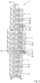
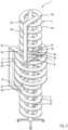
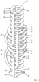
- Figs. 1 and 2 show an embodiment of a conveying system 1 according to the invention.
- the conveying system 1 is suitable for transporting a product upwardly or downwardly, i.e. in vertical direction.
- the conveying system 1 comprises a drivable endless first conveyor belt 2, a drivable endless second conveyor belt 3 and a drivable endless third conveyor belt 4.
- the first to third conveyor belts 2-4 may be well-known slat belts having slats which are movable with respect to each other and often mounted on top of an endless driving element such as a chain.
- the slat belt follows bends about an axis extending perpendicularly to its direction of movement and below a product supporting side thereof, i.e. a positive bend, than bends about an axis extending perpendicularly to the direction of movement and above the product supporting side thereof, i.e. a negative bend, since the minimum radius of the positive bend can be smaller than the minimum radius of the negative bend.
- Each of the first to third conveyor belts 2-4 has a conveying section 2a-4a for supporting and transporting a product and a return section 2b-4b.
- Each of the conveying sections 2a-4a extends along a helical path including a plurality of windings between a lower end 2c-4c and an upper end 2d-4d of the helical path.
- the helical paths have centrelines which coincide.
- the return sections 2b-4b also extend along respective helical paths below the respective conveying sections 2a-4a.
- the first to third conveyor belts 2-4 are reverted at the respective upper ends 2d-4d and lower ends 2c-4c of the helical paths of the corresponding conveying sections 2a-4a, i.e. positive bends, for example by means of reversing rollers, such that the respective return sections 2b-4b follow helical paths below the conveying sections 2a-4a.
- the lower end 2c of the helical path of the conveying section 2a of the first conveyor belt 2 is located at a lower height level than the lower end 3c of the helical path of the conveying section 3a of the second conveyor belt 3 and the lower end 3c of the helical path of the conveying section 3a of the second conveyor belt 3 is located at a lower height level than the lower end 4c of the helical path of the conveying section 4a of the third conveyor belt 4.
- the upper end 3d of the conveying section 3a of the second conveyor belt 3 is located at a higher height level than the upper end 2d of the conveying section 2a of the first conveyor belt 2 and the upper end 4d of the helical path of the conveying section 4a of the third conveyor belt 4 is located at a higher height level than the upper end 3d of the helical path of the conveying section 3a of the second conveyor belt 3.
- the upper end 2d of the helical path of the conveying section 2a of the first conveyor belt 2 is located between the lower end 3c and the upper end 3d of the helical path of the conveying section 3a of the second conveyor belt 3 and the upper end 3d of the helical path of the conveying section 3a of the second conveyor belt 3 is located between the lower end 4c and the upper end 4d of the helical path of the conveying section 4a of the third conveyor belt 4.
- the conveying system 1 is provided with a first transfer region 5 between the lower end 3c of the helical path of the conveying section 3a of the second conveyor belt 3 and the upper end 2d of the helical path of the conveying section 2a of the first conveyor belt 2.
- the conveying sections 2a, 3a of the first and second conveyor belts 2, 3 are parallel to each other.
- the first conveyor belt 2 forms an inner track and the second conveyor belt 3 forms an outer track at the first transfer region 5.
- the conveying system 1 is also provided with a first transfer member in the form of first guides 6a, 6b for displacing a product between the conveying sections 2a, 3a of the first and second conveyor belts 2, 3 at the first transfer region 5 so as to enable a product to be transported successively by the first conveyor belt 2 and the second conveyor belt 3 or in opposite direction.
- a first transfer member in the form of first guides 6a, 6b for displacing a product between the conveying sections 2a, 3a of the first and second conveyor belts 2, 3 at the first transfer region 5 so as to enable a product to be transported successively by the first conveyor belt 2 and the second conveyor belt 3 or in opposite direction.
- the first guides 6a, 6b may be parallel upright walls, of which an outer one 6a extends along outer bends of the conveying sections 2a, 3a of the first and second conveyor belts 2, 3 and crosses the conveying section 3a of the second conveyor belt 3 and of which an inner one 6b extends along inner bends of the conveying sections 2a, 3a of the first and second conveyor belts 2, 3 and crosses the conveying section 2a of the first conveyor belt 2. Since the conveying sections 2a, 3a of the first and second conveyor belts 2, 3 at the first transfer region 5 are parallel to each other products can be transferred smoothly between them.
- the conveying system 1 is provided with a second transfer region 7 between the lower end 4c of the helical path of the conveying section 4a of the third conveyor belt 4 and the upper end 3d of the helical path of the conveying section 3a of the second conveyor belt 3.
- the conveying sections 3a, 4a of the second and third conveyor belts 3, 4 are parallel to each other.
- the second conveyor belt 3 forms an outer track and the third conveyor belt 4 forms an inner track at the second transfer region 7.
- the conveying system 1 is also provided with a second transfer member in the form of second guides 8a, 8b for displacing a product between the conveying sections 3a, 4a of the second and third conveyor belts 3, 4 at the second transfer region 7 so as to enable a product to be transported successively by the second conveyor belt 3 and the third conveyor belt 4 or in opposite direction.
- a second transfer member in the form of second guides 8a, 8b for displacing a product between the conveying sections 3a, 4a of the second and third conveyor belts 3, 4 at the second transfer region 7 so as to enable a product to be transported successively by the second conveyor belt 3 and the third conveyor belt 4 or in opposite direction.
- the second guides 8a, 8b may be parallel upright walls, of which an outer one 8a extends along outer bends of the conveying sections 3a, 4a of the second and third conveyor belts 3, 4 and crosses the conveying section 3a of the second conveyor belt 3 and of which an inner one 8b extends along inner bends of the conveying sections 3a, 4a of the second and third conveyor belts 3, 4 and crosses the conveying section 4a of the third conveyor belt 4. Since the conveying sections 2a, 3a of the second and third conveyor belts 2, 3 at the second transfer region 7 are parallel to each other products can be transferred smoothly between them.
- the first and second transfer regions 5, 7 have a length of about a quarter of a winding of the corresponding helical paths, but this may be different in an alternative embodiment.
- the first to third conveyor belts 2-4 may be driven such that the respective conveying sections 2a-4a thereof turn clockwise as seen from above.
- a product that is placed on the first conveyor belt 2 at the lower end 2c of the helical path of its conveying section 2a will be transported upwardly and displaced outwardly by the inner one 6b of the first guides 6a, 6b at the first transfer region 5 from the first conveyor belt 2 to the second conveyor belt 3.
- the product will be transported further upwardly by the second conveyor belt 3.
- the product Upon passing the second transfer region 7 the product will be displaced inwardly from the second conveyor belt 3 to the third conveyor belt 4 by the outer one 8a of the second guides 8a, 8b.
- the product will be transported further upwardly by the third conveyor belt 4.
- the first to third conveyor belts 2-4 can be driven such that the respective conveying sections 2a-4a thereof turn anti-clockwise as seen from above so as to transport a product downwardly.
- the radii of the conveying sections 2a, 4a of the first and third conveyor belts 2, 4 along their helical paths are the same and smaller than the radius of the conveying section 3a of the second conveyor belt 3 along its helical path.
- the helical paths of the conveying sections 2a, 3a of the first and second conveyor belts 2, 3 have such radii that imaginary projections thereof on a plane perpendicular to their centrelines fit into each other.
- the helical paths of the conveying sections 3a, 4a of the second and third conveyor belts 3, 4 have such radii that imaginary projections thereof on a plane perpendicular to their centrelines fit into each other.
- the second conveyor belt 3 In order to minimize differences of speed of the conveying sections 2a, 3a of the first and second conveyor belts 2, 3 at the first transfer region 5 and the conveying sections 3a, 4a of the second and third conveyor belts 3, 4 at the second transfer region 7 the second conveyor belt 3 needs to be driven at a higher speed than the first and third conveyor belts 2, 4.
- the first to third conveyor belts 2-3 may be driven such that the angular speeds of the outer bend of the conveying section 2a of the first conveyor belt 2 and the inner bend of the conveying section 3a of the second conveyor belt at the first transfer region 5 are substantially equal and that the angular speeds of the inner bend of the conveying section 3a of the second conveyor belt 3 and the outer bend of the conveying section 4a of the third conveyor belt 4 at the second transfer region 7 are substantially equal.
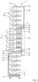
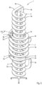
- Figs. 3 and 4 show an alternative embodiment. Parts which correspond to the embodiment as shown in Figs. 1 and 2 are referred to by the same reference numbers. It can be seen that the return sections 2b-4b of the first to third conveyor belts 2-4 follow shorter non-helical paths than in the embodiment as shown in Figs. 1 and 2 . Beyond the upper end 2d of the helical path of the conveying section 2a of the first conveyor belt 2 as seen from the helical path thereof, the conveying section 2a of the first conveyor belt 2 follows a non-helical, horizontally oriented upper path which extends below a lower winding of the helical path of the conveying section 3a of the second conveyor belt 3.
- the first conveyor belt 2 follows a downward bend 2e, i.e. a positive bend, such that the return section 2b of the first conveyor belt 2 follows a vertically oriented path outside the windings of the helical path of the conveying section 2a of the first conveyor belt 2.
- the first conveyor belt 2 follows a reverse bend 2g, i.e. a positive bend, where it is turned upside down.
- the return section 2b of the first conveyor belt 2 has a horizontally oriented lower path.
- the return section 2b of the first conveyor belt 2 has an upward bend 2f, i.e. a positive bend.
- 'horizontally oriented' and 'vertically oriented' herein means that the corresponding path may differ from exactly horizontal and vertical, respectively.
- its inclination angle is smaller than 90° or smaller than the inclination angle of a 'vertically oriented' portion of the conveyor belt having an acute inclination angle with respect to the horizontal.
- the configurations of the second and third conveyor belts 3, 4 are comparable to the configuration of the first conveyor belt 2 and are also provided with respective downward bends 3e, 4e, respective upward bends 3f, 4f, respective reverse bends 3g, 4g, respective horizontally oriented upper and lower paths and respective vertically oriented paths.
- the horizontally oriented lower path of the third conveyor belt 4 extends below un upper winding of the helical path of the conveying section of the second conveyor belt 3.
- Figs. 5 and 6 show another alternative embodiment. Parts which correspond to the embodiment as shown in Figs. 1-4 are referred to by the same reference numbers. It can be seen that the return section 2b of the first conveyor belt 2 is similar to the embodiment as shown in Figs. 3-4 .
- the second and third conveyor belts 3, 4 are provided with respective upper downward bends 3e, 4e, respective horizontally oriented upper paths between the respective upper ends 3d, 4d of the helical paths of the conveying sections 3a, 4a of the second and third conveyor belts 3, 4, respectively, and vertically oriented paths outside the windings of the helical paths of the conveying sections 2a-4a of the first to third conveyor belts 2-4.
- the vertically oriented paths of the second and third conveyor belts 3, 4 have J-shapes and extend between the upper downward bends 3e, 4e and lower downward bends 3h, 4h, respectively. Hence, the second and third conveyor belts 3, 4 do not have reverse bends where the first and second conveyor belts 3, 4 are turned upside down. Between the lower ends 3c, 4c of the helical paths of the conveying sections 3a, 4a of the second and third conveyor belts 3, 4 and the downward bends 3h, 4h of the second and third conveyor belts 3, 4 the conveying sections 3a, 4a have horizontally oriented lower paths.
- the horizontally oriented lower path of the third conveyor belt 4 extends below an upper winding of the helical path of the conveying section 3a of the second conveyor belt 3.
- Figs. 5 and 6 show that the first to third conveyor belts 2-4 are arranged such that the vertically oriented paths of the return sections 2b-4b are located at the same side of the conveying system 1, which provides a compact configuration.
- Figs. 5 and 6 show that the downward bends 3e, 4e at the horizontally oriented upper paths and the downward bends 3h, 4h at the horizontally oriented lower paths are positive bends.
- the second and third conveyor belts 2, 3 bend about respective axes which extend perpendicularly to planes in which the product supporting sides or the upper sides of the second and third conveyor belts 2, 3 lie.
- the return section 2b of the first conveyor belt 2 may also be J-shaped like the return sections 3b, 4b of the second and third conveyor belts 3, 4, respectively, but in that case there should be sufficient space at a lower height level than the lower winding of the first conveyor belt 2 to accommodate the J-shape.
- one or more of the return sections of the first to third conveyor belts have a reverse J-shape, which configuration is disclosed in EP 3 228 564 .
- the upper end and the lower end of the helical path of the corresponding conveying section may have respective reverse bends to horizontally oriented upper and lower paths of the corresponding return section, whereas upward bends may be present between the vertically oriented reverse J-shape and the upper and lower horizontally oriented paths, respectively.
- the conveyor belts would follow positive bends only.
- Fig. 7 shows an embodiment of the conveying system 1 which is similar to the embodiment as shown in Fig. 5 and 6 .
- the vertically oriented paths of the return sections 3b, 4b of the second and third conveyor belts 3, 4 have J-shapes, but in this case the length of the path that each of the second and third conveyor belts 3, 4 follows along the J-shape between the upper downward bend 3e, 4e and the lower downward bend 3h, 4h is variable. Due to this feature the total length of the second and third conveyor belts 3, 4 may vary.
- the conveyor belt 3, 4 at the bottom of the J-shape may be guided by a U-shaped frame which is movable with respect to the upper and lower downward bends 3h, 4h, 3e, 4e, which have fixed locations. It is also possible that the second and third conveyor belts 3, 4 freely suspend from the upper and lower downward bends 3h, 4h, 3e, 4e or from fixed locations below the upper and lower downward bends 3h, 4h, 3e, 4e, i.e. without support of a frame. The lengths of the second and third conveyor belts 3, 4 may be compensated automatically due to their own weight at the bottom of the J-shape or by means of an actuator or a spring or the like.
- the conveying system can be defined as follows.
- a conveying system for transporting a product in vertical direction comprising a drivable endless conveyor belt 3 for supporting and transporting a product, which conveyor belt 3 extends along a helical path including a plurality of windings between a lower end 3c and an upper end 3d thereof, wherein the conveyor belt 3 follows a non-helical path between the upper end 3d and the lower end 3c outside the helical path, wherein the conveyor belt 3 has an upper downward bend 3e which is located such that the conveyor belt 3 follows a horizontally oriented upper path between the upper end 3d and the upper downward bend 3e and a lower downward bend 3h which is located such that the conveyor belt 3 follows a horizontally oriented lower path between the lower end 3c and the lower downward bend 3h and wherein the conveyor belt 3 has a vertically oriented section extending downwardly from both the upper and lower downward bends 3e, 3h and following a J-shaped path between the upper and lower downward bends 3e, 3h.
- a conveying system according to aspect 1, wherein the vertically oriented section extends within a vertical plane.
- Aspect 3 A conveying system according to aspect 1 or 2, wherein the length of the path that the conveyor belt 3 follows along the J-shape between the upper downward bend 3e and the lower downward bend 3h is variable.
- a conveying system according to aspect 3, wherein a portion of the conveyor belt 3 freely suspends from the upper and lower downward bends 3e, 3h or from locations below the upper and lower downward bends 3e, 3h within upwardly directed legs of the J-shape such that the weight of the freely suspending portion of the conveyor belt 3 automatically lowers a bottom of the J-shape in case of increasing length of the conveyor belt 3.
- Fig. 8 shows in detail how a product P which is transported upwardly by the second conveyor belt 3 is transferred from the conveying section 3a of the second conveyor belt 3 to the conveying section 4a of the third conveyor belt 4.
- the product P is forced by the outer one 8a of the second guides 8a, 8b.
- the upper sides of the conveying sections 3a, 4a of the first and second conveyor belts 2, 3 are flush with each other. This means that the product P slides over both the second and third conveyor belts 3, 4.
- Fig. 9 shows an alternative embodiment in which in cross-section of the second transfer region 7 the upper sides of the conveying sections 3a, 4a of the second and third conveyor belts 3, 4 are horizontal, but wherein the upper sides of the conveying section 3a of the second conveyor belt 3 lies slightly higher than the upper side of the conveying section 4a of the third conveyor belt 4. Consequently, the product P which passes the second transfer region 7 will be supported by the second conveyor belt 3 and move above the third conveyor belt 4 without contacting the third conveyor belt 4.
- the product P may tilt about the inner bend of the second conveyor belt 3 and contact the third conveyor belt 4 when its centre of gravity passes the inner bend of the second conveyor belt 3. This means that the period in which the product P is supported by both the second and third conveyor belts 3, 4 is relatively short.
- At least an edge portion 3a' of the upper side of the conveying section 3a of the second conveyor belt 3 lies at a higher level than at least an edge portion 4a' of the upper side of the conveying section 4a of the third conveyor belt 4, which edge portions 3a', 4a' are adjacent to each other and extend along the second transfer region 7.
- Fig. 10 shows an embodiment which is comparable to the embodiment as shown in Fig. 9 , but wherein the second conveyor belt 3 is banked or inclined.
- the upper sides of the first and second conveyor belts 2, 3 are angled with respect to each other such that there common upper side forms an angle larger than 180° as seen in cross-section.
- Figs. 11A and 11B show an embodiment wherein the transfer of a product P is illustrated at two different locations along the second transfer region 7.
- Fig. 11A shows a situation in which the outer one 8a of the second guides 8a, 8b has just started to push the product P towards the third conveyor belt 4.
- a lifting element in the form of an upwardly directed plate 10 which has an upper rim that gradually raises along the second transfer region 7 in the direction of movement of the first and second conveyor belts 3, 4.
- the upper rim is flush with the upper sides of the second and third conveyor belts 3, 4 or just below thereof.
- 11B shows a situation further downstream where the upper rim of the plate 10 projects above the upper sides of the second and third conveyor belts 3, 4.
- the passing product P is tilted by the plate 10 and at the same time forced to move towards the third conveyor belt 4.
- the product P will tilt to the third conveyor belt 4 and supported and transported by the third conveyor belt 4 only.
- Figs. 8-11 may also be applied to conveyor belts which are parallel and next to each other and driven in the same direction, without being limited to the stack of the conveyor belts or to helical conveyor belts as described hereinbefore.
Landscapes
- Engineering & Computer Science (AREA)
- Mechanical Engineering (AREA)
- Structure Of Belt Conveyors (AREA)
Claims (15)
- Fördersystem (1) zum Transportieren eines Produkts in vertikaler Richtung, aufweisend ein antreibbares endloses erstes Förderband (2) und ein antreibbares endloses zweites Förderband (3), die jeweils einen Förderabschnitt (2a, 3a) zum Tragen und Transportieren eines Produkts und einen Rückführabschnitt (2b, 3b) aufweisen, welcher Förderabschnitt (2a, 3a) sich entlang wenigstens einer wendelförmigen Bahn erstreckt, die eine Mehrzahl von Windungen um eine Mittellinie herum zwischen einem unteren Ende (2c, 3c) und einem oberen Ende (2d, 3d) der wendelförmigen Bahn aufweist, wobei das untere Ende (2c) der wendelförmigen Bahn des Förderabschnitts (2a) des ersten Förderbandes (2) auf einem niedrigeren Niveau als das untere Ende (3c) der wendelförmigen Bahn des Förderabschnitts (3a) des zweiten Förderbandes (3) angeordnet ist, wobei das obere Ende (3d) der wendelförmigen Bahn des Förderabschnitts (3a) des zweiten Förderbands (3) auf einem höheren Niveau als das obere Ende (2d) der wendelförmigen Bahn des Förderabschnitts (2a) des ersten Förderbands (2) angeordnet ist, wobei das obere Ende (2d) der wendelförmigen Bahn des Förderabschnitts (2a) des ersten Förderbands (2) zwischen dem unteren Ende (3c) und dem oberen Ende (3d) der wendelförmigen Bahn des Förderabschnitts (3a) des zweiten Förderbands (3) angeordnet ist, wobei das Fördersystem (1) mit einem Übergabebereich (5) zwischen dem unteren Ende (3c) der wendelförmigen Bahn des Förderabschnitts (3a) des zweiten Förderbands (3) und dem oberen Ende (2d) der wendelförmigen Bahn des Förderabschnitts (2a) des ersten Förderbands (2) versehen ist, wo sich das erste und das zweite Förderband (2, 3) parallel nebeneinander erstrecken,
dadurch gekennzeichnet, dass sich das erste und das zweite Förderband (2, 3) unter Betriebsbedingungen in der gleichen Bewegungsrichtung bewegen und wobei im Übertragungsbereich (5) ein Übertragungselement (5) zum Verlagern eines Produkts zwischen dem ersten und dem zweiten Förderband (2, 3) vorliegt. - Fördersystem (1) gemäß Anspruch 1, wobei der Rückführabschnitt (2b, 3b) von wenigstens einem von dem ersten und dem zweiten Förderband (2, 3) sich unterhalb des Förderabschnitts (2a, 3a) erstreckt, wobei er der wendelförmigen Bahn des Förderabschnitts (2a, 3a) in Bezug auf den Förderabschnitt (2a, 3a) auf dem Kopf stehend folgt.
- Fördersystem (1) gemäß Anspruch 1, wobei der Rückführabschnitt (2b, 3b) von wenigstens einem von dem ersten und dem zweiten Förderband (2, 3) entlang einer nichtwendelförmigen Bahn verläuft.
- Fördersystem (1) gemäß Anspruch 3, wobei das wenigstens eine von dem ersten und dem zweiten Förderband (2, 3) eine Abwärtsbiegung (2e, 3e) aufweist, die so angeordnet ist, dass das Förderband (2, 3) einer horizontal ausgerichteten oberen Bahn zwischen dem oberen Ende (2d, 3d) der wendelförmigen Bahn seines Förderabschnitts (2a, 3a) und der Abwärtsbiegung (2e, 3e) und einer vertikal ausgerichteten Bahn unterhalb der Abwärtsbiegung (2e, 3e) folgt, wobei die vertikal ausgerichtete Bahn an einer Außenseite der Windungen der wendelförmigen Bahn seines Förderabschnitts (2a, 3a) angeordnet ist.
- Fördersystem (1) gemäß Anspruch 4, wobei das wenigstens eine von dem ersten und dem zweiten Förderband (2, 3) eine Umdrehbiegung (2g, 3g) am unteren Ende (2c, 3c) der wendelförmigen Bahn seines Förderabschnitts (2a, 3a) aufweist, um das Förderband (2, 3) auf den Kopf zu stellen, wobei das wenigstens eine von dem ersten und dem zweiten Förderband (2, 3) einer horizontal ausgerichteten unteren Bahn zwischen der Umdrehbiegung (2g, 3g) und einer Aufwärtsbiegung (2f, 3f) folgt, wobei das wenigstens eine von dem ersten und dem zweiten Förderband (2, 3) der vertikal ausgerichteten Bahn zwischen der Abwärtsbiegung (2e, 3e) und der Aufwärtsbiegung (2f, 3f) folgt.
- Fördersystem (1) gemäß Anspruch 4, wobei die Abwärtsbiegung eine obere Abwärtsbiegung (3e) ist und das wenigstens eine von dem ersten und dem zweiten Förderband (3) eine untere Abwärtsbiegung (3h) aufweist, die zwischen der vertikal ausgerichteten Bahn und einer horizontal ausgerichteten unteren Bahn angeordnet ist, wobei die vertikal ausgerichtete Bahn zwischen der oberen Abwärtsbiegung (3e) und der unteren Abwärtsbiegung (3h) eine J-Form hat und die horizontal ausgerichtete untere Bahn sich zwischen der unteren Abwärtsbiegung (3h) und dem unteren Ende (3c) der wendelförmigen Bahn seines Förderabschnitts (3a) erstreckt.
- Fördersystem (1) gemäß Anspruch 6, wobei die J-förmige vertikal ausgerichtete Bahn sich innerhalb einer vertikalen Ebene erstreckt.
- Fördersystem (1), wobei das erste Förderband (2) in Anspruch 5 definiert ist und das zweite Förderband (3) in Anspruch 6 oder 7 definiert ist.
- Fördersystem (1) gemäß irgendeinem der vorhergehenden Ansprüche, wobei der Übergabebereich (5) entlang des ersten und des zweiten Förderbands (2, 3) kürzer als eine Windung ist, vorzugsweise kleiner als eine halbe Windung.
- Fördersystem (1) gemäß irgendeinem der vorhergehenden Ansprüche, wobei das Übertragungselement (5) so angepasst ist, dass es ein vorbeipassierendes Produkt von einem von dem ersten Förderband (2) und dem zweiten Förderband (3) auf das andere von dem ersten Förderband (2) und dem zweiten Förderband (3) schiebt.
- Fördersystem (1) gemäß Anspruch 10,wobei im Übergabebereich (5) Oberseiten der Förderabschnitte (2a, 3a) des ersten und des zweiten Förderbands (2, 3) miteinander bündig sind, oderwobei wenigstens ein Randabschnitt einer Oberseite des Förderabschnitts (2a) des einen von dem ersten Förderband (2) und dem zweiten Förderband (3) auf einem höheren Niveau liegt als wenigstens ein Randabschnitt einer Oberseite des Förderabschnitts (3a) des anderen von dem ersten Förderband (2) und dem zweiten Förderband (3), welche Randabschnitte zueinander benachbart sind und sich entlang des Übergabebereichs (5) erstrecken, oderwobei die Oberseiten des ersten und des zweiten Förderbandes (2, 3) bezüglich einander so abgewinkelt sind, dass ihre gemeinsame Oberseite im Querschnitt gesehen einen Winkel von größer als 180° bildet, oderwobei ein Hebeelement zwischen den Förderabschnitten (2a, 3a) des ersten und des zweiten Förderbandes (2, 3) im Übergabebereich (5) vorgesehen ist, welches Hebeelement so angepasst ist, dass sich eine Oberseite davon allmählich über das erste und das zweite Förderband (2, 3) in der Bewegungsrichtung des ersten und des zweiten Förderbands (2, 3) erhebt, um ein Produkt anzuheben, das sich von dem einen von dem ersten Förderband (2) und dem zweiten Förderband (3) zu dem anderen von dem ersten Förderband (2) und dem zweiten Förderbands (3) bewegt, bevor es das andere von dem ersten Förderband (2) und dem zweiten Förderband (3) erreicht.
- Fördersystem (1) gemäß irgendeinem der vorhergehenden Ansprüche, wobei unter Betriebsbedingungen die Geschwindigkeiten des ersten Förderbandes (2) und des zweiten Förderbandes (3) so gesteuert werden, dass ihre Winkelgeschwindigkeiten im Übergabebereich (5) im Wesentlichen gleich sind.
- Fördersystem (1) gemäß irgendeinem der vorhergehenden Ansprüche, wobei die wendelförmigen Bahnen der Förderabschnitte (2a, 3a) des ersten und des zweiten Förderbandes (2, 3) solche Radien haben, dass imaginäre Projektionen davon auf eine Ebene senkrecht zu ihren Mittellinien ineinanderpassen.
- Fördersystem (1) gemäß Anspruch 12, wobei die Mittellinien der wendelförmigen Bahnen der Förderabschnitte (2a, 3a) des ersten und des zweiten Förderbandes (2, 3) zusammenfallen.
- Fördersystem (1) gemäß irgendeinem der vorhergehenden Ansprüche, wobei das Fördersystem (1) wenigstens ein antreibbares endloses drittes Förderband (4) aufweist, das einen Förderabschnitt (4a) zum Tragen und Transportieren eines Produkts und einen Rückführabschnitt (4b) aufweist, welcher Förderabschnitt (4a) des dritten Förderbandes (4) sich entlang wenigstens einer wendelförmigen Bahn erstreckt, die eine Mehrzahl von Windungen um eine Mittellinie herum zwischen einem unteren Ende (4c) und einem oberen Ende (4d) der wendelförmigen Bahn des Förderabschnitts (4a) des dritten Förderbandes (4) aufweist, wobei das obere Ende (4d) der wendelförmigen Bahn des Förderabschnitts (4a) des dritten Förderbands (4) auf einem höheren Niveau als das obere Ende (3d) der wendelförmigen Bahn des Förderabschnitts (3a) des zweiten Förderbands (3) angeordnet ist und wobei das obere Ende (3d) der wendelförmigen Bahn des Förderabschnitts (3a) des zweiten Förderbands (3) zwischen dem unteren Ende (4c) und dem oberen Ende (4d) der wendelförmigen Bahn des Förderabschnitts (4a) des dritten Förderbands (4) angeordnet ist, wobei der Übergabebereich ein erster Übergabebereich (5) ist und das Fördersystem (1) mit einem zweiten Übergabebereich (7) zwischen dem unteren Ende (4c) der wendelförmigen Bahn des Förderabschnitts (4a) des dritten Förderbandes (4) und dem oberen Ende (3d) der wendelförmigen Bahn des Förderabschnitts (3a) des zweiten Förderbandes (3) versehen ist, wo die Förderabschnitte (3a , 4a) des zweiten und des dritten Förderbandes (3, 4) sich parallel nebeneinander erstrecken, wobei das Übertragungselement ein erstes Übertragungselement (6) ist und das Fördersystem (1) im zweiten Übertragungsbereich (7) mit einem zweiten Übertragungselement (8) zum Verlagern eines Produkts zwischen dem zweiten und dem dritten Förderband (3, 4) versehen ist.
Priority Applications (2)
| Application Number | Priority Date | Filing Date | Title |
|---|---|---|---|
| EP22190627.4A EP4324769B1 (de) | 2022-08-16 | 2022-08-16 | Fördersystem |
| US18/449,441 US12448217B2 (en) | 2022-08-16 | 2023-08-14 | Conveying system |
Applications Claiming Priority (1)
| Application Number | Priority Date | Filing Date | Title |
|---|---|---|---|
| EP22190627.4A EP4324769B1 (de) | 2022-08-16 | 2022-08-16 | Fördersystem |
Publications (3)
| Publication Number | Publication Date |
|---|---|
| EP4324769A1 EP4324769A1 (de) | 2024-02-21 |
| EP4324769C0 EP4324769C0 (de) | 2025-05-28 |
| EP4324769B1 true EP4324769B1 (de) | 2025-05-28 |
Family
ID=82940060
Family Applications (1)
| Application Number | Title | Priority Date | Filing Date |
|---|---|---|---|
| EP22190627.4A Active EP4324769B1 (de) | 2022-08-16 | 2022-08-16 | Fördersystem |
Country Status (2)
| Country | Link |
|---|---|
| US (1) | US12448217B2 (de) |
| EP (1) | EP4324769B1 (de) |
Family Cites Families (4)
| Publication number | Priority date | Publication date | Assignee | Title |
|---|---|---|---|---|
| NL1040707B1 (nl) * | 2014-03-06 | 2015-11-19 | Willem Takens Jan | Buffertransporteur voor het transporteren en bufferen van losse en staafvormige producten. |
| DE102016102474A1 (de) * | 2016-02-12 | 2017-08-17 | Hauni Maschinenbau Gmbh | Vorrichtung zum Fördern eines Massenstroms stabförmiger Artikel und Verwendung derselben |
| ES2963007T3 (es) | 2016-04-08 | 2024-03-22 | Ambaflex Int B V | Un transportador y un sistema de transporte |
| IT201700115173A1 (it) * | 2017-10-12 | 2019-04-12 | Gd Spa | Magazzino a capacità variabile |
-
2022
- 2022-08-16 EP EP22190627.4A patent/EP4324769B1/de active Active
-
2023
- 2023-08-14 US US18/449,441 patent/US12448217B2/en active Active
Also Published As
| Publication number | Publication date |
|---|---|
| EP4324769A1 (de) | 2024-02-21 |
| EP4324769C0 (de) | 2025-05-28 |
| US20240083685A1 (en) | 2024-03-14 |
| US12448217B2 (en) | 2025-10-21 |
Similar Documents
| Publication | Publication Date | Title |
|---|---|---|
| US5350050A (en) | Continuous vertical conveyor | |
| CN110772781B (zh) | 麻将机及其拾牌搬运系统 | |
| US7963389B2 (en) | Conveyor | |
| US8770376B2 (en) | Buffer conveyor for conveying and buffering products | |
| EP2644538B1 (de) | Förderer | |
| US5070999A (en) | Helical conveyor/accumulator | |
| US4346803A (en) | Conveyor | |
| JPH0229567B2 (de) | ||
| US12269692B2 (en) | Accumulating conveyor | |
| EP2039626A1 (de) | Vorrichtung für den Transport von Produkten | |
| KR0141351B1 (ko) | 트레이의 운반 방법 및 장치 | |
| KR900001282B1 (ko) | 불안정한 용기의 로딩을 위하여 특히 유용한 로딩장치 | |
| US20110180373A1 (en) | Buffer conveyor for conveying and buffering products | |
| EP4324769A1 (de) | Fördersystem | |
| EP3825261B1 (de) | Förderer und fördersystem | |
| GB2061216A (en) | Device for temporary storage of material on trays, pallets or the like | |
| JPH101214A (ja) | 製品搬送方法及び装置 | |
| CN120229539B (zh) | 一种货物升降码包自动转运设备 | |
| KR102111220B1 (ko) | 음료용기 하역장치 | |
| JPH074688Y2 (ja) | 自動販売機の商品搬送装置 | |
| JPH0761571A (ja) | 物品の連続搬送装置 | |
| GB2233625A (en) | Mechanical handling device | |
| JPH10226408A (ja) | 垂直搬送装置 |
Legal Events
| Date | Code | Title | Description |
|---|---|---|---|
| PUAI | Public reference made under article 153(3) epc to a published international application that has entered the european phase |
Free format text: ORIGINAL CODE: 0009012 |
|
| STAA | Information on the status of an ep patent application or granted ep patent |
Free format text: STATUS: THE APPLICATION HAS BEEN PUBLISHED |
|
| AK | Designated contracting states |
Kind code of ref document: A1 Designated state(s): AL AT BE BG CH CY CZ DE DK EE ES FI FR GB GR HR HU IE IS IT LI LT LU LV MC MK MT NL NO PL PT RO RS SE SI SK SM TR |
|
| STAA | Information on the status of an ep patent application or granted ep patent |
Free format text: STATUS: REQUEST FOR EXAMINATION WAS MADE |
|
| 17P | Request for examination filed |
Effective date: 20240731 |
|
| RBV | Designated contracting states (corrected) |
Designated state(s): AL AT BE BG CH CY CZ DE DK EE ES FI FR GB GR HR HU IE IS IT LI LT LU LV MC MK MT NL NO PL PT RO RS SE SI SK SM TR |
|
| GRAP | Despatch of communication of intention to grant a patent |
Free format text: ORIGINAL CODE: EPIDOSNIGR1 |
|
| RIC1 | Information provided on ipc code assigned before grant |
Ipc: B65G 21/18 20060101AFI20241127BHEP |
|
| STAA | Information on the status of an ep patent application or granted ep patent |
Free format text: STATUS: GRANT OF PATENT IS INTENDED |
|
| INTG | Intention to grant announced |
Effective date: 20250102 |
|
| GRAS | Grant fee paid |
Free format text: ORIGINAL CODE: EPIDOSNIGR3 |
|
| GRAA | (expected) grant |
Free format text: ORIGINAL CODE: 0009210 |
|
| STAA | Information on the status of an ep patent application or granted ep patent |
Free format text: STATUS: THE PATENT HAS BEEN GRANTED |
|
| AK | Designated contracting states |
Kind code of ref document: B1 Designated state(s): AL AT BE BG CH CY CZ DE DK EE ES FI FR GB GR HR HU IE IS IT LI LT LU LV MC MK MT NL NO PL PT RO RS SE SI SK SM TR |
|
| REG | Reference to a national code |
Ref country code: GB Ref legal event code: FG4D |
|
| REG | Reference to a national code |
Ref country code: CH Ref legal event code: EP |
|
| REG | Reference to a national code |
Ref country code: IE Ref legal event code: FG4D Ref country code: DE Ref legal event code: R096 Ref document number: 602022015155 Country of ref document: DE |
|
| U01 | Request for unitary effect filed |
Effective date: 20250618 |
|
| U07 | Unitary effect registered |
Designated state(s): AT BE BG DE DK EE FI FR IT LT LU LV MT NL PT RO SE SI Effective date: 20250627 |
|
| U20 | Renewal fee for the european patent with unitary effect paid |
Year of fee payment: 4 Effective date: 20250827 |
|
| PG25 | Lapsed in a contracting state [announced via postgrant information from national office to epo] |
Ref country code: ES Free format text: LAPSE BECAUSE OF FAILURE TO SUBMIT A TRANSLATION OF THE DESCRIPTION OR TO PAY THE FEE WITHIN THE PRESCRIBED TIME-LIMIT Effective date: 20250528 |
|
| PG25 | Lapsed in a contracting state [announced via postgrant information from national office to epo] |
Ref country code: GR Free format text: LAPSE BECAUSE OF FAILURE TO SUBMIT A TRANSLATION OF THE DESCRIPTION OR TO PAY THE FEE WITHIN THE PRESCRIBED TIME-LIMIT Effective date: 20250829 Ref country code: NO Free format text: LAPSE BECAUSE OF FAILURE TO SUBMIT A TRANSLATION OF THE DESCRIPTION OR TO PAY THE FEE WITHIN THE PRESCRIBED TIME-LIMIT Effective date: 20250828 |
|
| PG25 | Lapsed in a contracting state [announced via postgrant information from national office to epo] |
Ref country code: PL Free format text: LAPSE BECAUSE OF FAILURE TO SUBMIT A TRANSLATION OF THE DESCRIPTION OR TO PAY THE FEE WITHIN THE PRESCRIBED TIME-LIMIT Effective date: 20250528 |
|
| PG25 | Lapsed in a contracting state [announced via postgrant information from national office to epo] |
Ref country code: HR Free format text: LAPSE BECAUSE OF FAILURE TO SUBMIT A TRANSLATION OF THE DESCRIPTION OR TO PAY THE FEE WITHIN THE PRESCRIBED TIME-LIMIT Effective date: 20250528 |
|
| PG25 | Lapsed in a contracting state [announced via postgrant information from national office to epo] |
Ref country code: RS Free format text: LAPSE BECAUSE OF FAILURE TO SUBMIT A TRANSLATION OF THE DESCRIPTION OR TO PAY THE FEE WITHIN THE PRESCRIBED TIME-LIMIT Effective date: 20250828 |
|
| PG25 | Lapsed in a contracting state [announced via postgrant information from national office to epo] |
Ref country code: IS Free format text: LAPSE BECAUSE OF FAILURE TO SUBMIT A TRANSLATION OF THE DESCRIPTION OR TO PAY THE FEE WITHIN THE PRESCRIBED TIME-LIMIT Effective date: 20250928 |
|
| PG25 | Lapsed in a contracting state [announced via postgrant information from national office to epo] |
Ref country code: SM Free format text: LAPSE BECAUSE OF FAILURE TO SUBMIT A TRANSLATION OF THE DESCRIPTION OR TO PAY THE FEE WITHIN THE PRESCRIBED TIME-LIMIT Effective date: 20250528 |
|
| PG25 | Lapsed in a contracting state [announced via postgrant information from national office to epo] |
Ref country code: CZ Free format text: LAPSE BECAUSE OF FAILURE TO SUBMIT A TRANSLATION OF THE DESCRIPTION OR TO PAY THE FEE WITHIN THE PRESCRIBED TIME-LIMIT Effective date: 20250528 |
|
| PG25 | Lapsed in a contracting state [announced via postgrant information from national office to epo] |
Ref country code: SK Free format text: LAPSE BECAUSE OF FAILURE TO SUBMIT A TRANSLATION OF THE DESCRIPTION OR TO PAY THE FEE WITHIN THE PRESCRIBED TIME-LIMIT Effective date: 20250528 |
|
| REG | Reference to a national code |
Ref country code: CH Ref legal event code: H13 Free format text: ST27 STATUS EVENT CODE: U-0-0-H10-H13 (AS PROVIDED BY THE NATIONAL OFFICE) Effective date: 20260324 |
|
| PG25 | Lapsed in a contracting state [announced via postgrant information from national office to epo] |
Ref country code: MC Free format text: LAPSE BECAUSE OF FAILURE TO SUBMIT A TRANSLATION OF THE DESCRIPTION OR TO PAY THE FEE WITHIN THE PRESCRIBED TIME-LIMIT Effective date: 20250528 |
|
| PLBE | No opposition filed within time limit |
Free format text: ORIGINAL CODE: 0009261 |
|
| STAA | Information on the status of an ep patent application or granted ep patent |
Free format text: STATUS: NO OPPOSITION FILED WITHIN TIME LIMIT |
|
| REG | Reference to a national code |
Ref country code: CH Ref legal event code: L10 Free format text: ST27 STATUS EVENT CODE: U-0-0-L10-L00 (AS PROVIDED BY THE NATIONAL OFFICE) Effective date: 20260409 |
|
| PG25 | Lapsed in a contracting state [announced via postgrant information from national office to epo] |
Ref country code: CH Free format text: LAPSE BECAUSE OF NON-PAYMENT OF DUE FEES Effective date: 20250831 |
|
| 26N | No opposition filed |
Effective date: 20260303 |