EP4324780B1 - Dispositifs de sécurité d'ascenseur - Google Patents
Dispositifs de sécurité d'ascenseur Download PDFInfo
- Publication number
- EP4324780B1 EP4324780B1 EP22190417.0A EP22190417A EP4324780B1 EP 4324780 B1 EP4324780 B1 EP 4324780B1 EP 22190417 A EP22190417 A EP 22190417A EP 4324780 B1 EP4324780 B1 EP 4324780B1
- Authority
- EP
- European Patent Office
- Prior art keywords
- landing door
- elevator
- elevator system
- memory
- safety device
- Prior art date
- Legal status (The legal status is an assumption and is not a legal conclusion. Google has not performed a legal analysis and makes no representation as to the accuracy of the status listed.)
- Active
Links
Images

Classifications
-
- H—ELECTRICITY
- H02—GENERATION; CONVERSION OR DISTRIBUTION OF ELECTRIC POWER
- H02J—ELECTRIC POWER NETWORKS; CIRCUIT ARRANGEMENTS OR SYSTEMS FOR SUPPLYING OR DISTRIBUTING ELECTRIC POWER; SYSTEMS FOR STORING ELECTRIC ENERGY
- H02J9/00—Circuit arrangements for emergency or stand-by power supply, e.g. for emergency lighting
- H02J9/04—Circuit arrangements for emergency or stand-by power supply, e.g. for emergency lighting in which the distribution system is disconnected from the normal source and connected to a standby source
- H02J9/06—Circuit arrangements for emergency or stand-by power supply, e.g. for emergency lighting in which the distribution system is disconnected from the normal source and connected to a standby source with automatic change-over, e.g. UPS systems
-
- B—PERFORMING OPERATIONS; TRANSPORTING
- B66—HOISTING; LIFTING; HAULING
- B66B—ELEVATORS; ESCALATORS OR MOVING WALKWAYS
- B66B5/00—Applications of checking, fault-correcting, or safety devices in elevators
- B66B5/0006—Monitoring devices or performance analysers
- B66B5/0018—Devices monitoring the operating condition of the elevator system
-
- B—PERFORMING OPERATIONS; TRANSPORTING
- B66—HOISTING; LIFTING; HAULING
- B66B—ELEVATORS; ESCALATORS OR MOVING WALKWAYS
- B66B13/00—Doors, gates, or other apparatus controlling access to, or exit from, cages or lift well landings
- B66B13/02—Door or gate operation
- B66B13/14—Control systems or devices
-
- B—PERFORMING OPERATIONS; TRANSPORTING
- B66—HOISTING; LIFTING; HAULING
- B66B—ELEVATORS; ESCALATORS OR MOVING WALKWAYS
- B66B13/00—Doors, gates, or other apparatus controlling access to, or exit from, cages or lift well landings
- B66B13/22—Operation of door or gate contacts
-
- B—PERFORMING OPERATIONS; TRANSPORTING
- B66—HOISTING; LIFTING; HAULING
- B66B—ELEVATORS; ESCALATORS OR MOVING WALKWAYS
- B66B5/00—Applications of checking, fault-correcting, or safety devices in elevators
- B66B5/0006—Monitoring devices or performance analysers
- B66B5/0018—Devices monitoring the operating condition of the elevator system
- B66B5/0031—Devices monitoring the operating condition of the elevator system for safety reasons
-
- B—PERFORMING OPERATIONS; TRANSPORTING
- B66—HOISTING; LIFTING; HAULING
- B66B—ELEVATORS; ESCALATORS OR MOVING WALKWAYS
- B66B5/00—Applications of checking, fault-correcting, or safety devices in elevators
- B66B5/0043—Devices enhancing safety during maintenance
- B66B5/005—Safety of maintenance personnel
-
- B—PERFORMING OPERATIONS; TRANSPORTING
- B66—HOISTING; LIFTING; HAULING
- B66B—ELEVATORS; ESCALATORS OR MOVING WALKWAYS
- B66B5/00—Applications of checking, fault-correcting, or safety devices in elevators
- B66B5/02—Applications of checking, fault-correcting, or safety devices in elevators responsive to abnormal operating conditions
-
- H—ELECTRICITY
- H02—GENERATION; CONVERSION OR DISTRIBUTION OF ELECTRIC POWER
- H02J—ELECTRIC POWER NETWORKS; CIRCUIT ARRANGEMENTS OR SYSTEMS FOR SUPPLYING OR DISTRIBUTING ELECTRIC POWER; SYSTEMS FOR STORING ELECTRIC ENERGY
- H02J7/00—Circuit arrangements for charging or discharging batteries or for supplying loads from batteries
- H02J7/40—Circuit arrangements for charging or discharging batteries or for supplying loads from batteries characterised by the exchange of charge or discharge related data
-
- H—ELECTRICITY
- H02—GENERATION; CONVERSION OR DISTRIBUTION OF ELECTRIC POWER
- H02J—ELECTRIC POWER NETWORKS; CIRCUIT ARRANGEMENTS OR SYSTEMS FOR SUPPLYING OR DISTRIBUTING ELECTRIC POWER; SYSTEMS FOR STORING ELECTRIC ENERGY
- H02J7/00—Circuit arrangements for charging or discharging batteries or for supplying loads from batteries
- H02J7/865—Battery or charger load switching, e.g. concurrent charging and load supply
-
- H—ELECTRICITY
- H02—GENERATION; CONVERSION OR DISTRIBUTION OF ELECTRIC POWER
- H02M—APPARATUS FOR CONVERSION BETWEEN AC AND AC, BETWEEN AC AND DC, OR BETWEEN DC AND DC, AND FOR USE WITH MAINS OR SIMILAR POWER SUPPLY SYSTEMS; CONVERSION OF DC OR AC INPUT POWER INTO SURGE OUTPUT POWER; CONTROL OR REGULATION THEREOF
- H02M7/00—Conversion of AC power input into DC power output; Conversion of DC power input into AC power output
- H02M7/02—Conversion of AC power input into DC power output without possibility of reversal
- H02M7/04—Conversion of AC power input into DC power output without possibility of reversal by static converters
-
- H—ELECTRICITY
- H02—GENERATION; CONVERSION OR DISTRIBUTION OF ELECTRIC POWER
- H02M—APPARATUS FOR CONVERSION BETWEEN AC AND AC, BETWEEN AC AND DC, OR BETWEEN DC AND DC, AND FOR USE WITH MAINS OR SIMILAR POWER SUPPLY SYSTEMS; CONVERSION OF DC OR AC INPUT POWER INTO SURGE OUTPUT POWER; CONTROL OR REGULATION THEREOF
- H02M7/00—Conversion of AC power input into DC power output; Conversion of DC power input into AC power output
- H02M7/42—Conversion of DC power input into AC power output without possibility of reversal
- H02M7/44—Conversion of DC power input into AC power output without possibility of reversal by static converters
Definitions
- the present invention relates to elevator safety devices.
- Elevator systems typically feature one or more elevator cars running in a hoistway to carry passengers or goods between floors of a building.
- Landing doors (sometimes also referred to as hoistway doors) on each landing provide access to the elevator car.
- the landing doors also provide access to the hoistway itself, e.g. for maintenance purposes. For instance, the lowest landing door might be used for accessing a pit area at the bottom of the hoistway.
- elevator systems continually monitor the landing doors to detect if they are open or closed (e.g. with landing door switches).
- the elevator system may take appropriate safety action if a landing door is detected as being open at an unexpected time. For instance, if a lowest landing door is detected as being open without an adjacent elevator car, the system may presume that the pit area is being accessed by a technician and force the elevator car to operate in an inspection mode. This may limit the speed of operation of the car and/or limit movement into particular zones in the hoistway to ensure that the technician can work safely in the pit area. The technician, on leaving the pit area, then manually resets the safety system to allow a normal operational mode to resume.
- US 2018/0215579 A1 discloses a monitoring unit and sensor that detects changes in state in an elevator shaft door using a sequence of pulses monitoring signal.
- the monitoring unit has a battery and can be switched to an autonomous mode when the elevator system is entirely or partially disabled.
- the monitoring unit in the autonomous mode, records state data from the sensor and is connected to a safeguard unit that reads and evaluates the recorded state data, and prevents the elevator system from being put into the normal mode of operation if a change in the state of one of the monitored doors has been detected.
- EP3348508 A1 discloses an arrangement for detecting state information of an automatic door comprising a magnetometer, at least one permanent magnet, and a control unit.
- the control unit may comprise a battery in order to provide power to the control unit.
- the control unit may comprise a memory.
- an elevator system according to claim 1.
- the elevator safety device can provide improved monitoring of the landing door, because the landing door sensor can be powered with the power source when the power supply of the elevator system is unavailable.
- This allows, for instance, the state of the landing door to be monitored during an interruption to the elevator system's power supply, and for information about said state to be read from the memory once the interruption is over. For example, if the memory indicates that the landing door was not opened during an interruption to the elevator system's power supply, the elevator system can deduce that no-one has accessed the hoistway during the interruption and that full operational mode can be resumed immediately, without requiring manual intervention.
- the elevator safety device may be simple to retrofit to existing elevator systems, because it can utilise an existing landing door sensor.
- the elevator safety device may simply be connected to the landing door sensor in parallel with an existing landing door sensing circuit.
- the elevator safety device may be arranged to power the landing door sensor using the power source when the power supply of the elevator system is interrupted, e.g. during a power cut or during planned downtime. This may ensure that the landing door continues to be monitored even when the power supply of the elevator system is unavailable.
- the elevator safety device may be arranged to begin to power the landing door sensor using the power source in response to an interruption to the power supply of the elevator system (e.g. in response to a signal indicating the interruption of the power supply).
- the elevator safety device may be arranged to monitor the power supply of the elevator system.
- the elevator safety device may be arranged to automatically power the landing door sensor using the power source when an interruption to the power supply of the elevator system is detected.
- the elevator safety device may be arranged to disconnect the landing door sensor from the power source when the power supply of the elevator system is active (e.g. when the power supply is reactivated after an interruption). Disconnecting the power source from the landing door sensor when the elevator system power supply is active may reduce redundant use of energy from the power source and may mitigate interference with an existing landing door sensing circuit.
- the elevator safety device comprises a switching arrangement (e.g. a relay) that is arranged to controllably connect the power source to the landing door sensor.
- the power supply may be the main power supply of the elevator system, e.g. that is used to power the movement of one or more elevator cars in the hoistway between landings.
- the power source may be arranged to power only the landing door sensor and the elevator safety device itself. This may allow the use of a relatively low cost and low size power source.
- the power source comprises a battery, a capacitor or a supercapacitor.
- the power source may have an energy capacity of less than 5 Wh, less than 1 Wh or less than 0.5 Wh.
- the elevator safety device may be arranged to recharge the power source using the power supply of the elevator system.
- the elevator safety device may be arranged to communicate with an elevator controller of the elevator system, e.g. to report the recorded state of the landing door to an elevator controller.
- the elevator safety device may be arranged to report the state of the landing door recorded by the memory to the elevator controller following (e.g. immediately following) an interruption to the power supply of the elevator system.
- the elevator controller is arranged to control the elevator system according to the state of the landing door recorded by the memory. For instance, the elevator controller may be arranged to perform a safety action (e.g. to initiate an inspection mode) if the memory indicates that landing door has been opened. The elevator controller may be arranged to initiate a normal operational mode if the memory indicates that the landing door has not been opened.
- a safety action e.g. to initiate an inspection mode
- the elevator controller may be arranged to initiate a normal operational mode if the memory indicates that the landing door has not been opened.
- the elevator safety device comprises a microcontroller.
- the microcontroller may be arranged to communicate with an elevator controller of the elevator system.
- the microcontroller may be arranged to read from the memory and/or to reset the memory.
- the microcontroller may be arranged to act as an interface between the memory and an elevator controller.
- the microcontroller may be arranged to control the connection of the power source to the landing door sensor.
- the microcontroller may be arranged to control the switching arrangement.
- one or more of these functions may be performed directly by an elevator controller.
- the memory may be arranged to be directly readable and/or resettable by an elevator controller.
- it may be beneficial to use a microcontroller as part of the elevator safety device e.g. located physically remotely from the elevator controller) to simplify installation.
- the memory can be very small.
- the memory may comprise 32 bits of data storage or less, e.g. 16 bits or 8 bits.
- the memory is arranged to record a single data point, e.g. a single data point that indicates if the landing door has opened at any point since the memory was last reset.
- the memory may even consist of a 1-bit data storage element (i.e. a latch) arranged to change state if the landing door sensor detects an open landing door.
- a small memory may have a low cost and be simple to implement, whilst still recording sufficient information to allow the elevator system to determine if the landing door has been open at any point during a power interruption.
- the memory is arranged to record additional information, for instance to record a log of changes in the state of the landing door (e.g. a time-stamped log of landing door events).
- the memory may comprise any computer memory suitable for recording a state of the landing door.
- the memory comprises a non-volatile memory, e.g. EEPROM or flash memory.
- the memory may comprise a data buffer such as a first-in-first-out (FIFO) memory.
- the memory may comprise a hardware register.
- the elevator safety device e.g. a microcontroller of the elevator safety device
- the elevator safety device may be arranged to erase or reset the memory.
- the elevator safety device may be arranged to erase or reset the memory when starting to power the landing door sensor with the power source (e.g. when the power supply of the elevator system is interrupted).
- the elevator safety device may be arranged such that the memory is erasable or resettable directly by the elevator controller.
- the landing door sensor may comprise any landing door sensor known in the art per se.
- the landing door sensor comprises a switch which completes an electrical connection between a first electrical terminal and a second electrical terminal when the landing door is closed, and which breaks said electrical connection when the door is open (or vice versa).
- the landing door sensor may comprise a contact switch (e.g. a pair of electrical contacts coupled to respective parts of the landing door and arranged to be brought into/out of electrical contact with the opening/closing of the door).
- the landing door sensor may comprise a non-contact switch such as a reed switch.
- the power source may be arranged to be connected in series with the landing door sensor.
- the power source may be arranged to be connected in series with the switch (e.g. connected to a first terminal of the switch).
- the elevator safety device may be arranged to supply an electrical current to the switch (e.g. by connecting the switch to the power source).
- the elevator safety device may be arranged to supply direct current (DC) or alternating current (AC) to the switch.
- DC direct current
- AC alternating current
- the elevator safety device may be arranged to apply a fixed (for DC) or changing (for AC) voltage to the first terminal of the switch and to monitor a voltage on the second terminal of the switch.
- the elevator safety device may comprise a power converter (e.g. comprising a voltage regulator, a rectifier, an inverter or a switched-mode power supply) arranged to generate the fixed or changing voltage from the power source.
- the elevator safety device may comprise a sensing circuit portion arranged to sense a voltage on the second terminal of the switch.
- the presence or absence of the fixed or changing voltage at the second terminal may indicate the state of the switch and, accordingly, the state of the landing door.
- the elevator safety device can thus deduce the state of the landing door (and record this to the memory) simply by monitoring the second terminal.
- the voltage at the second terminal may be monitored and analysed to determine the state of the landing door and/or additional information about the elevator safety device or the landing door sensor. For instance, patterns in the resulting AC voltages at the second terminal may be analysed to detect not only the state of the switch but also to detect faults or issues with the switch or associated circuitry such as connecting cables.
- the memory may be arranged to be connected in series with the landing door sensor.
- the memory may be arranged to be connected in series with the switch (e.g. connected to a second terminal of the switch).
- the elevator safety device may be arranged to supply a DC voltage to the first terminal of the switch, such that the DC voltage on the second terminal is indicative of the state of the landing door.
- the DC voltage on the second terminal may be used as a direct data input to the memory to allow the memory to record the state of the landing door (e.g. a sensing circuit portion may not be required).
- the landing door sensor may comprise a dedicated landing door sensor (i.e. a landing door sensor used primarily or exclusively by the elevator safety device).
- the landing door sensor may comprise part of the elevator safety device.
- the landing door sensor comprises an existing landing door sensor of the elevator system, i.e. the elevator safety device is arranged to connect to an existing landing door sensor.
- the elevator controller is arranged to receive information from the landing door sensor independently of the elevator safety device.
- the elevator system may comprise a landing door sensing circuit arranged to connect the landing door sensor to the elevator controller independently of the elevator safety device.
- the landing door sensing circuit may be connected to the landing door sensor in parallel with the elevator safety device.
- the elevator controller is arranged to control the elevator system according to information received from the landing door sensor (e.g. a state of the landing door detected by the landing door sensor) independently of the elevator safety device. For instance, the elevator controller may be arranged to perform a safety action (e.g. initiating inspection mode) if information received from the landing door sensor independently of the elevator safety device indicates that the landing door is open at an unexpected time.
- the elevator system may be arranged to power the landing door sensor using the power supply of the elevator system.
- Elevator systems typically include several landing doors (e.g. for accessing several floors in a building). Accordingly, the elevator system may comprise a plurality of landing doors. The elevator system may comprise a corresponding plurality of landing door sensors, with each landing door sensor arranged to detect a state of a respective landing door.
- the elevator safety device may be arranged to monitor a single landing door.
- the elevator safety device may comprise a single physical device located in close proximity to the landing door it monitors (e.g. less than 5 m away or less than 2 m away).
- a plurality of elevator safety devices may be provided for a respective plurality of landing doors in an elevator system.
- the elevator system may comprise a plurality of elevator safety devices as disclosed herein, with the power source of each elevator safety device arranged to power a respective landing door sensor independently of a power supply of the elevator system and the memory of each elevator safety device arranged to record a state of the landing door detected by the respective landing door sensor when the landing door sensor is powered by the power source.
- Providing an elevator safety device for a plurality of landing doors in an elevator system (e.g. for every landing door in an elevator system) allows information on the states of all of the landing doors to be gathered during an interruption to the power supply of the elevator system.
- the elevator safety device may be arranged to monitor a plurality of landing doors.
- the power source may be arranged to power a plurality of landing door sensors independently of a power supply of the elevator system, wherein each landing door sensor is arranged to detect a state of a respective landing door.
- the memory may be arranged to record states of some or all of the plurality of landing doors detected by the landing door sensors when the landing door sensors are powered by the power source.
- the elevator safety device comprises a plurality of memories arranged to record respective states of a plurality of landing doors.
- the elevator system may comprise a first elevator safety device arranged to monitor a first set of landing doors and a second elevator safety device arranged to monitor a second set of landing doors.
- the first and second sets may be of different sizes and may each contain one or more landing doors.
- the first elevator safety device may be arranged to monitor only a lowest landing door (e.g. used for accessing a pit area) and the second elevator safety device may be arranged to monitor some or all of the other landing doors.
- the elevator safety device may comprise a single physical device, e.g. with power and/or data terminals for connecting the elevator safety device to the landing door sensor and/or the elevator system.
- the elevator safety device may be integrated with other elevator circuity, e.g. other door or pit safety devices.
- components making up the elevator safety device may be included on a single circuit board with components for other functions.
- the elevator safety device may be small enough to be installed with inside existing landing door sensor circuitry.
- the elevator safety device (or a larger device such as a circuit board which includes components making up the elevator safety device) may have a maximum dimension of less than 0.5 m, less than 0.1 m or less than 0.05 m.
- the elevator safety device may have an area footprint of less than 0.25 m 2 , less than 0.01 m 2 or less than 0.0025 m 2 .
- the elevator safety device may take up a volume of less than 0.125 m 3 , less than 0.001 m 3 or less than 0.000125 m 3 .
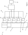
- an elevator system 2 comprises an elevator car 4 that travels in a hoistway 6 to transport passengers and/or cargo between landings 8 in a building.
- the hoistway 6 comprises a pit area 7 below the lowest landing 8.
- Each landing 8 features a landing door 10, which allows access to the elevator car 4 when it is adjacent the landing 8, and to the hoistway 6 itself when the elevator car 4 is not adjacent the landing 8.
- the elevator system 2 comprises an elevator safety system 12, comprising a plurality of landing door switches 14, a plurality of elevator safety devices 16 and an elevator controller 18. Each landing door switch 14 detects whether a corresponding landing door 10 is open or closed.
- the elevator controller 18 is connected to the landing door switches 14 via a landing door sensing circuit 15.
- the elevator system 2 is powered by a power supply 19.
- Figure 2 shows part of the elevator safety system 12 in more detail.
- Figure 2 shows one of the landing door switches 14, an elevator safety device 16 and the elevator controller 18.
- the landing door switch 14 completes an electrical connection between a first electrical terminal 28 and a second electrical terminal 30 when the landing door 10 is closed, and breaks said electrical connection when the landing door 10 is open.
- the elevator safety device 16 comprises a battery 20, a non-volatile memory 22 and a microcontroller 24.
- the battery 20 is connected to the first terminal 28 of the landing door switch 14 via a switch 26.
- the non-volatile memory 22 is connected to the second terminal 30 of the landing door switch 14.
- the microcontroller 24 is powered by the battery 20 and is in communication with the elevator controller 18.
- the elevator car 4 moves between the landings 8 carrying passengers and/or cargo. It may occasionally be necessary to access the hoistway 6. For instance, an elevator technician may wish to access the pit area 7 of the hoistway 6 to perform a maintenance operation. To do so, the technician opens the lowest landing door 10 whilst the elevator car 4 is elsewhere and climbs into the pit area 7.
- the elevator controller 18 detects that the lowest landing door 10 is open based on a signal from the lowest landing door switch 14 (via the landing door sensing circuit 15). The elevator car 4 is not adjacent that landing door 10, so the elevator controller 18 activates an inspection mode which limits the speed of operation of the elevator car 4 and prevents the elevator car 4 from moving into the pit area 7. This ensures that the technician can perform the maintenance operation in the pit area 7 safely. When the technician leaves the pit area 7, they manually indicate to the elevator controller 18 that they have left the hoistway 6, and normal operation is resumed.
- the elevator controller 18 can no longer actively monitor the state of the landing doors 10 via the landing door sensing circuit 15. Therefore, the microcontroller 24 monitors the power supply 19 (e.g. via the elevator controller 18) and when the microcontroller 24 detects an interruption in the power supply 19 it resets the memory 22 and closes the switch 26, connecting the battery 20 to the landing door switch 14. A small direct current flows through the landing door switch 14.
- the direct current through the switch 14 is interrupted.
- the non-volatile memory 22 may record a single data point that the door has been opened since the memory 22 was last reset.
- the microcontroller 24 When power to the elevator system 2 is restored, the microcontroller 24 reads the contents of the non-volatile memory 22 and sends it to the elevator controller 18. This happens for all of the elevator safety devices 16. The elevator controller 18 is thus informed if any of the landing doors 10 were opened whilst the power supply 19 was interrupted. If the contents of the memories 22 indicate that any of the landing doors 10 were opened during the interruption of the power supply 19, the elevator controller 18 restarts operation of the elevator system 2 in the inspection mode. However, if the memories 22 indicate that none of the landing doors 10 were opened during the interruption, the elevator controller 18 activates full operation mode immediately without needing any manual input.
Landscapes
- Engineering & Computer Science (AREA)
- Power Engineering (AREA)
- Automation & Control Theory (AREA)
- Business, Economics & Management (AREA)
- Emergency Management (AREA)
- Maintenance And Inspection Apparatuses For Elevators (AREA)
Claims (12)
- Système d'ascenseur (2) comprenant :une porte palière (10) ;un capteur de porte palière (14) agencé pour détecter un état de la porte palière (10) ;une alimentation électrique (19) agencée pour alimenter ledit système d'ascenseur (2) ;un dispositif de commande d'ascenseur (18) agencé pour commander le système d'ascenseur (2) ; etun dispositif de sécurité d'ascenseur (16) agencé pour surveiller ladite porte palière (10) et comprenant :une source d'alimentation (20) agencée pour alimenter le capteur de porte palière (14) indépendamment de l'alimentation électrique (19) du système d'ascenseur (2) ; etune mémoire (22) agencée pour enregistrer un état de la porte palière (10) détecté par le capteur de porte palière (14) lorsque le capteur de porte palière (14) est alimenté par la source d'alimentation (20) ;dans lequel le dispositif de commande d'ascenseur (18) est agencé pour commander le système d'ascenseur (2) en fonction de l'état de la porte palière (10) enregistré par la mémoire (22) ;et caractérisé en ce que le dispositif de commande d'ascenseur (18) est agencé pour recevoir des informations en provenance du capteur de porte palière (14) indépendamment du dispositif de sécurité d'ascenseur (16), et pour commander le système d'ascenseur (2) en fonction des informations reçues en provenance du capteur de porte palière (14) indépendamment du dispositif de sécurité d'ascenseur (16).
- Système d'ascenseur (2) selon la revendication 1, dans lequel le dispositif de sécurité d'ascenseur (16) est agencé pour alimenter le capteur de porte palière (14) à l'aide de la source d'alimentation (20) lorsque l'alimentation électrique (19) du système d'ascenseur (2) est interrompue et pour déconnecter le capteur de porte palière (14) de la source d'alimentation (20) lorsque l'alimentation électrique (19) du système d'ascenseur (2) est active.
- Système d'ascenseur (2) selon une quelconque revendication précédente, dans lequel la source d'alimentation (20) comprend une batterie, un condensateur ou un supercondensateur.
- Système d'ascenseur (2) selon une quelconque revendication précédente, dans lequel le dispositif de sécurité d'ascenseur (16) est agencé pour signaler l'état enregistré de la porte palière (10) au dispositif de commande d'ascenseur (18) du système d'ascenseur (2) suite à une interruption de l'alimentation électrique (19) du système d'ascenseur (2).
- Système d'ascenseur (2) selon une quelconque revendication 4, dans lequel le dispositif de sécurité d'ascenseur (16) comprend un microcontrôleur (24) agencé pour agir comme une interface entre la mémoire (22) et le dispositif de commande d'ascenseur (18).
- Système d'ascenseur (2) selon une quelconque revendication précédente, dans lequel la mémoire (22) est conçue pour enregistrer un seul point de données qui indique si la porte palière (10) s'est ouverte à un moment quelconque depuis la dernière réinitialisation de la mémoire (22).
- Système d'ascenseur (2) selon une quelconque revendication précédente, dans lequel la mémoire (22) comprend une mémoire non volatile.
- Système d'ascenseur (2) selon une quelconque revendication précédente, dans lequel la source d'alimentation (20) est agencée pour être connectée en série au capteur de porte palière (14).
- Système d'ascenseur (2) selon une quelconque revendication précédente, dans lequel la mémoire (22) est agencée pour être connectée en série au capteur de porte palière (14).
- Système d'ascenseur (2) selon une quelconque revendication précédente, dans lequel le dispositif de commande d'ascenseur (18) est agencé pour initier un mode d'inspection si la mémoire (22) indique que la porte palière (10) a été ouverte et pour initier un mode de fonctionnement normal si la mémoire (22) indique que la porte palière (10) n'a pas été ouverte.
- Système d'ascenseur (2) selon une quelconque revendication précédente, dans lequel :le capteur de porte palière (14) comprend un interrupteur (14) qui établit une connexion électrique entre une première borne électrique (28) et une seconde borne électrique (30) lorsque la porte palière (10) est fermée, et qui interrompt ladite connexion électrique lorsque la porte palière (10) est ouverte ; etla source d'alimentation (20) est agencée pour être connectée à la première borne (28) de l'interrupteur (14) ; etla mémoire (22) est agencée pour être connectée à la seconde borne de l'interrupteur (16).
- Système d'ascenseur (2) selon une quelconque revendication précédente, comprenant :une pluralité de portes palières (10) ;une pluralité de capteurs de portes palières (14), chaque capteur de porte palière (14) étant agencé pour détecter un état d'une porte palière respective (10) ; etun premier dispositif de sécurité d'ascenseur (16) agencé pour surveiller un premier ensemble de portes palières (10) et un second dispositif de sécurité d'ascenseur (16) agencé pour surveiller un second ensemble de portes palières (10).
Priority Applications (3)
| Application Number | Priority Date | Filing Date | Title |
|---|---|---|---|
| EP22190417.0A EP4324780B1 (fr) | 2022-08-15 | 2022-08-15 | Dispositifs de sécurité d'ascenseur |
| US17/984,787 US20240051791A1 (en) | 2022-08-15 | 2022-11-10 | Elevator safety devices |
| CN202211454147.9A CN117585550A (zh) | 2022-08-15 | 2022-11-21 | 电梯安全装置 |
Applications Claiming Priority (1)
| Application Number | Priority Date | Filing Date | Title |
|---|---|---|---|
| EP22190417.0A EP4324780B1 (fr) | 2022-08-15 | 2022-08-15 | Dispositifs de sécurité d'ascenseur |
Publications (2)
| Publication Number | Publication Date |
|---|---|
| EP4324780A1 EP4324780A1 (fr) | 2024-02-21 |
| EP4324780B1 true EP4324780B1 (fr) | 2025-05-21 |
Family
ID=82939812
Family Applications (1)
| Application Number | Title | Priority Date | Filing Date |
|---|---|---|---|
| EP22190417.0A Active EP4324780B1 (fr) | 2022-08-15 | 2022-08-15 | Dispositifs de sécurité d'ascenseur |
Country Status (3)
| Country | Link |
|---|---|
| US (1) | US20240051791A1 (fr) |
| EP (1) | EP4324780B1 (fr) |
| CN (1) | CN117585550A (fr) |
Families Citing this family (2)
| Publication number | Priority date | Publication date | Assignee | Title |
|---|---|---|---|---|
| EP4126733A1 (fr) * | 2020-03-31 | 2023-02-08 | Inventio Ag | Dispositif de surveillance de sécurité, et procédé de surveillance de sécurité d'un système d'ascenseur |
| CN121317484A (zh) * | 2024-07-11 | 2026-01-13 | 奥的斯电梯公司 | 用于检测多个层门开关的状态的方法和装置 |
Family Cites Families (6)
| Publication number | Priority date | Publication date | Assignee | Title |
|---|---|---|---|---|
| EP2243738A1 (fr) * | 2009-04-24 | 2010-10-27 | Inventio AG | Procédé destiné à la communication à l'aide d'une installation d'ascenseur |
| WO2013045271A1 (fr) * | 2011-09-29 | 2013-04-04 | Inventio Ag | Dispositif et procédé permettant de surveiller des portes palières |
| EP2976281A4 (fr) * | 2013-03-22 | 2016-11-23 | Otis Elevator Co | Maintenance préventive par détection de la durée de vie de composants |
| US10926974B2 (en) * | 2015-09-30 | 2021-02-23 | Inventio Ag | Method and apparatus for controlling an elevator system |
| EP3290375B1 (fr) * | 2016-08-29 | 2019-06-26 | KONE Corporation | Élévateur |
| ES2738424T3 (es) * | 2017-01-17 | 2020-01-22 | Kone Corp | Disposición y procedimiento para detectar al menos un parámetro operativo de una puerta automática |
-
2022
- 2022-08-15 EP EP22190417.0A patent/EP4324780B1/fr active Active
- 2022-11-10 US US17/984,787 patent/US20240051791A1/en active Pending
- 2022-11-21 CN CN202211454147.9A patent/CN117585550A/zh active Pending
Also Published As
| Publication number | Publication date |
|---|---|
| EP4324780A1 (fr) | 2024-02-21 |
| US20240051791A1 (en) | 2024-02-15 |
| CN117585550A (zh) | 2024-02-23 |
Similar Documents
| Publication | Publication Date | Title |
|---|---|---|
| US20240051791A1 (en) | Elevator safety devices | |
| CN101353125B (zh) | 电梯的安全监视系统 | |
| CN108137268B (zh) | 用于控制电梯设备的方法和装置 | |
| EP2772462B1 (fr) | Dispositif de sécurité d'ascenseur | |
| JP5516727B2 (ja) | 電子安全エレベータ | |
| CN107777500A (zh) | 电梯系统及电梯停电时供电方法 | |
| CN104854013B (zh) | 用于人员运送设备的监控装置 | |
| US11979095B2 (en) | Discharge control circuit and power conversion device | |
| CN108349692B (zh) | 用于电梯设备的监控单元和方法 | |
| EP3929129A1 (fr) | Ascenseur et procédé de commande d'ascenseur | |
| CN109132798B (zh) | 电梯装置 | |
| WO2015151256A1 (fr) | Dispositif de commande d'ascenseur | |
| JPWO2018087803A1 (ja) | エレベーター制御装置、制御方法及びエレベーター | |
| US5276292A (en) | Operation check device of dynamic brake circuit for elevator | |
| JP2019218149A (ja) | エレベータシステム | |
| BRPI0611738A2 (pt) | arranjo que tem um dispositivo de gravação | |
| EP3153445B1 (fr) | Unité de connexion de capteur, système de sécurité et ascenseur | |
| US20220169480A1 (en) | Elevator system | |
| JP7828853B2 (ja) | エレベーターシステム | |
| JP2018008760A (ja) | エレベーター | |
| JP7136155B2 (ja) | エレベータの給電異常監視装置 | |
| KR102930880B1 (ko) | 엘리베이터 카 위치추적 시스템 | |
| EP3379712B1 (fr) | Dispositif de conversion de puissance | |
| HK1244476B (zh) | 传感器连接单元、安全系统及电梯 | |
| JPS63267682A (ja) | エレベ−タの非常用電源装置 |
Legal Events
| Date | Code | Title | Description |
|---|---|---|---|
| PUAI | Public reference made under article 153(3) epc to a published international application that has entered the european phase |
Free format text: ORIGINAL CODE: 0009012 |
|
| STAA | Information on the status of an ep patent application or granted ep patent |
Free format text: STATUS: THE APPLICATION HAS BEEN PUBLISHED |
|
| AK | Designated contracting states |
Kind code of ref document: A1 Designated state(s): AL AT BE BG CH CY CZ DE DK EE ES FI FR GB GR HR HU IE IS IT LI LT LU LV MC MK MT NL NO PL PT RO RS SE SI SK SM TR |
|
| STAA | Information on the status of an ep patent application or granted ep patent |
Free format text: STATUS: REQUEST FOR EXAMINATION WAS MADE |
|
| 17P | Request for examination filed |
Effective date: 20240807 |
|
| RBV | Designated contracting states (corrected) |
Designated state(s): AL AT BE BG CH CY CZ DE DK EE ES FI FR GB GR HR HU IE IS IT LI LT LU LV MC MK MT NL NO PL PT RO RS SE SI SK SM TR |
|
| GRAP | Despatch of communication of intention to grant a patent |
Free format text: ORIGINAL CODE: EPIDOSNIGR1 |
|
| STAA | Information on the status of an ep patent application or granted ep patent |
Free format text: STATUS: GRANT OF PATENT IS INTENDED |
|
| RIC1 | Information provided on ipc code assigned before grant |
Ipc: B66B 13/22 20060101AFI20241128BHEP |
|
| INTG | Intention to grant announced |
Effective date: 20241220 |
|
| GRAS | Grant fee paid |
Free format text: ORIGINAL CODE: EPIDOSNIGR3 |
|
| GRAA | (expected) grant |
Free format text: ORIGINAL CODE: 0009210 |
|
| STAA | Information on the status of an ep patent application or granted ep patent |
Free format text: STATUS: THE PATENT HAS BEEN GRANTED |
|
| AK | Designated contracting states |
Kind code of ref document: B1 Designated state(s): AL AT BE BG CH CY CZ DE DK EE ES FI FR GB GR HR HU IE IS IT LI LT LU LV MC MK MT NL NO PL PT RO RS SE SI SK SM TR |
|
| REG | Reference to a national code |
Ref country code: GB Ref legal event code: FG4D |
|
| REG | Reference to a national code |
Ref country code: CH Ref legal event code: EP |
|
| REG | Reference to a national code |
Ref country code: DE Ref legal event code: R096 Ref document number: 602022014873 Country of ref document: DE |
|
| REG | Reference to a national code |
Ref country code: IE Ref legal event code: FG4D |
|
| REG | Reference to a national code |
Ref country code: NL Ref legal event code: MP Effective date: 20250521 |
|
| PG25 | Lapsed in a contracting state [announced via postgrant information from national office to epo] |
Ref country code: PT Free format text: LAPSE BECAUSE OF FAILURE TO SUBMIT A TRANSLATION OF THE DESCRIPTION OR TO PAY THE FEE WITHIN THE PRESCRIBED TIME-LIMIT Effective date: 20250922 Ref country code: ES Free format text: LAPSE BECAUSE OF FAILURE TO SUBMIT A TRANSLATION OF THE DESCRIPTION OR TO PAY THE FEE WITHIN THE PRESCRIBED TIME-LIMIT Effective date: 20250521 Ref country code: FI Free format text: LAPSE BECAUSE OF FAILURE TO SUBMIT A TRANSLATION OF THE DESCRIPTION OR TO PAY THE FEE WITHIN THE PRESCRIBED TIME-LIMIT Effective date: 20250521 |
|
| PGFP | Annual fee paid to national office [announced via postgrant information from national office to epo] |
Ref country code: DE Payment date: 20250724 Year of fee payment: 4 |
|
| REG | Reference to a national code |
Ref country code: LT Ref legal event code: MG9D |
|
| PG25 | Lapsed in a contracting state [announced via postgrant information from national office to epo] |
Ref country code: GR Free format text: LAPSE BECAUSE OF FAILURE TO SUBMIT A TRANSLATION OF THE DESCRIPTION OR TO PAY THE FEE WITHIN THE PRESCRIBED TIME-LIMIT Effective date: 20250822 Ref country code: NO Free format text: LAPSE BECAUSE OF FAILURE TO SUBMIT A TRANSLATION OF THE DESCRIPTION OR TO PAY THE FEE WITHIN THE PRESCRIBED TIME-LIMIT Effective date: 20250821 |
|
| PG25 | Lapsed in a contracting state [announced via postgrant information from national office to epo] |
Ref country code: NL Free format text: LAPSE BECAUSE OF FAILURE TO SUBMIT A TRANSLATION OF THE DESCRIPTION OR TO PAY THE FEE WITHIN THE PRESCRIBED TIME-LIMIT Effective date: 20250521 Ref country code: PL Free format text: LAPSE BECAUSE OF FAILURE TO SUBMIT A TRANSLATION OF THE DESCRIPTION OR TO PAY THE FEE WITHIN THE PRESCRIBED TIME-LIMIT Effective date: 20250521 |
|
| PG25 | Lapsed in a contracting state [announced via postgrant information from national office to epo] |
Ref country code: BG Free format text: LAPSE BECAUSE OF FAILURE TO SUBMIT A TRANSLATION OF THE DESCRIPTION OR TO PAY THE FEE WITHIN THE PRESCRIBED TIME-LIMIT Effective date: 20250521 |
|
| PG25 | Lapsed in a contracting state [announced via postgrant information from national office to epo] |
Ref country code: HR Free format text: LAPSE BECAUSE OF FAILURE TO SUBMIT A TRANSLATION OF THE DESCRIPTION OR TO PAY THE FEE WITHIN THE PRESCRIBED TIME-LIMIT Effective date: 20250521 |
|
| PGFP | Annual fee paid to national office [announced via postgrant information from national office to epo] |
Ref country code: FR Payment date: 20250725 Year of fee payment: 4 |
|
| PG25 | Lapsed in a contracting state [announced via postgrant information from national office to epo] |
Ref country code: RS Free format text: LAPSE BECAUSE OF FAILURE TO SUBMIT A TRANSLATION OF THE DESCRIPTION OR TO PAY THE FEE WITHIN THE PRESCRIBED TIME-LIMIT Effective date: 20250821 |
|
| PG25 | Lapsed in a contracting state [announced via postgrant information from national office to epo] |
Ref country code: IS Free format text: LAPSE BECAUSE OF FAILURE TO SUBMIT A TRANSLATION OF THE DESCRIPTION OR TO PAY THE FEE WITHIN THE PRESCRIBED TIME-LIMIT Effective date: 20250921 |
|
| PG25 | Lapsed in a contracting state [announced via postgrant information from national office to epo] |
Ref country code: LV Free format text: LAPSE BECAUSE OF FAILURE TO SUBMIT A TRANSLATION OF THE DESCRIPTION OR TO PAY THE FEE WITHIN THE PRESCRIBED TIME-LIMIT Effective date: 20250521 |
|
| REG | Reference to a national code |
Ref country code: AT Ref legal event code: MK05 Ref document number: 1796614 Country of ref document: AT Kind code of ref document: T Effective date: 20250521 |
|
| PG25 | Lapsed in a contracting state [announced via postgrant information from national office to epo] |
Ref country code: DK Free format text: LAPSE BECAUSE OF FAILURE TO SUBMIT A TRANSLATION OF THE DESCRIPTION OR TO PAY THE FEE WITHIN THE PRESCRIBED TIME-LIMIT Effective date: 20250521 Ref country code: AT Free format text: LAPSE BECAUSE OF FAILURE TO SUBMIT A TRANSLATION OF THE DESCRIPTION OR TO PAY THE FEE WITHIN THE PRESCRIBED TIME-LIMIT Effective date: 20250521 Ref country code: SM Free format text: LAPSE BECAUSE OF FAILURE TO SUBMIT A TRANSLATION OF THE DESCRIPTION OR TO PAY THE FEE WITHIN THE PRESCRIBED TIME-LIMIT Effective date: 20250521 |
|
| PG25 | Lapsed in a contracting state [announced via postgrant information from national office to epo] |
Ref country code: CZ Free format text: LAPSE BECAUSE OF FAILURE TO SUBMIT A TRANSLATION OF THE DESCRIPTION OR TO PAY THE FEE WITHIN THE PRESCRIBED TIME-LIMIT Effective date: 20250521 |
|
| PG25 | Lapsed in a contracting state [announced via postgrant information from national office to epo] |
Ref country code: EE Free format text: LAPSE BECAUSE OF FAILURE TO SUBMIT A TRANSLATION OF THE DESCRIPTION OR TO PAY THE FEE WITHIN THE PRESCRIBED TIME-LIMIT Effective date: 20250521 |
|
| PG25 | Lapsed in a contracting state [announced via postgrant information from national office to epo] |
Ref country code: SK Free format text: LAPSE BECAUSE OF FAILURE TO SUBMIT A TRANSLATION OF THE DESCRIPTION OR TO PAY THE FEE WITHIN THE PRESCRIBED TIME-LIMIT Effective date: 20250521 |
|
| PG25 | Lapsed in a contracting state [announced via postgrant information from national office to epo] |
Ref country code: IT Free format text: LAPSE BECAUSE OF FAILURE TO SUBMIT A TRANSLATION OF THE DESCRIPTION OR TO PAY THE FEE WITHIN THE PRESCRIBED TIME-LIMIT Effective date: 20250521 |
|
| REG | Reference to a national code |
Ref country code: DE Ref legal event code: R097 Ref document number: 602022014873 Country of ref document: DE |
|
| PG25 | Lapsed in a contracting state [announced via postgrant information from national office to epo] |
Ref country code: RO Free format text: LAPSE BECAUSE OF FAILURE TO SUBMIT A TRANSLATION OF THE DESCRIPTION OR TO PAY THE FEE WITHIN THE PRESCRIBED TIME-LIMIT Effective date: 20250521 |
|
| REG | Reference to a national code |
Ref country code: CH Ref legal event code: H13 Free format text: ST27 STATUS EVENT CODE: U-0-0-H10-H13 (AS PROVIDED BY THE NATIONAL OFFICE) Effective date: 20260324 |
|
| PLBE | No opposition filed within time limit |
Free format text: ORIGINAL CODE: 0009261 |
|
| STAA | Information on the status of an ep patent application or granted ep patent |
Free format text: STATUS: NO OPPOSITION FILED WITHIN TIME LIMIT |
|
| PG25 | Lapsed in a contracting state [announced via postgrant information from national office to epo] |
Ref country code: MC Free format text: LAPSE BECAUSE OF FAILURE TO SUBMIT A TRANSLATION OF THE DESCRIPTION OR TO PAY THE FEE WITHIN THE PRESCRIBED TIME-LIMIT Effective date: 20250521 |
|
| REG | Reference to a national code |
Ref country code: CH Ref legal event code: L10 Free format text: ST27 STATUS EVENT CODE: U-0-0-L10-L00 (AS PROVIDED BY THE NATIONAL OFFICE) Effective date: 20260402 |
|
| PG25 | Lapsed in a contracting state [announced via postgrant information from national office to epo] |
Ref country code: LU Free format text: LAPSE BECAUSE OF NON-PAYMENT OF DUE FEES Effective date: 20250815 |
|
| PG25 | Lapsed in a contracting state [announced via postgrant information from national office to epo] |
Ref country code: CH Free format text: LAPSE BECAUSE OF NON-PAYMENT OF DUE FEES Effective date: 20250831 |
|
| 26N | No opposition filed |
Effective date: 20260224 |