EP4324799A2 - Verfahren zum kalzinieren von mineralgestein in einem regenerativen parallelstrom-vertikalofen und ofen dafür - Google Patents
Verfahren zum kalzinieren von mineralgestein in einem regenerativen parallelstrom-vertikalofen und ofen dafür Download PDFInfo
- Publication number
- EP4324799A2 EP4324799A2 EP23218123.0A EP23218123A EP4324799A2 EP 4324799 A2 EP4324799 A2 EP 4324799A2 EP 23218123 A EP23218123 A EP 23218123A EP 4324799 A2 EP4324799 A2 EP 4324799A2
- Authority
- EP
- European Patent Office
- Prior art keywords
- tank
- oven
- tanks
- gas
- cooling air
- Prior art date
- Legal status (The legal status is an assumption and is not a legal conclusion. Google has not performed a legal analysis and makes no representation as to the accuracy of the status listed.)
- Granted
Links
Images



Classifications
-
- C—CHEMISTRY; METALLURGY
- C04—CEMENTS; CONCRETE; ARTIFICIAL STONE; CERAMICS; REFRACTORIES
- C04B—LIME, MAGNESIA; SLAG; CEMENTS; COMPOSITIONS THEREOF, e.g. MORTARS, CONCRETE OR LIKE BUILDING MATERIALS; ARTIFICIAL STONE; CERAMICS; REFRACTORIES; TREATMENT OF NATURAL STONE
- C04B2/00—Lime, magnesia or dolomite
- C04B2/10—Preheating, burning calcining or cooling
- C04B2/12—Preheating, burning calcining or cooling in shaft or vertical furnaces
-
- F—MECHANICAL ENGINEERING; LIGHTING; HEATING; WEAPONS; BLASTING
- F27—FURNACES; KILNS; OVENS; RETORTS
- F27B—FURNACES, KILNS, OVENS OR RETORTS IN GENERAL; OPEN SINTERING OR LIKE APPARATUS
- F27B1/00—Shaft or like vertical or substantially vertical furnaces
- F27B1/02—Shaft or like vertical or substantially vertical furnaces with two or more shafts or chambers, e.g. multi-storey
- F27B1/04—Combinations or arrangements of shafts
-
- F—MECHANICAL ENGINEERING; LIGHTING; HEATING; WEAPONS; BLASTING
- F27—FURNACES; KILNS; OVENS; RETORTS
- F27B—FURNACES, KILNS, OVENS OR RETORTS IN GENERAL; OPEN SINTERING OR LIKE APPARATUS
- F27B1/00—Shaft or like vertical or substantially vertical furnaces
- F27B1/10—Details, accessories or equipment specially adapted for furnaces of these types
- F27B1/20—Arrangements of devices for charging
-
- F—MECHANICAL ENGINEERING; LIGHTING; HEATING; WEAPONS; BLASTING
- F27—FURNACES; KILNS; OVENS; RETORTS
- F27B—FURNACES, KILNS, OVENS OR RETORTS IN GENERAL; OPEN SINTERING OR LIKE APPARATUS
- F27B1/00—Shaft or like vertical or substantially vertical furnaces
- F27B1/10—Details, accessories or equipment specially adapted for furnaces of these types
- F27B1/21—Arrangements of devices for discharging
-
- F—MECHANICAL ENGINEERING; LIGHTING; HEATING; WEAPONS; BLASTING
- F27—FURNACES; KILNS; OVENS; RETORTS
- F27B—FURNACES, KILNS, OVENS OR RETORTS IN GENERAL; OPEN SINTERING OR LIKE APPARATUS
- F27B1/00—Shaft or like vertical or substantially vertical furnaces
- F27B1/10—Details, accessories or equipment specially adapted for furnaces of these types
- F27B1/22—Arrangements of heat-exchange apparatus
-
- F—MECHANICAL ENGINEERING; LIGHTING; HEATING; WEAPONS; BLASTING
- F27—FURNACES; KILNS; OVENS; RETORTS
- F27B—FURNACES, KILNS, OVENS OR RETORTS IN GENERAL; OPEN SINTERING OR LIKE APPARATUS
- F27B1/00—Shaft or like vertical or substantially vertical furnaces
- F27B1/10—Details, accessories or equipment specially adapted for furnaces of these types
- F27B1/24—Cooling arrangements
-
- Y—GENERAL TAGGING OF NEW TECHNOLOGICAL DEVELOPMENTS; GENERAL TAGGING OF CROSS-SECTIONAL TECHNOLOGIES SPANNING OVER SEVERAL SECTIONS OF THE IPC; TECHNICAL SUBJECTS COVERED BY FORMER USPC CROSS-REFERENCE ART COLLECTIONS [XRACs] AND DIGESTS
- Y02—TECHNOLOGIES OR APPLICATIONS FOR MITIGATION OR ADAPTATION AGAINST CLIMATE CHANGE
- Y02P—CLIMATE CHANGE MITIGATION TECHNOLOGIES IN THE PRODUCTION OR PROCESSING OF GOODS
- Y02P40/00—Technologies relating to the processing of minerals
- Y02P40/40—Production or processing of lime, e.g. limestone regeneration of lime in pulp and sugar mills
Definitions
- the present invention relates to a process for calcining carbonated mineral rock in a vertical straight furnace with regenerative parallel flows as well as to the furnace used.
- PFRK Parallel Flow Regenerative Kiln
- the “PFRK” furnace is a straight furnace with double vertical tanks where the fuel is injected alternately into one tank then into another for approximately 10 to 15' with a shutdown period between cycles of approximately 1' to 2' to reverse air and fuel circuits. This is the “inversion” period.
- the two tanks are connected by a connecting flue. When a tank is burning (cooking mode), the hot combustion fumes pass through the connecting flue (gas transfer path) and give part of their heat to the mineral rock to be calcined to preheat it in the other tank called in regeneration or preheating mode.
- the PFRK oven tanks are either cylindrical or rectangular. In some cases, there are three tanks, two for preheating and one for cooking. The problems and solutions stated below are valid for all PFRK furnace geometries.
- carbonate mineral rock within the meaning of the present invention, is meant in particular limestone rock, dolomitic rock and/or magnesite which are respectively calcined into quicklime, quick dolomite and/or magnesia.
- the equation for calcining limestone into lime is as follows: CaCO 3 (solid) + heat ⁇ CaO (solid)+ CO 2 (gas)
- This very common calcination process also has the disadvantage of providing combustion of fuel with air and cooling of the calcined product with air. It results in the release at the top of the furnace of a gaseous effluent having a high level of diatomic nitrogen, and a comparatively low level of CO 2 (concentration by volume of the order of 20% to 27% on dry gas), which it is expensive to capture due to the high presence of dinitrogen from the air used.
- cooling air in the PFRK kiln unlike the rotary kiln for example, has no direct impact on combustion and the progress of calcination in the tank in cooking mode. It has no expected effect on product quality.
- the present invention aims to at least partially remedy the problem of significant CO 2 emissions into the atmosphere from PFRK type furnaces, without modifying their cyclical operation and by making little or no modification to their structure. It is therefore also intended to allow capture of the CO 2 present in the gaseous effluents emitted by the oven.
- gaseous effluent concentrated in CO 2 it is meant according to the invention that it has a CO 2 content of at least 35%, advantageously at least 45%, preferably at least 60%, in particular d at least 80%, and particularly advantageously at least 90% by volume on dry gas.
- This CO 2 thus becomes usable or sequestered under favorable conditions, which makes it possible to radically reduce the oven's contribution to the greenhouse effect.
- concentrated dioxygen also called oxygen in the following
- a gas whose oxygen content exceeds 50% by volume It will preferably be equal to or greater than 90%, in particular 93%, advantageously 98 to 100% by volume.
- the source of concentrated oxygen can, for example, be an air separation unit which separates the air into oxygen and nitrogen and which works in parallel with the oven, or even a oxygen tank installed next to the oven.
- the combustion of fuel takes place in the presence of an excess of oxygen, preferably of the order of 5 to 50%, in particular 10 to 30%, advantageously 15 to 25% by volume relative to requirements. stoichiometrics of combustion.
- any solid, liquid or gaseous fuel for example natural gas, hydrogen, biogas, fuel oil, oils, coal or coke powder, biomass solid, such as sawdust, recovered solid fuel, such as plastics, paper, cardboard, etc.
- a solid fuel its introduction into the tank in cooking mode is carried out in a granular or powder form using a portion of said part taken from the gaseous effluent evacuated from the oven, as carrier gas. It is also possible to provide, as carrier gas, CO 2 coming from any other source.
- the cooling of the calcined material comprises, at the bottom of each of the tanks, a supply of cooling air which passes countercurrently through the descending calcined material and is heated on contact, the heated cooling air mixing, in the tank in cooking mode, with the gas stream containing the combustion fumes, before its passage through the transfer path for gas, and, in said at least one tank in preheating mode, to this gas stream after this passage, the gaseous effluent concentrated in CO 2 which is evacuated from the oven containing the combustion fumes and the cooling air.
- the combustion air of the conventional process is replaced by the oxidant mixture based on the gaseous effluent concentrated in CO 2 , evacuated from the oven, and oxygen.
- Such a process makes it possible to increase the CO 2 content of the gaseous effluent discharged from the conventional PFRK oven from 20 to 27% by volume on dry gas to a value of at least 35%, advantageously at least 45%. , and even up to 65% by volume on dry gas in an oven according to the invention.
- a PFRK oven implementing this process can advantageously replace the coke oven currently used in welders, to provide fumes with 40% by volume of CO 2 .
- the PFRK is a “sustainable”, energy-efficient oven, and above all it eliminates all the environmental problems linked to coke ovens, including significant emissions of pollutants (CO, NH 3 , H 2 S, etc.).
- the cooling air is brought to the oven in a total volume equivalent to or less than a thermodynamic minimum necessary to cool the calcined material to a reference temperature of 100°C.
- the total volume of cooling air supplied to the oven can be of the order of 40 to 60% of said thermodynamic minimum, preferably equal to 50% thereof.
- the discharged product will have a temperature higher than normal operation. It will then be necessary to adapt the unloading equipment made of materials resistant to this temperature.
- said cooling of the calcined material includes, at the bottom of the tank alone in cooking mode, a supply of cooling air which crosses the descending calcined material in counter-current and is heated on contact with it, the heated cooling air mixing with the gas stream containing the combustion fumes, before passing through the gas transfer path, and the gaseous effluent concentrated in CO2 which is evacuated from the oven containing the combustion fumes and the air cooling.
- the cooling air can be supplied to the furnace in a total volume less than a thermodynamic minimum necessary to cool the calcined material to a reference temperature of 100°C.
- the total volume of cooling air supplied to the oven can thus be of the order of 40 to 60% of said thermodynamic minimum, preferably equal to 50% thereof.
- said cooling of the calcined material comprises, at the bottom of each of the tanks or at the bottom of the single tank in cooking mode, a supply of cooling air which passes through the material in counter-current. calcined descending and is heated in contact with it, the process further comprising an extraction from the furnace of the heated cooling air, the gaseous effluent discharged from the furnace containing a CO 2 content of at least 90% by volume on dry gas, preferably at least 95%.
- the gaseous effluent discharged from the oven is formed almost exclusively of combustion fumes. It becomes possible to use such gas in specialized industries or to sequester it.
- the process further comprises a heat exchange between the heated cooling air, extracted from the oven, and said part taken from the gaseous effluent evacuated from the oven, before or after its mixing. with concentrated oxygen. This allows heat recovery in the oxidizing mixture to be introduced into the tank in cooking mode.
- the present invention also relates to a vertical straight furnace with regenerative parallel flows, of the PFRK type.
- the PFRK oven has cyclical operation, each tank operating for a predetermined period of time in cooking mode, then, after a reversal time of 1 to 2 minutes, in preheating mode, and so on.
- the reversal system synchronously controls all changes necessary to switch from one mode to another, for example by opening the lances of the fuel supply device in the tank when it is in cooking mode and closing them when it goes into preheating mode.
- the reversing system therefore not only controls numerous flaps and valves, but also the operation of loading and unloading equipment or that of various suction, pumping or injection elements.
- the oven according to the invention only has a few structural modifications made to the exterior of the oven. Existing ovens can therefore be easily adapted to implement a calcination process according to the invention.
- the tanks are of circular section
- said transfer path for gas is a connecting flue which connects peripheral channels arranged around each tank so as to allow a transfer of gas and, below of the connecting flue, the tanks are provided with a collector ring communicating with a withdrawal element so as to allow extraction of heated cooling air from the oven.
- the circular tanks further comprise, at the bottom of the tank, a central collecting element communicating with a withdrawal element so as to allow heated cooling air to be extracted from the oven, below the connecting flue.
- the tanks are of rectangular section, a first side of a tank facing a first side of the other neighboring tank and each tank comprising a second side which is at the opposite those which face each other, the transfer path for gas being a connecting flue which directly connects one tank to the other by their first sides, and, below the connecting flue, said first sides and said second sides the tanks are each provided with a collecting tunnel communicating with a withdrawal element so as to to allow extraction of heated cooling air from the oven.
- the oven comprises, as a source of oxygen for the recirculation circuit, an air separation unit capable of separating air into dioxygen and dinitrogen.
- an air separation unit capable of separating air into dioxygen and dinitrogen.
- We can also provide an oxygen tank.
- a heat exchanger supplied with heated cooling air, extracted from the oven, is mounted on the recirculation circuit to heat the above-mentioned oxidizing mixture before it is brought to the tank in cooking mode.
- the PFRK furnace illustrated is a straight double-tank furnace 1, 2 where the fuel is injected alternately into one tank 1 then into another 2 for approximately 12' with a stopping period between cycles of 1' to 2' to reverse the circuits. This is the “inversion” period.
- the two tanks have a circular section and are provided with peripheral channels 13 which are interconnected by a connecting flue 3.
- the tanks are divided in height into three zones, the preheating zone A where the carbonate rock is preheated before calcination, the zone combustion zone B where the cooking of the carbonate rock takes place and the cooling zone C where the cooling of the calcined material takes place.
- a fuel supply device in the form of lances 4 injects into the tank a fuel 9, which, in the example illustrated, is natural gas.
- the carbonate rock loaded at the top of the tank through an inlet 5 in the open position, gradually descends into it.
- Combustion air is introduced to the top of the tank through an inlet opening 6, which allows combustion of the fuel at the outlet of the lances 4 and decarbonization of the carbonate rock into calcined material 10.
- the gas stream 11 formed by combustion and decarbonation descends in co-current of the calcined material and, via the peripheral channel 13, passes into the connecting flue 3.
- Cooling air is, via a supply conduit 7, introduced at the bottom of the tank, in counter-current calcined material, to cool it.
- the heated cooling air 12 mixes with the gas stream containing the combustion fumes 11 to pass into the connecting flue 3.
- the calcined material is discharged through the outlet 8 into unloading equipment 24.
- the oven also includes an inversion system 16 shown schematically. It synchronously controls the operation of the tanks, during the tank inversion time, directly or remotely. It controls the switching on or off of all the elements of the oven so that, in production mode, each tank works alternately in cooking mode and preheating mode.
- FIG. 2a represents a digital modeling of the PFRK furnace with a circular section showing the path of the gases according to their oxygen content. It only shows the combustion zone B, from the end of the lances, and the cooling zone C, and therefore the top of the tanks is not represented.
- Zones a in the tank in cooking mode, cooling air (bottom) and combustion air (top, just above the end of the lances) with an O 2 content of 23% by weight.
- Zones b jets of combustion smoke emitted by the lances, in which there is almost no more oxygen and between which we can still find a little O 2 which has not reacted.
- Zone c the fumes penetrate deep into cooling zone C, mixing little by little with the cooling air. They push the gas mixture peripherally into the peripheral channel 13, then the connecting flue 3.
- Zone d in the tank in preheating mode, cooling air.
- Zone e mixture between the gas stream coming from the peripheral channel 13 and the cooling air. The more we progress towards the center of the tank, the more the residual O 2 content increases.
- FIG. 2b represents a similar digital modeling on a PFRK oven whose tanks have a rectangular section.
- the distribution of gas flows is no longer symmetrical as in the case of circular tanks.
- FIG. 3 is a view of an oven according to the present invention.
- a separation member 17 capable of taking part of the gaseous effluent evacuated from the oven and introducing it into a recirculation circuit 18.
- the part of gaseous effluent taken is advantageously treated in a treatment unit 19, where it can for example be filtered and/or dried.
- a separation unit of air 20 separates the air supplied by the conduit 21 into N 2 evacuated by the conduit 22 and into O 2 brought to the recirculation circuit 18 by the supply conduit 23.
- This circuit 18 then conducts the oxidant mixture formed of the recirculated fraction of gaseous effluent and O 2 concentrated at the top of each of the tanks at the inlet opening 6.
- the operation of the oven Figure 3 is similar to that of a PFRK oven.
- the separation member 17 is in continuous service, as are the processing unit 19 and the air separation unit 20.
- the inversion system 16 closes the duct evacuation 14 at the top of the tank in cooking mode. On the other hand, it opens, at the top of this tank, the inlet opening 6 to allow the introduction of the oxidizing mixture, while it is closed at the top of the tank in preheating mode.
- a tailored CO 2 concentration between 40% and 65% by volume of CO 2 can be established at the stack by adjusting the quantity of cooling air between 100% and 50% of the minimum thermodynamic volume needed to cool the material calcined at a reference temperature of 100°C.
- a higher CO 2 concentration could be obtained by reducing the cooling air supply below 50%, within the limit of compatibility of the lime temperature with the high temperature unloading and transport system installed for this .
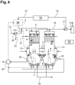
- FIG. 4 is a view of an advantageous oven according to the present invention. As can be seen, this embodiment includes the characteristics of the embodiment according to Figure 3 , but, in addition, it involves a slight transformation in the exterior structure of the oven.
- the tanks 1 and 2 are each provided, below the connecting flue 3 and the peripheral channels 13, with a collector ring 25 which communicates with a withdrawal element 26 so as to allow extraction from the oven of the air from the oven. heated cooling. In this way, part or all of the combustion air can be withdrawn, if necessary also withdrawing a small proportion of the combustion fumes. Indeed, as shown by figure 2a , because the descending gases penetrate deeply into the cooling zone C, the cooling air is pushed towards the outer walls of the furnace where the collector ring is arranged.
- the tanks may also optionally comprise, at the bottom, a central collecting element 27 communicating with the withdrawal element 26 so as to also allow central extraction of heated cooling air, below the connecting flue 3.
- each tank has 4 sides.
- One side 28 of a tank faces a side 29 of the neighboring tank and each tank has a second side 30 and respectively 31 which is opposite to those which face each other.
- the transfer path for gas is a connecting flue 3 which directly connects one tank to the other via their sides 28 and 29.
- the sides 28 to 31 are each provided with a collector tunnel 32 to respectively 35 communicating with a withdrawal element 26 so as to allow extraction of heated cooling air from the oven.
- the cooling air is only pushed by the hot flue gases towards one side.
- the inversion system 16 only opens the collector tunnels 32 and 34. During the following cycle, only the collector tunnels 33 and 35 will be open.
- the same quantity of carbonate rock and the same cooling air flow rates are used as in the conventional oven described above.
- the heated cooling air is extracted from the oven by the withdrawal element 26.
- fuel is introduced such that the formation of 105 Nm 3 /t of CO 2 on combustion is obtained.
- 1330 Nm 3 /t of gaseous effluent is evacuated to the top of tank 2.
- Through the recirculation conduit 18 we take 730 Nm 3 /t of this discharged gaseous effluent, rich in CO 2 .
- a heat exchange can be provided with the part of gaseous effluent recirculated via a heat exchanger 36, before or after mixing with concentrated oxygen.
- the temperature in the connecting flue can be reduced by injecting water at selected locations of the flue and/or the peripheral ring. This added water has no diluting effect on the concentration of CO 2 on dry gas.
- Such arrangements for recovering heat from the heated cooling air, extracted from the oven, using a heat exchanger as well as such devices for injecting CO2 or water into the connecting flue can obviously also be planned with rectangular tank furnaces.
- Table 1 shows the flow rates in a conventional oven and in different oven variants according to the invention and in Table 2 the quantities of the different gaseous elements at the entrance to the ovens.
- 1 means a classic PFRK oven
- 2 and 3 are ovens according to the Figure 3 with variable cooling air flow rates
- 4 and 5 are ovens according to the Figure 4 with and without heat exchanger.
- Table 1 Combustion air Nm 3 /t Cooling air Nm 3 / ⁇ Injection of O 2 Nm 3 / ⁇ Recycled effluent Nm 3 / ⁇ Upper furnace effluent Nm 3 / ⁇ Chimney effluent Nm 3 / ⁇ PD* 1 1120 580 0 - 2250 2250 PD 0 2 0 580 160 830 2070 1240 -13% 3 0 290 200 865 1730 865 -26% 4 0 580 220 730 1330 600 -49% 5 0 580 250 820 1440 620 -39%
- *DP pressure loss Injection of O 2 Nm 3 / ⁇ O 2 kg/ ⁇ N 2 kg/ ⁇ CO 2 kg/ ⁇ O 2 % by mass O 2 stoichiometry kg/ ⁇ Excess of
Landscapes
- Engineering & Computer Science (AREA)
- Chemical & Material Sciences (AREA)
- Mechanical Engineering (AREA)
- General Engineering & Computer Science (AREA)
- Ceramic Engineering (AREA)
- Materials Engineering (AREA)
- Structural Engineering (AREA)
- Organic Chemistry (AREA)
- Physics & Mathematics (AREA)
- Thermal Sciences (AREA)
- Furnace Details (AREA)
- Waste-Gas Treatment And Other Accessory Devices For Furnaces (AREA)
- Feeding, Discharge, Calcimining, Fusing, And Gas-Generation Devices (AREA)
- Vertical, Hearth, Or Arc Furnaces (AREA)
- Curing Cements, Concrete, And Artificial Stone (AREA)
- Tunnel Furnaces (AREA)
- Manufacture And Refinement Of Metals (AREA)
Priority Applications (3)
| Application Number | Priority Date | Filing Date | Title |
|---|---|---|---|
| HRP20250368TT HRP20250368T1 (hr) | 2020-07-03 | 2021-06-28 | Metoda kalciniranja mineralne stijene u vertikalnoj peći s regenerativnim paralelnim protokom i korištena peć |
| SI202130286T SI4324799T1 (sl) | 2020-07-03 | 2021-06-28 | Postopek kalciniranja mineralnih kamnin v regenerativni vertikalni peči z vzporednim tokom in uporabo peči |
| RS20250270A RS66619B1 (sr) | 2020-07-03 | 2021-06-28 | Postupak za kalcinaciju mineralne stene u vertikalnoj šahtnoj regenerativnoj peći sa paralelnim tokom i za to upotrebljena peć |
Applications Claiming Priority (4)
| Application Number | Priority Date | Filing Date | Title |
|---|---|---|---|
| BE202005498 | 2020-07-03 | ||
| PCT/EP2020/083769 WO2022111817A1 (fr) | 2020-11-27 | 2020-11-27 | Procédé de calcination de roche minérale dans un four droit vertical à flux parallèlles régénératif et four mis en oeuvre |
| EP21735319.2A EP4175920B1 (de) | 2020-07-03 | 2021-06-28 | Verfahren zum kalzinieren von mineralgestein in einem regenerativen parallelstrom-vertikalschachtofen und verwendeter ofen |
| PCT/EP2021/067734 WO2022002869A1 (fr) | 2020-07-03 | 2021-06-28 | Procédé de calcination de roche minérale dans un four droit vertical à flux parallèles régénératif et four mis en oeuvre |
Related Parent Applications (2)
| Application Number | Title | Priority Date | Filing Date |
|---|---|---|---|
| EP21735319.2A Division-Into EP4175920B1 (de) | 2020-07-03 | 2021-06-28 | Verfahren zum kalzinieren von mineralgestein in einem regenerativen parallelstrom-vertikalschachtofen und verwendeter ofen |
| EP21735319.2A Division EP4175920B1 (de) | 2020-07-03 | 2021-06-28 | Verfahren zum kalzinieren von mineralgestein in einem regenerativen parallelstrom-vertikalschachtofen und verwendeter ofen |
Publications (3)
| Publication Number | Publication Date |
|---|---|
| EP4324799A2 true EP4324799A2 (de) | 2024-02-21 |
| EP4324799A3 EP4324799A3 (de) | 2024-05-15 |
| EP4324799B1 EP4324799B1 (de) | 2025-01-15 |
Family
ID=76641705
Family Applications (5)
| Application Number | Title | Priority Date | Filing Date |
|---|---|---|---|
| EP23203205.2A Withdrawn EP4282842A3 (de) | 2020-07-03 | 2021-06-28 | Verfahren zum kalzinieren von mineralgestein in einem regenerativen parallelstrom-vertikalschachtofen und verwendeter ofen |
| EP24177308.4A Pending EP4397639A3 (de) | 2020-07-03 | 2021-06-28 | Verfahren zum kalzinieren von mineralgestein in einem vertikalen, regenerativen parallelstromofen und ofen dafür |
| EP23218123.0A Active EP4324799B1 (de) | 2020-07-03 | 2021-06-28 | Verfahren zum kalzinieren von mineralgestein in einem regenerativen parallelstrom-vertikalofen und ofen dafür |
| EP21735319.2A Active EP4175920B1 (de) | 2020-07-03 | 2021-06-28 | Verfahren zum kalzinieren von mineralgestein in einem regenerativen parallelstrom-vertikalschachtofen und verwendeter ofen |
| EP23218138.8A Pending EP4324800A3 (de) | 2020-07-03 | 2021-06-28 | Verfahren zum kalzinieren von mineralgestein in einem regenerativen parallelstrom-vertikalofen und ofen dafür |
Family Applications Before (2)
| Application Number | Title | Priority Date | Filing Date |
|---|---|---|---|
| EP23203205.2A Withdrawn EP4282842A3 (de) | 2020-07-03 | 2021-06-28 | Verfahren zum kalzinieren von mineralgestein in einem regenerativen parallelstrom-vertikalschachtofen und verwendeter ofen |
| EP24177308.4A Pending EP4397639A3 (de) | 2020-07-03 | 2021-06-28 | Verfahren zum kalzinieren von mineralgestein in einem vertikalen, regenerativen parallelstromofen und ofen dafür |
Family Applications After (2)
| Application Number | Title | Priority Date | Filing Date |
|---|---|---|---|
| EP21735319.2A Active EP4175920B1 (de) | 2020-07-03 | 2021-06-28 | Verfahren zum kalzinieren von mineralgestein in einem regenerativen parallelstrom-vertikalschachtofen und verwendeter ofen |
| EP23218138.8A Pending EP4324800A3 (de) | 2020-07-03 | 2021-06-28 | Verfahren zum kalzinieren von mineralgestein in einem regenerativen parallelstrom-vertikalofen und ofen dafür |
Country Status (16)
| Country | Link |
|---|---|
| US (3) | US12344556B2 (de) |
| EP (5) | EP4282842A3 (de) |
| JP (2) | JP7796678B2 (de) |
| CN (1) | CN115803301B (de) |
| BR (1) | BR112022025510A2 (de) |
| CA (1) | CA3183046A1 (de) |
| ES (2) | ES2983795T3 (de) |
| FI (2) | FI4324799T3 (de) |
| HR (2) | HRP20250368T1 (de) |
| HU (2) | HUE067303T2 (de) |
| MX (1) | MX2022016320A (de) |
| PL (2) | PL4175920T3 (de) |
| PT (2) | PT4324799T (de) |
| RS (2) | RS66619B1 (de) |
| SI (2) | SI4324799T1 (de) |
| WO (1) | WO2022002869A1 (de) |
Families Citing this family (17)
| Publication number | Priority date | Publication date | Assignee | Title |
|---|---|---|---|---|
| MX2022016320A (es) | 2020-07-03 | 2023-03-21 | Lhoist Rech Et Developpement Sa | Método de calcinacion de rocas minerales en un horno de camara vertical de flujo paralelo regenerativo y horno utilizado. |
| EP4330614B1 (de) | 2021-04-27 | 2025-06-04 | Maerz Ofenbau AG | Ofen und verfahren zum brennen von karbonatgestein |
| EP4394297A1 (de) * | 2022-12-30 | 2024-07-03 | S.A. Lhoist Recherche Et Developpement | Verfahren zum kalzinieren von karbonisierten mineralsteinen in einem regenerativen ofen mit parallelem fluss und implementierter ofen |
| EP4394298A1 (de) | 2022-12-30 | 2024-07-03 | S.A. Lhoist Recherche Et Developpement | Verfahren zum kalzinieren von karbonisierten mineralsteinen in einem regenerativen ofen mit parallelem fluss und implementierter ofen |
| EP4394296A1 (de) | 2022-12-30 | 2024-07-03 | S.A. Lhoist Recherche Et Developpement | Verfahren zum kalzinieren von karbonisierten mineralsteinen in einem regenerativen ofen mit parallelem fluss und implementierter ofen |
| PL4430010T3 (pl) | 2023-02-01 | 2025-06-09 | Maerz Ofenbau Ag | Piec i sposób wypalania skał węglanowych |
| WO2025196221A1 (en) | 2024-03-20 | 2025-09-25 | S.A. Lhoist Recherche Et Developpement | Method for calcining carbonate mineral stones in a parallel flow regenerative kiln and implemented kiln |
| WO2025195612A1 (en) | 2024-03-20 | 2025-09-25 | S.A. Lhoist Recherche Et Developpement | Method for calcining carbonate mineral stones in a parallel flow regenerative kiln and implemented kiln |
| WO2025242290A1 (en) | 2024-05-21 | 2025-11-27 | S.A. Lhoist Recherche Et Developpement | Method and kiln for calcining carbonate mineral stones in a parallel flow regenerative kiln (pfrk) with rectangular shaft |
| WO2025261597A1 (en) | 2024-06-19 | 2025-12-26 | S.A. Lhoist Recherche Et Developpement | Method and kiln for calcining carbonate mineral stones in a parallel flow regenerative kiln (pfrk) with rectangular shaft |
| WO2025242287A1 (en) | 2024-05-21 | 2025-11-27 | S.A. Lhoist Recherche Et Developpement | Method and kiln for calcining carbonate mineral stones in a parallel flow regenerative kiln (pfrk) with rectangular shaft |
| WO2025242286A1 (en) | 2024-05-21 | 2025-11-27 | S.A. Lhoist Recherche Et Developpement | Method and kiln for calcining carbonate mineral stones in a parallel flow regenerative kiln (pfrk) |
| WO2025242288A1 (en) * | 2024-05-21 | 2025-11-27 | S.A. Lhoist Recherche Et Developpement | Method and kiln for calcining carbonate mineral stones in a parallel flow regenerative kiln (pfrk) |
| WO2025242688A1 (en) | 2024-05-21 | 2025-11-27 | S.A. Lhoist Recherche Et Developpement | Method and kiln for calcining carbonate mineral stones in a parallel flow regenerative kiln (pfrk) with rectangular shaft |
| WO2026092854A1 (en) | 2024-10-31 | 2026-05-07 | S.A. Lhoist Recherche Et Developpement | Method for calcining carbonate mineral stones in a parallel flow regenerative kiln and implemented kiln |
| WO2026139131A1 (en) | 2024-12-24 | 2026-07-02 | S.A. Lhoist Recherche Et Developpement | Method for calcining carbonate mineral stones in a parallel flow regenerative kiln and implemented kiln |
| WO2026158802A1 (en) | 2025-01-27 | 2026-07-30 | S.A. Lhoist Recherche Et Developpement | Process and kiln for calcining mineral rocks with a flue gas treatment unit |
Citations (2)
| Publication number | Priority date | Publication date | Assignee | Title |
|---|---|---|---|---|
| CN105000811A (zh) | 2015-07-24 | 2015-10-28 | 东北大学 | 一种基于co2富集的并流蓄热式石灰窑生产工艺方法 |
| US20200048146A1 (en) | 2017-04-17 | 2020-02-13 | Shiheng ZHANG | Lime kiln apparatus fully recycling co2 |
Family Cites Families (21)
| Publication number | Priority date | Publication date | Assignee | Title |
|---|---|---|---|---|
| AT336473B (de) | 1975-01-17 | 1977-05-10 | Maerz Ofenbau | Verfahren und brennofen zum brennen von grobkornigem und kleinkornigem brenngut in schachtofen |
| CH637760A5 (en) | 1978-09-15 | 1983-08-15 | Maerz Ofenbau | Method for burning mineral, carbonate-containing raw materials in the co-current regenerative shaft furnace |
| JPS6053309B2 (ja) | 1978-12-25 | 1985-11-25 | 富士通株式会社 | 半導体集積回路露光用マスクの製造方法 |
| CH638604A5 (de) * | 1978-12-29 | 1983-09-30 | Maerz Ofenbau | Verfahren zum brennen von mineralischen karbonathaltigen rohstoffen im gleichstrom-regenerativ-schachthofen. |
| JPS5711855A (en) | 1980-06-26 | 1982-01-21 | Nippon Kokan Kk | Lime baking method in parallel flow regeneration type lime baking furnace |
| GB2075163B (en) * | 1980-12-19 | 1983-07-27 | Maerz Ofenbau | Regenerative shaft furnace |
| CH686459A5 (de) * | 1992-03-07 | 1996-03-29 | Maerz Ofenbau | Schachtofen zum Brennen von stuckigem, mineralischem Fuellgut. |
| US6113387A (en) * | 1997-08-14 | 2000-09-05 | Global Stone Corporation | Method and apparatus for controlling kiln |
| DE19845495A1 (de) * | 1997-10-03 | 1999-08-12 | Stingel Egon | Verfahren zum Brennen von carbonhaltigem Gestein unter Erzeugung eines Abgasstroms mit hohem CO2-Gehalt,sowie Doppelschachtofen zur Durchführung der Verfahren |
| DE19843820A1 (de) | 1998-09-24 | 2000-03-30 | Adolf Schmidt | Kalkbrennschachtofen |
| JP2002060254A (ja) | 2000-08-16 | 2002-02-26 | Nkk Corp | シャフト式石灰焼成炉および生石灰の製造方法 |
| AU2003284119A1 (en) * | 2002-10-30 | 2004-06-07 | Krebs And Sisler Lp | A method and apparatus to conduct oxygen-enriched combustion |
| DE10324953A1 (de) * | 2003-06-03 | 2004-12-23 | Maerz Ofenbau Ag | Verfahren zum Brennen von stückigem Brenngut |
| DE102010019330B4 (de) * | 2010-05-05 | 2013-11-07 | Ecoloop Gmbh | Verfahren zur Umwandlung von Carbonaten in Oxide |
| DE102010060866B3 (de) | 2010-11-29 | 2012-02-16 | Maerz Ofenbau Ag | Vorrichtung und Verfahren zum Brennen und/oder Kalzinieren von stückigem Gut |
| EP3037765A1 (de) | 2014-12-26 | 2016-06-29 | L'Air Liquide Société Anonyme pour l'Etude et l'Exploitation des Procédés Georges Claude | Direkt befeuerte geneigte Gegenstrom-Drehöfen und Verwendung davon |
| BE1023010B1 (fr) * | 2015-10-06 | 2016-11-04 | Lhoist Recherche Et Developpement Sa | Procédé de calcination de roche minérale dans un four droit vertical à flux parallèles régénératif et four mis en oeuvre |
| DE102016104076A1 (de) | 2016-03-07 | 2017-09-07 | Maerz Ofenbau Ag | Anlage mit einem Ofen und Verfahren zum Betreiben einer solchen Anlage |
| AT521380B1 (de) * | 2018-10-10 | 2020-01-15 | Michael Schelch Dr | Verfahren und Vorrichtung zur Gewinnung von Wasser aus Luft |
| CN111302675B (zh) * | 2020-04-27 | 2021-11-09 | 垣曲县五龙镁业有限责任公司 | 一种蓄热式节能型双膛竖窑煅烧白云石的方法和系统 |
| MX2022016320A (es) | 2020-07-03 | 2023-03-21 | Lhoist Rech Et Developpement Sa | Método de calcinacion de rocas minerales en un horno de camara vertical de flujo paralelo regenerativo y horno utilizado. |
-
2021
- 2021-06-28 MX MX2022016320A patent/MX2022016320A/es unknown
- 2021-06-28 ES ES21735319T patent/ES2983795T3/es active Active
- 2021-06-28 PL PL21735319.2T patent/PL4175920T3/pl unknown
- 2021-06-28 WO PCT/EP2021/067734 patent/WO2022002869A1/fr not_active Ceased
- 2021-06-28 JP JP2022580377A patent/JP7796678B2/ja active Active
- 2021-06-28 BR BR112022025510A patent/BR112022025510A2/pt unknown
- 2021-06-28 HR HRP20250368TT patent/HRP20250368T1/hr unknown
- 2021-06-28 PT PT232181230T patent/PT4324799T/pt unknown
- 2021-06-28 FI FIEP23218123.0T patent/FI4324799T3/fi active
- 2021-06-28 HR HRP20240989TT patent/HRP20240989T1/hr unknown
- 2021-06-28 ES ES23218123T patent/ES3014775T3/es active Active
- 2021-06-28 RS RS20250270A patent/RS66619B1/sr unknown
- 2021-06-28 FI FIEP21735319.2T patent/FI4175920T3/fi active
- 2021-06-28 HU HUE21735319A patent/HUE067303T2/hu unknown
- 2021-06-28 SI SI202130286T patent/SI4324799T1/sl unknown
- 2021-06-28 CA CA3183046A patent/CA3183046A1/en active Pending
- 2021-06-28 HU HUE23218123A patent/HUE070711T2/hu unknown
- 2021-06-28 RS RS20240801A patent/RS65738B1/sr unknown
- 2021-06-28 EP EP23203205.2A patent/EP4282842A3/de not_active Withdrawn
- 2021-06-28 PL PL23218123.0T patent/PL4324799T3/pl unknown
- 2021-06-28 EP EP24177308.4A patent/EP4397639A3/de active Pending
- 2021-06-28 SI SI202130168T patent/SI4175920T1/sl unknown
- 2021-06-28 EP EP23218123.0A patent/EP4324799B1/de active Active
- 2021-06-28 EP EP21735319.2A patent/EP4175920B1/de active Active
- 2021-06-28 CN CN202180046801.XA patent/CN115803301B/zh active Active
- 2021-06-28 PT PT217353192T patent/PT4175920T/pt unknown
- 2021-06-28 EP EP23218138.8A patent/EP4324800A3/de active Pending
- 2021-06-28 US US18/009,910 patent/US12344556B2/en active Active
-
2025
- 2025-01-17 US US19/029,429 patent/US20250162934A1/en active Pending
- 2025-01-17 US US19/029,912 patent/US20250162935A1/en active Pending
- 2025-12-23 JP JP2025277622A patent/JP2026062783A/ja active Pending
Patent Citations (2)
| Publication number | Priority date | Publication date | Assignee | Title |
|---|---|---|---|---|
| CN105000811A (zh) | 2015-07-24 | 2015-10-28 | 东北大学 | 一种基于co2富集的并流蓄热式石灰窑生产工艺方法 |
| US20200048146A1 (en) | 2017-04-17 | 2020-02-13 | Shiheng ZHANG | Lime kiln apparatus fully recycling co2 |
Also Published As
Similar Documents
| Publication | Publication Date | Title |
|---|---|---|
| EP4175920B1 (de) | Verfahren zum kalzinieren von mineralgestein in einem regenerativen parallelstrom-vertikalschachtofen und verwendeter ofen | |
| EP3359502B1 (de) | Verfahren zum kalzinieren von mineralgestein in einem regenerativen parallelstrom-vertikalschachtofen und ofen dafür | |
| FR2488903A1 (fr) | Procede de production de gaz dans un reacteur a bain de fer | |
| EP2408938A1 (de) | Verfahren zum rezirkulieren von hochofengas und zugehörige vorrichtung | |
| CH694696A5 (it) | Procedimento e dispositivo per la produzione di idrogeno e anidride carbonica da gassificazione di materie prime. | |
| EP4394296A1 (de) | Verfahren zum kalzinieren von karbonisierten mineralsteinen in einem regenerativen ofen mit parallelem fluss und implementierter ofen | |
| RU2708603C1 (ru) | Термохимическая регенерация посредством добавления топлива | |
| EP4643068A1 (de) | Verfahren zum kalzinieren von karbonisierten mineralsteinen in einem regenerativen ofen mit parallelem fluss und implementierter ofen | |
| EP4133212B1 (de) | Verfahren zum kalzinieren von kalk oder dolomit und dafür verwendeter ringschachtofen | |
| WO2022111817A1 (fr) | Procédé de calcination de roche minérale dans un four droit vertical à flux parallèlles régénératif et four mis en oeuvre | |
| EP4506644A1 (de) | Vertikaler gerader ofen mit regenerativem parallelstrom | |
| WO2025242286A1 (en) | Method and kiln for calcining carbonate mineral stones in a parallel flow regenerative kiln (pfrk) | |
| WO2025228775A1 (en) | Decarbonation process of carbonated materials in a multi-shaft vertical kiln | |
| CA3244220A1 (en) | APPARATUS AND PRODUCT MANUFACTURING METHOD |
Legal Events
| Date | Code | Title | Description |
|---|---|---|---|
| REG | Reference to a national code |
Ref country code: HR Ref legal event code: TUEP Ref document number: P20250368T Country of ref document: HR |
|
| PUAI | Public reference made under article 153(3) epc to a published international application that has entered the european phase |
Free format text: ORIGINAL CODE: 0009012 |
|
| STAA | Information on the status of an ep patent application or granted ep patent |
Free format text: STATUS: THE APPLICATION HAS BEEN PUBLISHED |
|
| AC | Divisional application: reference to earlier application |
Ref document number: 4175920 Country of ref document: EP Kind code of ref document: P |
|
| AK | Designated contracting states |
Kind code of ref document: A2 Designated state(s): AL AT BE BG CH CY CZ DE DK EE ES FI FR GB GR HR HU IE IS IT LI LT LU LV MC MK MT NL NO PL PT RO RS SE SI SK SM TR |
|
| PUAL | Search report despatched |
Free format text: ORIGINAL CODE: 0009013 |
|
| AK | Designated contracting states |
Kind code of ref document: A3 Designated state(s): AL AT BE BG CH CY CZ DE DK EE ES FI FR GB GR HR HU IE IS IT LI LT LU LV MC MK MT NL NO PL PT RO RS SE SI SK SM TR |
|
| RIC1 | Information provided on ipc code assigned before grant |
Ipc: C04B 2/12 20060101AFI20240408BHEP |
|
| STAA | Information on the status of an ep patent application or granted ep patent |
Free format text: STATUS: REQUEST FOR EXAMINATION WAS MADE |
|
| 17P | Request for examination filed |
Effective date: 20240611 |
|
| RBV | Designated contracting states (corrected) |
Designated state(s): AL AT BE BG CH CY CZ DE DK EE ES FI FR GB GR HR HU IE IS IT LI LT LU LV MC MK MT NL NO PL PT RO RS SE SI SK SM TR |
|
| GRAP | Despatch of communication of intention to grant a patent |
Free format text: ORIGINAL CODE: EPIDOSNIGR1 |
|
| STAA | Information on the status of an ep patent application or granted ep patent |
Free format text: STATUS: GRANT OF PATENT IS INTENDED |
|
| INTG | Intention to grant announced |
Effective date: 20240926 |
|
| GRAS | Grant fee paid |
Free format text: ORIGINAL CODE: EPIDOSNIGR3 |
|
| GRAA | (expected) grant |
Free format text: ORIGINAL CODE: 0009210 |
|
| STAA | Information on the status of an ep patent application or granted ep patent |
Free format text: STATUS: THE PATENT HAS BEEN GRANTED |
|
| AC | Divisional application: reference to earlier application |
Ref document number: 4175920 Country of ref document: EP Kind code of ref document: P |
|
| AK | Designated contracting states |
Kind code of ref document: B1 Designated state(s): AL AT BE BG CH CY CZ DE DK EE ES FI FR GB GR HR HU IE IS IT LI LT LU LV MC MK MT NL NO PL PT RO RS SE SI SK SM TR |
|
| REG | Reference to a national code |
Ref country code: CH Ref legal event code: EP Ref country code: GB Ref legal event code: FG4D Free format text: NOT ENGLISH |
|
| REG | Reference to a national code |
Ref country code: DE Ref legal event code: R096 Ref document number: 602021025022 Country of ref document: DE |
|
| REG | Reference to a national code |
Ref country code: IE Ref legal event code: FG4D Free format text: LANGUAGE OF EP DOCUMENT: FRENCH |
|
| REG | Reference to a national code |
Ref country code: PT Ref legal event code: SC4A Ref document number: 4324799 Country of ref document: PT Date of ref document: 20250314 Kind code of ref document: T Free format text: AVAILABILITY OF NATIONAL TRANSLATION Effective date: 20250310 |
|
| P01 | Opt-out of the competence of the unified patent court (upc) registered |
Free format text: CASE NUMBER: APP_7490/2025 Effective date: 20250213 |
|
| REG | Reference to a national code |
Ref country code: FI Ref legal event code: FGE |
|
| REG | Reference to a national code |
Ref country code: SE Ref legal event code: TRGR |
|
| REG | Reference to a national code |
Ref country code: ES Ref legal event code: FG2A Ref document number: 3014775 Country of ref document: ES Kind code of ref document: T3 Effective date: 20250424 |
|
| REG | Reference to a national code |
Ref country code: HR Ref legal event code: T1PR Ref document number: P20250368 Country of ref document: HR |
|
| REG | Reference to a national code |
Ref country code: NL Ref legal event code: MP Effective date: 20250115 |
|
| REG | Reference to a national code |
Ref country code: SK Ref legal event code: T3 Ref document number: E 46157 Country of ref document: SK |
|
| PG25 | Lapsed in a contracting state [announced via postgrant information from national office to epo] |
Ref country code: NL Free format text: LAPSE BECAUSE OF FAILURE TO SUBMIT A TRANSLATION OF THE DESCRIPTION OR TO PAY THE FEE WITHIN THE PRESCRIBED TIME-LIMIT Effective date: 20250115 |
|
| REG | Reference to a national code |
Ref country code: HU Ref legal event code: AG4A Ref document number: E070711 Country of ref document: HU |
|
| REG | Reference to a national code |
Ref country code: LT Ref legal event code: MG9D |
|
| PG25 | Lapsed in a contracting state [announced via postgrant information from national office to epo] |
Ref country code: IS Free format text: LAPSE BECAUSE OF FAILURE TO SUBMIT A TRANSLATION OF THE DESCRIPTION OR TO PAY THE FEE WITHIN THE PRESCRIBED TIME-LIMIT Effective date: 20250515 |
|
| PG25 | Lapsed in a contracting state [announced via postgrant information from national office to epo] |
Ref country code: LV Free format text: LAPSE BECAUSE OF FAILURE TO SUBMIT A TRANSLATION OF THE DESCRIPTION OR TO PAY THE FEE WITHIN THE PRESCRIBED TIME-LIMIT Effective date: 20250115 |
|
| REG | Reference to a national code |
Ref country code: HR Ref legal event code: ODRP Ref document number: P20250368 Country of ref document: HR Payment date: 20250618 Year of fee payment: 5 |
|
| PG25 | Lapsed in a contracting state [announced via postgrant information from national office to epo] |
Ref country code: GR Free format text: LAPSE BECAUSE OF FAILURE TO SUBMIT A TRANSLATION OF THE DESCRIPTION OR TO PAY THE FEE WITHIN THE PRESCRIBED TIME-LIMIT Effective date: 20250416 |
|
| PGFP | Annual fee paid to national office [announced via postgrant information from national office to epo] |
Ref country code: SE Payment date: 20250624 Year of fee payment: 5 |
|
| REG | Reference to a national code |
Ref country code: DE Ref legal event code: R026 Ref document number: 602021025022 Country of ref document: DE |
|
| PLBI | Opposition filed |
Free format text: ORIGINAL CODE: 0009260 |
|
| PG25 | Lapsed in a contracting state [announced via postgrant information from national office to epo] |
Ref country code: SM Free format text: LAPSE BECAUSE OF FAILURE TO SUBMIT A TRANSLATION OF THE DESCRIPTION OR TO PAY THE FEE WITHIN THE PRESCRIBED TIME-LIMIT Effective date: 20250115 |
|
| REG | Reference to a national code |
Ref country code: CH Ref legal event code: L10 Free format text: ST27 STATUS EVENT CODE: U-0-0-L10-L00 (AS PROVIDED BY THE NATIONAL OFFICE) Effective date: 20251008 |
|
| PGFP | Annual fee paid to national office [announced via postgrant information from national office to epo] |
Ref country code: ES Payment date: 20250918 Year of fee payment: 5 |
|
| PG25 | Lapsed in a contracting state [announced via postgrant information from national office to epo] |
Ref country code: DK Free format text: LAPSE BECAUSE OF FAILURE TO SUBMIT A TRANSLATION OF THE DESCRIPTION OR TO PAY THE FEE WITHIN THE PRESCRIBED TIME-LIMIT Effective date: 20250115 |
|
| PLBI | Opposition filed |
Free format text: ORIGINAL CODE: 0009260 |
|
| PGFP | Annual fee paid to national office [announced via postgrant information from national office to epo] |
Ref country code: CH Payment date: 20250701 Year of fee payment: 5 |
|
| PG25 | Lapsed in a contracting state [announced via postgrant information from national office to epo] |
Ref country code: EE Free format text: LAPSE BECAUSE OF FAILURE TO SUBMIT A TRANSLATION OF THE DESCRIPTION OR TO PAY THE FEE WITHIN THE PRESCRIBED TIME-LIMIT Effective date: 20250115 |
|
| REG | Reference to a national code |
Ref country code: CH Ref legal event code: L10 Free format text: ST27 STATUS EVENT CODE: U-0-0-L10-L00 (AS PROVIDED BY THE NATIONAL OFFICE) Effective date: 20251022 |
|
| PLAX | Notice of opposition and request to file observation + time limit sent |
Free format text: ORIGINAL CODE: EPIDOSNOBS2 |
|
| 26 | Opposition filed |
Opponent name: CARMEUSE TECHNOLOGIES S.A. Effective date: 20250929 |
|
| 26 | Opposition filed |
Opponent name: MAERZ OFENBAU AG Effective date: 20251011 Opponent name: FELS-WERKE GMBH Effective date: 20251013 |
|
| PG25 | Lapsed in a contracting state [announced via postgrant information from national office to epo] |
Ref country code: MC Free format text: LAPSE BECAUSE OF FAILURE TO SUBMIT A TRANSLATION OF THE DESCRIPTION OR TO PAY THE FEE WITHIN THE PRESCRIBED TIME-LIMIT Effective date: 20250115 |
|
| PG25 | Lapsed in a contracting state [announced via postgrant information from national office to epo] |
Ref country code: LU Free format text: LAPSE BECAUSE OF NON-PAYMENT OF DUE FEES Effective date: 20250628 |
|
| PLBB | Reply of patent proprietor to notice(s) of opposition received |
Free format text: ORIGINAL CODE: EPIDOSNOBS3 |
|
| REG | Reference to a national code |
Ref country code: AT Ref legal event code: UEP Ref document number: 1759796 Country of ref document: AT Kind code of ref document: T Effective date: 20250115 |
|
| PG25 | Lapsed in a contracting state [announced via postgrant information from national office to epo] |
Ref country code: LT Free format text: LAPSE BECAUSE OF FAILURE TO SUBMIT A TRANSLATION OF THE DESCRIPTION OR TO PAY THE FEE WITHIN THE PRESCRIBED TIME-LIMIT Effective date: 20250115 |
|
| REG | Reference to a national code |
Ref country code: CH Ref legal event code: U11 Free format text: ST27 STATUS EVENT CODE: U-0-0-U10-U11 (AS PROVIDED BY THE NATIONAL OFFICE) Effective date: 20260701 |
|
| REG | Reference to a national code |
Ref country code: HR Ref legal event code: ODRP Ref document number: P20250368 Country of ref document: HR Payment date: 20260608 Year of fee payment: 6 |
|
| PGFP | Annual fee paid to national office [announced via postgrant information from national office to epo] |
Ref country code: GB Payment date: 20260622 Year of fee payment: 6 Ref country code: RS Payment date: 20260609 Year of fee payment: 6 Ref country code: PL Payment date: 20260609 Year of fee payment: 6 |
|
| PGFP | Annual fee paid to national office [announced via postgrant information from national office to epo] |
Ref country code: IT Payment date: 20260615 Year of fee payment: 6 |
|
| PGFP | Annual fee paid to national office [announced via postgrant information from national office to epo] |
Ref country code: DE Payment date: 20260623 Year of fee payment: 6 |
|
| PGFP | Annual fee paid to national office [announced via postgrant information from national office to epo] |
Ref country code: NO Payment date: 20260624 Year of fee payment: 6 |
|
| PGFP | Annual fee paid to national office [announced via postgrant information from national office to epo] |
Ref country code: AT Payment date: 20260622 Year of fee payment: 6 Ref country code: FI Payment date: 20260622 Year of fee payment: 6 |
|
| PGFP | Annual fee paid to national office [announced via postgrant information from national office to epo] |
Ref country code: RO Payment date: 20260622 Year of fee payment: 6 Ref country code: HU Payment date: 20260622 Year of fee payment: 6 Ref country code: IE Payment date: 20260623 Year of fee payment: 6 Ref country code: BE Payment date: 20260623 Year of fee payment: 6 |
|
| PGFP | Annual fee paid to national office [announced via postgrant information from national office to epo] |
Ref country code: HR Payment date: 20260608 Year of fee payment: 6 |
|
| PLAB | Opposition data, opponent's data or that of the opponent's representative modified |
Free format text: ORIGINAL CODE: 0009299OPPO |
|
| PGFP | Annual fee paid to national office [announced via postgrant information from national office to epo] |
Ref country code: PT Payment date: 20260609 Year of fee payment: 6 |
|
| PGFP | Annual fee paid to national office [announced via postgrant information from national office to epo] |
Ref country code: CZ Payment date: 20260610 Year of fee payment: 6 Ref country code: TR Payment date: 20260608 Year of fee payment: 6 |
|
| REG | Reference to a national code |
Ref country code: CH Ref legal event code: L10 Free format text: ST27 STATUS EVENT CODE: U-0-0-L10-L00 (AS PROVIDED BY THE NATIONAL OFFICE) Effective date: 20260722 |
|
| PGFP | Annual fee paid to national office [announced via postgrant information from national office to epo] |
Ref country code: FR Payment date: 20260623 Year of fee payment: 6 |
|
| PGFP | Annual fee paid to national office [announced via postgrant information from national office to epo] |
Ref country code: SK Payment date: 20260608 Year of fee payment: 6 |
|
| PGFP | Annual fee paid to national office [announced via postgrant information from national office to epo] |
Ref country code: BG Payment date: 20260618 Year of fee payment: 6 |
|
| PGFP | Annual fee paid to national office [announced via postgrant information from national office to epo] |
Ref country code: SI Payment date: 20260609 Year of fee payment: 6 |
|
| PG25 | Lapsed in a contracting state [announced via postgrant information from national office to epo] |
Ref country code: CY Free format text: LAPSE BECAUSE OF FAILURE TO SUBMIT A TRANSLATION OF THE DESCRIPTION OR TO PAY THE FEE WITHIN THE PRESCRIBED TIME-LIMIT Effective date: 20250115 |