EP4324943A1 - Kornorientiertes elektromagnetisches stahlblech - Google Patents
Kornorientiertes elektromagnetisches stahlblech Download PDFInfo
- Publication number
- EP4324943A1 EP4324943A1 EP22815922.4A EP22815922A EP4324943A1 EP 4324943 A1 EP4324943 A1 EP 4324943A1 EP 22815922 A EP22815922 A EP 22815922A EP 4324943 A1 EP4324943 A1 EP 4324943A1
- Authority
- EP
- European Patent Office
- Prior art keywords
- steel sheet
- grain
- closure
- less
- oriented electrical
- Prior art date
- Legal status (The legal status is an assumption and is not a legal conclusion. Google has not performed a legal analysis and makes no representation as to the accuracy of the status listed.)
- Pending
Links
Images



Classifications
-
- C—CHEMISTRY; METALLURGY
- C21—METALLURGY OF IRON
- C21D—MODIFYING THE PHYSICAL STRUCTURE OF FERROUS METALS; GENERAL DEVICES FOR HEAT TREATMENT OF FERROUS OR NON-FERROUS METALS OR ALLOYS; MAKING METAL MALLEABLE, e.g. BY DECARBURISATION OR TEMPERING
- C21D9/00—Heat treatment, e.g. annealing, hardening, quenching or tempering, adapted for particular articles; Furnaces therefor
- C21D9/46—Heat treatment, e.g. annealing, hardening, quenching or tempering, adapted for particular articles; Furnaces therefor for sheet metals
-
- C—CHEMISTRY; METALLURGY
- C22—METALLURGY; FERROUS OR NON-FERROUS ALLOYS; TREATMENT OF ALLOYS OR NON-FERROUS METALS
- C22C—ALLOYS
- C22C38/00—Ferrous alloys, e.g. steel alloys
- C22C38/02—Ferrous alloys, e.g. steel alloys containing silicon
-
- B—PERFORMING OPERATIONS; TRANSPORTING
- B23—MACHINE TOOLS; METAL-WORKING NOT OTHERWISE PROVIDED FOR
- B23K—SOLDERING OR UNSOLDERING; WELDING; CLADDING OR PLATING BY SOLDERING OR WELDING; CUTTING BY APPLYING HEAT LOCALLY, e.g. FLAME CUTTING; WORKING BY LASER BEAM
- B23K26/00—Working by laser beam, e.g. welding, cutting or boring
- B23K26/02—Positioning or observing the workpiece, e.g. with respect to the point of impact; Aligning, aiming or focusing the laser beam
- B23K26/06—Shaping the laser beam, e.g. by masks or multi-focusing
- B23K26/073—Shaping the laser spot
-
- B—PERFORMING OPERATIONS; TRANSPORTING
- B23—MACHINE TOOLS; METAL-WORKING NOT OTHERWISE PROVIDED FOR
- B23K—SOLDERING OR UNSOLDERING; WELDING; CLADDING OR PLATING BY SOLDERING OR WELDING; CUTTING BY APPLYING HEAT LOCALLY, e.g. FLAME CUTTING; WORKING BY LASER BEAM
- B23K26/00—Working by laser beam, e.g. welding, cutting or boring
- B23K26/08—Devices involving relative movement between laser beam and workpiece
- B23K26/083—Devices involving movement of the workpiece in at least one axial direction
- B23K26/0838—Devices involving movement of the workpiece in at least one axial direction by using an endless conveyor belt
-
- B—PERFORMING OPERATIONS; TRANSPORTING
- B23—MACHINE TOOLS; METAL-WORKING NOT OTHERWISE PROVIDED FOR
- B23K—SOLDERING OR UNSOLDERING; WELDING; CLADDING OR PLATING BY SOLDERING OR WELDING; CUTTING BY APPLYING HEAT LOCALLY, e.g. FLAME CUTTING; WORKING BY LASER BEAM
- B23K26/00—Working by laser beam, e.g. welding, cutting or boring
- B23K26/352—Working by laser beam, e.g. welding, cutting or boring for surface treatment
- B23K26/355—Texturing
-
- C—CHEMISTRY; METALLURGY
- C21—METALLURGY OF IRON
- C21D—MODIFYING THE PHYSICAL STRUCTURE OF FERROUS METALS; GENERAL DEVICES FOR HEAT TREATMENT OF FERROUS OR NON-FERROUS METALS OR ALLOYS; MAKING METAL MALLEABLE, e.g. BY DECARBURISATION OR TEMPERING
- C21D8/00—Modifying the physical properties of ferrous metals or ferrous alloys by deformation combined with, or followed by, heat treatment
- C21D8/12—Modifying the physical properties of ferrous metals or ferrous alloys by deformation combined with, or followed by, heat treatment during manufacturing of articles with special electromagnetic properties
- C21D8/1294—Modifying the physical properties of ferrous metals or ferrous alloys by deformation combined with, or followed by, heat treatment during manufacturing of articles with special electromagnetic properties involving a localised treatment
-
- C—CHEMISTRY; METALLURGY
- C22—METALLURGY; FERROUS OR NON-FERROUS ALLOYS; TREATMENT OF ALLOYS OR NON-FERROUS METALS
- C22C—ALLOYS
- C22C38/00—Ferrous alloys, e.g. steel alloys
- C22C38/001—Ferrous alloys, e.g. steel alloys containing N
-
- C—CHEMISTRY; METALLURGY
- C22—METALLURGY; FERROUS OR NON-FERROUS ALLOYS; TREATMENT OF ALLOYS OR NON-FERROUS METALS
- C22C—ALLOYS
- C22C38/00—Ferrous alloys, e.g. steel alloys
- C22C38/04—Ferrous alloys, e.g. steel alloys containing manganese
-
- C—CHEMISTRY; METALLURGY
- C22—METALLURGY; FERROUS OR NON-FERROUS ALLOYS; TREATMENT OF ALLOYS OR NON-FERROUS METALS
- C22C—ALLOYS
- C22C38/00—Ferrous alloys, e.g. steel alloys
- C22C38/06—Ferrous alloys, e.g. steel alloys containing aluminium
-
- C—CHEMISTRY; METALLURGY
- C22—METALLURGY; FERROUS OR NON-FERROUS ALLOYS; TREATMENT OF ALLOYS OR NON-FERROUS METALS
- C22C—ALLOYS
- C22C38/00—Ferrous alloys, e.g. steel alloys
- C22C38/08—Ferrous alloys, e.g. steel alloys containing nickel
-
- C—CHEMISTRY; METALLURGY
- C22—METALLURGY; FERROUS OR NON-FERROUS ALLOYS; TREATMENT OF ALLOYS OR NON-FERROUS METALS
- C22C—ALLOYS
- C22C38/00—Ferrous alloys, e.g. steel alloys
- C22C38/60—Ferrous alloys, e.g. steel alloys containing lead, selenium, tellurium, or antimony, or more than 0.04% by weight of sulfur
-
- H—ELECTRICITY
- H01—ELECTRIC ELEMENTS
- H01F—MAGNETS; INDUCTANCES; TRANSFORMERS; SELECTION OF MATERIALS FOR THEIR MAGNETIC PROPERTIES
- H01F1/00—Magnets or magnetic bodies characterised by the magnetic materials therefor; Selection of materials for their magnetic properties
- H01F1/01—Magnets or magnetic bodies characterised by the magnetic materials therefor; Selection of materials for their magnetic properties of inorganic materials
- H01F1/03—Magnets or magnetic bodies characterised by the magnetic materials therefor; Selection of materials for their magnetic properties of inorganic materials characterised by their coercivity
- H01F1/12—Magnets or magnetic bodies characterised by the magnetic materials therefor; Selection of materials for their magnetic properties of inorganic materials characterised by their coercivity of soft-magnetic materials
- H01F1/14—Magnets or magnetic bodies characterised by the magnetic materials therefor; Selection of materials for their magnetic properties of inorganic materials characterised by their coercivity of soft-magnetic materials metals or alloys
- H01F1/147—Alloys characterised by their composition
-
- H—ELECTRICITY
- H01—ELECTRIC ELEMENTS
- H01F—MAGNETS; INDUCTANCES; TRANSFORMERS; SELECTION OF MATERIALS FOR THEIR MAGNETIC PROPERTIES
- H01F1/00—Magnets or magnetic bodies characterised by the magnetic materials therefor; Selection of materials for their magnetic properties
- H01F1/01—Magnets or magnetic bodies characterised by the magnetic materials therefor; Selection of materials for their magnetic properties of inorganic materials
- H01F1/03—Magnets or magnetic bodies characterised by the magnetic materials therefor; Selection of materials for their magnetic properties of inorganic materials characterised by their coercivity
- H01F1/12—Magnets or magnetic bodies characterised by the magnetic materials therefor; Selection of materials for their magnetic properties of inorganic materials characterised by their coercivity of soft-magnetic materials
- H01F1/14—Magnets or magnetic bodies characterised by the magnetic materials therefor; Selection of materials for their magnetic properties of inorganic materials characterised by their coercivity of soft-magnetic materials metals or alloys
- H01F1/16—Magnets or magnetic bodies characterised by the magnetic materials therefor; Selection of materials for their magnetic properties of inorganic materials characterised by their coercivity of soft-magnetic materials metals or alloys in the form of sheets
-
- B—PERFORMING OPERATIONS; TRANSPORTING
- B23—MACHINE TOOLS; METAL-WORKING NOT OTHERWISE PROVIDED FOR
- B23K—SOLDERING OR UNSOLDERING; WELDING; CLADDING OR PLATING BY SOLDERING OR WELDING; CUTTING BY APPLYING HEAT LOCALLY, e.g. FLAME CUTTING; WORKING BY LASER BEAM
- B23K2101/00—Articles made by soldering, welding or cutting
- B23K2101/18—Sheet panels
-
- B—PERFORMING OPERATIONS; TRANSPORTING
- B23—MACHINE TOOLS; METAL-WORKING NOT OTHERWISE PROVIDED FOR
- B23K—SOLDERING OR UNSOLDERING; WELDING; CLADDING OR PLATING BY SOLDERING OR WELDING; CUTTING BY APPLYING HEAT LOCALLY, e.g. FLAME CUTTING; WORKING BY LASER BEAM
- B23K2103/00—Materials to be soldered, welded or cut
- B23K2103/02—Iron or ferrous alloys
- B23K2103/04—Steel or steel alloys
-
- B—PERFORMING OPERATIONS; TRANSPORTING
- B23—MACHINE TOOLS; METAL-WORKING NOT OTHERWISE PROVIDED FOR
- B23K—SOLDERING OR UNSOLDERING; WELDING; CLADDING OR PLATING BY SOLDERING OR WELDING; CUTTING BY APPLYING HEAT LOCALLY, e.g. FLAME CUTTING; WORKING BY LASER BEAM
- B23K26/00—Working by laser beam, e.g. welding, cutting or boring
- B23K26/02—Positioning or observing the workpiece, e.g. with respect to the point of impact; Aligning, aiming or focusing the laser beam
- B23K26/06—Shaping the laser beam, e.g. by masks or multi-focusing
- B23K26/064—Shaping the laser beam, e.g. by masks or multi-focusing by means of optical elements, e.g. lenses, mirrors or prisms
-
- C—CHEMISTRY; METALLURGY
- C21—METALLURGY OF IRON
- C21D—MODIFYING THE PHYSICAL STRUCTURE OF FERROUS METALS; GENERAL DEVICES FOR HEAT TREATMENT OF FERROUS OR NON-FERROUS METALS OR ALLOYS; MAKING METAL MALLEABLE, e.g. BY DECARBURISATION OR TEMPERING
- C21D2201/00—Treatment for obtaining particular effects
- C21D2201/05—Grain orientation
Definitions
- This disclosure relates to a grain-oriented electrical steel sheet that is suitable as an iron core material for transformers and the like.
- Grain-oriented electrical steel sheets are used, for example, as iron core material for transformers.
- energy loss and noise need to be suppressed, and the iron loss of the grain-oriented electrical steel sheet affects the energy loss, while its magnetostrictive property affects the noise.
- the iron loss of the grain-oriented electrical steel sheet affects the energy loss, while its magnetostrictive property affects the noise.
- the iron loss of grain-oriented electrical steel sheets is mainly composed of hysteresis loss and eddy current loss.
- Methods to reduce hysteresis loss have been developed, such as forming crystal grains highly aligned with the (110)[001] orientation, called Goss orientation, in the rolling direction of steel sheets, reducing impurities in steel sheets, and so on.
- Methods to improve eddy current losses have been developed, such as increasing the electrical resistance of steel sheets by adding Si, applying film tension in the rolling direction of steel sheets, and so on.
- Magnetic domain refining technology has been developed as a method to pursue even lower iron loss in grain-oriented electrical steel sheets.
- Magnetic domain refining is a technique to reduce iron loss, especially eddy current loss, of grain-oriented electrical steel sheets by physically introducing non-uniformity of magnetic flux into the steel sheets after final annealing or baking of insulating coating by forming grooves or introducing local strain, etc., to refine the width of 180° magnetic domains (main magnetic domains) formed along the rolling direction.
- JP H6-22179 B proposes a technology to reduce iron loss from 0.80 W/kg or more to 0.70 W/kg or less by introducing linear grooves of 300 ⁇ m or less in width and 100 ⁇ m or less in depth on the steel sheet surface.
- JP H7-192891 A proposes a method to reduce the iron loss (W 17/50 ), with a maximum magnetic flux density of 1.7 T when excited at a frequency of 50 Hz, to 0.680 W/kg for a steel sheet that has a magnetic flux density (Bs) of 1.935 T when excited with a magnetizing force of 800 A/m, by irradiating a plasma flame in the width direction of the steel sheet surface after secondary recrystallization and introducing local thermal strain.
- the method of forming linear grooves as described in PTL 1 is called heat-resistant type magnetic domain refining, because the magnetic domain refining effect is not lost even by performing stress relief annealing after iron core formation.
- the method of introducing thermal strain as described in PTL 2 is referred to as non-heat-resistant type magnetic domain refining, because the effect of introducing thermal strain is no longer obtained by stress relief annealing.
- non-heat-resistant type magnetic domain refining can significantly reduce eddy current losses by introducing local strain in steel sheets.
- non-heat-resistant type magnetic domain refining is known to cause degradation of hysteresis loss property and magnetostriction due to the introduction of such strain.
- closure domains greatly affects the ability of non-heat-resistant magnetic domain refining, it is advantageous to optimize the pattern of introduction of closure domains to provide grain-oriented electrical steel sheets that exhibit excellent transformer characteristics and have both low iron loss and low magnetostriction. To this end, it is necessary to have an accurate understanding of closure domains. Until now, many means of measuring the three-dimensional distribution of closure domains have been proposed, but they all have the following problems.
- JP 2016-166419 A (PTL 3) describes a technique for observing the cross section of a steel sheet sheared along the rolling direction using a Kerr effect microscope.
- PTL 3 JP 2016-166419 A
- Such a measurement method has problems in that strain is included in the observation plane due to mirror polishing, which is necessary for the preparation of a sample for observation, and that the magnetic domain structure at the observation point becomes different from the actual one upon exposure of a cross-section. More importantly, the observation provides only a small portion of the closure domains introduced into the steel sheet, which is insufficient for estimating the three-dimensional distribution.
- WO 2020/158732 A (PTL 4) describes a method of estimating the amount of closure domains introduced from the difference waveforms of the magnetostriction waveforms before and after stress relief annealing, focusing on the time-magnetostriction waveform when excited up to 1.7 T.
- PTL 4 describes a method of estimating the amount of closure domains introduced from the difference waveforms of the magnetostriction waveforms before and after stress relief annealing, focusing on the time-magnetostriction waveform when excited up to 1.7 T.
- it is difficult to accurately estimate the amount of closure domains introduced because not only magnetostrictive vibration due to the annihilation of closure domains but also magnetostrictive vibration components due to magnetization rotation of the main magnetic domains caused by misorientation of crystals from the rolling direction are included.
- closure domains As mentioned above, although there is a need for a means to optimize the distribution of closure domains in order to develop grain-oriented electrical steel sheets with excellent iron loss and noise properties, it has been difficult to meet the higher performance requirements in recent years by identifying closure domains based on the methods described in PTLs 3 and 4.
- An object of the present disclosure is to provide a grain-oriented electrical steel sheet that exhibits excellent transformer characteristics and that has both low iron loss and low magnetostriction properties by using the means.
- the present inventors made intensive studies on the solution to address the above-described issues.
- Non-heat-resistant type magnetic domain refining is a technique to control magnetic domains by introducing strain into steel sheets to create a localized stress field. Therefore, in order to develop a grain-oriented electrical steel sheet with lower iron loss and noise than before, the present inventors focused on the distribution of stress introduced into the steel sheet and the magnetization direction of closure domains, and investigated their effects on magnetic properties.
- energy beam is irradiated to a grain-oriented electrical steel sheet in the direction orthogonal to the rolling direction (sheet transverse direction) to introduce localized thermal strain.
- compressive stress in the rolling direction remains at the energy beam irradiation points.
- crystal grains with Goss orientation (110)[001], which is the easy magnetization axis, are highly aligned with the rolling direction. Accordingly, when compressive stress is applied in the rolling direction, magnetic domains with a magnetization direction along the sheet transverse direction (i.e., closure domains) are formed due to the magneto-elastic effect.
- the magneto-elastic effect is a phenomenon that upon application of tensile stress, a grain-oriented electrical steel sheet becomes energetically stable in the direction of the tensile stress, and upon application of compressive stress, it becomes energetically stable in the direction orthogonal to the compressive stress.
- the closure domains promote the reduction of eddy current losses.
- the hysteresis loss will increase as a result of the movement of magnetic domain walls due to magnetization being pinned by the strain.
- magnetization in the rolling direction is weakened, i.e., the steel sheet is magnetized in the direction 180° opposite to the direction in which the steel sheet was initially magnetized. Then, the anisotropy in the rolling direction due to magnetization decreases, and the anisotropy in the sheet transverse direction due to compressive stress becomes dominant again, resulting in closure domains being generated again.
- the grain-oriented electrical steel sheet then elongates in the sheet transverse direction and contracts in the rolling direction.
- magnetostrictive vibration of steel sheets includes not only the generation and annihilation behavior of closure domains as mentioned above, but also a component of magnetization rotation caused by the displacement of crystal orientation from the rolling direction.
- FIG. 1 illustrates the effect of magnetic domains on the butterfly curve with the maximum excitation magnetic flux density B ranging from 0 T to 1.7 T, obtained by magnetic domain observation.
- the annihilation of closure domains begins when the excitation magnetic flux density reaches 1.0 T or more, and when the magnetic flux density exceeds 1.5 T, the slope of the butterfly curve begins to decrease because the elongation of the steel sheet due to the loss of closure domains is combined with the contraction of the steel sheet due to magnetization rotation.
- the present inventors found that the amount of steel sheet elongation ⁇ (hereinafter simply ⁇ ) with the magnetic flux density B ranging from 1.0 T to 1.5 T corresponds well to the total amount of closure domains.
- the distribution of closure domains can be estimated very accurately from this ⁇ value, the length of the closure domains in the rolling direction observed from the steel sheet surface (i.e., a closure domain width), and the interval between the closure domains introduced into the steel sheet (i.e., the number of lines of closure domains). Based on this estimation, it was revealed that by controlling the closure domain width and the number of lines of closure domains within the appropriate ranges, it is possible to produce a grain-oriented electrical steel sheet with both lower iron loss and lower noise than before.
- the present inventors conducted further studies to investigate the appropriate ranges of ⁇ and closure domain width, and the appropriate range of the interval at which closure domains are formed (also referred to herein as the "formation interval of closure domains"), respectively.
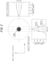
- the magnetic domain refining treatment was performed by laser beam irradiation with a profile that was arranged to have a steep energy distribution by cutting off beam regions with energy intensity below a certain level with respect to the maximum intensity, as illustrated in FIG. 2 .
- a 0.23-mm-thick strip of a grain-oriented electrical steel sheet produced by a known method was irradiated with laser beam with a Gaussian-shaped profile at various power outputs.
- laser beam with a beam diameter (i.e., full width at half maximum) of 20 ⁇ m, 100 ⁇ m, or 200 ⁇ m was used, and passed through an aperture with a hole diameter of 8 mm, 10 mm, or 12 mm placed just before the lens for converging the laser beam (distance from the converging lens: 20 mm), with the profile illustrated in FIG. 2 , and the irradiation interval was set to 5 mm.
- beam regions where energy was 30 % or less of the maximum intensity value were cut off.
- laser beam with a Gaussian-shaped profile refers to a laser beam such that the intensity distribution (profile) obtained by scanning the laser beam in a certain direction with respect to a profiler with a linear slit is a Gaussian distribution.
- a portion of the strip of a grain-oriented electrical steel sheet thus obtained was cut out, and the magnetostrictive vibration waveform when the strip was sinusoidally AC magnetized at 1.5 T and 50 Hz was measured using a laser Doppler magnetostrictive vibrometer to obtain a butterfly curve.
- the magnetic domain pattern on the steel sheet surface was transferred and the width of the closure domains formed in the direction across the rolling direction was measured.
- a three-phase transformer (iron core weight: 500 kg) was fabricated using a grain-oriented electrical steel sheet sample subjected to the magnetic domain refining treatment, and the iron loss property was measured when the magnetic flux density at the iron core legs was 1.7 T at the frequency of 50 Hz.
- the iron loss properties at 1.7 T and 50 Hz were measured using a wattmeter to determine the no-load loss.
- this model transformer was excited in a soundproof room at the maximum magnetic flux density Bm of 1.7 T and the frequency of 50 Hz, and the noise level (dBA) was measured using a sound level meter.
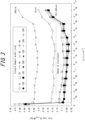
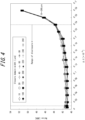
- a high iron-loss-reducing effect can be obtained in a case where ⁇ is in the range of 0.010 ⁇ 10 -6 to 0.240 ⁇ 10 -6 and the closure domain width is in the range of 20 ⁇ m to 240 ⁇ m.
- ⁇ is in the range of 0.010 ⁇ 10 -6 to 0.200 ⁇ 10 -6 and the closure domain width is in the range of 50 ⁇ m to 240 ⁇ m
- a particularly high iron-loss-reducing effect can be obtained.
- the transformer noise shows almost no change for the closure domain width in the range of 10 ⁇ m to 260 ⁇ m, while the transformer noise shows a sharp deterioration when ⁇ exceeds 0.240 ⁇ 10 -6 .
- the present inventors found that setting ⁇ in the range of 0.010 ⁇ 10 -6 to 0.240 ⁇ 10 -6 and the closure domain width in the range of 20 ⁇ m to 240 ⁇ m is highly effective in obtaining low iron loss and low noise effects.
- the present inventors found that when ⁇ is in the range of 0.010 ⁇ 10 -6 to 0.200 ⁇ 10 -6 and the closure domain width in the range of 50 ⁇ m to 240 ⁇ m, an even better iron-loss-reducing effect is achieved.
- a sample was prepared by irradiating a 0.23-mm-thick strip of a grain-oriented electrical steel sheet produced by a known method with a laser beam having a Gaussian profile in a linear pattern in the sheet transverse direction, with the power output adjusted so that ⁇ was 0.100 ⁇ 10 -6 .
- laser beam with a beam diameter (i.e., full width at half maximum) of 100 ⁇ m was used, and the beam was passed through an aperture with a hole diameter of 10 mm located at a position just before the laser beam was incident on the converging lens (distance from the steel sheet: 20 mm) to cut off the beam regions where energy was 30 % or less of the maximum intensity value, and the profile illustrated in FIG. 2 was obtained.
- the laser beam with this profile was linearly irradiated along the sheet transverse direction by varying the irradiation interval in the rolling direction from 1 mm to 12 mm, and samples were prepared.
- a portion of each strip of a grain-oriented electrical steel sheet thus obtained was cut out, and the magnetostrictive vibration waveform when the strip was sinusoidally AC magnetized at 1.5 T and 50 Hz was measured using a laser Doppler magnetostrictive vibrometer to obtain a butterfly curve. Furthermore, using a commercially available magnetic viewer, the magnetic domain pattern on the steel sheet surface was transferred and the width of the closure domains formed in the direction across the rolling direction was measured. As a result, the closure domain width was determined to be 120 ⁇ m.
- a three-phase transformer (iron core mass: 500 kg) was fabricated using each grain-oriented electrical steel sheet sample subjected to the magnetic domain refining treatment, and the iron loss properties were measured when the magnetic flux density at the iron core legs was 1.7 T at the frequency of 50 Hz.
- This iron loss property at 1.7 T and 50 Hz was measured using a wattmeter to determine the no-load loss.
- this model transformer was excited in a soundproof room at the maximum magnetic flux density Bm of 1.7 T and the frequency of 50 Hz, and the noise level (dBA) was measured using a sound level meter.
- FIG. 5 illustrates the relationship between the formation interval of closure domains and the iron loss W 17/50 ; and FIG. 6 illustrates the relationship between the closure domain formation interval and the transformer noise level. As seen in FIG. 5 , more suitable iron loss reduction can be confirmed in the range where the formation interval of closure domains was 3 mm or more and 10 mm or less.
- ⁇ is less than 0.010 ⁇ 10 -6 , the introduced strain is too small and the magnetic domain refining effect is not obtained. On the other hand, if ⁇ exceeds 0.240 ⁇ 10 -6 , the introduced strain is excessive and the hysteresis loss increases.
- closure domain width exceeds 240 ⁇ m, the depth of closure domains in the thickness direction becomes insufficient, which reduces the magnetic domain refining effect.
- closure domain width is less than 20 ⁇ m, the closure domains are too thin with respect to the rolling direction, with the result that the magnetization is not discontinuous and the magnetic domain refining effect is reduced.
- the noise level increases rapidly when ⁇ exceeds 0.240 ⁇ 10 -6 . This may be due to the fact that ⁇ corresponds to the total amount of closure domains and the generation and annihilation of closure domains occur accordingly.
- ⁇ is set in the range of 0.010 ⁇ 10 -6 to 0.240 ⁇ 10 -6
- the closure domain width is set to 20 ⁇ m or more and 240 ⁇ m or less.
- excellent low iron loss and low noise effects can be obtained.
- ⁇ is preferably 0.010 ⁇ 10 -6 or more.
- ⁇ is preferably 0.200 ⁇ 10 -6 or less.
- the closure domain width is preferably 50 ⁇ m or more.
- the closure domain width is preferably 240 ⁇ m or less. This is because particularly excellent iron loss properties can be obtained within these ranges.
- ⁇ is more preferably 0.100 ⁇ 10 -6 or more.
- ⁇ is more preferably 0.200 ⁇ 10 -6 or less.
- the closure domain is more preferably 50 ⁇ m or more.
- the closure domain is more preferably 240 ⁇ m or less.
- the formation interval of closure domains is less than 3 mm, there is a concern that the total amount of closure domains will increase and hysteresis loss will deteriorate.
- the formation interval is more than 10 mm, the magnetic domain refining capability is likely to be reduced due to the decrease in the total amount of closure domains introduced.
- the formation interval of closure domains means the interval of irradiation of the energy beam in the rolling direction during non-heat resistant type magnetic domain refining treatment.
- a slab used as the raw material of a grain-oriented electrical steel sheet according the present disclosure may have any chemical composition as long as it allows secondary recrystallization to occur.
- inhibitors for example, Al and N may be included in appropriate amounts if an AlN-based inhibitor is used, or Mn and Se and/or S may be included in appropriate amounts if a MnS/MnSe-based inhibitor is used. Of course, both inhibitors can be used together.
- the contents of Al, N, S, and Se are preferably:
- the present disclosure can also be applied to grain-oriented electrical steel sheets without inhibitors, with limited content of Al, N, S, and Se.
- the contents of Al, N, S, and Se are preferably:
- the C content is added to improve the microstructure of a hot-rolled sheet.
- the C content exceeds 0.08 mass%, decarburization to 50 mass ppm or lower, where magnetic aging does not occur, becomes difficult during the manufacturing process. Therefore, the C content is desirably 0.08 mass% or less. Since secondary recrystallization occurs even in a steel material that does not contain C, there is no need to set a specific lower limit for C content. Therefore, the C content may be 0 mass%.
- the Si is an effective element in increasing the electrical resistance of steel and reducing iron loss.
- the Si content is preferably 2.0 mass% or more.
- the Si content is desirably 8.0 mass% or less. More preferably, the lower limit is 2.5 mass% and the upper limit is 7.0 mass%.
- the Mn content is a necessary element in improving hot workability.
- the Mn content is preferably 0.005 mass% or more.
- the Mn content is preferably 1.0 mass% or less. More preferably, the lower limit is 0.01 mass% and the upper limit is 0.9 mass%.
- Ni is an effective element in improving the magnetic properties of a hot-rolled sheet by improving its microstructure. If the Ni content is less than 0.03 mass%, the contribution to magnetic properties is small. On the other hand, if the content exceeds 1.50 mass%, secondary recrystallization becomes unstable and magnetic properties deteriorate. Therefore, the Ni content is preferably 0.03 mass% or more. The Ni content is preferably 1.50 mass% or less.
- the other optionally added components Sn, Sb, Cu, P, Mo, and Cr are also elements that improve magnetic properties, as is Ni.
- the content is less than the lower limit, the addition effect is not sufficient, and if the content exceeds the upper limit, the growth of secondary recrystallized grains is suppressed and the magnetic properties deteriorate. Therefore, the above content ranges are preferred, respectively.
- the balance is Fe and inevitable impurities.
- C is decarburized during primary recrystallization annealing, and Al, N, S, and Se are purified during secondary recrystallization annealing. Accordingly, the contents of these components are reduced to the inevitable impurity level in the steel sheet after secondary recrystallization annealing (i.e., final product of a grain-oriented electrical steel sheet).
- the grain-oriented electrical steel sheet disclosed herein can be produced by the following procedure (excluding the magnetic domain refining process).
- a steel material (slab) for a grain-oriented electrical steel sheet having the above-described composition is subjected to hot rolling to obtain a hot-rolled sheet, followed by hot-rolled sheet annealing if necessary.
- the hot-rolled sheet is then subjected to cold rolling once, or twice or more with intermediate annealing in between, and finished into a steel strip having a final sheet thickness.
- the steel strip is then subjected to decarburization annealing, coated with an annealing separator composed mainly of MgO, coiled, and subjected to final annealing for the purpose of secondary recrystallization and formation of a forsterite film.
- the steel strip is subjected to flattening annealing, and then baked with an insulating coating by, for example, forming a magnesium phosphate tension coating thereon, to thereby obtain a product sheet (grain-oriented electrical steel sheet (excluding the magnetic domain refining process)).
- the product sheet thus obtained is subjected to non-heat-resistant magnetic domain refining to obtain the grain-oriented electrical steel sheet according to the present disclosure (magnetic domain refining process).
- the following provides a description of the non-heat-resistant type magnetic domain refining used in the magnetic domain refining process according to the present disclosure.
- the total amount of closure domains can be controlled and ⁇ can be kept within the specified range with high precision.
- ⁇ can be remarkably kept within the specified range.
- the phrase "before the beam was incident on the steel sheet” means any coordinate in the energy beam path between the beam source and the point where the beam was incident on the steel sheet.
- Cutting a beam portion with energy below a certain level means that beam portions with energy intensity below a certain level relative to the maximum intensity in the beam profile obtained beforehand, e.g., 40 % or less of the maximum peak intensity, are prevented from being incident on the steel sheet.
- the energy intensity of the beam to be cut off is up to 50 % of the maximum peak intensity.
- the energy beam is not particularly limited as long as it is generally available for non-heat-resistant type magnetic domain refining treatment, such as electron beams, laser beams, and plasma flames.
- Another method to achieve an effect of even more significantly reducing iron loss and magnetostriction is to install a circular restriction portion (aperture) on the beam path.
- An aperture is placed between the beam source and the beam deflector system in the energy beam optical path to irradiate the steel sheet with a beam by cutting off the beam regions with intensity below a certain level as described above.
- the beam profile shape can also be controlled in the beam irradiation direction, and as a result, the amount of strain introduced into the steel sheet can be further reduced compared to the case of using a slit.
- more thermal strain can be introduced for a similar ⁇ compared to the case of using a slit, and an even better iron-loss-reducing effect can be achieved.
- linear strain is introduced by irradiation of energy beam such as electron beam, laser beam, or plasma flame.
- Linear strain is introduced by performing beam irradiation in a direction perpendicular to the rolling direction using one or more beam irradiation devices.
- the scanning direction of the beam is preferably in the range of 60° to 120° from the rolling direction, and more preferably 90° from the rolling direction, i.e., along the sheet transverse direction. This is because a larger displacement from the sheet transverse direction increases the amount of strain introduced into the steel sheet, resulting in degradation of the magnetostriction.
- “linear” may be in the form of solid line, dotted line, or dashed line.
- the energy beam irradiation interval (distance between adjacent thermal strain regions) is preferably 3 mm or more and 10 mm or less because closure domains are formed at the energy beam irradiation points.
- Beam Power 30 W or more and 10 kW or less.
- the beam output is preferably 30 W or more. It is preferably 10 kW or less. More preferably, the lower limit is about 50 W and the upper limit is about 8 kW.
- the accelerating voltage is preferably 60 kV or more and the beam current is preferably 0.5 mA or more.
- the accelerating voltage is preferably 300 kV or less and the beam current is preferably 40 mA or less.
- Laser Output 20 W or more and 500 W or less
- the laser output is preferably smaller than the beam power in terms of the amount of strain introduced. This is because increasing the laser output causes an excessive amount of strain to be introduced, which increases hysteresis loss more than it reduces eddy current loss, and also increases noise. Therefore, the laser output is preferably 500 W or less. On the other hand, if the laser output is too small, there is insufficient energy to form the strain. Therefore, the laser output is preferably 20 W or more.
- the spot diameter of energy beam such as electron beam or laser beam is preferably 300 ⁇ m or less. It is more preferably 280 ⁇ m or less, and even more preferably 260 ⁇ m or less. As used herein, spot diameter refers to the full width at half maximum of the beam profile acquired by the slit method using a slit of 30 ⁇ m in width.
- the electron beam is scattered by gas molecules, causing an increase in beam diameter and halo diameter, and a decrease in energy. Therefore, the higher the degree of vacuum in the beam irradiation region, the better, and the pressure is preferably 3 Pa or lower. There is no restriction on the lower limit, yet an excessively low limit will increase the cost of vacuum pumps and other vacuum systems. Therefore, for practical purposes, the pressure is preferably 10 -5 Pa or higher.
- the width of closure domains formed on the steel sheet surface can be measured by acquiring the magnetic domain pattern on the steel sheet surface using a commercially available domain viewer, for example, MV-95 from Sigma Hi-Chemical, Inc.
- grain-oriented electrical steel sheet materials having the compositions listed in Table 1 with the balance being Fe and inevitable impurities were used.
- a 0.23-mm-thick strip of a grain-oriented electrical steel sheet produced by a known method was taken as a test piece.
- Each steel strip was irradiated with a laser beam having a Gaussian-shaped profile in the direction across the rolling direction at various power levels to prepare samples.
- a laser beam with a beam diameter (i.e., full width at half maximum) of 100 ⁇ m was used.
- a laser beam was prepared with a profile partially cut as illustrated in FIG. 7 through a slit having a slit width of 110 ⁇ m just before the laser beam was incident on the steel sheet.
- the present inventors also prepared a laser beam with a profile as illustrated in FIG.
- Magnetic domain refining treatment was performed by linearly irradiating each steel sheet with only one of the laser beams. Furthermore, the irradiation interval of those laser beams (i.e., formation interval of closure domains) was 1 mm, 3 mm, 8 mm, 10 mm, or 12 mm.
- a portion of the strip of a grain-oriented electrical steel sheet thus obtained was cut out, and the magnetostrictive vibration waveform when the strip was sinusoidally AC magnetized at 1.5 T and 50 Hz was measured using a laser Doppler magnetostrictive vibrometer to obtain a butterfly curve.
- the magnetic domain pattern on the steel sheet surface was transferred and the width of the closure domains formed in the direction across the rolling direction was measured.
- a three-phase transformer (iron core weight: 500 kg) was fabricated using a sample of each grain-oriented electrical steel sheet subjected to the magnetic domain refining treatment, and the iron loss property was measured when the magnetic flux density at the iron core legs was 1.7 T at a frequency of 50 Hz. This iron loss property at 1.7 T and 50 Hz was measured using a wattmeter to determine the no-load loss.
- this model transformer was excited in a soundproof room at the maximum magnetic flux density Bm of 1.7 T and the frequency of 50 Hz, and the noise level (dBA) was measured using a sound level meter.
Landscapes
- Chemical & Material Sciences (AREA)
- Engineering & Computer Science (AREA)
- Mechanical Engineering (AREA)
- Materials Engineering (AREA)
- Organic Chemistry (AREA)
- Metallurgy (AREA)
- Physics & Mathematics (AREA)
- Optics & Photonics (AREA)
- Electromagnetism (AREA)
- Crystallography & Structural Chemistry (AREA)
- Thermal Sciences (AREA)
- Manufacturing & Machinery (AREA)
- Plasma & Fusion (AREA)
- Dispersion Chemistry (AREA)
- Power Engineering (AREA)
- Soft Magnetic Materials (AREA)
- Manufacturing Of Steel Electrode Plates (AREA)
Applications Claiming Priority (2)
| Application Number | Priority Date | Filing Date | Title |
|---|---|---|---|
| JP2021091834 | 2021-05-31 | ||
| PCT/JP2022/021301 WO2022255172A1 (ja) | 2021-05-31 | 2022-05-24 | 方向性電磁鋼板 |
Publications (2)
| Publication Number | Publication Date |
|---|---|
| EP4324943A1 true EP4324943A1 (de) | 2024-02-21 |
| EP4324943A4 EP4324943A4 (de) | 2024-09-25 |
Family
ID=84323185
Family Applications (1)
| Application Number | Title | Priority Date | Filing Date |
|---|---|---|---|
| EP22815922.4A Pending EP4324943A4 (de) | 2021-05-31 | 2022-05-24 | Kornorientiertes elektromagnetisches stahlblech |
Country Status (8)
| Country | Link |
|---|---|
| US (1) | US20240209483A1 (de) |
| EP (1) | EP4324943A4 (de) |
| JP (1) | JP7468677B2 (de) |
| KR (1) | KR102915548B1 (de) |
| CN (1) | CN117295835A (de) |
| CA (1) | CA3218916A1 (de) |
| MX (1) | MX2023014219A (de) |
| WO (1) | WO2022255172A1 (de) |
Cited By (1)
| Publication number | Priority date | Publication date | Assignee | Title |
|---|---|---|---|---|
| EP4582568A4 (de) * | 2022-09-28 | 2025-12-10 | Jfe Steel Corp | Orientiertes elektromagnetisches stahlblech und herstellungsverfahren dafür sowie eisenkern für transformator |
Families Citing this family (2)
| Publication number | Priority date | Publication date | Assignee | Title |
|---|---|---|---|---|
| CN118011981B (zh) * | 2024-02-06 | 2024-10-11 | 山东焱鑫矿用材料加工有限公司 | 用于煤矿支护的生产质量优化方法及系统 |
| KR102846403B1 (ko) * | 2025-07-08 | 2025-08-13 | 반상현 | 소음 진동 개선을 위한 변압기 제조 방법 및 이에 의해 제조된 변압기 |
Family Cites Families (16)
| Publication number | Priority date | Publication date | Assignee | Title |
|---|---|---|---|---|
| JPH0622179B2 (ja) | 1986-10-09 | 1994-03-23 | 川崎製鉄株式会社 | 鉄損の低い変圧器用巻き鉄心 |
| JPH0622179A (ja) | 1992-06-30 | 1994-01-28 | Fuji Photo Optical Co Ltd | 小型雲台装置 |
| JP3174451B2 (ja) | 1993-12-28 | 2001-06-11 | 川崎製鉄株式会社 | 低鉄損方向性けい素鋼板の製造方法およびプラズマ発生装置 |
| US5777537A (en) * | 1996-05-08 | 1998-07-07 | Espey Mfg. & Electronics Corp. | Quiet magnetic structures such as power transformers and reactors |
| JP3482340B2 (ja) * | 1998-03-26 | 2003-12-22 | 新日本製鐵株式会社 | 一方向性電磁鋼板とその製造方法 |
| JP3500103B2 (ja) * | 1999-12-24 | 2004-02-23 | 新日本製鐵株式会社 | トランス用一方向性電磁鋼板 |
| JP4585101B2 (ja) * | 2000-08-25 | 2010-11-24 | 新日本製鐵株式会社 | 低騒音トランス用電磁鋼板 |
| JP4846429B2 (ja) * | 2005-05-09 | 2011-12-28 | 新日本製鐵株式会社 | 低鉄損方向性電磁鋼板およびその製造方法 |
| CN102477484B (zh) * | 2010-11-26 | 2013-09-25 | 宝山钢铁股份有限公司 | 一种快速激光刻痕方法 |
| RU2570250C1 (ru) * | 2011-12-27 | 2015-12-10 | ДжФЕ СТИЛ КОРПОРЕЙШН | Текстурированный лист из электротехнической стали |
| US10535453B2 (en) * | 2012-10-31 | 2020-01-14 | Jfe Steel Corporation | Grain-oriented electrical steel sheet and method for manufacturing the same |
| JP6245296B2 (ja) | 2016-03-22 | 2017-12-13 | Jfeスチール株式会社 | 方向性電磁鋼板の製造方法 |
| CN107881411B (zh) * | 2016-09-29 | 2019-12-31 | 宝山钢铁股份有限公司 | 一种低噪音变压器用低铁损取向硅钢产品及其制造方法 |
| CN110352255B (zh) * | 2017-02-28 | 2021-09-21 | 杰富意钢铁株式会社 | 方向性电磁钢板及其制造方法 |
| KR102608758B1 (ko) | 2019-01-28 | 2023-12-04 | 닛폰세이테츠 가부시키가이샤 | 방향성 전자 강판 및 그 제조 방법 |
| MX2021015737A (es) * | 2019-06-17 | 2022-01-27 | Jfe Steel Corp | Lamina de acero electrico de grano orientado y metodo para producir la misma. |
-
2022
- 2022-05-24 CA CA3218916A patent/CA3218916A1/en active Pending
- 2022-05-24 KR KR1020237038345A patent/KR102915548B1/ko active Active
- 2022-05-24 MX MX2023014219A patent/MX2023014219A/es unknown
- 2022-05-24 EP EP22815922.4A patent/EP4324943A4/de active Pending
- 2022-05-24 US US18/562,530 patent/US20240209483A1/en active Pending
- 2022-05-24 CN CN202280033791.0A patent/CN117295835A/zh active Pending
- 2022-05-24 JP JP2022552998A patent/JP7468677B2/ja active Active
- 2022-05-24 WO PCT/JP2022/021301 patent/WO2022255172A1/ja not_active Ceased
Cited By (1)
| Publication number | Priority date | Publication date | Assignee | Title |
|---|---|---|---|---|
| EP4582568A4 (de) * | 2022-09-28 | 2025-12-10 | Jfe Steel Corp | Orientiertes elektromagnetisches stahlblech und herstellungsverfahren dafür sowie eisenkern für transformator |
Also Published As
| Publication number | Publication date |
|---|---|
| MX2023014219A (es) | 2024-01-24 |
| WO2022255172A1 (ja) | 2022-12-08 |
| US20240209483A1 (en) | 2024-06-27 |
| CA3218916A1 (en) | 2022-12-08 |
| JP7468677B2 (ja) | 2024-04-16 |
| CN117295835A (zh) | 2023-12-26 |
| JPWO2022255172A1 (de) | 2022-12-08 |
| EP4324943A4 (de) | 2024-09-25 |
| KR102915548B1 (ko) | 2026-01-20 |
| KR20230167105A (ko) | 2023-12-07 |
Similar Documents
| Publication | Publication Date | Title |
|---|---|---|
| EP4324943A1 (de) | Kornorientiertes elektromagnetisches stahlblech | |
| RU2717034C1 (ru) | Текстурированная электротехническая листовая сталь и способ ее производства | |
| KR101593346B1 (ko) | 방향성 전기 강판 및 그 제조 방법 | |
| KR101421387B1 (ko) | 방향성 전기 강판 및 그 제조 방법 | |
| RU2570591C1 (ru) | Текстурированный лист из электротехнической стали | |
| RU2597190C1 (ru) | Лист электротехнической текстурированной стали для железного сердечника и способ его изготовления | |
| JP5866850B2 (ja) | 方向性電磁鋼板の製造方法 | |
| JP5822243B2 (ja) | 方向性平鋼製品の製造方法 | |
| EP3012332A1 (de) | Kornorientiertes elektroblech und wandlereisenkern damit | |
| JP6116796B2 (ja) | 方向性電磁鋼板およびその製造方法 | |
| EP3409796B1 (de) | Kornorientiertes elektrisches stahlblech und verfahren zur herstellung davon | |
| EP4616991A1 (de) | Oberflächenverarbeitungsverfahren für metallmaterial, oberflächenverarbeitungsverfahren für metallblech und herstellungsverfahren für kornorientiertes elektromagnetisches stahlblech | |
| JP7848940B1 (ja) | 変圧器鉄心およびこれを備える変圧器 | |
| JP7459955B2 (ja) | 方向性電磁鋼板 | |
| JP7568176B1 (ja) | 方向性電磁鋼板および積層鉄心 | |
| EP4328334A1 (de) | Kornorientiertes elektromagnetisches stahlblech |
Legal Events
| Date | Code | Title | Description |
|---|---|---|---|
| STAA | Information on the status of an ep patent application or granted ep patent |
Free format text: STATUS: THE INTERNATIONAL PUBLICATION HAS BEEN MADE |
|
| PUAI | Public reference made under article 153(3) epc to a published international application that has entered the european phase |
Free format text: ORIGINAL CODE: 0009012 |
|
| STAA | Information on the status of an ep patent application or granted ep patent |
Free format text: STATUS: REQUEST FOR EXAMINATION WAS MADE |
|
| 17P | Request for examination filed |
Effective date: 20231116 |
|
| AK | Designated contracting states |
Kind code of ref document: A1 Designated state(s): AL AT BE BG CH CY CZ DE DK EE ES FI FR GB GR HR HU IE IS IT LI LT LU LV MC MK MT NL NO PL PT RO RS SE SI SK SM TR |
|
| DAV | Request for validation of the european patent (deleted) | ||
| DAX | Request for extension of the european patent (deleted) | ||
| A4 | Supplementary search report drawn up and despatched |
Effective date: 20240822 |
|
| RIC1 | Information provided on ipc code assigned before grant |
Ipc: B23K 26/352 20140101ALI20240817BHEP Ipc: H01F 1/16 20060101ALI20240817BHEP Ipc: C22C 38/06 20060101ALI20240817BHEP Ipc: C22C 38/60 20060101ALI20240817BHEP Ipc: C22C 38/00 20060101ALI20240817BHEP Ipc: C22C 38/02 20060101ALI20240817BHEP Ipc: C22C 38/04 20060101ALI20240817BHEP Ipc: C21D 9/46 20060101ALI20240817BHEP Ipc: C22C 38/08 20060101ALI20240817BHEP Ipc: C21D 8/12 20060101AFI20240817BHEP |