EP4325100A1 - Steuerventil und herstellungsverfahren dafür - Google Patents
Steuerventil und herstellungsverfahren dafür Download PDFInfo
- Publication number
- EP4325100A1 EP4325100A1 EP22787627.3A EP22787627A EP4325100A1 EP 4325100 A1 EP4325100 A1 EP 4325100A1 EP 22787627 A EP22787627 A EP 22787627A EP 4325100 A1 EP4325100 A1 EP 4325100A1
- Authority
- EP
- European Patent Office
- Prior art keywords
- valve
- wall part
- core shaft
- core
- connection part
- Prior art date
- Legal status (The legal status is an assumption and is not a legal conclusion. Google has not performed a legal analysis and makes no representation as to the accuracy of the status listed.)
- Pending
Links
Images


Classifications
-
- F—MECHANICAL ENGINEERING; LIGHTING; HEATING; WEAPONS; BLASTING
- F16—ENGINEERING ELEMENTS AND UNITS; GENERAL MEASURES FOR PRODUCING AND MAINTAINING EFFECTIVE FUNCTIONING OF MACHINES OR INSTALLATIONS; THERMAL INSULATION IN GENERAL
- F16K—VALVES; TAPS; COCKS; ACTUATING-FLOATS; DEVICES FOR VENTING OR AERATING
- F16K11/00—Multiple-way valves, e.g. mixing valves; Pipe fittings incorporating such valves
- F16K11/02—Multiple-way valves, e.g. mixing valves; Pipe fittings incorporating such valves with all movable sealing faces moving as one unit
- F16K11/08—Multiple-way valves, e.g. mixing valves; Pipe fittings incorporating such valves with all movable sealing faces moving as one unit comprising only taps or cocks
- F16K11/085—Multiple-way valves, e.g. mixing valves; Pipe fittings incorporating such valves with all movable sealing faces moving as one unit comprising only taps or cocks with cylindrical plug
-
- F—MECHANICAL ENGINEERING; LIGHTING; HEATING; WEAPONS; BLASTING
- F16—ENGINEERING ELEMENTS AND UNITS; GENERAL MEASURES FOR PRODUCING AND MAINTAINING EFFECTIVE FUNCTIONING OF MACHINES OR INSTALLATIONS; THERMAL INSULATION IN GENERAL
- F16K—VALVES; TAPS; COCKS; ACTUATING-FLOATS; DEVICES FOR VENTING OR AERATING
- F16K11/00—Multiple-way valves, e.g. mixing valves; Pipe fittings incorporating such valves
- F16K11/02—Multiple-way valves, e.g. mixing valves; Pipe fittings incorporating such valves with all movable sealing faces moving as one unit
- F16K11/06—Multiple-way valves, e.g. mixing valves; Pipe fittings incorporating such valves with all movable sealing faces moving as one unit comprising only sliding valves, i.e. sliding closure elements
- F16K11/072—Multiple-way valves, e.g. mixing valves; Pipe fittings incorporating such valves with all movable sealing faces moving as one unit comprising only sliding valves, i.e. sliding closure elements with pivoted closure members
- F16K11/076—Multiple-way valves, e.g. mixing valves; Pipe fittings incorporating such valves with all movable sealing faces moving as one unit comprising only sliding valves, i.e. sliding closure elements with pivoted closure members with sealing faces shaped as surfaces of solids of revolution
-
- F—MECHANICAL ENGINEERING; LIGHTING; HEATING; WEAPONS; BLASTING
- F16—ENGINEERING ELEMENTS AND UNITS; GENERAL MEASURES FOR PRODUCING AND MAINTAINING EFFECTIVE FUNCTIONING OF MACHINES OR INSTALLATIONS; THERMAL INSULATION IN GENERAL
- F16K—VALVES; TAPS; COCKS; ACTUATING-FLOATS; DEVICES FOR VENTING OR AERATING
- F16K11/00—Multiple-way valves, e.g. mixing valves; Pipe fittings incorporating such valves
- F16K11/02—Multiple-way valves, e.g. mixing valves; Pipe fittings incorporating such valves with all movable sealing faces moving as one unit
- F16K11/08—Multiple-way valves, e.g. mixing valves; Pipe fittings incorporating such valves with all movable sealing faces moving as one unit comprising only taps or cocks
- F16K11/085—Multiple-way valves, e.g. mixing valves; Pipe fittings incorporating such valves with all movable sealing faces moving as one unit comprising only taps or cocks with cylindrical plug
- F16K11/0856—Multiple-way valves, e.g. mixing valves; Pipe fittings incorporating such valves with all movable sealing faces moving as one unit comprising only taps or cocks with cylindrical plug having all the connecting conduits situated in more than one plane perpendicular to the axis of the plug
-
- F—MECHANICAL ENGINEERING; LIGHTING; HEATING; WEAPONS; BLASTING
- F16—ENGINEERING ELEMENTS AND UNITS; GENERAL MEASURES FOR PRODUCING AND MAINTAINING EFFECTIVE FUNCTIONING OF MACHINES OR INSTALLATIONS; THERMAL INSULATION IN GENERAL
- F16K—VALVES; TAPS; COCKS; ACTUATING-FLOATS; DEVICES FOR VENTING OR AERATING
- F16K27/00—Construction of housing; Use of materials therefor
- F16K27/04—Construction of housing; Use of materials therefor of sliding valves
- F16K27/041—Construction of housing; Use of materials therefor of sliding valves cylindrical slide valves
-
- F—MECHANICAL ENGINEERING; LIGHTING; HEATING; WEAPONS; BLASTING
- F16—ENGINEERING ELEMENTS AND UNITS; GENERAL MEASURES FOR PRODUCING AND MAINTAINING EFFECTIVE FUNCTIONING OF MACHINES OR INSTALLATIONS; THERMAL INSULATION IN GENERAL
- F16K—VALVES; TAPS; COCKS; ACTUATING-FLOATS; DEVICES FOR VENTING OR AERATING
- F16K27/00—Construction of housing; Use of materials therefor
- F16K27/06—Construction of housing; Use of materials therefor of taps or cocks
- F16K27/065—Construction of housing; Use of materials therefor of taps or cocks with cylindrical plugs
-
- F—MECHANICAL ENGINEERING; LIGHTING; HEATING; WEAPONS; BLASTING
- F16—ENGINEERING ELEMENTS AND UNITS; GENERAL MEASURES FOR PRODUCING AND MAINTAINING EFFECTIVE FUNCTIONING OF MACHINES OR INSTALLATIONS; THERMAL INSULATION IN GENERAL
- F16K—VALVES; TAPS; COCKS; ACTUATING-FLOATS; DEVICES FOR VENTING OR AERATING
- F16K31/00—Actuating devices; Operating means; Releasing devices
- F16K31/02—Actuating devices; Operating means; Releasing devices electric; magnetic
- F16K31/04—Actuating devices; Operating means; Releasing devices electric; magnetic using a motor
- F16K31/041—Actuating devices; Operating means; Releasing devices electric; magnetic using a motor for rotating valves
- F16K31/043—Actuating devices; Operating means; Releasing devices electric; magnetic using a motor for rotating valves characterised by mechanical means between the motor and the valve, e.g. lost motion means reducing backlash, clutches, brakes or return means
- F16K31/045—Actuating devices; Operating means; Releasing devices electric; magnetic using a motor for rotating valves characterised by mechanical means between the motor and the valve, e.g. lost motion means reducing backlash, clutches, brakes or return means with torque limiters
-
- F—MECHANICAL ENGINEERING; LIGHTING; HEATING; WEAPONS; BLASTING
- F16—ENGINEERING ELEMENTS AND UNITS; GENERAL MEASURES FOR PRODUCING AND MAINTAINING EFFECTIVE FUNCTIONING OF MACHINES OR INSTALLATIONS; THERMAL INSULATION IN GENERAL
- F16K—VALVES; TAPS; COCKS; ACTUATING-FLOATS; DEVICES FOR VENTING OR AERATING
- F16K31/00—Actuating devices; Operating means; Releasing devices
- F16K31/44—Mechanical actuating means
- F16K31/53—Mechanical actuating means with toothed gearing
- F16K31/535—Mechanical actuating means with toothed gearing for rotating valves
-
- F—MECHANICAL ENGINEERING; LIGHTING; HEATING; WEAPONS; BLASTING
- F16—ENGINEERING ELEMENTS AND UNITS; GENERAL MEASURES FOR PRODUCING AND MAINTAINING EFFECTIVE FUNCTIONING OF MACHINES OR INSTALLATIONS; THERMAL INSULATION IN GENERAL
- F16K—VALVES; TAPS; COCKS; ACTUATING-FLOATS; DEVICES FOR VENTING OR AERATING
- F16K41/00—Spindle sealings
- F16K41/02—Spindle sealings with stuffing-box ; Sealing rings
- F16K41/04—Spindle sealings with stuffing-box ; Sealing rings with at least one ring of rubber or like material between spindle and housing
- F16K41/043—Spindle sealings with stuffing-box ; Sealing rings with at least one ring of rubber or like material between spindle and housing for spindles which only rotate, i.e. non-rising spindles
- F16K41/046—Spindle sealings with stuffing-box ; Sealing rings with at least one ring of rubber or like material between spindle and housing for spindles which only rotate, i.e. non-rising spindles for rotating valves
-
- F—MECHANICAL ENGINEERING; LIGHTING; HEATING; WEAPONS; BLASTING
- F16—ENGINEERING ELEMENTS AND UNITS; GENERAL MEASURES FOR PRODUCING AND MAINTAINING EFFECTIVE FUNCTIONING OF MACHINES OR INSTALLATIONS; THERMAL INSULATION IN GENERAL
- F16K—VALVES; TAPS; COCKS; ACTUATING-FLOATS; DEVICES FOR VENTING OR AERATING
- F16K5/00—Plug valves; Taps or cocks comprising only cut-off apparatus having at least one of the sealing faces shaped as a more or less complete surface of a solid of revolution, the opening and closing movement being predominantly rotary
- F16K5/04—Plug valves; Taps or cocks comprising only cut-off apparatus having at least one of the sealing faces shaped as a more or less complete surface of a solid of revolution, the opening and closing movement being predominantly rotary with plugs having cylindrical surfaces; Packings therefor
- F16K5/0457—Packings
- F16K5/0471—Packings between housing and plug
-
- F—MECHANICAL ENGINEERING; LIGHTING; HEATING; WEAPONS; BLASTING
- F16—ENGINEERING ELEMENTS AND UNITS; GENERAL MEASURES FOR PRODUCING AND MAINTAINING EFFECTIVE FUNCTIONING OF MACHINES OR INSTALLATIONS; THERMAL INSULATION IN GENERAL
- F16K—VALVES; TAPS; COCKS; ACTUATING-FLOATS; DEVICES FOR VENTING OR AERATING
- F16K2200/00—Details of valves
- F16K2200/20—Common housing having a single inlet, a single outlet and multiple valve members
-
- F—MECHANICAL ENGINEERING; LIGHTING; HEATING; WEAPONS; BLASTING
- F16—ENGINEERING ELEMENTS AND UNITS; GENERAL MEASURES FOR PRODUCING AND MAINTAINING EFFECTIVE FUNCTIONING OF MACHINES OR INSTALLATIONS; THERMAL INSULATION IN GENERAL
- F16K—VALVES; TAPS; COCKS; ACTUATING-FLOATS; DEVICES FOR VENTING OR AERATING
- F16K27/00—Construction of housing; Use of materials therefor
- F16K27/12—Covers for housings
Definitions
- the present application relates to the technical field of fluid control, and in particular to a control valve and a manufacturing method of the control valve.
- a valve core of a control valve is driven to rotate by a driving member, so as to realize fluid control for multiple flow paths via the control valve. How to make a rotation position of the valve core relatively accurate and reduce the deformation of the valve core is an urgent problem to be solved.
- the purpose of the present application is to provide a control valve that makes the position of the valve core relatively accurate and reduces the deformation of the valve core.
- a control valve in one aspect, includes a valve body, and a valve core.
- the valve body includes a side wall part, the control valve has a valve cavity, and the side wall part forms at least part of a wall of the valve cavity, at least part of the valve core is located in the valve cavity and is configured to be driven to rotate,
- the valve core includes a top plate, a bottom plate, a first block, and a valve-core shaft assembly, the top plate and the bottom plate are arranged along a height direction of the valve core, the valve-core shaft assembly includes a transmission connection part, at least part of the transmission connection part is located on a side of the top plate facing away from the bottom plate, the valve core is configured to be driven to rotate through the transmission connection part, and the first block is connected to the top plate; and the valve body further includes a top wall part and a second block, the top wall part is arranged close to an end of the side wall part, the top wall part has a through hole, the through hole communicate
- a method for manufacturing a control valve includes:
- the control valve and the method for manufacturing the control valve provided by the embodiments of the present application, by providing the first block in the valve core and providing the second block in the valve body, if the valve core rotates to the predetermined position, the first block abuts against the second block and restricts the valve core from continuing to move towards the second block, so that a position reference is formed between the valve core and the valve body, making the rotation position of the valve core more accurate, so as to improve the control accuracy of the control valve.
- the valve core includes the transmission connection part, and the transmission connection part can be in transmission connection with a driving device to drive the valve core to rotate.
- the first block is fixedly connected to the top plate close to the transmission connection part
- the second block is fixedly connected to the top wall part close to the transmission connection part, so that when the first block abuts against the second block, the first block is close to the transmission connection part and the driving device, and a driving force arm received is small, which can reduce the torsion deformation degree of the valve core and improve the operation stability of the control valve.
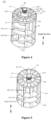
- a control valve 1 is provided according to an embodiment of the present application.
- the control valve 1 includes a valve body 10, a valve core 20, and a first sealing member 41.
- the valve body 10 includes a side wall part 11, and the control valve 1 has a valve cavity 101.
- the side wall part 11 forms a peripheral wall of the valve cavity 101 or at least part of the peripheral wall.
- the first sealing member 41 is arranged between the valve core 20 and the side wall part 11 along a radial direction of the valve core 20, and the valve core 20 can be driven to rotate.
- the control valve 1 may further include a driving device 50 and a sealing ring 43.
- the driving device 50 includes a driving member, the driving member may be a motor or a combination of a motor and a reduction gear set, and the valve core 20 can be driven to rotate by the driving member in the driving device 50.
- the valve body 10 further includes a bottom cover 12 and a top wall part 13.
- the bottom cover 12 and the valve cavity 101 are located between the top wall part 13 and the side wall part 11, and the top wall part 13 and the side wall part 11 are integrally formed.
- the sealing ring 43 is arranged between the top wall part 13 and the valve core 20, and at least part of the side wall part 11 is arranged between the bottom cover 12 and the top wall part 13.
- the bottom cover 12 and the side wall part 11 may be fixedly connected and arranged in a sealed manner through a welding process to prevent fluid leakage.
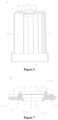
- the control valve 1 may include at least five channels 30, one end of each of the at least five channels 30 penetrates the side wall part 11 and communicates with the valve cavity 101, and the other end of each of the at least five channels 30 forms a valve port 102 of the control valve 1, and fluid can enter or leave the control valve 1 from the valve port 102.
- the valve body 10 further includes an mounting part 14, the mounting part 14 is fixedly connected to the side wall part 11 and located on a side, facing away from the valve cavity 101, of the side wall part 11.
- the mounting part 14 and the side wall part 11 may be integrally formed, the mounting part 14 has a mounting surface 141, and the valve port 102 of the control valve 1 penetrates through the mounting surface 141, so that all the valve ports 102 of the control valve 1 are formed on the mounting surface 141 and the orientations of the valve ports 102 are same, which can relatively simplify assembly steps of the control valve 1 and other components, reduce leakage points of connecting portions, and improve the reliability of sealing.
- the first sealing member 41 includes through holes 411 that penetrate through the first sealing member 41, the through holes 411 correspond to and communicate with at least part of the channels 30 of the control valve 1.
- the first sealing member 41 is deformed by the pressure from the valve core 20 and the side wall part 11, thereby realizing the sealing of the control valve 1 by the first sealing member 41.
- the channels of the control valve 1 may also be arranged along a circumferential direction of the side wall part 11, and the valve ports 102 may also be arranged along the circumferential direction of the side wall part 11, which is not limited in the present application.
- a cross section of the first sealing member 41 is of an arc-shaped structure.
- the control valve 1 may further include a second sealing member 42, the second sealing member 42 and the first sealing member 41 are respectively arranged on both sides of the valve core 20 in the radial direction of the valve core 20, so that the second sealing member 42 and the first sealing member 41 apply forces to the valve core 20, thereby maintaining the coaxiality of the valve core 20 and the side wall part 11, and improving the rotation stability of the valve core 20.
- the valve core 20 has multiple outer communication cavities 25.
- Each outer communication cavity 25 is a groove structure formed by recessing a side surface of the valve core 20 toward an interior of the valve core 20.
- corresponding two valve ports 102 can be opened and/or closed through at least part of the outer communication cavities 25.
- the valve core 20 may further include an inner communication cavity 26, multiple outer communication cavities 25 are distributed on an outer peripheral side of the inner communication cavity 26.
- the inner communication cavity 26 communicates with part of the outer communication cavities 25, so that during the rotation of the valve core 20, the corresponding two valve ports 102 can be opened and/or closed through the outer communication cavities 25 and the inner communication cavity 26, so as to realize the control of the fluid by the control valve 1.
- valve core 20 includes a top plate 201, a bottom plate 202, a first partition 23, a second partition 24, a first block 203, and a valve-core shaft assembly SA.
- the first partition 23 has a communication hole, and the inner communication cavity 26 communicates with part of the outer communication cavities 25 through the communication hole.
- Each of the outer communication cavities 25 is separated into an independent space by the second partition 24, and cross-sectional areas of cavity mouths of the outer communication cavities 25 may be different, for example, the outer communication cavities 25 may include a first cavity 251 and a second cavity 252.
- a cross-sectional area of a cavity mouth of the first cavity 251 is greater than or equal to twice a cross-sectional area of a cavity mouth of the second cavity 252.
- the first cavity 251 can open and/or close the two valve ports 102 corresponding to the first cavity 251, and the inner communication cavity 26 communicates with the part of the second cavities 252 through the communication hole, so that the inner communication cavity 26 and the part of the second cavities 252 can open and/or close the two valve ports 102 corresponding to the inner communication cavity 26 and the part of the second cavities 252.
- the top plate 201 and the bottom plate 202 of the valve core 20 are arranged along a height direction of the valve core 20, and the outer communication cavities 25 are located between the top plate 201 and the bottom plate 202, and the top plate 201 and the bottom plate 202 are mounted outside an outer peripheral side of the valve-core shaft assembly SA.
- the valve-core shaft assembly SA includes a transmission connection part 222, and at least part of the transmission connection part 222 protrudes from the top plate 201 and is located on a side of the top plate 201 facing away from the bottom plate 202.
- the valve core 20 is in transmission connection with the driving device 50 through the transmission connection part 222, so that the driving device 50 can drive the valve core 20 to rotate through the transmission connection part 222.
- the first block 203 protrudes from the top plate 201 and is fixedly connected to the top plate 201 as an integral structure, or the first block 203 and the top plate 201 may be separately provided and fixedly connected.
- the driving device 50 is arranged close to the top plate 201, the first block 203 extends from the top plate 201 toward a direction away from the bottom plate 202, and the first block 203 can limit a rotation position of the valve core 20.
- the first block 203 since the first block 203 is fixedly connected to the top plate 201 close to the transmission connection part 222, the first block 203 is relatively close to the transmission connection part 222 and the driving device 50 when the first block 203 limits the rotation position of the valve core 20, a driving force arm applied to the first block 203 is relatively small, which can reduce the torsional deformation of the valve core 20 and improve the operational stability of the control valve 1.
- the valve core 20 may further include a reinforcing rib 27, and the valve-core shaft assembly SA includes a first valve-core shaft 21 and a second valve-core shaft 22 that are in transmission connection.
- the first valve-core shaft 21 is in transmission connection with the driving device 50 through the second valve-core shaft 22, and the reinforcing rib 27 is connected between the first partition 23 and the first valve-core shaft 21.
- the transmission connection of two components refers to that a transmission force can be transmitted between the two components, and the two components may be directly connected, or may be in transmission connection through a transmission mechanism such as a gear.
- the valve body 10 further includes a top wall part 13 located at an end of the side wall part 11 in the height direction of the side wall part 11 and a second block 15.
- the top wall part 13 and the side wall part 11 are integrally formed and form part of a wall of the valve cavity 101.
- the top wall part 13 has a through hole 131, the through hole 131 communicates with the valve cavity 101.
- the second block 15 is located in the valve cavity 101 and protrudes from the top wall part 13. At least part of the transmission connection part 222 of the valve-core shaft assembly SA goes through the through hole 131 to be located outside the valve body 10.
- the whole transmission connection part 222 is arranged outside the valve body 10, and the second block 15 is fixedly connected to the top wall part 13 to form an integral structure.
- the second block 15 may be integrally formed with the top wall part 13.
- the side wall part 11, the top wall part 13, and the second block 15 can be integrally formed, so that the structural strength of the valve body 10 is improved when the first block 203 abuts against the second block 15.
- the structure of the embodiments of the present application can improve the cracking of a weld seam between the side wall part 11 and the top wall part 13.
- the valve-core shaft assembly SA includes a first valve-core shaft 21 and a second valve-core shaft 22, and the strength of the second valve-core shaft 22 is greater than the strength of the first valve-core shaft 21.
- the first valve-core shaft 21 includes a first connection part 211, and the first connection part 211 is located at an end of the first valve-core shaft 21 and at least part of the first connection part 211 is arranged in the valve cavity 101.
- the second valve-core shaft 22 includes a transmission connection part 222 and a second connection part 221, the transmission connection part 222 of the valve-core shaft assembly SA is provided in the second valve-core shaft 22, and the transmission connection part 222 is located at an end of the second valve-core shaft 22.
- the second valve-core shaft 22 further includes a second connection part 221, the second connection part 221 and the transmission connection part 222 are arranged along a height direction of the second valve-core shaft 22, at least part of the second connection part 221 is arranged in the valve cavity 101, and at least part of the transmission connection part 222 is arranged outside the valve cavity 101 and protrudes from the top wall part 13.
- An inner surface of one of the second connection part 221 and the first connection part 211 has teeth
- an outer surface of the other of the second connection part 221 and the first connection part 211 has teeth
- the teeth of the second connection part 221 meshes with the teeth of the first connection part 211.
- the valve core 20 may include a first spiral reinforcing rib 213, a second spiral reinforcing rib 214, and a third spiral reinforcing rib 224.
- the first spiral reinforcing rib 213 is located between an outer surface of the first valve-core shaft 21 and an inner surface of the first partition 23, the second spiral reinforcing rib 214 is located in a cavity enclosed by an inner surface of the first valve-core shaft 21, and the third spiral reinforcing rib 224 may be located in a cavity enclosed by an inner surface of the second valve-core shaft 22.
- first spiral reinforcing rib 213, the second spiral reinforcing rib 214, and the third spiral reinforcing rib 224 are spiral extension structures
- first spiral reinforcing rib 213, the second spiral reinforcing rib 214, the first valve-core shaft 21, the first partition 23, and the second partition 24 may be integrally formed by injection molding
- third spiral reinforcing rib 224 may be integrally formed with the second valve-core shaft 22.
- the inner surface of the second connection part 221 of the second valve-core shaft 22 is of a toothed structure
- the outer surface of the first connection part 211 of the first valve-core shaft 21 is of a toothed structure.
- the transmission connection between the first valve-core shaft 251 and the second valve-core shaft 22 is realized through the meshing of the toothed structures, so that the first valve-core shaft 251 and the second valve-core shaft 252 can rotate synchronously.
- a constituent material of the first valve-core shaft 21 may be a combination of polyamide 66 (PA66) and glass fiber (GF), or a combination of polyphthalamide (PPA) and glass fiber (GF), or polyphenylene sulfide (PPS), a constituent material of the second valve-core shaft 22 may be one or a combination of metal and polyphenylene sulfide (PPS).
- the control valve 1 may not be provided with the second valve-core shaft 22, and the first valve-core shaft 21 may be in transmission connection with the driving device, so that the driving device drives the valve core to rotate.
- an output torque of the control valve 1 is 3.5N.m to 4.5N.m
- an input torque of the valve-core shaft assembly SA is 3.5N.m to 4.5N.m
- a length of a meshing part of the teeth of the second connection part 221 and the teeth of the first connection part 211 is 10mm to 15mm.
- a linear expansion coefficient of the second valve-core shaft 22 is less than or equal to a linear expansion coefficient of the first valve-core shaft 21, so that the size change of the second valve-core shaft 22 is relatively small when the second valve core shaft 22 is at ambient temperature, which can make the control valve 1 suitable for environments with various temperatures and improve the applicability of the control valve 1.
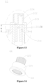
- the second valve-core shaft 22 includes a step part 223, the step part 223 is fixedly connected with the second connection part 221 to form an integrated structure, as shown in Figure 10 , or the step part 223 and the second connection part 221 may be separately arranged but fixedly connected.
- the step part 223 has a step surface 2231, the step surface 2231 is disposed opposite to the top wall part 13 and there is a gap between the step surface 2231 and the top wall part 13, and the step surface 2231 is located in the valve cavity 101.
- the control valve 1 further includes the sealing ring 43, the sealing ring 43 is coaxial with a wall of the through hole 131 of the top wall part 13.
- the sealing ring 43 is mounted on an outer peripheral side of the second valve-core shaft 22 and is arranged in the gap between the step surface 2231 of the second valve-core shaft 22 and the inner surface of the top wall part 13.
- the size change of the second valve-core shaft 22 is relatively small when the second valve-core shaft 22 is at the ambient temperature, thereby reducing the deformation of the sealing ring 43 and improving the sealing performance of the control valve 1.
- the valve body 10 further includes a guide part 16, and the guide part 16 extends from the top wall part 13 to the valve cavity 101.
- the guide part 16 has a guide channel 161 that penetrates through the guide part 16, and the guide channel 161 is coaxial with the wall of the through hole 131 of the top wall part 13 and communicates with the through hole 131 of the top wall part 13.
- the sealing ring 43 is arranged inside the guide channel 161.
- the bore diameter of the inner wall surface of the guide channel 161 decreases gradually, so that when the sealing ring 43 is assembled into the valve body 10, the inner wall surface of the guide channel 161 plays a guiding role in the assembly of the sealing ring 43, which facilitates the installation of the sealing ring 43 and improves the accuracy of the installation position of the sealing ring 43.
- the control valve 1 further includes the driving device 50
- the driving device 50 is located on a side, facing away from the valve cavity 101, of the top wall part 13.
- the driving device 50 includes a driving member, and the driving member is in transmission connection with the transmission connection part 222.
- the first block 203 and the second block 15 are both close to the driving device 50, so that when the valve core 20 rotates until the first block 203 abuts against the second block 15, the driving force arm applied to the valve core 50 is relatively small, which reduces the distortion deformation of the valve core 20.
- the valve body 10 further includes a bottom cover 12, the bottom cover 12 is located on a side, facing away from the top wall part 13, of the side wall part 11, the bottom cover 12 and the side wall part 11 are fixedly arranged and the bottom cover 12 is sealingly connected to the side wall part 11.
- the bottom cover 12 includes a bottom wall part 121 and a limit part 122, and the limit part 12 protrudes from the bottom wall part 121 and is arranged in the valve cavity 101.
- the valve-core shaft assembly SA further includes a support part 212, the support part 212 is located at an end, facing away from the top plate 201, of the first valve-core shaft 21, and the support part 212 is located on a side of the bottom plate 202 of the valve core 20.
- the support part 212 is limitedly connected to the limit part 122.
- the limit part 122 is of a groove structure, and the support part 212 is inserted into the groove structure.
- the first block 203 in the valve core 20 and the second block 15 in the valve body 10
- the first block 203 abuts against the second block 15 and restricts the valve core 20 from continuing to move towards the second block 15 when the valve core 20 rotates to the predetermined position, so that the position reference is formed between the valve core 20 and the valve body 10, thereby making the rotation position of the valve core 20 more accurate, so as to improve the control accuracy of the control valve 1.
- the valve core 20 includes the transmission connection part 222, and the transmission connection part 222 can be in transmission connection with the driving device 50 to drive the valve core 20 to rotate.
- the first block 203 is fixedly connected to the top plate 201 close to the transmission connection part 222, and the second block 15 is fixedly connected to the top wall part 13 close to the transmission connection part 222, so that when the first block 203 abuts against the second block 15, the first block 203 is relatively close to the transmission connection part 222 and the driving device 50, and the driving force arm applied on the is first block 203 is relatively small, which can reduce the torsional deformation of valve core 20 and improve the operational stability of the control valve 1.
- a method for manufacturing a control valve is further provided according to the embodiments of the present application.
- the method for manufacturing a control valve includes the following steps S110 to S 160.
- step S110 a valve core 20, a valve body 10, a sealing ring 43, and a bottom cover 12 are provided.
- the valve core 20 includes a valve-core shaft assembly SA, and the valve-core shaft assembly SA includes a first valve-core shaft 21 and a second valve-core shaft 22.
- the first valve-core shaft 21 includes a first connection part 211
- the second valve-core shaft 22 includes a second connection part 221, a step part 223 and a transmission connection part 222.
- the transmission connection part 222 and the second connection part 221 are arranged along a height direction of the second valve-core shaft 22, and the step part 223 is located on an outer peripheral side of the second connection part 221, and the step part 223 and the second connection part 221 are fixedly connected to form an integrated structure, as shown in Figure 10 , or, the step part 223 and the second connection part 221 may be arranged separately but fixedly connected.
- the step part 223 has a step surface 2231, and the step surface 2231 may be perpendicular to the height direction of the second valve core axis 22.
- the valve body 10 includes a side wall part 11 and a top wall part 13, and the control valve 1 has a valve cavity 101.
- the top wall part 13 and the side wall part 11 are integrally formed and define the valve cavity 101.
- the top wall part 13 is located at one end of the side wall part 11, and the other end of the side wall part 11 has an opening 111 communicating with the valve cavity 101.
- the top wall part 13 has a through hole 131 that penetrates through the top wall part 13, and the through hole 131 communicates with the valve cavity 101.
- the valve core 20 includes a top plate 201, a bottom plate 202, a first block 203, and the valve-core shaft assembly SA.
- the top plate 201 and the bottom plate 202 are arranged along a height direction of the valve core 20.
- the valve-core shaft assembly SA includes the transmission connection part 222, and at least part of the transmission connection part 222 is located on a side, facing away from the bottom plate 202, of the top plate 201.
- the valve body 10 further includes the top wall part 13 and the second block 15, and the top wall part 13 is disposed close to an end of the side wall part 11.
- the structures of the valve body 10 and the valve core 20 in the embodiments of the present application is the same as the structures of the valve body 10 and valve core 20 provided in any of the above embodiments, which are not repeated here.
- step S120 a valve core assembly is formed.
- step S120 includes assembling the first valve-core shaft 21, the second valve-core shaft 22, and the sealing ring 43 to allow the first connection part 211 to be in transmission connection with the second connection part 221.
- the sealing ring 43 is mounted on an outer peripheral side of the second valve-core shaft 22 and contacts the step surface 2231 or there is a gap between the sealing ring 43 and the step surface 2231.
- an inner diameter of the sealing ring 43 is smaller than an outer diameter of the second valve-core shaft 22, so that the sealing ring 43 is relatively stably limited on the second valve-core shaft 22.
- step S130 the valve core assembly is mounted into the valve cavity 101 from the opening 111, and at least part of the transmission connection part 222 is caused to go through the through hole 131 to be located outside the valve body 10.
- valve core 20 is mounted into the valve cavity 101 from the opening 111, and at least part of the transmission connection part 222 is caused to go through the through hole 131 to be located outside the valve body 10, so that when the valve core 20 rotates to a predetermined position, the first block 203 abuts against the second block 15 and restricts the valve core 20 from continuing to rotate towards the second block 15.
- step S140 the bottom cover 12 is fixedly connected to an end, away from the top wall part 13, of the side wall part 11, and the bottom cover 12 and the end, away from the top wall part 13, of the side wall part 11 are arranged in a sealed manner.
- the first sealing member 41 and the second sealing member 42 may be first mounted in the valve cavity 101 to ensure that the control valve 1 has a good sealing performance.
- the control valve manufactured by the above method for manufacturing a control valve has same beneficial effects as the control valve described above, and the deformation of the sealing ring 43 can be improved, which are not repeated here.
- the bottom cover 12 includes a bottom wall part 121 and a limit part 122, the limit part 122 protrudes from the bottom wall part 121, the first valve-core shaft 21 has a support part 212, the support part 212 is located at one end of the first valve-core shaft 21, and the first connection part 211 is located at the other end of the first valve-core shaft 21.
- Step S140 that the bottom cover 12 is fixedly connected to an end, away from the top wall part 13, of the side wall part 11, and the bottom cover 12 and the end, away from the top wall part 13, of the side wall part 11 are arranged in a sealed manner includes: limitedly connecting the support part 212 to the limit part 122; and fixedly connecting the bottom cover to the side wall part and arranging the bottom cover and the side wall part in a sealed manner through a welding process.
- a whole circle may be welded around the bottom cover 12 and the side wall part 11 through a laser welding process, so that the bottom cover 12 and the side wall part 11 are fixedly connected and arranged in a sealed manner.
- an inner surface of one of the second connection part 221 and the first connection part 211 has teeth
- an outer surface of the other of the second connection part 221 and the first connection part 211 has teeth
- step S120 that the valve core assembly is formed includes: forming the second valve-core shaft assembly including mounting the sealing ring 43 on the outer peripheral side of the second valve-core shaft 22 and making the sealing ring 43 contact or spaced apart from the step surface 2231, where an inner diameter of the sealing ring 43 is smaller than an outer diameter of the step surface 2231; meshing the teeth of the second connection part 221 and the teeth of the first connection part 211 and making a length of a meshing part10mm to15mm.
Landscapes
- Engineering & Computer Science (AREA)
- General Engineering & Computer Science (AREA)
- Mechanical Engineering (AREA)
- Electrically Driven Valve-Operating Means (AREA)
- Sliding Valves (AREA)
- Multiple-Way Valves (AREA)
Applications Claiming Priority (2)
| Application Number | Priority Date | Filing Date | Title |
|---|---|---|---|
| CN202110411384.6A CN115218003B (zh) | 2021-04-16 | 2021-04-16 | 控制阀及其制造方法 |
| PCT/CN2022/087033 WO2022218405A1 (zh) | 2021-04-16 | 2022-04-15 | 控制阀及其制造方法 |
Publications (2)
| Publication Number | Publication Date |
|---|---|
| EP4325100A1 true EP4325100A1 (de) | 2024-02-21 |
| EP4325100A4 EP4325100A4 (de) | 2025-06-25 |
Family
ID=83605735
Family Applications (1)
| Application Number | Title | Priority Date | Filing Date |
|---|---|---|---|
| EP22787627.3A Pending EP4325100A4 (de) | 2021-04-16 | 2022-04-15 | Steuerventil und herstellungsverfahren dafür |
Country Status (5)
| Country | Link |
|---|---|
| US (1) | US12571486B2 (de) |
| EP (1) | EP4325100A4 (de) |
| JP (1) | JP7813813B2 (de) |
| CN (1) | CN115218003B (de) |
| WO (1) | WO2022218405A1 (de) |
Families Citing this family (3)
| Publication number | Priority date | Publication date | Assignee | Title |
|---|---|---|---|---|
| CN115218005A (zh) * | 2021-04-16 | 2022-10-21 | 浙江三花汽车零部件有限公司 | 控制阀 |
| CN115654180B (zh) * | 2022-11-07 | 2025-09-12 | 亿创氢能源科技(张家港)有限公司 | 一种多通阀体 |
| CN115654177B (zh) * | 2022-12-26 | 2023-03-14 | 四川芯智热控技术有限公司 | 一种多通阀 |
Family Cites Families (29)
| Publication number | Priority date | Publication date | Assignee | Title |
|---|---|---|---|---|
| WO1995022023A1 (en) | 1994-02-10 | 1995-08-17 | Nippondenso Co., Ltd. | Flow rate control rotary valve |
| US5816290A (en) | 1996-03-13 | 1998-10-06 | Fleck Controls, Inc. | Rotary control valve for a water conditioning system |
| JP4412566B2 (ja) | 1999-09-08 | 2010-02-10 | コスモ工機株式会社 | 切換弁装置 |
| JP2006009830A (ja) | 2004-06-22 | 2006-01-12 | Hitachi Valve Ltd | 樹脂製ボール弁 |
| CN100549478C (zh) * | 2007-09-18 | 2009-10-14 | 虞仕君 | 一种浮动圆锥旋塞阀 |
| JP4706981B2 (ja) * | 2008-06-13 | 2011-06-22 | Toto株式会社 | シリンダ弁 |
| CN201246487Y (zh) * | 2008-08-19 | 2009-05-27 | 浙江盾安禾田金属有限公司 | 一种球阀开关结构 |
| DE102009035349B4 (de) | 2009-07-30 | 2018-06-28 | BorgWarner Esslingen GmbH | Steuervorrichtung für den Kühlmittelfluss im Kühlkreislauf einer Brennkraftmaschine |
| JP2013221593A (ja) | 2012-04-18 | 2013-10-28 | Asoh Kk | バルブの電動式制御装置 |
| US9500299B2 (en) | 2013-07-25 | 2016-11-22 | Schaeffler Technologies AG & Co. KG | Thermal management valve module with isolated flow chambers |
| CN103759032B (zh) * | 2014-01-08 | 2017-06-13 | 上海鸿研物流技术有限公司 | 阀门 |
| JP6432433B2 (ja) | 2014-07-07 | 2018-12-05 | 株式会社デンソー | バルブ装置 |
| CN104896147A (zh) * | 2015-04-23 | 2015-09-09 | 武汉理工大学 | 一种三通换向阀 |
| CN205244483U (zh) * | 2015-12-01 | 2016-05-18 | 广东万家乐燃气具有限公司 | 一种燃气热水器用两位四通阀 |
| CN116181472B (zh) | 2016-09-27 | 2026-02-10 | 株式会社电装 | 阀装置 |
| CN108730553B (zh) * | 2017-04-17 | 2020-04-28 | 浙江三花汽车零部件有限公司 | 一种电动阀 |
| CN107202173B (zh) | 2017-06-09 | 2019-01-01 | 立信阀门集团有限公司 | 水量调节阀 |
| CN109237054B (zh) * | 2017-07-11 | 2020-06-23 | 浙江三花制冷集团有限公司 | 旋转式切换阀 |
| CN109424766B (zh) * | 2017-08-28 | 2022-07-12 | 浙江三花制冷集团有限公司 | 一种旋转式换向阀 |
| JP6577066B2 (ja) | 2018-01-16 | 2019-09-18 | 株式会社不二工機 | 流路切換弁 |
| JP6684837B2 (ja) | 2018-01-29 | 2020-04-22 | 株式会社不二工機 | 電動弁 |
| JP7192467B2 (ja) | 2018-05-31 | 2022-12-20 | 株式会社デンソー | バルブ装置 |
| CN110566693A (zh) * | 2018-06-06 | 2019-12-13 | 盾安环境技术有限公司 | 车用四通阀 |
| CN108708992A (zh) | 2018-08-07 | 2018-10-26 | 台州力和环保科技有限公司 | 一种阀芯 |
| CN211501747U (zh) * | 2019-09-19 | 2020-09-15 | 盾安环境技术有限公司 | 三通阀 |
| US11313477B2 (en) * | 2019-09-20 | 2022-04-26 | Zibo Votaisi Petrochemical Equipment Co., Ltd | Ball valve with forced-sealing operation |
| JP7060657B2 (ja) | 2020-08-21 | 2022-04-26 | 日立Astemo株式会社 | 弁装置および自動車用熱媒体システム |
| CN114517843A (zh) * | 2020-11-20 | 2022-05-20 | 浙江三花汽车零部件有限公司 | 控制阀和控制阀系统 |
| CN115218005A (zh) * | 2021-04-16 | 2022-10-21 | 浙江三花汽车零部件有限公司 | 控制阀 |
-
2021
- 2021-04-16 CN CN202110411384.6A patent/CN115218003B/zh active Active
-
2022
- 2022-04-15 EP EP22787627.3A patent/EP4325100A4/de active Pending
- 2022-04-15 WO PCT/CN2022/087033 patent/WO2022218405A1/zh not_active Ceased
- 2022-04-15 JP JP2023563235A patent/JP7813813B2/ja active Active
- 2022-04-15 US US18/555,549 patent/US12571486B2/en active Active
Also Published As
| Publication number | Publication date |
|---|---|
| CN115218003B (zh) | 2026-04-17 |
| US12571486B2 (en) | 2026-03-10 |
| JP2024513613A (ja) | 2024-03-26 |
| WO2022218405A1 (zh) | 2022-10-20 |
| JP7813813B2 (ja) | 2026-02-13 |
| CN115218003A (zh) | 2022-10-21 |
| US20240200685A1 (en) | 2024-06-20 |
| EP4325100A4 (de) | 2025-06-25 |
Similar Documents
| Publication | Publication Date | Title |
|---|---|---|
| EP4325100A1 (de) | Steuerventil und herstellungsverfahren dafür | |
| US11384852B2 (en) | Ball valve | |
| EP4325104A1 (de) | Steuerventil und dichtungselement | |
| CN113785148B (zh) | 流量控制阀 | |
| US20240035580A1 (en) | Control valve | |
| KR20010020173A (ko) | 유체 기계 | |
| CN111188912A (zh) | 一种电磁阀 | |
| US7475704B2 (en) | Valve drive device | |
| US11378197B2 (en) | Valve | |
| CN118793810A (zh) | 一种集成组件以及集成组件的装配方法 | |
| CN113944796B (zh) | 电动阀 | |
| CN116557565A (zh) | 电动阀 | |
| WO1997019268A1 (fr) | Pompe a palettes | |
| GB2158148A (en) | Door closer | |
| CN223984819U (zh) | 密封结构及插板阀 | |
| CN111350843B (zh) | 球阀 | |
| WO2022012260A1 (zh) | 电动阀 | |
| CN114165621B (zh) | 一种活塞式换向阀 | |
| WO2023143060A1 (zh) | 电动阀及其制造方法 | |
| CN114198515B (zh) | 一种内置式气动直通阀 | |
| JP2019528413A (ja) | スリーブアセンブリ、それを有する制御弁、及び空調システム | |
| JP2000345867A (ja) | 電動式スロットルバルブ装置 | |
| CN115523325B (zh) | 控制阀 | |
| CN118793825A (zh) | 电动阀 | |
| CN117823656A (zh) | 阀模块、电动阀及其制造方法 |
Legal Events
| Date | Code | Title | Description |
|---|---|---|---|
| STAA | Information on the status of an ep patent application or granted ep patent |
Free format text: STATUS: THE INTERNATIONAL PUBLICATION HAS BEEN MADE |
|
| PUAI | Public reference made under article 153(3) epc to a published international application that has entered the european phase |
Free format text: ORIGINAL CODE: 0009012 |
|
| STAA | Information on the status of an ep patent application or granted ep patent |
Free format text: STATUS: REQUEST FOR EXAMINATION WAS MADE |
|
| 17P | Request for examination filed |
Effective date: 20231019 |
|
| AK | Designated contracting states |
Kind code of ref document: A1 Designated state(s): AL AT BE BG CH CY CZ DE DK EE ES FI FR GB GR HR HU IE IS IT LI LT LU LV MC MK MT NL NO PL PT RO RS SE SI SK SM TR |
|
| DAV | Request for validation of the european patent (deleted) | ||
| DAX | Request for extension of the european patent (deleted) | ||
| RIC1 | Information provided on ipc code assigned before grant |
Ipc: F16K 31/53 20060101ALI20250228BHEP Ipc: F16K 31/04 20060101ALI20250228BHEP Ipc: F16K 5/04 20060101ALI20250228BHEP Ipc: F16K 27/06 20060101ALI20250228BHEP Ipc: F16K 11/085 20060101AFI20250228BHEP |
|
| A4 | Supplementary search report drawn up and despatched |
Effective date: 20250527 |
|
| RIC1 | Information provided on ipc code assigned before grant |
Ipc: F16K 31/53 20060101ALI20250521BHEP Ipc: F16K 31/04 20060101ALI20250521BHEP Ipc: F16K 5/04 20060101ALI20250521BHEP Ipc: F16K 27/06 20060101ALI20250521BHEP Ipc: F16K 11/085 20060101AFI20250521BHEP |
|
| STAA | Information on the status of an ep patent application or granted ep patent |
Free format text: STATUS: THE APPLICATION IS DEEMED TO BE WITHDRAWN |