EP4325103A1 - Soupape rotative - Google Patents
Soupape rotative Download PDFInfo
- Publication number
- EP4325103A1 EP4325103A1 EP22191248.8A EP22191248A EP4325103A1 EP 4325103 A1 EP4325103 A1 EP 4325103A1 EP 22191248 A EP22191248 A EP 22191248A EP 4325103 A1 EP4325103 A1 EP 4325103A1
- Authority
- EP
- European Patent Office
- Prior art keywords
- valve core
- valve
- core element
- rotation
- clutch
- Prior art date
- Legal status (The legal status is an assumption and is not a legal conclusion. Google has not performed a legal analysis and makes no representation as to the accuracy of the status listed.)
- Granted
Links
Images

Classifications
-
- F—MECHANICAL ENGINEERING; LIGHTING; HEATING; WEAPONS; BLASTING
- F16—ENGINEERING ELEMENTS AND UNITS; GENERAL MEASURES FOR PRODUCING AND MAINTAINING EFFECTIVE FUNCTIONING OF MACHINES OR INSTALLATIONS; THERMAL INSULATION IN GENERAL
- F16K—VALVES; TAPS; COCKS; ACTUATING-FLOATS; DEVICES FOR VENTING OR AERATING
- F16K11/00—Multiple-way valves, e.g. mixing valves; Pipe fittings incorporating such valves
- F16K11/02—Multiple-way valves, e.g. mixing valves; Pipe fittings incorporating such valves with all movable sealing faces moving as one unit
- F16K11/08—Multiple-way valves, e.g. mixing valves; Pipe fittings incorporating such valves with all movable sealing faces moving as one unit comprising only taps or cocks
- F16K11/085—Multiple-way valves, e.g. mixing valves; Pipe fittings incorporating such valves with all movable sealing faces moving as one unit comprising only taps or cocks with cylindrical plug
- F16K11/0853—Multiple-way valves, e.g. mixing valves; Pipe fittings incorporating such valves with all movable sealing faces moving as one unit comprising only taps or cocks with cylindrical plug having all the connecting conduits situated in a single plane perpendicular to the axis of the plug
-
- F—MECHANICAL ENGINEERING; LIGHTING; HEATING; WEAPONS; BLASTING
- F16—ENGINEERING ELEMENTS AND UNITS; GENERAL MEASURES FOR PRODUCING AND MAINTAINING EFFECTIVE FUNCTIONING OF MACHINES OR INSTALLATIONS; THERMAL INSULATION IN GENERAL
- F16K—VALVES; TAPS; COCKS; ACTUATING-FLOATS; DEVICES FOR VENTING OR AERATING
- F16K11/00—Multiple-way valves, e.g. mixing valves; Pipe fittings incorporating such valves
- F16K11/10—Multiple-way valves, e.g. mixing valves; Pipe fittings incorporating such valves with two or more closure members not moving as a unit
- F16K11/14—Multiple-way valves, e.g. mixing valves; Pipe fittings incorporating such valves with two or more closure members not moving as a unit operated by one actuating member, e.g. a handle
- F16K11/16—Multiple-way valves, e.g. mixing valves; Pipe fittings incorporating such valves with two or more closure members not moving as a unit operated by one actuating member, e.g. a handle which only slides, or only turns, or only swings in one plane
- F16K11/163—Multiple-way valves, e.g. mixing valves; Pipe fittings incorporating such valves with two or more closure members not moving as a unit operated by one actuating member, e.g. a handle which only slides, or only turns, or only swings in one plane only turns
- F16K11/165—Multiple-way valves, e.g. mixing valves; Pipe fittings incorporating such valves with two or more closure members not moving as a unit operated by one actuating member, e.g. a handle which only slides, or only turns, or only swings in one plane only turns with the rotating spindles parallel to the closure members
-
- F—MECHANICAL ENGINEERING; LIGHTING; HEATING; WEAPONS; BLASTING
- F01—MACHINES OR ENGINES IN GENERAL; ENGINE PLANTS IN GENERAL; STEAM ENGINES
- F01P—COOLING OF MACHINES OR ENGINES IN GENERAL; COOLING OF INTERNAL-COMBUSTION ENGINES
- F01P7/00—Controlling of coolant flow
- F01P7/14—Controlling of coolant flow the coolant being liquid
- F01P7/16—Controlling of coolant flow the coolant being liquid by thermostatic control
- F01P7/165—Controlling of coolant flow the coolant being liquid by thermostatic control characterised by systems with two or more loops
-
- F—MECHANICAL ENGINEERING; LIGHTING; HEATING; WEAPONS; BLASTING
- F16—ENGINEERING ELEMENTS AND UNITS; GENERAL MEASURES FOR PRODUCING AND MAINTAINING EFFECTIVE FUNCTIONING OF MACHINES OR INSTALLATIONS; THERMAL INSULATION IN GENERAL
- F16K—VALVES; TAPS; COCKS; ACTUATING-FLOATS; DEVICES FOR VENTING OR AERATING
- F16K11/00—Multiple-way valves, e.g. mixing valves; Pipe fittings incorporating such valves
- F16K11/10—Multiple-way valves, e.g. mixing valves; Pipe fittings incorporating such valves with two or more closure members not moving as a unit
- F16K11/12—Multiple-way valves, e.g. mixing valves; Pipe fittings incorporating such valves with two or more closure members not moving as a unit with one plug turning in another
-
- F—MECHANICAL ENGINEERING; LIGHTING; HEATING; WEAPONS; BLASTING
- F16—ENGINEERING ELEMENTS AND UNITS; GENERAL MEASURES FOR PRODUCING AND MAINTAINING EFFECTIVE FUNCTIONING OF MACHINES OR INSTALLATIONS; THERMAL INSULATION IN GENERAL
- F16K—VALVES; TAPS; COCKS; ACTUATING-FLOATS; DEVICES FOR VENTING OR AERATING
- F16K11/00—Multiple-way valves, e.g. mixing valves; Pipe fittings incorporating such valves
- F16K11/10—Multiple-way valves, e.g. mixing valves; Pipe fittings incorporating such valves with two or more closure members not moving as a unit
- F16K11/14—Multiple-way valves, e.g. mixing valves; Pipe fittings incorporating such valves with two or more closure members not moving as a unit operated by one actuating member, e.g. a handle
- F16K11/18—Multiple-way valves, e.g. mixing valves; Pipe fittings incorporating such valves with two or more closure members not moving as a unit operated by one actuating member, e.g. a handle with separate operating movements for separate closure members
-
- F—MECHANICAL ENGINEERING; LIGHTING; HEATING; WEAPONS; BLASTING
- F16—ENGINEERING ELEMENTS AND UNITS; GENERAL MEASURES FOR PRODUCING AND MAINTAINING EFFECTIVE FUNCTIONING OF MACHINES OR INSTALLATIONS; THERMAL INSULATION IN GENERAL
- F16K—VALVES; TAPS; COCKS; ACTUATING-FLOATS; DEVICES FOR VENTING OR AERATING
- F16K31/00—Actuating devices; Operating means; Releasing devices
- F16K31/02—Actuating devices; Operating means; Releasing devices electric; magnetic
- F16K31/04—Actuating devices; Operating means; Releasing devices electric; magnetic using a motor
- F16K31/041—Actuating devices; Operating means; Releasing devices electric; magnetic using a motor for rotating valves
- F16K31/043—Actuating devices; Operating means; Releasing devices electric; magnetic using a motor for rotating valves characterised by mechanical means between the motor and the valve, e.g. lost motion means reducing backlash, clutches, brakes or return means
-
- F—MECHANICAL ENGINEERING; LIGHTING; HEATING; WEAPONS; BLASTING
- F16—ENGINEERING ELEMENTS AND UNITS; GENERAL MEASURES FOR PRODUCING AND MAINTAINING EFFECTIVE FUNCTIONING OF MACHINES OR INSTALLATIONS; THERMAL INSULATION IN GENERAL
- F16K—VALVES; TAPS; COCKS; ACTUATING-FLOATS; DEVICES FOR VENTING OR AERATING
- F16K5/00—Plug valves; Taps or cocks comprising only cut-off apparatus having at least one of the sealing faces shaped as a more or less complete surface of a solid of revolution, the opening and closing movement being predominantly rotary
- F16K5/04—Plug valves; Taps or cocks comprising only cut-off apparatus having at least one of the sealing faces shaped as a more or less complete surface of a solid of revolution, the opening and closing movement being predominantly rotary with plugs having cylindrical surfaces; Packings therefor
- F16K5/0407—Plug valves; Taps or cocks comprising only cut-off apparatus having at least one of the sealing faces shaped as a more or less complete surface of a solid of revolution, the opening and closing movement being predominantly rotary with plugs having cylindrical surfaces; Packings therefor with particular plug arrangements, e.g. particular shape or built-in means
-
- B—PERFORMING OPERATIONS; TRANSPORTING
- B60—VEHICLES IN GENERAL
- B60K—ARRANGEMENT OR MOUNTING OF PROPULSION UNITS OR OF TRANSMISSIONS IN VEHICLES; ARRANGEMENT OR MOUNTING OF PLURAL DIVERSE PRIME-MOVERS IN VEHICLES; AUXILIARY DRIVES FOR VEHICLES; INSTRUMENTATION OR DASHBOARDS FOR VEHICLES; ARRANGEMENTS IN CONNECTION WITH COOLING, AIR INTAKE, GAS EXHAUST OR FUEL SUPPLY OF PROPULSION UNITS IN VEHICLES
- B60K11/00—Arrangement in connection with cooling of propulsion units
- B60K11/02—Arrangement in connection with cooling of propulsion units with liquid cooling
-
- F—MECHANICAL ENGINEERING; LIGHTING; HEATING; WEAPONS; BLASTING
- F01—MACHINES OR ENGINES IN GENERAL; ENGINE PLANTS IN GENERAL; STEAM ENGINES
- F01P—COOLING OF MACHINES OR ENGINES IN GENERAL; COOLING OF INTERNAL-COMBUSTION ENGINES
- F01P7/00—Controlling of coolant flow
- F01P7/14—Controlling of coolant flow the coolant being liquid
- F01P2007/146—Controlling of coolant flow the coolant being liquid using valves
Definitions
- the invention relates to a rotary valve, comprising a valve housing with a valve chamber, the valve chamber having a chamber wall into which at least two fluid openings are introduced, the valve chamber receiving a valve core, the valve core being provided with a channel structure which interacts with the fluid openings, wherein the valve core is rotatably mounted in the valve chamber.
- Such a rotary valve is, for example, from DE 10 2018 009 680 A1 known.
- Rotary valves of the type mentioned are often used in cooling circuits to control the coolant flow.
- a cooling fluid can flow in and out through the fluid openings made in the valve housing.
- the channel structure introduced into the valve core controls the coolant flow, whereby different cooling circuits can be controlled, the volume flow can be regulated or the flow direction can be adjusted depending on the design and number of fluid openings.
- the design as a rotary valve is advantageous because the coolant flow is adjusted by rotating the valve core, the corresponding actuator for rotating the valve core being simple and easy to control. Accordingly, rotary valves and the associated actuators can be produced cost-effectively. In addition, rotary valves require very little installation space.
- Such rotary valves are particularly advantageous with regard to use in temperature control circuits in the field of electromobility.
- Components to be tempered Electric vehicles are, in particular, electrical energy storage devices, but also the power electronics or plug connections of fast charging devices.
- An electrical energy storage device only has the best possible capacity in a very small temperature range. It is therefore necessary to heat the electrical energy storage systems of electric vehicles at low ambient temperatures and to cool them at high outside temperatures or during high load changes.
- a temperature control circuit through which a temperature control medium flows.
- the temperature control medium can either be heated in a heating device or cooled in a cooling device.
- the control of the temperature control medium flow takes place at least partially via a rotary valve. This may result in the need for complex channel structures in the valve core.
- the invention is based on the object of providing a rotary valve which can be produced cost-effectively and which enables complex control of temperature control circuits.
- the rotary valve comprises a valve housing with a valve chamber, the valve chamber having a chamber wall into which at least two fluid openings are introduced, the valve chamber receiving a valve core, the valve core being provided with a channel structure which interacts with the fluid openings, the valve core rotatably mounted in the valve chamber and can be set in rotation via a drive shaft, the valve core being designed in several parts and having at least a first valve core element and a second valve core element, the first valve core element having a first channel structure and the second valve core element having a second channel structure, wherein the first valve core element and the second valve core element are operatively connected to the drive shaft.
- the multi-part design of the valve core makes it possible to implement complex controls for temperature control circuits.
- the first valve core element and the second valve core element are provided with channel structures that can interact independently with the respective fluid openings. Accordingly, a first temperature control circuit can be implemented via the channel structure of the first valve core element and a second temperature control circuit can be implemented via the channel structure of the second valve core element.
- the first valve core element and the second valve core element are operatively connected to the drive shaft, wherein the two valve core elements can be rotatable independently of one another. This means that either only the first valve core element or only the second valve core element or both valve core elements can be rotated by rotational movement of the drive shaft. This makes it possible to implement complex controls of various temperature control circuits cost-effectively using simple means.
- the first valve core element can be operatively connected to the drive shaft via a first clutch.
- the clutch transmits the torque of the drive shaft to the first valve core element.
- the clutch can be designed in such a way that the power flow is selectively interrupted, so that when the drive shaft rotates, there is no torque transfer and, accordingly, no rotation of the valve core element.
- the second valve core element can be operatively connected to the drive shaft via a second clutch.
- a second clutch can be operatively connected to the drive shaft via a second clutch.
- the design with two clutches enables particularly flexible and complex control of different temperature control circuits.
- the design with only one clutch is cost-effective.
- the first clutch and/or the second clutch can be designed as a one-way clutch.
- a clutch designed as a freewheel transmits torque only in one direction of rotation, whereas in the opposite direction of rotation there is no torque transfer.
- a freewheel is a passive clutch and enables switching operations without the use of auxiliary energy.
- the clutches are designed as clutches and are switched, for example, via an actuator.
- the freewheel of the first clutch can transmit a torque in a first direction of rotation.
- the freewheel of the second clutch can transmit torque in a second direction of rotation, which is opposite to the first direction of rotation.
- a rotation of the drive shaft in a first direction causes only one valve core element to rotate and a rotation in the opposite direction causes the other valve core element to rotate.
- Locking elements can be provided. These can be designed in such a way that they cause an increased torque for the rotational movement of the valve core elements at predetermined rotational positions. This makes it possible to counteract unwanted rotational movements of the valve core elements, for example due to fluid forces, vibrations or other influences such as drag torque.
- the friction of the valve core on the chamber wall can be used to avoid unwanted rotational movements.
- the rotary valve can be equipped with one or more sensors to determine the position of the valve core elements.
- the sensors enable the angular position of the valve core elements to be recorded, which can be done, for example, via pressure, fluid flow or position measurement. If the sensors detect a loss of position, the valve core elements can be brought back into the correct position via a control system.
- the one-way clutch can be designed so that it only engages in a predetermined number of positions. This configuration enables freewheeling over a small distance also in the direction of rotation in which the torque is transmitted. This enables position monitoring without additional sensors.
- the first valve core element and the second valve core element can be operatively connected to one another via a locking means.
- the locking means can be designed in such a way that the two valve core elements can rotate independently of one another in one direction of rotation and lock with one another in a second direction of rotation, so that the two valve core elements are rotated equally in the second direction of rotation.
- one valve core element can be rotated in both directions of rotation, while the other valve core element can only rotate in one direction of rotation.
- the first valve core element and the second valve core element can be arranged one above the other when viewed in the longitudinal direction, i.e. in the direction of the axis of rotation.
- the valve core elements are arranged stacked in the valve housing and the channel structures of the two valve core elements are preferably independently connected to fluid openings. This configuration is particularly suitable for controlling several independent temperature control circuits.
- the first valve core element can influence a first temperature control circuit and the second valve core element can influence a second temperature control circuit.
- first valve core element and the second valve core element are nested radially into one another.
- a valve core element has a concentric recess in which the further valve core element is arranged.
- the channel structures of the two valve core elements can be connected to one another and particularly complex channel structures can be realized.
- valve core elements are provided, of which valve core elements are arranged one above the other when viewed in the longitudinal direction and further valve core elements are nested one inside the other.
- the valve housing can be designed in several parts. In this embodiment, it is particularly conceivable that the first valve core element is assigned to a first valve housing part and the second valve core element is assigned to a second valve housing part. In this embodiment, it is particularly easy to separate different material flows from one another, so that a first material flow flows through the first valve core element and a second material flow flows through the second valve core element.
- the multi-part design of the valve housing allows internal leaks to be avoided.
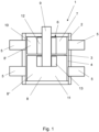
- Figure 1 shows a rotary valve 1, which forms part of a temperature control circuit of an interior device to be air-conditioned.
- the rotary valve 1 is used in electromobile applications as part of the temperature control circuit of an electric vehicle.
- the rotary valve 1 is integrated into a temperature control circuit of an electric motor drive of an electric vehicle and directs volume flows of the medium fed into the temperature control circuit to the electrical energy storage and electric motors as well as to the power electronics.
- the temperature control medium flows of the temperature control circuit can be controlled by the rotary valve 1.
- the rotary valve 1 also forms a directional control valve through which various components of the devices to be tempered can be individually and specifically supplied with tempering medium and, if necessary, can also be separated from the tempering medium flow.
- a flow of tempering medium can initially be directed exclusively to the electrical energy storage and there, depending on the ambient temperatures, the electrical energy storage can be cooled or heated.
- a coolant flow can be directed to the power electronics and also to the electric motors to cool these components.
- the modification of the coolant flow is carried out using the rotary valve 1.
- the rotary valve 1 can replace several solenoid valves, so that the temperature control circuit can be produced cost-effectively.
- Figure 1 shows a rotary valve 1 with a valve housing 2 made of plastic, in which a valve chamber 3 is arranged.
- the valve chamber 3 has a chamber wall 4 into which several fluid openings 5 are introduced.
- the valve chamber 3 has a receiving opening 6 on the front side and the valve chamber 3 accommodates a valve core 7.
- the valve core 7 is provided with a channel structure 8, which interacts with the fluid openings 5.
- the valve core 7 is rotatably mounted in the valve chamber 3 and is provided with a drive shaft 13, via which the valve core 7 can be set in rotation by an actuator.
- the valve housing 2 and the valve core 7 are made of plastic and manufactured by injection molding.
- the valve core 7 is designed in several parts and has a first valve core element 10 and a second valve core element 11.
- a first channel structure 8' is introduced into the first valve core element 10 and a second channel structure 8" is introduced into the second valve core element 11.
- the first valve core element 10 and the second valve core element 11 are operatively connected to the drive shaft 9.
- the first clutch 12 and the second clutch 13 are designed as a one-way clutch and arranged so that the freewheel of the first clutch 12 transmits a torque in a first direction of rotation and the freewheel of the second clutch 13 transmits a torque in a second direction of rotation, which is the first direction of rotation is opposite. Accordingly, rotation of the drive shaft 9 in the first direction of rotation causes the first valve core element 10 to rotate, while the drive shaft 9 does not transmit any torque to the second valve core element 11. In the second direction of rotation, no torque is transmitted from the drive shaft 9 to the first valve core element 10 and the second valve core element 11 is set in rotation by torque transfer.
- first valve core element 10 and the second valve core element 11 are arranged one above the other when viewed in the longitudinal direction of the drive shaft 9.
- the channel structures 8', 8" are each in operative connection with fluid openings 5.
- Figure 2 shows a further education of the in Figure 1 shown rotary valve 1.
- the first valve core element 10 is operatively connected to the second valve core element 11 via a locking means 14.
- the locking means 14 is designed as a one-way clutch and causes the first valve core element 10 to rotate in a first direction of rotation independently of the second valve core element 11, whereas both valve core elements 10, 11 rotate equally in a second direction of rotation by torque transfer via the locking means 14.
- the first valve core element 10 is connected to the drive shaft 9 via the first clutch 12 and the second valve core element 11 via the second clutch 13.
- a rotation of the drive shaft 9 in a first direction of rotation causes only one valve core element 10 to rotate, whereas in the second direction of rotation both valve core elements 10, 11 rotate equally due to the locking means 14 being blocked.
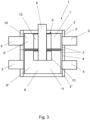
- Figure 3 shows a further education of the in Figure 1 shown rotary valve 1.
- the valve housing 2 is designed in several parts and has a first valve housing element 2 'and a second valve housing element 2".
- the first valve core element 10 is arranged in the first valve housing element 2' and the second valve core element 11 in the second valve housing element 2".
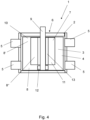
- Figure 4 shows a rotary valve 1 with a valve housing 2 made of plastic, in which a valve chamber 3 is arranged.
- the valve chamber 3 has a chamber wall 4 into which several fluid openings 5 are introduced.
- the valve chamber 3 has a receiving opening 6 on the front side and the valve chamber 3 accommodates a valve core 7.
- the valve core 7 is provided with a channel structure 8, which interacts with the fluid openings 5.
- the valve core 7 is rotatably mounted in the valve chamber 3 and is provided with a drive shaft 13, via which the valve core 7 can be set in rotation by an actuator.
- the valve core 7 is designed in several parts and has a first valve core element 10 and a second valve core element 11.
- a first channel structure 8' is introduced into the first valve core element 10
- a second channel structure 8" is introduced into the second valve core element 11.
- the first valve core element 10 and the second valve core element 11 are operatively connected to the drive shaft 9.
- the first clutch 12 and the second clutch 13 are designed as a one-way clutch and arranged so that the freewheel of the first clutch 12 blocks in a first direction of rotation and the freewheel of the second clutch 13 locks in a second direction of rotation that is opposite to the first direction of rotation.
- rotation of the drive shaft in the first direction of rotation causes the first valve core element 10 to rotate, while the drive shaft 9 does not transmit any torque to the second valve core element 11 In the second direction of rotation, no torque is transmitted from the drive shaft 9 to the first valve core element 10 and the second valve core element 11 is set in rotation by torque transfer.
- first valve core element 10 and the second valve core element 11 are nested one inside the other.
- a concentric recess is introduced into the first valve core element 10, in which the second valve core element 11 is arranged.
- the two channel structures 8', 8" are operatively connected to one another.
Landscapes
- Engineering & Computer Science (AREA)
- General Engineering & Computer Science (AREA)
- Mechanical Engineering (AREA)
- Chemical & Material Sciences (AREA)
- Combustion & Propulsion (AREA)
- Multiple-Way Valves (AREA)
- Taps Or Cocks (AREA)
Priority Applications (6)
| Application Number | Priority Date | Filing Date | Title |
|---|---|---|---|
| EP22191248.8A EP4325103B1 (fr) | 2022-08-19 | 2022-08-19 | Soupape rotative |
| PCT/EP2023/072054 WO2024037948A1 (fr) | 2022-08-19 | 2023-08-09 | Soupape rotative |
| JP2025504833A JP2025524212A (ja) | 2022-08-19 | 2023-08-09 | 回転弁 |
| KR1020257003409A KR20250026870A (ko) | 2022-08-19 | 2023-08-09 | 로터리 밸브 |
| CN202380060629.2A CN119731457A (zh) | 2022-08-19 | 2023-08-09 | 旋转阀 |
| US19/104,999 US20250283543A1 (en) | 2022-08-19 | 2023-08-09 | Rotary valve |
Applications Claiming Priority (1)
| Application Number | Priority Date | Filing Date | Title |
|---|---|---|---|
| EP22191248.8A EP4325103B1 (fr) | 2022-08-19 | 2022-08-19 | Soupape rotative |
Publications (2)
| Publication Number | Publication Date |
|---|---|
| EP4325103A1 true EP4325103A1 (fr) | 2024-02-21 |
| EP4325103B1 EP4325103B1 (fr) | 2025-10-08 |
Family
ID=83115480
Family Applications (1)
| Application Number | Title | Priority Date | Filing Date |
|---|---|---|---|
| EP22191248.8A Active EP4325103B1 (fr) | 2022-08-19 | 2022-08-19 | Soupape rotative |
Country Status (6)
| Country | Link |
|---|---|
| US (1) | US20250283543A1 (fr) |
| EP (1) | EP4325103B1 (fr) |
| JP (1) | JP2025524212A (fr) |
| KR (1) | KR20250026870A (fr) |
| CN (1) | CN119731457A (fr) |
| WO (1) | WO2024037948A1 (fr) |
Cited By (1)
| Publication number | Priority date | Publication date | Assignee | Title |
|---|---|---|---|---|
| FR3162730A1 (fr) * | 2024-05-31 | 2025-12-05 | Airbus Operations (S.A.S) | Système de prélèvement d’air pour un aéronef |
Families Citing this family (1)
| Publication number | Priority date | Publication date | Assignee | Title |
|---|---|---|---|---|
| CN120368077A (zh) * | 2025-06-16 | 2025-07-25 | 六盘山实验室 | 一种双流道超精密控制阀 |
Citations (3)
| Publication number | Priority date | Publication date | Assignee | Title |
|---|---|---|---|---|
| WO2017217112A1 (fr) * | 2016-06-15 | 2017-12-21 | 株式会社デンソー | Soupape de régulation de débit commutable |
| DE102018009680A1 (de) | 2018-12-13 | 2020-06-18 | Voss Automotive Gmbh | Massenstromsteuerungseinheit sowie Kühlmittelsystem mit zumindest einer solchen Massenstromsteuerungseinheit |
| DE102019005163A1 (de) * | 2019-07-25 | 2021-01-28 | Voss Automotive Gmbh | Massenstromsteuerungseinheit, Schaltventilelement für eine solche sowie Kühlmittelsystem mit zumindest einer solchen Massenstromsteuerungseinheit |
Family Cites Families (2)
| Publication number | Priority date | Publication date | Assignee | Title |
|---|---|---|---|---|
| JP3984079B2 (ja) * | 2002-03-12 | 2007-09-26 | 株式会社川本製作所 | 六方切換弁およびろ過装置 |
| DE102015210157B4 (de) * | 2014-06-04 | 2021-12-23 | Schaeffler Technologies AG & Co. KG | Mehrkammer-Drehventilmodul für Wärme-Management |
-
2022
- 2022-08-19 EP EP22191248.8A patent/EP4325103B1/fr active Active
-
2023
- 2023-08-09 CN CN202380060629.2A patent/CN119731457A/zh active Pending
- 2023-08-09 JP JP2025504833A patent/JP2025524212A/ja active Pending
- 2023-08-09 KR KR1020257003409A patent/KR20250026870A/ko active Pending
- 2023-08-09 US US19/104,999 patent/US20250283543A1/en active Pending
- 2023-08-09 WO PCT/EP2023/072054 patent/WO2024037948A1/fr not_active Ceased
Patent Citations (3)
| Publication number | Priority date | Publication date | Assignee | Title |
|---|---|---|---|---|
| WO2017217112A1 (fr) * | 2016-06-15 | 2017-12-21 | 株式会社デンソー | Soupape de régulation de débit commutable |
| DE102018009680A1 (de) | 2018-12-13 | 2020-06-18 | Voss Automotive Gmbh | Massenstromsteuerungseinheit sowie Kühlmittelsystem mit zumindest einer solchen Massenstromsteuerungseinheit |
| DE102019005163A1 (de) * | 2019-07-25 | 2021-01-28 | Voss Automotive Gmbh | Massenstromsteuerungseinheit, Schaltventilelement für eine solche sowie Kühlmittelsystem mit zumindest einer solchen Massenstromsteuerungseinheit |
Cited By (1)
| Publication number | Priority date | Publication date | Assignee | Title |
|---|---|---|---|---|
| FR3162730A1 (fr) * | 2024-05-31 | 2025-12-05 | Airbus Operations (S.A.S) | Système de prélèvement d’air pour un aéronef |
Also Published As
| Publication number | Publication date |
|---|---|
| CN119731457A (zh) | 2025-03-28 |
| JP2025524212A (ja) | 2025-07-25 |
| US20250283543A1 (en) | 2025-09-11 |
| KR20250026870A (ko) | 2025-02-25 |
| EP4325103B1 (fr) | 2025-10-08 |
| WO2024037948A1 (fr) | 2024-02-22 |
Similar Documents
| Publication | Publication Date | Title |
|---|---|---|
| EP4058703B1 (fr) | Ensemble soupape de commande pour le réglage d'au moins deux écoulements de fluide dans un système de conduites | |
| EP1482222B1 (fr) | Robinet à voies multiples pour un dispositif de refroidissement/chauffage d'un véhicule | |
| DE102013109587B4 (de) | Thermostatventil für eine Verbrennungskraftmaschine | |
| WO2024037948A1 (fr) | Soupape rotative | |
| DE102019107190A1 (de) | Ventil und Wärmesystem mit einem solchen Ventil | |
| EP2839139A1 (fr) | Dispositif de clapets de gaz d'échappement pour un moteur à combustion interne | |
| EP3376050B1 (fr) | Groupe pompe centrifuge | |
| DE102018114382A1 (de) | Antriebseinheit für einen Antriebsstrang eines elektrisch antreibbaren Kraftfahrzeugs und Antriebsanordnung | |
| EP3325859B1 (fr) | Module de répartition d'un agent de refroidissement pour un circuit de refroidissement | |
| DE102017218864B3 (de) | Fluidtechnische Ventileinrichtung sowie Verfahren zum Betreiben einer fluidtechnischen Ventileinrichtung | |
| DE102020207028A1 (de) | Pumpeneinheit | |
| EP1825739A1 (fr) | Dispositif de transmission à vitesse variable, en particulier pour un epandeur d'engrais | |
| DE102016000317A1 (de) | Mehrwegeventil für ein Heiz-und Kühlsystem eines Fahrzeugs | |
| DE102021116913A1 (de) | Ventilsteuervorrichtung für einen Kühlmittelkreislauf eines Kraftfahrzeugs | |
| DE102017212665A1 (de) | Kopplungsvorrichtung für ein Kraftfahrzeuggetriebe | |
| DE102019113274A1 (de) | Elektromechanische Vorrichtung mit einem Stellantrieb und einem Stellglied | |
| DE102015206975A1 (de) | Aktuatoreinheit für ein Getriebe eines Kraftfahrzeugs | |
| EP2659169B1 (fr) | Soupape de commande de débits volumétriques | |
| EP2659168B1 (fr) | Soupape de commande de débits volumétriques | |
| EP1959176B1 (fr) | Engrenage pour robinets à boisseau sphérique | |
| EP4253875A1 (fr) | Soupape rotative | |
| DE102024206848A1 (de) | Ventilmodul für eine Ventileinheit und zum Einstellen von Fluidströmen und Verteilereinheit | |
| CH707658A1 (de) | Drehstellantrieb. | |
| DE102010064332A1 (de) | Ventil zur Steuerung von Volumenströmen | |
| EP1641641B1 (fr) | Dispositif de ventilation, en particulier pour une installation de chauffage ou de climatisation d'un vehicule automobile |
Legal Events
| Date | Code | Title | Description |
|---|---|---|---|
| PUAI | Public reference made under article 153(3) epc to a published international application that has entered the european phase |
Free format text: ORIGINAL CODE: 0009012 |
|
| STAA | Information on the status of an ep patent application or granted ep patent |
Free format text: STATUS: THE APPLICATION HAS BEEN PUBLISHED |
|
| AK | Designated contracting states |
Kind code of ref document: A1 Designated state(s): AL AT BE BG CH CY CZ DE DK EE ES FI FR GB GR HR HU IE IS IT LI LT LU LV MC MK MT NL NO PL PT RO RS SE SI SK SM TR |
|
| STAA | Information on the status of an ep patent application or granted ep patent |
Free format text: STATUS: REQUEST FOR EXAMINATION WAS MADE |
|
| 17P | Request for examination filed |
Effective date: 20240815 |
|
| RBV | Designated contracting states (corrected) |
Designated state(s): AL AT BE BG CH CY CZ DE DK EE ES FI FR GB GR HR HU IE IS IT LI LT LU LV MC MK MT NL NO PL PT RO RS SE SI SK SM TR |
|
| STAA | Information on the status of an ep patent application or granted ep patent |
Free format text: STATUS: EXAMINATION IS IN PROGRESS |
|
| 17Q | First examination report despatched |
Effective date: 20241127 |
|
| GRAP | Despatch of communication of intention to grant a patent |
Free format text: ORIGINAL CODE: EPIDOSNIGR1 |
|
| STAA | Information on the status of an ep patent application or granted ep patent |
Free format text: STATUS: GRANT OF PATENT IS INTENDED |
|
| INTG | Intention to grant announced |
Effective date: 20250602 |
|
| GRAS | Grant fee paid |
Free format text: ORIGINAL CODE: EPIDOSNIGR3 |
|
| GRAA | (expected) grant |
Free format text: ORIGINAL CODE: 0009210 |
|
| STAA | Information on the status of an ep patent application or granted ep patent |
Free format text: STATUS: THE PATENT HAS BEEN GRANTED |
|
| AK | Designated contracting states |
Kind code of ref document: B1 Designated state(s): AL AT BE BG CH CY CZ DE DK EE ES FI FR GB GR HR HU IE IS IT LI LT LU LV MC MK MT NL NO PL PT RO RS SE SI SK SM TR |
|
| REG | Reference to a national code |
Ref country code: GB Ref legal event code: FG4D Free format text: NOT ENGLISH Ref country code: CH Ref legal event code: F10 Free format text: ST27 STATUS EVENT CODE: U-0-0-F10-F00 (AS PROVIDED BY THE NATIONAL OFFICE) Effective date: 20251008 |
|
| REG | Reference to a national code |
Ref country code: DE Ref legal event code: R096 Ref document number: 502022005692 Country of ref document: DE |
|
| REG | Reference to a national code |
Ref country code: IE Ref legal event code: FG4D Free format text: LANGUAGE OF EP DOCUMENT: GERMAN |
|
| REG | Reference to a national code |
Ref country code: NL Ref legal event code: MP Effective date: 20251008 |
|
| PG25 | Lapsed in a contracting state [announced via postgrant information from national office to epo] |
Ref country code: NL Free format text: LAPSE BECAUSE OF FAILURE TO SUBMIT A TRANSLATION OF THE DESCRIPTION OR TO PAY THE FEE WITHIN THE PRESCRIBED TIME-LIMIT Effective date: 20251008 |
|
| PG25 | Lapsed in a contracting state [announced via postgrant information from national office to epo] |
Ref country code: ES Free format text: LAPSE BECAUSE OF FAILURE TO SUBMIT A TRANSLATION OF THE DESCRIPTION OR TO PAY THE FEE WITHIN THE PRESCRIBED TIME-LIMIT Effective date: 20251008 |
|
| REG | Reference to a national code |
Ref country code: LT Ref legal event code: MG9D |
|
| PG25 | Lapsed in a contracting state [announced via postgrant information from national office to epo] |
Ref country code: NO Free format text: LAPSE BECAUSE OF FAILURE TO SUBMIT A TRANSLATION OF THE DESCRIPTION OR TO PAY THE FEE WITHIN THE PRESCRIBED TIME-LIMIT Effective date: 20260108 |
|
| PG25 | Lapsed in a contracting state [announced via postgrant information from national office to epo] |
Ref country code: HR Free format text: LAPSE BECAUSE OF FAILURE TO SUBMIT A TRANSLATION OF THE DESCRIPTION OR TO PAY THE FEE WITHIN THE PRESCRIBED TIME-LIMIT Effective date: 20251008 Ref country code: FI Free format text: LAPSE BECAUSE OF FAILURE TO SUBMIT A TRANSLATION OF THE DESCRIPTION OR TO PAY THE FEE WITHIN THE PRESCRIBED TIME-LIMIT Effective date: 20251008 |
|
| PG25 | Lapsed in a contracting state [announced via postgrant information from national office to epo] |
Ref country code: RS Free format text: LAPSE BECAUSE OF FAILURE TO SUBMIT A TRANSLATION OF THE DESCRIPTION OR TO PAY THE FEE WITHIN THE PRESCRIBED TIME-LIMIT Effective date: 20260108 |
|
| PG25 | Lapsed in a contracting state [announced via postgrant information from national office to epo] |
Ref country code: IS Free format text: LAPSE BECAUSE OF FAILURE TO SUBMIT A TRANSLATION OF THE DESCRIPTION OR TO PAY THE FEE WITHIN THE PRESCRIBED TIME-LIMIT Effective date: 20260208 |
|
| PG25 | Lapsed in a contracting state [announced via postgrant information from national office to epo] |
Ref country code: PT Free format text: LAPSE BECAUSE OF FAILURE TO SUBMIT A TRANSLATION OF THE DESCRIPTION OR TO PAY THE FEE WITHIN THE PRESCRIBED TIME-LIMIT Effective date: 20260209 |
|
| PG25 | Lapsed in a contracting state [announced via postgrant information from national office to epo] |
Ref country code: PL Free format text: LAPSE BECAUSE OF FAILURE TO SUBMIT A TRANSLATION OF THE DESCRIPTION OR TO PAY THE FEE WITHIN THE PRESCRIBED TIME-LIMIT Effective date: 20251008 |
|
| PG25 | Lapsed in a contracting state [announced via postgrant information from national office to epo] |
Ref country code: LV Free format text: LAPSE BECAUSE OF FAILURE TO SUBMIT A TRANSLATION OF THE DESCRIPTION OR TO PAY THE FEE WITHIN THE PRESCRIBED TIME-LIMIT Effective date: 20251008 |