EP4325307A1 - Configuration de dispositifs électriques connectés en serie - Google Patents
Configuration de dispositifs électriques connectés en serie Download PDFInfo
- Publication number
- EP4325307A1 EP4325307A1 EP23191462.3A EP23191462A EP4325307A1 EP 4325307 A1 EP4325307 A1 EP 4325307A1 EP 23191462 A EP23191462 A EP 23191462A EP 4325307 A1 EP4325307 A1 EP 4325307A1
- Authority
- EP
- European Patent Office
- Prior art keywords
- input
- electrical
- output
- series connection
- electrical devices
- Prior art date
- Legal status (The legal status is an assumption and is not a legal conclusion. Google has not performed a legal analysis and makes no representation as to the accuracy of the status listed.)
- Pending
Links
Images




Classifications
-
- G—PHYSICS
- G01—MEASURING; TESTING
- G01R—MEASURING ELECTRIC VARIABLES; MEASURING MAGNETIC VARIABLES
- G01R1/00—Details of instruments or arrangements of the types included in groups G01R5/00 - G01R13/00 and G01R31/00
- G01R1/02—General constructional details
- G01R1/04—Housings; Supporting members; Arrangements of terminals
- G01R1/0408—Test fixtures or contact fields; Connectors or connecting adaptors; Test clips; Test sockets
- G01R1/0416—Connectors, terminals
-
- G—PHYSICS
- G05—CONTROLLING; REGULATING
- G05B—CONTROL OR REGULATING SYSTEMS IN GENERAL; FUNCTIONAL ELEMENTS OF SUCH SYSTEMS; MONITORING OR TESTING ARRANGEMENTS FOR SUCH SYSTEMS OR ELEMENTS
- G05B15/00—Systems controlled by a computer
- G05B15/02—Systems controlled by a computer electric
-
- G—PHYSICS
- G05—CONTROLLING; REGULATING
- G05B—CONTROL OR REGULATING SYSTEMS IN GENERAL; FUNCTIONAL ELEMENTS OF SUCH SYSTEMS; MONITORING OR TESTING ARRANGEMENTS FOR SUCH SYSTEMS OR ELEMENTS
- G05B19/00—Program-control systems
- G05B19/02—Program-control systems electric
- G05B19/04—Program control other than numerical control, i.e. in sequence controllers or logic controllers
- G05B19/042—Program control other than numerical control, i.e. in sequence controllers or logic controllers using digital processors
- G05B19/0426—Programming the control sequence
-
- G—PHYSICS
- G01—MEASURING; TESTING
- G01R—MEASURING ELECTRIC VARIABLES; MEASURING MAGNETIC VARIABLES
- G01R1/00—Details of instruments or arrangements of the types included in groups G01R5/00 - G01R13/00 and G01R31/00
- G01R1/02—General constructional details
- G01R1/04—Housings; Supporting members; Arrangements of terminals
- G01R1/0408—Test fixtures or contact fields; Connectors or connecting adaptors; Test clips; Test sockets
Definitions
- the present invention relates to a method for configuring a manipulated variable of a plurality of electrical devices that are connected in a series, as well as a corresponding device with a plurality of electrical devices, each of which can be configured with regard to a manipulated variable.
- Series connections of electrical devices are used for various applications, including in the field of automation technology, and have the advantage that wiring effort can be reduced compared to individual wiring of electrical devices. Furthermore, series connections are always advantageous if the principle of a chain is to be modeled on the electrical devices, for example in the sense of an AND connection of the electrical devices.
- the individual electrical devices each have at least one input at which a signal can be recorded and one Output at which an output signal is provided depending on a signal present at the input. Furthermore, the electrical devices are connected in such a way that an output of one device is connected to the input of a subsequent device to form a chain. A signal applied to the input of a first device in the chain is then transmitted from one device to the next device via the described linking of the inputs and outputs.
- the individual devices For different applications it is necessary to configure the individual devices in a series connection individually. For example, for individual applications, the individual devices must know their relative or absolute position within the chain in order to be able to carry out their respective activity. Such a configuration can easily be done manually using dip switches on the individual devices. Alternatively, a configuration can also be stored in a memory of the individual unit. In addition to manual configuration, automatic configuration is also possible if the devices can communicate with each other.
- Manual configuration has the advantage that it is easy to implement, but has to be done again by hand each time you add or remove a device or swap positions.
- Known methods for automatic configuration are, in contrast, more flexible, but also significantly more complex to implement.
- this object is achieved by a device with a plurality of electrical devices, each of which can be configured with regard to a manipulated variable, the electrical devices each having an input for applying an input signal, an output for providing an output signal and a measuring device for Determine one on the respective electrical device applied voltage.
- the electrical devices can be arranged in a series connection, in which a first electrical device of the electrical devices can be connected to an input signal that is relevant for the series connection and each additional electrical device is connected to the input to the output of a previous electrical device of the series connection.
- the respective input is coupled to the associated output in such a way that a defined voltage drop occurs between the respective input and the associated output when a defined potential is present at the respective input.
- the electrical devices each configure a manipulated variable relevant to the device based on the measured applied voltage.
- an electrical device of a series connection which is configurable with regard to a manipulated variable, having an input for applying an input signal, an output for providing an output signal and a measuring device for determining a voltage applied to the electrical device
- the electrical device can be arranged in a series connection, in which a first electrical device of the series connection can be connected to an input signal relevant to the series connection and each further electrical device of the series connection is connected to the input to the output of a previous electrical device of the series connection, whereby Within the electrical device, the input is coupled to the output in such a way that a defined voltage drop occurs between the input and the output when a defined potential is present at the input, and the electrical device uses the measured voltage present for the electrical device relevant manipulated variable configured.
- the devices are set up in such a way that a voltage drop occurs between the voltage at the input and the voltage at the output within the individual device, so that a voltage cascade is created via the series connection. If a constant voltage is therefore applied to the input of the first device in the series connection, an input voltage that is reduced by the voltage drops of the previous devices is established at the respective individual device in the series connection. If the voltage drops are set accordingly, the input voltage on the individual device differs from the input voltage on the other devices. In other words, the voltage cascade means that each device has a different voltage that is clearly within the series connection.
- This uniqueness can be used to assign a unique value to the individual device based on the measured voltage.
- the individual device leaves thus configure itself with a unique value. This value can advantageously be determined continuously without having to be stored in the device's memory.
- the configuration via the voltage cascade allows the value to adapt dynamically to changes in the series connection (adding, removing, swapping individual devices), but always remaining clearly within the series connection. The adjustment can take place automatically without any manual intervention being required.
- the input and the output can be essentially directly connected to one another with only one passive element in between, which causes the particularly constant voltage drop.
- the input/output circuit can therefore be designed to be simple and small, whereby the overall size of the individual devices can be positively reduced.
- a simple input/output circuit also has the advantage that it is more robust in terms of electromechanical compatibility (EMC) than dedicated input circuits and output circuits in digital technology. The task mentioned at the beginning is therefore completely solved.
- the input signal can represent a state for the series connection, depending on which the electrical devices carry out an action, the execution of the action also being dependent on the configured manipulated variable.
- the input signal therefore does not have to be an input signal specially prepared for the configuration, but can be a signal that is present on the electrical devices for operational reasons.
- the input signal can be a control signal, based on which the electrical devices carry out a control function alone or in combination with other signals. The basic structure of a series circuit does not have to be changed by using the new input/output circuit.
- the action can be a switching function against a potential common to the series connection, the manipulated variable being a time variable, in particular a delay time, based on which a switching time can be determined. Due to the clarity of the manipulated variable within the series connection, it can be ensured that the switching function is carried out with a time delay in the electrical devices.
- an electrical component in particular a Schottky diode
- an electrical component can be arranged between the respective input and the associated output of the electrical devices, which causes the defined voltage drop between the respective input and the associated output. Since a voltage drops across each passive component when current flows through it, various components can be connected to generate the desired voltage drop between input and output.
- a diode in particular a Schottky diode
- this configuration thus contributes to further simplifying the input/output circuit.
- only passive components are arranged between the respective input and the associated output within the electrical devices.
- the advantage of using exclusively passive components is that the input/output circuit can be implemented particularly cheaply.
- the essentially direct connection between the input and the output also has the advantage that transmission from the input to the output occurs almost instantaneously, so that a fast response time can be guaranteed within the series connection.
- the input signal can provide the defined potential present at the respective input.
- the voltage required for the voltage drop and therefore for the configuration can therefore be provided directly from an input signal present at the input. This has the advantage that no additional voltage has to be provided for the configuration.
- the electrical devices of the series circuit can each be connected to a reference potential common to the series circuit and the respective input can be connected to the reference potential via a first resistor.
- the reference potential can be realized by a connection to a common ground potential.
- a reference potential can also be transmitted from one electrical device to another electrical device like the input signal.
- the first resistor acts as a series resistor through which a current can be set/limited, which in interaction with an electrical component defines the voltage drop. This configuration thus further contributes to a simple implementation of the voltage drop in the individual devices.
- the electrical devices of the series connection can each be connected to a supply potential common to the series connection and the respective input can be connected to the supply potential via a second resistor.
- the potential coupled out of the supply potential via this resistor is preferably the defined potential that is present at the respective input when the input to the first electrical device has a high resistance, i.e. that is, when there is no input signal at the input of the first electrical device.
- the electrical devices can be, for example, locking switches with tumbler locking.
- Interlocking switches are often used in series connections, although in various applications it is advantageous if the interlocking switch knows its absolute or relative position within the series connection. Thanks to the simple input/output circuit outlined here, this necessary configuration can be easily implemented.
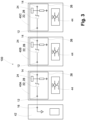
- Fig. 1 shows a schematic representation of a series connection according to an exemplary embodiment of the present disclosure.
- the series connection is designated here in its entirety with the reference number 100.
- the series connection consists of three individual electrical devices 10A, 10B, and 10C.
- the reference number 10 is used when describing elements common to all electrical devices.
- the electrical devices 10A, 10B and 10C are connected in series for the series connection 100.
- Each device 10 has at least one input 12 and one output 14.
- the input 12 and the output 14 are coupled to one another so that a signal present at the input (input signal) is transmitted to the output (output signal).
- a direct connection of input and output is preferred, but fundamentally not necessary for a series connection.
- the input is followed by an input circuit that receives the input signals and passes them on to a processing unit, which in turn controls an output circuit based on the evaluation of the input signals in order to provide the output signal.
- the input 12 of the first electrical device 10A can be assigned an input signal by an external unit, for example a controller (not shown here).
- the input signal can be a static potential 16, which defines an input voltage 20A at the first device 10A in relation to a reference potential 18.
- the input signal is transmitted from the first electrical device 10A to the output 14.
- the input 12 is preferably connected directly to the output 14 via a discrete electrical circuit, as will be explained below with reference to the description of an individual electrical device.
- the input signal transmitted to the output 14 of the first electrical device 10A forms the input signal of the next electrical device 10B in the series connection.
- the output 14 of the first electrical device 10A can be connected, for example, via an electrical line to the input 12 of the subsequent electrical device 10B.
- the input signal of the electrical device 10B is defined by an input voltage 20B with respect to the reference potential 18. The transmission of the input signal continues in the same way until the last electrical device, to which the input voltage 20C is finally applied.
- the reference potential 18 can also be transmitted in the same way, for example via the additional input and outputs shown here Exits 12' and 14'.
- the reference potential 18 can also be a common ground potential to which the individual electrical devices 10 relate.
- the input voltages 20A, 20B and 20C on the electrical devices 10A, 10B and 10C have a defined relationship to one another, which, as shown below, is defined by the transmission of the input signal from the input 12 to the output 14 within the electrical devices 10 .
- the transmission of the input signal from the input 12 to the output 14 is set up in such a way that a defined, preferably constant, voltage drop occurs between the input 12 and the output 14.
- an electrical component 22 can be connected between input 12 and output 14, which causes the voltage drop ⁇ U.
- the electrical component 22 can be a passive component such as a diode, in particular a Schottky diode.
- the voltage drop is constant and the same in all electrical devices 10A, 10B and 10C.
- the voltage drop can be 300 mV and is therefore low in relation to an input voltage of 20A on the first electrical device of the industry standard 24 V.
- the electrical devices 10 have a measuring device 24.
- the measuring device 24 in the individual devices is set up to measure a current voltage that is present at the electrical device.
- the measuring device 24 can be arranged on the input side in front of the electrical component 22. However, the measuring device 24 is preferably arranged after the electrical component 22, i.e. on the output side.
- the voltage measured by the measuring device 24 directly or indirectly determines a manipulated variable of the respective electrical device.
- the measuring device 24 can be an analog-digital converter (ADC) that assigns a specific digital value to a voltage value. The value determined by the analog-digital converter is then an example of the manipulated variable.
- ADC analog-digital converter
- the series connection of the electrical components 22 results in a cascading voltage drop across the series connection. Those from the measuring device 24 measured voltage is therefore one level lower than the voltage in the previous device. Due to cascading, each device in the series connection has an individual voltage value that determines the respective manipulated variable. With a suitable choice of electrical components 22, it can be achieved that the individual voltage values in the individual electrical devices of the series circuit 100 are unique. Consequently, the manipulated variable can be used to assign a unique identifier to the respective electrical device within the series connection. As will be explained below using a specific example, this unique identifier can be used to carry out a device-specific control function.
- the input/output circuit 26 is an electrical circuit arranged between the input 12 and the output 14 of an electrical device 10 prepared for use in a series connection.
- the input 12 and the output 14 are essentially directly connected to one another with only one passive component 22 in between.
- the passive component 22 in this specific example is a Schottky diode 28.
- the Schottky diode 28 is in the forward direction between the input 12 and the output 14 and, due to the design, causes a small voltage drop ⁇ U between the input 12 and the output 14.
- the use of a Schottky diode 28 has the advantage that a small voltage drop can be easily set, which can occur under various external influences and Environmental conditions remain largely the same. It goes without saying that the voltage drop can also be realized by another electrical component.
- the input/output circuit 26 also has a measuring point 30 in the connection between input 12 and output 14, to which the measuring device 24 is coupled.
- the measuring device 24 here is an ADC of a microcontroller 32, not shown in detail.
- the measuring point 30 is arranged on the output side, ie between the electrical component 22 and the output 14. In another embodiment, the measuring point 30 can also be arranged in front of the diode, ie towards the side of the input 12.
- a resistor 34 is also arranged in the input/output circuit 26. This serves as a series resistor for the electrical component 22 (diode) and determines or limits the current through the electrical component 22 and consequently the resulting voltage drop.
- the electrical device 10 has a functional part 36, which performs the actual task of the electrical device 10.
- the functional part 36 can have a processing unit 38 which carries out a control function depending on the input signal present at the input 12.
- the processing unit 38 can be set up to control the control function depending on the manipulated variable determined via the measuring device 24.
- the control function is therefore preferably implemented as a function of both the input signal and the specific manipulated variable.
- the processing unit 38 can be, for example, the microcontroller 32, which, among other things, also provides the ADC for the measuring device 24.
- the processing unit 38 can also have a memory 39 in which the previously determined manipulated variable can be stored.
- the manipulated variable is preferably determined continuously, so that no storage of the manipulated variable is necessary.
- the electrical devices 10 can have different functional parts 36 for different tasks and only the input/output circuits 26 in these devices 10 are constructed identically. In addition, it is not necessary that every device 10 actually makes use of the manipulated variable. This means that both devices 10 that rely on the manipulated variable and other devices in the series connection can be used together.
- Fig. 3 shows a concrete example of a series connection in the sense of the present disclosure, in which locking switches, as are known from automation technology, are connected in series as electrical devices 10.
- Interlocking switches are used, for example, in machines and systems that have dangerous movements or conditions and, in accordance with applicable regulations, may not be operated without a protective device in order to prevent danger to people working on them.
- a machine or system is arranged, for example, in a fenced area or in a housing.
- a door or a cover or the like is provided in order to be able to carry out work on the machine or system or to insert or remove a workpiece despite the separating protective devices. It must be ensured that the door or cover cannot be opened while the machine or system is in operation or, if this is attempted, a forced shutdown is caused.
- locking devices with guard locking must be used in systems with trailing, dangerous movements. These keep the door or cover closed even after the machine has been switched off until the drives of the machine or system come to a standstill. Only then can the door or cover be opened.
- interlocking switches are often operated in a series connection in order to keep cabling work as low as possible.
- the interlocking switches work both as a sensor and, if a tumbler is required, at the same time as an actuator that effects the tumbler.
- a lifting magnet is regularly used as an actuator in locking switches, which can be switched by the locking switch depending on an input signal.
- locking switches with tumblers are arranged in a series connection, it can happen that all actuators are switched at the same time in order to control the lifting magnets. In this case, a high voltage drop can occur in individual supply lines and lead to the solenoids not switching or not switching reliably.
- delay elements are arranged in the individual locking switches, which enable time-delayed switching based on a common input signal.
- known locking switches have, for example, a separate input circuit that is detached from the output circuit in the respective device.
- Such switches also have a processing unit that receives the input signal via the input circuit and depending on it of which controls the output circuit. It is possible to provide a delay element in the processing unit, which delays the forwarding of the input signal to the output.
- the processing unit of the individual locking switches can be configured manually or automatically and adapted to the respective series connection, so that time-delayed switching of the actuators can be ensured.
- a controller 42 configured to send an input signal to the series-connected latching switches 40A, 40B and 40C.
- the controller 42 for example a safety controller, monitors the operation of a technical system and controls the locking switches accordingly via the input signal.
- the input signal can be a binary signal that can assume an ON or an OFF state. In the ON state, the input signal corresponds to a defined potential 16, which is present at the input 12 of the first locking switch 40A. In the OFF state, there is no defined potential at input 12, so that input 12 of locking switch 40A is open or high-resistance. It goes without saying that a locking switch can have additional inputs and outputs or interfaces that can be relevant to realizing the desired function.
- the input signal is transmitted from one latch switch 40A, 40B to the next latch switch 40B, 40C in the series connection in the manner previously described.
- the input voltage in each locking switch 40A, 40B, 40C is reduced by an amount that is defined by the electrical component 22.
- the measuring devices 24 in the individual locking switches 40A, 40B, 40C thus each measure a reduced voltage compared to the previous locking switches 40A, 40B, 40C.
- an individual manipulated variable for the locking switches 40A, 40B, 40C can be generated from the measured voltage.
- the manipulated variable can be a time variable, which results, for example, from the following assignment rule.
- t Switch , n f U ADC , n
- t Switching,n is the manipulated variable of the nth device, which results as a function of the voltage U ADC,n measured on the nth device, for example in the form of a multiplication of the measured voltage U ADC,n by a constant conversion factor.
- the manipulated variable can in particular represent a delay time that the locking switch 40 waits after a change at the input 12 before the switch carries out the corresponding control function.
- the control function can be, for example, controlling a magnetic switch 44, as indicated here in the functional part 36 of the locking switch 40.
- the locking switch 40 can thus advantageously derive the switching time directly from the measured voltage without the manipulated variable actually having to be stored in the locking switch.
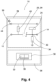
- Fig. 4 shows a further embodiment of an electrical device with a further development of the input/output circuit 26.
- the input/output circuit 26 has, in addition to the previously described elements of the input/output circuit 26 according to Fig. 2 and 3 additionally a connection 46 for receiving a supply potential 50. Furthermore, the circuit has a further resistor 48, which is arranged between the connection 46 and the input 12. More precisely, the resistor 48 is designed as a pull-up resistor and is connected on one side to the supply potential 50 and on the other side between the input 12 and the electrical component 22, which causes the voltage drop.
- the resistor 48 can, for example, be a factor of 10 to 20 higher in resistance than the resistor 34.
- Fig. 5 shows a series circuit 100 with three electrical devices 10A, 10B and 10C connected in series, each of which has an input/output circuit 26 according to FIG Fig. 4 have the version shown.
- the electrical devices 10A, 10B and 10C can, for example, again be the previously described locking switches.
- the series-connected electrical devices 10A, 10B and 10C are each connected to a supply potential 50 provided by the controller 42 at the connection 46.
- the supply potential can also be looped through from one device to the other device.
- the devices in addition to the connection 46, via which they receive the supply potential 50, the devices can have a further connection 52, via which they provide the supply potential 50 again.
- a voltage is also provided in the event that there is no input signal at the input 12 of the first electrical device 10A and this is open, so that a voltage cascade is also formed here via the series connection, which is caused by the voltage drop at the electrical components 22 is caused.
- the measuring devices 24 it is possible to use the measuring devices 24 to determine individual and unique voltage values for the individual electrical devices 10A, 10B and 10C, based on which a manipulated variable can be determined. This development therefore makes it possible to configure a unique manipulated variable in the electrical devices 10A, 10B and 10C even if there is no input voltage at the input 12 of the first device in the series connection.
- the individual electrical devices 10A, 10B and 10C can be configured independently of the presence of an input signal at the input 12 of the first electrical device. In this way, additional applications can be implemented.
- Fig. 6 shows a schematic representation of a method according to an embodiment of the present disclosure. The process is designated in its entirety with the reference number 1000.
- the electrical devices 10 are first provided.
- the electrical devices 10 have an input 12 for applying an input signal, an output 14 for providing an output signal and a measuring device 24 for determining a voltage present at the respective electrical device 10.
- the electrical devices 10 are combined into a series connection 100 by arranging the devices 10 one after the other in a chain.
- the first device can be connected to an input signal and each additional electrical device has its input connected to the output of a previous electrical device in the series connection.
- step 1003 a defined potential is applied to the input of the first electrical device of the series connection, which is transmitted from the first device to the other electrical devices.
- each of the electrical devices lowers the defined potential by a certain amount (defined voltage drop), so that a voltage cascade is created across the series connection.
- each electrical device measures a voltage that is currently present on the respective electrical device via the associated measuring device.
- each electrical device configures a manipulated variable relevant to the device based on the previously measured voltage.
- the method can include further steps or can be carried out in a modified form.
- the provision in step 1001 can also include a reconfiguration of an existing series connection. During a reconfiguration, individual devices can be removed or added. Furthermore, can A reconfiguration also includes swapping individual electrical devices in the series connection. Even if there is a reconfiguration in step 1001, the subsequent steps are carried out in the same way to reconfigure the electrical devices.
- steps 1004 and 1005 are carried out continuously, so that the electrical devices automatically reconfigure as soon as the measured voltage changes due to the voltage cascade.
- This configuration is also advantageous if a series connection, as shown in Fig. 5 is shown, is used, in which the voltage cascade is adjusted sometimes based on the supply voltage and sometimes based on an input signal. In other words, a reconfiguration can occur even if there is no input signal and the input on the first electrical device is open. In this case, the supply voltage takes the place of the input signal via the additional resistor.
- steps 1004 and 1005 are only carried out during this time or, if necessary, triggered manually during commissioning. It is advantageous here if the configured manipulated variable can be stored in a memory of the electrical devices. Manual configuration can be done when the in Fig. 2 and Fig. 3 electrical devices shown can be advantageous.
Landscapes
- Physics & Mathematics (AREA)
- General Physics & Mathematics (AREA)
- Engineering & Computer Science (AREA)
- Automation & Control Theory (AREA)
- General Engineering & Computer Science (AREA)
- Programmable Controllers (AREA)
- Control Of Voltage And Current In General (AREA)
- Dc Digital Transmission (AREA)
Applications Claiming Priority (1)
| Application Number | Priority Date | Filing Date | Title |
|---|---|---|---|
| DE102022120665.3A DE102022120665A1 (de) | 2022-08-16 | 2022-08-16 | Konfiguration in Reihe geschalteter elektrischer Geräte |
Publications (1)
| Publication Number | Publication Date |
|---|---|
| EP4325307A1 true EP4325307A1 (fr) | 2024-02-21 |
Family
ID=87576070
Family Applications (1)
| Application Number | Title | Priority Date | Filing Date |
|---|---|---|---|
| EP23191462.3A Pending EP4325307A1 (fr) | 2022-08-16 | 2023-08-15 | Configuration de dispositifs électriques connectés en serie |
Country Status (5)
| Country | Link |
|---|---|
| US (1) | US20240061387A1 (fr) |
| EP (1) | EP4325307A1 (fr) |
| JP (1) | JP2024027103A (fr) |
| CN (1) | CN117590032A (fr) |
| DE (1) | DE102022120665A1 (fr) |
Citations (3)
| Publication number | Priority date | Publication date | Assignee | Title |
|---|---|---|---|---|
| EP0348810A2 (fr) * | 1988-06-30 | 1990-01-03 | Siemens Aktiengesellschaft | Méthode pour l'adressage d'unités de processeur et circuit pour la mise en oeuvre de la méthode |
| DE4038992C1 (fr) * | 1990-12-06 | 1992-02-06 | Siemens Ag, 8000 Muenchen, De | |
| DE102013018282A1 (de) * | 2013-10-31 | 2015-05-21 | Nxtcontrol Gmbh | Verfahren zur Identifizierung der relativen Einbauposition der in einem modularen elektronischen System zur Verwendung kommenden Module |
Family Cites Families (10)
| Publication number | Priority date | Publication date | Assignee | Title |
|---|---|---|---|---|
| US4580062A (en) * | 1983-04-21 | 1986-04-01 | Cosden Technology, Inc. | Safety shield control device |
| JP2001088952A (ja) * | 1999-09-24 | 2001-04-03 | Ricoh Co Ltd | 画像形成装置 |
| JP2010003038A (ja) * | 2008-06-19 | 2010-01-07 | Koyo Electronics Ind Co Ltd | シリアル接続内での各ユニットのid自動割付方式 |
| JP4957813B2 (ja) * | 2010-01-26 | 2012-06-20 | 株式会社デンソー | 通信用スレーブ及び通信ネットワークシステム |
| US8212432B2 (en) * | 2010-01-29 | 2012-07-03 | Elster Solutions, Llc | Safety interlocks for electricity meter control relays |
| EP2577878A4 (fr) * | 2010-05-28 | 2016-12-07 | Ronen Apelker | Système et procédé de commande de charges automatisé |
| US9371067B2 (en) * | 2011-03-31 | 2016-06-21 | Elite Power Solutions Llc | Integrated battery control system |
| CN105955046A (zh) * | 2016-05-31 | 2016-09-21 | 深圳市君鹏物联科技有限公司 | 一种在物联网中实现多条件控制场景的方法 |
| JP2022073065A (ja) * | 2020-10-30 | 2022-05-17 | キヤノン株式会社 | 開閉検知装置及び画像形成装置 |
| US12111652B2 (en) * | 2021-12-21 | 2024-10-08 | Yahoo Ad Tech Llc | Electrical distribution system |
-
2022
- 2022-08-16 DE DE102022120665.3A patent/DE102022120665A1/de active Pending
-
2023
- 2023-08-14 JP JP2023131774A patent/JP2024027103A/ja active Pending
- 2023-08-15 CN CN202311025369.3A patent/CN117590032A/zh active Pending
- 2023-08-15 EP EP23191462.3A patent/EP4325307A1/fr active Pending
- 2023-08-16 US US18/450,867 patent/US20240061387A1/en not_active Abandoned
Patent Citations (3)
| Publication number | Priority date | Publication date | Assignee | Title |
|---|---|---|---|---|
| EP0348810A2 (fr) * | 1988-06-30 | 1990-01-03 | Siemens Aktiengesellschaft | Méthode pour l'adressage d'unités de processeur et circuit pour la mise en oeuvre de la méthode |
| DE4038992C1 (fr) * | 1990-12-06 | 1992-02-06 | Siemens Ag, 8000 Muenchen, De | |
| DE102013018282A1 (de) * | 2013-10-31 | 2015-05-21 | Nxtcontrol Gmbh | Verfahren zur Identifizierung der relativen Einbauposition der in einem modularen elektronischen System zur Verwendung kommenden Module |
Also Published As
| Publication number | Publication date |
|---|---|
| US20240061387A1 (en) | 2024-02-22 |
| CN117590032A (zh) | 2024-02-23 |
| JP2024027103A (ja) | 2024-02-29 |
| DE102022120665A1 (de) | 2024-02-22 |
Similar Documents
| Publication | Publication Date | Title |
|---|---|---|
| EP1269274B2 (fr) | Interrupteur de securite et procede pour ajuster un mode de fonctionnement pour interrupteur de securite | |
| DE1927166A1 (de) | Vorrichtung,Verfahren und elektrischer Kreis zur UEberwachung einer Mehrzahl von elektrischen Steuerpulten durch einen Komputer | |
| WO2009068164A1 (fr) | Circuit et procédé pour réguler l'alimentation électrique d'un consommateur avec des impulsions de courant présentant des flancs raides | |
| EP3111284B1 (fr) | Circuit d'entrée à redondance, unité de circuit d'entrée comprenant au moins un circuit d'entrée et procédé servant à faire fonctionner une unité de circuit d'entrée de ce type | |
| EP0519089B1 (fr) | Introduction de paramètres de service dans un commutateur de proximité prêt à servir | |
| DE2321200B2 (de) | Schaltungsanordnung zur Durchführung logischer Verknüpfungen | |
| EP4325307A1 (fr) | Configuration de dispositifs électriques connectés en serie | |
| EP3652860B1 (fr) | Convertisseur de niveau et procédé de conversion de valeurs de niveau dans des dispositifs de commande de véhicule | |
| DE4420988A1 (de) | Verfahren zum Testen einer integrierten Schaltung sowie integrierte Schaltungsanordnung mit einer Testschaltung | |
| WO2011009467A1 (fr) | Circuit de commande pour cellule de pockels | |
| DE10163393B4 (de) | Anschlusselement für einen Bus | |
| DE2906937A1 (de) | Steuersystem zur steuerung eines geraetes mit einer vielzahl von maschinenfunktionen | |
| DE102014202077A1 (de) | Digitale Schaltung zur Erzeugung eines pulsweitenmodulierten Signals, insbesondere zur Regelung einer analogen Größe | |
| DE10331544B3 (de) | Verfahren zum Ansteuern eines Transistors | |
| EP0689291B1 (fr) | Circuit d'attaque du type MOS | |
| DE3636154A1 (de) | Verbesserter verzoegerungsschaltkreis fuer inverter | |
| DE2365237A1 (de) | Automatische steuerungseinrichtung | |
| DE19913140C2 (de) | Elektrische integrierte Schaltung | |
| DE102024108102A1 (de) | Erkennung von schaltzuständen durch abbildung der schaltzustände auf ein an einem analogen eingang einlesbares potenzial | |
| DE2213921C2 (de) | Elektronisches kurzschlußsicheres Schaltersystem | |
| DE2520822C3 (de) | Integrierte Schaltung in MOS-Technik für Richtimpulsgeber | |
| DE19906860A1 (de) | Tristate-Differenz-Ausgangsstufe | |
| DE2606983C2 (de) | Halbleiterbaustein aus integrierten Transistoren, insbesondere für Steuereinrichtungen von Fernsprechvermittlungsanlagen | |
| DE19959405A1 (de) | Umkonfigurierbare Geräteschnittstelle | |
| DE102019217743A1 (de) | Fluidanordnung |
Legal Events
| Date | Code | Title | Description |
|---|---|---|---|
| PUAI | Public reference made under article 153(3) epc to a published international application that has entered the european phase |
Free format text: ORIGINAL CODE: 0009012 |
|
| STAA | Information on the status of an ep patent application or granted ep patent |
Free format text: STATUS: THE APPLICATION HAS BEEN PUBLISHED |
|
| AK | Designated contracting states |
Kind code of ref document: A1 Designated state(s): AL AT BE BG CH CY CZ DE DK EE ES FI FR GB GR HR HU IE IS IT LI LT LU LV MC ME MK MT NL NO PL PT RO RS SE SI SK SM TR |
|
| STAA | Information on the status of an ep patent application or granted ep patent |
Free format text: STATUS: REQUEST FOR EXAMINATION WAS MADE |
|
| 17P | Request for examination filed |
Effective date: 20240819 |
|
| RBV | Designated contracting states (corrected) |
Designated state(s): AL AT BE BG CH CY CZ DE DK EE ES FI FR GB GR HR HU IE IS IT LI LT LU LV MC ME MK MT NL NO PL PT RO RS SE SI SK SM TR |
|
| STAA | Information on the status of an ep patent application or granted ep patent |
Free format text: STATUS: EXAMINATION IS IN PROGRESS |