EP4325664A9 - Dispositif de découplage et procédé de découplage - Google Patents
Dispositif de découplage et procédé de découplage Download PDFInfo
- Publication number
- EP4325664A9 EP4325664A9 EP22798553.8A EP22798553A EP4325664A9 EP 4325664 A9 EP4325664 A9 EP 4325664A9 EP 22798553 A EP22798553 A EP 22798553A EP 4325664 A9 EP4325664 A9 EP 4325664A9
- Authority
- EP
- European Patent Office
- Prior art keywords
- decoupling
- plane
- metal patch
- metal
- unit
- Prior art date
- Legal status (The legal status is an assumption and is not a legal conclusion. Google has not performed a legal analysis and makes no representation as to the accuracy of the status listed.)
- Pending
Links
Images






Classifications
-
- H—ELECTRICITY
- H01—ELECTRIC ELEMENTS
- H01Q—ANTENNAS, i.e. RADIO AERIALS
- H01Q1/00—Details of, or arrangements associated with, antennas
- H01Q1/52—Means for reducing coupling between antennas; Means for reducing coupling between an antenna and another structure
- H01Q1/521—Means for reducing coupling between antennas; Means for reducing coupling between an antenna and another structure reducing the coupling between adjacent antennas
- H01Q1/523—Means for reducing coupling between antennas; Means for reducing coupling between an antenna and another structure reducing the coupling between adjacent antennas between antennas of an array
-
- H—ELECTRICITY
- H01—ELECTRIC ELEMENTS
- H01Q—ANTENNAS, i.e. RADIO AERIALS
- H01Q21/00—Antenna arrays or systems
- H01Q21/06—Arrays of individually energised antenna units similarly polarised and spaced apart
- H01Q21/061—Two dimensional planar arrays
- H01Q21/062—Two dimensional planar arrays using dipole aerials
-
- H—ELECTRICITY
- H01—ELECTRIC ELEMENTS
- H01Q—ANTENNAS, i.e. RADIO AERIALS
- H01Q1/00—Details of, or arrangements associated with, antennas
- H01Q1/52—Means for reducing coupling between antennas; Means for reducing coupling between an antenna and another structure
- H01Q1/521—Means for reducing coupling between antennas; Means for reducing coupling between an antenna and another structure reducing the coupling between adjacent antennas
-
- H—ELECTRICITY
- H01—ELECTRIC ELEMENTS
- H01Q—ANTENNAS, i.e. RADIO AERIALS
- H01Q15/00—Devices for reflection, refraction, diffraction or polarisation of waves radiated from an antenna, e.g. quasi-optical devices
- H01Q15/0006—Devices acting selectively as reflecting surface, as diffracting or as refracting device, e.g. frequency filtering or angular spatial filtering devices
- H01Q15/0013—Devices acting selectively as reflecting surface, as diffracting or as refracting device, e.g. frequency filtering or angular spatial filtering devices said selective devices working as frequency-selective reflecting surfaces, e.g. FSS, dichroic plates, surfaces being partly transmissive and reflective
-
- H—ELECTRICITY
- H01—ELECTRIC ELEMENTS
- H01Q—ANTENNAS, i.e. RADIO AERIALS
- H01Q21/00—Antenna arrays or systems
- H01Q21/06—Arrays of individually energised antenna units similarly polarised and spaced apart
- H01Q21/061—Two dimensional planar arrays
-
- H—ELECTRICITY
- H01—ELECTRIC ELEMENTS
- H01Q—ANTENNAS, i.e. RADIO AERIALS
- H01Q21/00—Antenna arrays or systems
- H01Q21/28—Combinations of substantially independent non-interacting antenna units or systems
-
- H—ELECTRICITY
- H01—ELECTRIC ELEMENTS
- H01Q—ANTENNAS, i.e. RADIO AERIALS
- H01Q5/00—Arrangements for simultaneous operation of antennas on two or more different wavebands, e.g. dual-band or multi-band arrangements
- H01Q5/30—Arrangements for providing operation on different wavebands
- H01Q5/307—Individual or coupled radiating elements, each element being fed in an unspecified way
- H01Q5/342—Individual or coupled radiating elements, each element being fed in an unspecified way for different propagation modes
- H01Q5/357—Individual or coupled radiating elements, each element being fed in an unspecified way for different propagation modes using a single feed point
- H01Q5/364—Creating multiple current paths
-
- H—ELECTRICITY
- H01—ELECTRIC ELEMENTS
- H01Q—ANTENNAS, i.e. RADIO AERIALS
- H01Q9/00—Electrically-short antennas having dimensions not more than twice the operating wavelength and consisting of conductive active radiating elements
- H01Q9/04—Resonant antennas
- H01Q9/16—Resonant antennas with feed intermediate between the extremities of the antenna, e.g. centre-fed dipole
- H01Q9/28—Conical, cylindrical, cage, strip, gauze, or like elements having an extended radiating surface; Elements comprising two conical surfaces having collinear axes and adjacent apices and fed by two-conductor transmission lines
- H01Q9/285—Planar dipole
Definitions
- the present disclosure relates to the technical field of wireless communication, in particular to a decoupling device and a decoupling method.
- the multiple input multiple output (MIMO) antenna technology implemented in the fifth-generation (5G) mobile communication, is regarded as one of the core technologies of 5G owing to its ability to enhance the reliability of communication systems and expand channel capacity.
- Antenna mutual coupling as a widely prevalent physical phenomenon, will significantly deteriorate the performance of a MIMO antenna system, causing problems such as increased independent channel correlation, deteriorated active standing waves, decreased gain, and deteriorated signal-to-noise ratio.
- an antenna array is required to be miniaturized, which further enhances mutual coupling. Therefore, reducing antenna mutual coupling has become the focus of Massive-MIMO antenna research.
- the coupling modes can be classified into an E-plane coupling mode, an H-plane coupling mode and a diagonal coupling mode that lies between the E-plane coupling mode and the H-plane coupling mode, based on the relative position relationship between antenna elements.
- Existing decoupling techniques can only realize decoupling in a single coupling mode.
- the present disclosure aims at solving one of the technical problems present in certain scenarios at least to some extent, and provides a decoupling device and a decoupling method.
- an embodiment provides a decoupling device applied to an antenna array, the antenna array includes a plurality of antenna elements, and the decoupling device includes: a dielectric substrate located above the plurality of antenna elements; first decoupling units arranged on the dielectric substrate, each first decoupling unit being located above a middle position between every two E-plane coupled antenna elements; second decoupling units arranged on the dielectric substrate, the second decoupling units being located above each antenna element; and third decoupling units arranged on the dielectric substrate, each third decoupling unit being located above a middle position between every two H-plane coupled antenna elements.
- an embodiment provides a decoupling method applied to an antenna array, the antenna array includes a plurality of antenna elements, and the decoupling method includes: providing a first decoupling unit above a middle position between every two E-plane coupled antenna elements; providing a second decoupling unit above each antenna element; and providing a third decoupling unit above a middle position between every two H-plane coupled antenna elements.
- the meaning of “several” is one or a plurality; the meaning of "a plurality of” is two or more; “greater than”, “less than”, “more than”, etc. are to be construed as excluding a given figure; and “above”, “below”, “within”, etc. are to be construed as including a given figure. If “first” and “second”, etc. are referred to, it is only for the purpose of distinguishing technical features, and shall not be construed as indicating or implying relative importance or implying the number of the indicated technical features or implying the sequence of the indicated technical features.
- An embodiment of the present disclosure provides a decoupling device and a decoupling method to realize both E-plane decoupling and H-plane decoupling for an antenna array.
- An embodiment of a first aspect of the present disclosure provides a decoupling device applied to an antenna array.
- the antenna array includes a plurality of antenna elements.
- the antenna array in this embodiment is a 2 ⁇ 2 planar antenna array 200, which is placed on a reflective floor 300 as shown in FIGS. 2 and 3 .
- the planar antenna array 200 includes a first antenna element 210, a second antenna element 220, a third antenna element 230 and a fourth antenna element 240.
- the first antenna element 210 and the second antenna element 220 are two antenna elements coupled in the H-plane
- the second antenna element 220 and the third antenna element 230 are two antenna elements coupled in the E-plane.
- the third antenna element 230 and the fourth antenna element 240 are two antenna elements coupled in the H-plane
- the first antenna element 210 and the fourth antenna element 240 are two antenna elements coupled in the E-plane.
- the decoupling device 100 covers the planar antenna array 200, and includes a dielectric substrate 110, first decoupling units 120, second decoupling units 130 and third decoupling units 140.
- the dielectric substrate 110 is located above the plurality of antenna elements, that is, above the planar antenna array 200, the dielectric substrate 110 only serves as a physical support for the first decoupling units 120, the second decoupling units 130 and the third decoupling units 140, and the dielectric substrate 110 may be of a one-layer or multi-layer structure. In some possible implementations, the dielectric substrate 110 may also be an antenna housing.
- the first decoupling units 120 are arranged on the dielectric substrate 110, and each first decoupling unit 120 is located above a middle position between every two E-plane coupled antenna elements, that is, one first decoupling unit 120 is arranged above the middle position between the second antenna element 220 and the third antenna element 230, and the other first decoupling unit 120 is arranged above the middle position between the first antenna element 210 and the fourth antenna element 240.
- the second decoupling units 130 are arranged on the dielectric substrate 110, and the second decoupling units 130 are located above each antenna element, that is, the second decoupling units 130 are arranged above the first antenna element 210, the second antenna element 220, the third antenna element 230 and the fourth antenna element 240 respectively.
- the third decoupling units 140 are arranged on the dielectric substrate 110, and each third decoupling unit 140 is located above a middle position between every two H-plane coupled antenna elements, that is, one third decoupling unit 140 is arranged above the middle position between the first antenna element 210 and the second antenna element 220, and the other third decoupling unit 140 is arranged above the middle position between the third antenna element 230 and the fourth antenna element 240.
- the first decoupling units 120 are arranged above the middle positions between every two E-plane coupled antenna elements and the second decoupling units 130 are arranged above each antenna element, E-plane scattered waves with equal amplitude and opposite phase to E-plane coupled waves are generated by the first decoupling units 120 and the second decoupling units 130, and the E-plane scattered waves and the E-plane coupled waves cancel each other out to realize E-plane decoupling; in addition, the second decoupling units 130 will also generate H-plane scattered waves to realize partial H-plane decoupling; furthermore, the third decoupling units 140 are arranged above the middle positions between every two H-plane coupled antenna elements, H-plane scattered waves with equal amplitude and opposite phase to H-plane coupled waves are generated by the second decoupling units 130 and the third decoupling units 140, and the H-plane scattered waves and the H-plane coupled waves cancel each other out to realize H-plane decoupling; and through the joint action of the first decoupling units 120
- the first decoupling unit 120 includes a first metal patch 121 or a plurality of first metal patches 121 arranged in an H-plane direction, and a geometric center of the first decoupling unit 120 is located directly above the middle position between the two corresponding E-plane coupled antenna elements.
- each first decoupling unit 120 includes two first metal patches 121 arranged along the H-plane direction, that is, there are two first metal patches 121 arranged in the horizontal direction above the middle position between the second antenna element 220 and the third antenna element 230, and there are also two first metal patches 121 arranged in the horizontal direction above the middle position between the first antenna element 210 and the fourth antenna element 240.
- the first decoupling unit 120 can also include only one first metal patch 121, or three or more first metal patches 121, which is not limited in this application, as long as the geometric center of the first decoupling unit 120 is located directly above the middle position between two E-plane coupled antenna elements.
- the first metal patch 121 may be rectangular, triangular, circular, cross-shaped, I-shaped, C-shaped or in other similar shapes.
- a length of the first metal patch 121 in the H-plane direction ranges from 0.01 ⁇ c to 0.25 ⁇ c, where ⁇ c is a wavelength of electromagnetic waves corresponding to a central frequency of the antenna array.
- the first metal patch 121 in this size range is an electrically small metal patch. Electromagnetic scattered waves of the electrically small metal patch structure are isotropic, meaning that the amplitudes and phases of scattered waves in different directions are equal at the same distance.
- the first metal patch 121 is sleeved with a first metal ring 122.
- the first metal patch 121 can be of a single metal patch structure, or an internal nested structure, and the internal nested structure refers to a structure in which the first metal patch 121 is sleeved with a first metal ring 122.
- the nested metal patch structure helps increase the amplitude of the scattered waves and improve the decoupling effect.
- each first metal patch 121 includes a plurality of metal patch pieces arranged in a direction perpendicular to the H-plane direction.
- each first metal patch 121 includes a plurality of metal patch pieces arranged in the direction perpendicular to the H-plane direction, that is, the first decoupling unit 120 is formed by arranging a plurality of metal patch pieces in a two-dimensional array.
- the first decoupling unit 120 includes two first metal patches 121 arranged in the H-plane direction, and each first metal patch 121 includes two metal patch pieces arranged in the direction perpendicular to the H-plane direction, that is, the first decoupling unit 120 is formed by arranging four metal patch pieces in a two-dimensional array.
- each first metal patch 121 includes a plurality of metal patch pieces stacked in layers.
- the first metal patch 121 is formed by the plurality of stacked metal patch pieces to form a three-dimensional spatial structure, which can achieve different decoupling effects.
- the second decoupling unit 130 includes a second metal patch 131 or a plurality of second metal patches 131 arranged in an E-plane direction, and a geometric center of the second decoupling unit 130 is located directly above the corresponding antenna element.
- each second decoupling unit 130 includes two second metal patches 131 arranged in the E-plane direction, that is, there are two second metal patches 131 arranged in the vertical direction above each of the first antenna element 210, the second antenna element 220, the third antenna element 230 and the fourth antenna element 240.
- the second decoupling unit 130 can also include only one second metal patch 131, or three or more second metal patches 131, which is not limited in this application, as long as the geometric center of the second decoupling unit 130 is located directly above the corresponding antenna element.
- the second metal patch 131 may be rectangular, triangular, circular, cross-shaped, I-shaped, C-shaped or in other similar shapes.
- a length of the second metal patch 131 in the E-plane direction ranges from 0.01 ⁇ c to 0.25 ⁇ c, where ⁇ c is a wavelength of electromagnetic waves corresponding to a central frequency of the antenna array.
- the second metal patch 131 in this size range is an electrically small metal patch. Electromagnetic scattered waves of the electrically small metal patch structure are isotropic, meaning that the amplitudes and phases of scattered waves in different directions are equal at the same distance.
- the second metal patch 131 is sleeved with a second metal ring 132.
- the second metal patch 131 can be of a single metal patch structure, or an internal nested structure, and the internal nested structure refers to a structure in which the second metal patch 131 is sleeved with a second metal ring 132.
- the nested metal patch structure helps increase the amplitude of the scattered waves and improve the decoupling effect.
- each second metal patch 131 includes a plurality of metal patch pieces arranged in a direction perpendicular to the E-plane direction.
- each second metal patch 131 includes a plurality of metal patch pieces arranged in the direction perpendicular to the E-plane direction, that is, the second decoupling unit 130 is formed by arranging a plurality of metal patch pieces in a two-dimensional array.
- the second decoupling unit 130 includes two second metal patches 131 arranged in the E-plane direction, and each second metal patch 131 includes two metal patch pieces arranged in the direction perpendicular to the E-plane direction, that is, the second decoupling unit 130 is formed by arranging four metal patch pieces in a two-dimensional array.
- each second metal patch 131 includes a plurality of metal patch pieces stacked in layers.
- the second metal patch 131 is formed by the plurality of stacked metal patch pieces to form a three-dimensional spatial structure, which can achieve different decoupling effects.
- the third decoupling unit 140 includes a third metal patch 141 or a plurality of third metal patches 141 stacked in layers, and a geometric center of the third decoupling unit 140 is located directly above the middle position between the two corresponding H-plane coupled antenna elements.
- the third decoupling unit 140 can be composed of only one third metal patch 141, or a plurality of third metal patches 141 stacked in layers to achieve different decoupling effects.
- the third metal patch 141 may be rectangular, triangular, circular, cross-shaped, I-shaped, C-shaped or in other similar shapes.
- a length of the third metal patch 141 in the H-plane direction ranges from 0.40 ⁇ c to 0.80 ⁇ c, where ⁇ c is a wavelength of electromagnetic waves corresponding to a central frequency of the antenna array.
- the third metal patch 141 in this size range is an electrically large metal patch, and the electrically large size refers to both the physical length and the length through which an effective current flows, that is, electrical length.
- the third metal patch 141 is sleeved with a third metal ring 142.
- the third metal patch 141 can be of a single metal patch structure, or an internal nested structure, and the internal nested structure refers to a structure in which the third metal patch 141 is sleeved with a third metal ring 142.
- the nested metal patch structure helps reduce the physical size of the electrically large metal patch, increase the amplitude of the scattered waves and improve the decoupling effect.
- first decoupling unit 120, the second decoupling unit 130 and the third decoupling unit 140 can be at the same height or at different heights.
- the first decoupling unit 120, the second decoupling unit 130, and the third decoupling unit 140 are positioned at a height between 0.05 ⁇ c and 1.0 ⁇ c from the antenna elements.
- a size of the first decoupling unit 120 increases with the decrease of a distance between every two E-plane coupled antenna elements, but does not exceed a distance between two H-plane coupled antenna elements.
- a size of the second decoupling unit 130 increases as a distance between every two E-plane-coupled antenna elements decreases or as a distance between every two H-plane-coupled antenna elements decreases, but does not exceed the distance between two E-plane-coupled antenna elements.
- a size of the third decoupling unit 140 is determined by the operating frequency of antennas, and is independent of the distance between the antenna elements.
- the first decoupling unit 120, the second decoupling unit 130 and the third decoupling unit 140 can be extended along an x axis and a y axis according to a scale of the planar antenna array, making them suitable for antenna arrays with any number of antenna elements.
- the planar antenna array 200 is placed on a reflective floor 300, the spacing between antenna elements in an x-axis direction is 47 mm (0.55 ⁇ 3.5 GHz ), and the spacing in a y-axis direction is 43 mm (0.5 ⁇ 3.5 GHz ).
- the antenna element is a printed electric dipole antenna.
- the first decoupling unit 120, the second decoupling unit 130 and the third decoupling unit 140 are all etched on an upper surface of the dielectric substrate 110.
- the first decoupling unit 120 is composed of two electrically small first metal patches 121, and the first metal patches 121 are arranged in an H-plane direction of the antenna. Geometric centers of the first decoupling units 120 are located directly above middle positions between every two E-plane coupled antenna elements.
- the second decoupling unit 130 is composed of two electrically small second metal patches 131. To avoid excessive influence on the decoupling effect of the first decoupling unit 120, the second metal patches 131 are arranged in an E-plane direction of the antenna from two ends of the antenna element. Geometric centers of the second decoupling units 130 are located directly above each antenna element.
- the third decoupling unit 140 is composed of an electrically large third metal patch 141, and geometric centers of the third decoupling units 140 are located above middle positions between every two H-plane coupled antenna elements.
- the first metal patch 121 has a length L1 of 16 mm (0.19 ⁇ 3.5 GHz ) and a width W1 of 8 mm (0.09 ⁇ 3.5 GHz ).
- the second metal patch 131 has a length L2 of 19 mm (0.22 ⁇ 3.5 GHz ) and a width W2 of 8 mm (0.09 ⁇ 3.5 GHz ).
- the third metal patch 141 has a length L3+L4 of 46 mm (0.54 ⁇ 3.5 GHz ) and a width W3 of 6 mm (0.07 ⁇ 3.5 GHz ).
- the first decoupling unit 120, the second decoupling unit 130 and the third decoupling unit 140 are located at the same height, with a distance H of 14 mm from the antenna array 200 (0.16 ⁇ 3.5 GHz ).
- the first metal patch 121 is a rectangular metal patch, and sleeved with a first metal ring 122 to enhance the amplitude of scattered waves.
- the second metal patch 131 is a rectangular metal patch, and sleeved with a second metal ring 132 to enhance the amplitude of scattered waves.
- the third metal patch 141 is a cross-shaped metal patch, and sleeved with a cross-shaped third metal ring 142 to reduce the physical size of the electrically large metal patch and enhance the amplitude of scattered waves.
- first metal patch 121 and the second metal patch 131 can be made in shapes other than rectangle and can have different types of structures other than annular nested structure.
- the third metal patch 141 can be made in shapes other than cross shape and can have different types of structures other than annular nested structure.
- the decoupling device 100 can be fixed above the planar antenna array through plastic supports, or can be arranged inside an antenna housing.
- the decoupling device 100 provided by this example which is applied to a planar antenna array to realize dual-mode decoupling, can improve impedance characteristics and radiation characteristics of antennas on the basis of significantly reducing E-plane and H-plane mutual coupling of MIMO antennas.
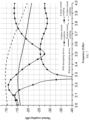
- FIG. 7 which is a graph of mutual coupling before and after using the decoupling device, it can be seen that E-plane and H-plane mutual coupling can be reduced by more than 10 dB within a relative bandwidth of 6% (3.4 to 3.6 GHz), and E-plane and H-plane mutual coupling can be reduced by more than 5 dB within a relative bandwidth of 12% (3.3 to 3.7 GHz); from FIG.
- FIG. 8 which is a graph of return loss before and after using the decoupling device, it can be seen that an impedance bandwidth of antennas can be increased from 5.7% (3.4 to 3.6 GHz) to 14.5% (3.2 to 3.7 GHz); from FIG. 9 which is a directional diagram before and after using the decoupling device, it can be seen that antenna gain can be increased from 8.0 dBi to 8.3 dBi; and from FIG. 10 which is a diagram of active standing waves before and after using the decoupling device, it can be seen that a maximum active standing wave of MIMO antennas can be reduced from 1.9 to 1.55 when a beam is oriented at 0°, and from 3.3 to 1.6 when a beam is oriented at 15°.
- the decoupling device 100 can be extended periodically along the x-axis and the y-axis, and is applicable to planar MIMO antennas with any number of antenna elements.
- the decoupling device 100 can cover the MIMO antennas and be integrated inside an antenna housing, and features a simple structure, convenient implementation and low cost.
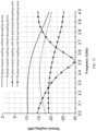
- FIG. 11 is a graph of E-plane and H-plane mutual coupling when the first decoupling units and the second decoupling units are used. After using the first decoupling units and the second decoupling units, in the frequency range of 3.4 to 3.6 GHz, E-plane mutual coupling is reduced by 10 dB, and H-plane mutual coupling is only reduced by 4 dB.
- the third decoupling units change a phase of the H-plane scattered waves generated by the second decoupling units by means of resonance characteristics of the electrically large metal patch, making the H-plane scattered waves generated by the second decoupling units and the third decoupling units equal in amplitude and opposite in phase to the H-plane coupled waves, thus realizing H-plane decoupling.
- the third decoupling units are located apart from the E-plane coupled antennas, and will not affect E-plane decoupling. As shown in FIG. 7 , after using the first decoupling units, the second decoupling units and the third decoupling units, H-plane mutual coupling is less than 25 dB, which is 10 dB lower than that without a decoupling device.
- FIG. 12 shows a graph of H-plane mutual coupling varying with the size of the electrically large metal patch in a two-element sub-array. As the size of the electrically large metal patch becomes larger, an optimal decoupling frequency band of the H-plane moves to low frequency.
- both E-plane decoupling and H-plane decoupling are realized for the antennas.
- an embodiment of a second aspect of the present disclosure provides a decoupling method applied to an antenna array, the antenna array includes a plurality of antenna elements, and the decoupling method includes the following steps:
- the first decoupling units are arranged above the middle positions between every two E-plane coupled antenna elements and the second decoupling units are arranged above each antenna element, E-plane scattered waves with equal amplitude and opposite phase to E-plane coupled waves are generated by the first decoupling units and the second decoupling units, and the E-plane scattered waves and the E-plane coupled waves cancel each other out to realize E-plane decoupling; in addition, the second decoupling units will also generate H-plane scattered waves to realize partial H-plane decoupling; furthermore, the third decoupling units are arranged above the middle positions between every two H-plane coupled antenna elements, H-plane scattered waves with equal amplitude and opposite phase to H-plane coupled waves are generated by the second decoupling units and the third decoupling units, and the H-plane scattered waves and the H-plane coupled waves cancel each other out to realize H-plane decoupling; and through the joint action of the first decoupling units, the second decoupling units and the
- the first decoupling unit includes a first metal patch or a plurality of first metal patches arranged in an H-plane direction, and a geometric center of the first decoupling unit is located directly above the middle position between the two corresponding E-plane coupled antenna elements.
- the first metal patch may be rectangular, triangular, circular, cross-shaped, I-shaped, C-shaped or in other similar shapes, and a size of the first metal patch ranges from 0.01 ⁇ c to 0.25 ⁇ c, where ⁇ c is a wavelength of electromagnetic waves corresponding to a central frequency of the antenna array.
- the first metal patch in this size range is an electrically small metal patch. Electromagnetic scattered waves of the electrically small metal patch structure are isotropic, meaning that the amplitudes and phases of scattered waves in different directions are equal at the same distance.
- the first metal patch can be sleeved with a first metal ring, or each first metal patch includes a plurality of metal patch pieces arranged in a direction perpendicular to the H-plane direction, or each first metal patch includes a plurality of metal patch pieces stacked in layers, and the first metal patch with different structures can achieve different decoupling effects.
- the decoupling method further includes the following step:
- E-plane scattered waves generated by the first decoupling units are equal in amplitude and opposite in phase to E-plane coupled waves, and the E-plane scattered waves and the E-plane coupled waves cancel each other out to realize E-plane decoupling.
- the second decoupling unit includes a second metal patch or a plurality of second metal patches arranged in an E-plane direction, and a geometric center of the second decoupling unit is located directly above the corresponding antenna element.
- the second metal patch may be rectangular, triangular, circular, cross-shaped, I-shaped, C-shaped or in other similar shapes, and a size of the second metal patch ranges from 0.01 ⁇ c to 0.25 ⁇ c, where ⁇ c is a wavelength of electromagnetic waves corresponding to a central frequency of the antenna array.
- the second metal patch in this size range is an electrically small metal patch. Electromagnetic scattered waves of the electrically small metal patch structure are isotropic, meaning that the amplitudes and phases of scattered waves in different directions are equal at the same distance.
- the second metal patch can be sleeved with a second metal ring, or each second metal patch includes a plurality of metal patch pieces arranged in a direction perpendicular to the E-plane direction, or each second metal patch includes a plurality of metal patch pieces stacked in layers, and the second metal patch with different structures can achieve different decoupling effects.
- the decoupling method further includes the following step:
- H-plane scattered waves generated by the second decoupling units can realize partial H-plane decoupling.
- the third decoupling unit includes a third metal patch or a plurality of third metal patches stacked in layers, and a geometric center of the third decoupling unit is located directly above the middle position between the two corresponding H-plane coupled antenna elements.
- the third decoupling unit can be composed of only one third metal patch, or a plurality of third metal patches stacked in layers to achieve different decoupling effects.
- the third metal patch may be rectangular, triangular, circular, cross-shaped, I-shaped, C-shaped or in other similar shapes, and a size of the third metal patch ranges from 0.40 ⁇ c to 0.80 ⁇ c, where ⁇ c is a wavelength of electromagnetic waves corresponding to a central frequency of the antenna array.
- the third metal patch in this size range is an electrically large metal patch, and the electrically large size refers to both the physical length and the length through which an effective current flows, that is, electrical length.
- the third metal patch can be sleeved with a third metal ring.
- the nested metal patch structure helps reduce the physical size of the electrically large metal patch, increase the amplitude of the scattered waves and improve the decoupling effect.
- the decoupling method further includes the following step:
- H-plane scattered waves equal in amplitude and opposite in phase to H-plane coupled waves are generated by the second decoupling units and the third decoupling units, and the H-plane scattered waves and the H-plane coupled waves cancel each other out to realize H-plane decoupling.
- the method for realizing dual-mode decoupling applied to a planar antenna array includes the following steps.
- first decoupling units 120 are provided, and the first decoupling unit is composed of an electrically small first metal patch 121 or a plurality of electrically small first metal patches 121.
- the plurality of first metal patches 121 are arranged in an H-plane direction of antennas, and geometric centers of the first decoupling units 120 are located directly above middle positions between every two E-plane coupled antenna elements.
- E-plane scattered waves generated by the first decoupling units 120 are made to be equal in amplitude and opposite in phase to E-plane coupled waves, thus realizing E-plane antenna decoupling.
- second decoupling units 130 are provided, and the second decoupling unit 130 is composed of an electrically small second metal patch 131 or a plurality of electrically small second metal patches 131.
- the plurality of second metal patches 131 are arranged in an E-plane direction of antennas.
- the second metal patches 131 are arranged from outside to inside, starting at two ends of the antenna. Geometric centers of the second decoupling units 130 are located directly above each antenna element.
- step 3 the first decoupling units 120 are optimized, and the size of the first metal patch 121 is adjusted to correct the influence on the E-plane scattered waves caused by the introduction of the second decoupling units 130, so as to ensure E-plane decoupling.
- step 4 third decoupling units 140 are provided, the third decoupling unit 140 is composed of an electrically large third metal patch 141 or a plurality of electrically large third metal patches 141 stacked in layers, and geometric centers of the third decoupling units 140 are located directly above middle positions between every two H-plane coupled antenna elements.
- H-plane scattered waves generated by the second decoupling units 130 are made to be opposite in phase to H-plane coupled waves, thus realizing H-plane antenna decoupling.
- step 5 the second decoupling units 130 are optimized, and the size of the second metal patch 131 is adjusted to correct the influence caused by the introduction of the third decoupling units 140, so as to ensure H-plane decoupling.
- step 6 the first decoupling units 120, the second decoupling units 130 and the third decoupling units 140 are expanded along the x axis and the y axis according to the scale of the planar MIMO antennas, so as to obtain the decoupling device which can realize both E-plane decoupling and H-plane decoupling for the antennas.
- this method is not only applicable to single-polarized antenna arrays but also suitable for dual-polarized antenna arrays.
- the decoupling device and the decoupling method provided by the embodiments of the present disclosure can realize more coupled wave suppression in a dual-polarized MIMO antenna array and obtain a better coupling effect; and decoupling in any direction in a two-dimensional space can be realized, providing greater flexibility for base station antenna decoupling.
- the embodiments of the present disclosure provide the decoupling device and the decoupling method, where the first decoupling units are arranged above the middle positions between every two E-plane coupled antenna elements and the second decoupling units are arranged above each antenna element, E-plane scattered waves with equal amplitude and opposite phase to E-plane coupled waves are generated by the first decoupling units and the second decoupling units, and the E-plane scattered waves and the E-plane coupled waves cancel each other out to realize E-plane decoupling; in addition, the second decoupling units will also generate H-plane scattered waves to realize partial H-plane decoupling; furthermore, the third decoupling units are arranged above the middle positions between every two H-plane coupled antenna elements, H-plane scattered waves with equal amplitude and opposite phase to H-plane coupled waves are generated by the second decoupling units and the third decoupling units, and the H-plane scattered waves and the H-plane coupled waves cancel each other out to realize H-plane decoupling; and through the
Landscapes
- Variable-Direction Aerials And Aerial Arrays (AREA)
- Waveguide Aerials (AREA)
Applications Claiming Priority (2)
| Application Number | Priority Date | Filing Date | Title |
|---|---|---|---|
| CN202110488752.7A CN115313043B (zh) | 2021-05-06 | 2021-05-06 | 解耦装置及解耦方法 |
| PCT/CN2022/085386 WO2022233212A1 (fr) | 2021-05-06 | 2022-04-06 | Dispositif de découplage et procédé de découplage |
Publications (3)
| Publication Number | Publication Date |
|---|---|
| EP4325664A1 EP4325664A1 (fr) | 2024-02-21 |
| EP4325664A9 true EP4325664A9 (fr) | 2024-04-03 |
| EP4325664A4 EP4325664A4 (fr) | 2024-10-23 |
Family
ID=83853162
Family Applications (1)
| Application Number | Title | Priority Date | Filing Date |
|---|---|---|---|
| EP22798553.8A Pending EP4325664A4 (fr) | 2021-05-06 | 2022-04-06 | Dispositif de découplage et procédé de découplage |
Country Status (4)
| Country | Link |
|---|---|
| US (1) | US20240235058A1 (fr) |
| EP (1) | EP4325664A4 (fr) |
| CN (1) | CN115313043B (fr) |
| WO (1) | WO2022233212A1 (fr) |
Families Citing this family (4)
| Publication number | Priority date | Publication date | Assignee | Title |
|---|---|---|---|---|
| US12489199B2 (en) * | 2022-12-21 | 2025-12-02 | Outdoor Wireless Networks LLC | Base station antennas having partially reflective surface isolation walls |
| CN119419503A (zh) * | 2024-11-27 | 2025-02-11 | 中国航发北京航空材料研究院 | 一种双层结构低频吸波材料及其制备方法 |
| CN120089947A (zh) * | 2025-02-18 | 2025-06-03 | 华南理工大学 | 透波去耦表面结构、多频段天线阵列及无线通信设备 |
| CN120674805B (zh) * | 2025-06-20 | 2026-04-10 | 广东盛路通信科技股份有限公司 | 基于解耦表面及隔离板的双极化和双频基站天线及阵列 |
Family Cites Families (5)
| Publication number | Priority date | Publication date | Assignee | Title |
|---|---|---|---|---|
| WO2017202335A1 (fr) * | 2016-05-26 | 2017-11-30 | The Chinese University Of Hong Kong | Appareil et procédés pour réduire les couplages mutuels dans un réseau d'antennes |
| CN106910999B (zh) * | 2017-01-20 | 2019-11-12 | 哈尔滨工程大学 | 一种微带天线阵的多层电磁带隙去耦结构 |
| CN110085997A (zh) * | 2019-04-30 | 2019-08-02 | 中国科学技术大学 | 一种利用电磁超表面覆盖层的mimo天线阵 |
| CN111129769A (zh) * | 2020-01-13 | 2020-05-08 | 西安朗普达通信科技有限公司 | 天线阵列的去耦方法及具有新型去耦结构的天线阵列 |
| CN112467378A (zh) * | 2020-11-19 | 2021-03-09 | 山西大学 | 一种基于阵列天线解耦表面的双频带mimo天线 |
-
2021
- 2021-05-06 CN CN202110488752.7A patent/CN115313043B/zh active Active
-
2022
- 2022-04-06 WO PCT/CN2022/085386 patent/WO2022233212A1/fr not_active Ceased
- 2022-04-06 EP EP22798553.8A patent/EP4325664A4/fr active Pending
- 2022-04-06 US US18/558,782 patent/US20240235058A1/en active Pending
Also Published As
| Publication number | Publication date |
|---|---|
| EP4325664A1 (fr) | 2024-02-21 |
| CN115313043B (zh) | 2026-01-02 |
| EP4325664A4 (fr) | 2024-10-23 |
| CN115313043A (zh) | 2022-11-08 |
| WO2022233212A1 (fr) | 2022-11-10 |
| US20240235058A1 (en) | 2024-07-11 |
Similar Documents
| Publication | Publication Date | Title |
|---|---|---|
| EP4325664A9 (fr) | Dispositif de découplage et procédé de découplage | |
| US11831084B2 (en) | Dual-polarized antenna, antenna array, and communications device | |
| EP3968458B1 (fr) | Structure rayonnante et antenne de réseau | |
| EP3628105B1 (fr) | Réseau d'antennes configurable à polarisations diverses | |
| CN1792006B (zh) | 无线应用的高增益天线 | |
| US8059033B2 (en) | Patch antenna | |
| US12088024B2 (en) | Antenna having high isolation and low cross-polarization level, base station, and terminal | |
| CN103311651A (zh) | 一种超宽带多频双极化天线 | |
| EP4044373B1 (fr) | Antenne à double polarisation omnidirectionnelle et dispositif de communication | |
| EP3806240B1 (fr) | Antenne | |
| CN107359424B (zh) | 一种阵列天线 | |
| US8872713B1 (en) | Dual-polarized environmentally-hardened low profile radiating element | |
| CN118160151A (zh) | 天线单元、天线及天馈系统 | |
| CN115275566A (zh) | 多频段天线和基站 | |
| US12347933B2 (en) | Base station antennas having broadband decoupling radiating elements including metamaterial resonator based dipole arms | |
| CN211045708U (zh) | 辐射元件、天线组件和基站天线 | |
| JP3510598B2 (ja) | 偏波共用アンテナ装置 | |
| Huang et al. | A switchable or MIMO antenna for V2X communication | |
| CN219180766U (zh) | 一种双极化低频辐射单元及使用其的天线 | |
| CN116417786B (zh) | 一种移动宽频段室内分布双极化定向挂墙天线 | |
| CN210984971U (zh) | 多频窄波束天线 | |
| CN111755839B (zh) | 一种多频天线架构 | |
| US11411306B2 (en) | Broad band monopole antenna | |
| KR101557765B1 (ko) | 집적도 증가와 간섭 저감을 위한, 메타재질 0차 공진형 전기장 분포를 갖는 소형 mimo 안테나와 그의 다중 배치 구조 | |
| CN111029758A (zh) | 一种bd b1频段的卫星导航终端天线及其工作方法 |
Legal Events
| Date | Code | Title | Description |
|---|---|---|---|
| STAA | Information on the status of an ep patent application or granted ep patent |
Free format text: STATUS: THE INTERNATIONAL PUBLICATION HAS BEEN MADE |
|
| PUAI | Public reference made under article 153(3) epc to a published international application that has entered the european phase |
Free format text: ORIGINAL CODE: 0009012 |
|
| STAA | Information on the status of an ep patent application or granted ep patent |
Free format text: STATUS: REQUEST FOR EXAMINATION WAS MADE |
|
| 17P | Request for examination filed |
Effective date: 20231114 |
|
| AK | Designated contracting states |
Kind code of ref document: A1 Designated state(s): AL AT BE BG CH CY CZ DE DK EE ES FI FR GB GR HR HU IE IS IT LI LT LU LV MC MK MT NL NO PL PT RO RS SE SI SK SM TR |
|
| DAV | Request for validation of the european patent (deleted) | ||
| DAX | Request for extension of the european patent (deleted) | ||
| A4 | Supplementary search report drawn up and despatched |
Effective date: 20240923 |
|
| RIC1 | Information provided on ipc code assigned before grant |
Ipc: H01Q 15/00 20060101ALI20240918BHEP Ipc: H01Q 9/28 20060101ALI20240918BHEP Ipc: H01Q 5/364 20150101ALI20240918BHEP Ipc: H01Q 21/28 20060101ALI20240918BHEP Ipc: H01Q 21/06 20060101ALI20240918BHEP Ipc: H01Q 1/52 20060101AFI20240918BHEP |