EP4325685A2 - Architecture de région de puissance pour un véhicule - Google Patents
Architecture de région de puissance pour un véhicule Download PDFInfo
- Publication number
- EP4325685A2 EP4325685A2 EP23191465.6A EP23191465A EP4325685A2 EP 4325685 A2 EP4325685 A2 EP 4325685A2 EP 23191465 A EP23191465 A EP 23191465A EP 4325685 A2 EP4325685 A2 EP 4325685A2
- Authority
- EP
- European Patent Office
- Prior art keywords
- power
- loads
- district
- load
- load type
- Prior art date
- Legal status (The legal status is an assumption and is not a legal conclusion. Google has not performed a legal analysis and makes no representation as to the accuracy of the status listed.)
- Pending
Links
Images

Classifications
-
- B—PERFORMING OPERATIONS; TRANSPORTING
- B60—VEHICLES IN GENERAL
- B60L—PROPULSION OF ELECTRICALLY-PROPELLED VEHICLES; SUPPLYING ELECTRIC POWER FOR AUXILIARY EQUIPMENT OF ELECTRICALLY-PROPELLED VEHICLES; ELECTRODYNAMIC BRAKE SYSTEMS FOR VEHICLES IN GENERAL; MAGNETIC SUSPENSION OR LEVITATION FOR VEHICLES; MONITORING OPERATING VARIABLES OF ELECTRICALLY-PROPELLED VEHICLES; ELECTRIC SAFETY DEVICES FOR ELECTRICALLY-PROPELLED VEHICLES
- B60L50/00—Electric propulsion with power supplied within the vehicle
- B60L50/50—Electric propulsion with power supplied within the vehicle using propulsion power supplied by batteries or fuel cells
- B60L50/60—Electric propulsion with power supplied within the vehicle using propulsion power supplied by batteries or fuel cells using power supplied by batteries
- B60L50/66—Arrangements of batteries
-
- B—PERFORMING OPERATIONS; TRANSPORTING
- B60—VEHICLES IN GENERAL
- B60L—PROPULSION OF ELECTRICALLY-PROPELLED VEHICLES; SUPPLYING ELECTRIC POWER FOR AUXILIARY EQUIPMENT OF ELECTRICALLY-PROPELLED VEHICLES; ELECTRODYNAMIC BRAKE SYSTEMS FOR VEHICLES IN GENERAL; MAGNETIC SUSPENSION OR LEVITATION FOR VEHICLES; MONITORING OPERATING VARIABLES OF ELECTRICALLY-PROPELLED VEHICLES; ELECTRIC SAFETY DEVICES FOR ELECTRICALLY-PROPELLED VEHICLES
- B60L50/00—Electric propulsion with power supplied within the vehicle
- B60L50/50—Electric propulsion with power supplied within the vehicle using propulsion power supplied by batteries or fuel cells
- B60L50/60—Electric propulsion with power supplied within the vehicle using propulsion power supplied by batteries or fuel cells using power supplied by batteries
- B60L50/64—Constructional details of batteries specially adapted for electric vehicles
-
- B—PERFORMING OPERATIONS; TRANSPORTING
- B60—VEHICLES IN GENERAL
- B60L—PROPULSION OF ELECTRICALLY-PROPELLED VEHICLES; SUPPLYING ELECTRIC POWER FOR AUXILIARY EQUIPMENT OF ELECTRICALLY-PROPELLED VEHICLES; ELECTRODYNAMIC BRAKE SYSTEMS FOR VEHICLES IN GENERAL; MAGNETIC SUSPENSION OR LEVITATION FOR VEHICLES; MONITORING OPERATING VARIABLES OF ELECTRICALLY-PROPELLED VEHICLES; ELECTRIC SAFETY DEVICES FOR ELECTRICALLY-PROPELLED VEHICLES
- B60L58/00—Methods or circuit arrangements for monitoring or controlling batteries or fuel cells, specially adapted for electric vehicles
- B60L58/10—Methods or circuit arrangements for monitoring or controlling batteries or fuel cells, specially adapted for electric vehicles for monitoring or controlling batteries
- B60L58/18—Methods or circuit arrangements for monitoring or controlling batteries or fuel cells, specially adapted for electric vehicles for monitoring or controlling batteries of two or more battery modules
-
- B—PERFORMING OPERATIONS; TRANSPORTING
- B60—VEHICLES IN GENERAL
- B60W—CONJOINT CONTROL OF VEHICLE SUB-UNITS OF DIFFERENT TYPE OR DIFFERENT FUNCTION; CONTROL SYSTEMS SPECIALLY ADAPTED FOR HYBRID VEHICLES; ROAD VEHICLE DRIVE CONTROL SYSTEMS FOR PURPOSES NOT RELATED TO THE CONTROL OF A PARTICULAR SUB-UNIT
- B60W10/00—Conjoint control of vehicle sub-units of different type or different function
- B60W10/04—Conjoint control of vehicle sub-units of different type or different function including control of propulsion units
- B60W10/08—Conjoint control of vehicle sub-units of different type or different function including control of propulsion units including control of electric propulsion units, e.g. motors or generators
-
- B—PERFORMING OPERATIONS; TRANSPORTING
- B61—RAILWAYS
- B61B—RAILWAY SYSTEMS; EQUIPMENT THEREFOR NOT OTHERWISE PROVIDED FOR
- B61B13/00—Other railway systems
- B61B13/10—Tunnel systems
-
- B—PERFORMING OPERATIONS; TRANSPORTING
- B61—RAILWAYS
- B61C—LOCOMOTIVES; MOTOR RAILCARS
- B61C3/00—Electric locomotives or railcars
-
- H—ELECTRICITY
- H02—GENERATION; CONVERSION OR DISTRIBUTION OF ELECTRIC POWER
- H02J—ELECTRIC POWER NETWORKS; CIRCUIT ARRANGEMENTS OR SYSTEMS FOR SUPPLYING OR DISTRIBUTING ELECTRIC POWER; SYSTEMS FOR STORING ELECTRIC ENERGY
- H02J3/00—Circuit arrangements for AC mains or AC distribution networks
- H02J3/12—Arrangements for adjusting voltage in AC networks by changing a characteristic of the network load
- H02J3/14—Arrangements for adjusting voltage in AC networks by changing a characteristic of the network load by switching loads on to, or off from, the networks, e.g. progressively balanced loading
-
- H—ELECTRICITY
- H02—GENERATION; CONVERSION OR DISTRIBUTION OF ELECTRIC POWER
- H02J—ELECTRIC POWER NETWORKS; CIRCUIT ARRANGEMENTS OR SYSTEMS FOR SUPPLYING OR DISTRIBUTING ELECTRIC POWER; SYSTEMS FOR STORING ELECTRIC ENERGY
- H02J3/00—Circuit arrangements for AC mains or AC distribution networks
- H02J3/28—Arrangements for balancing of the load in networks by storage of energy
- H02J3/32—Arrangements for balancing of the load in networks by storage of energy using batteries or super capacitors with converting means
- H02J3/322—Arrangements for balancing of the load in networks by storage of energy using batteries or super capacitors with converting means the battery being on-board an electric or hybrid vehicle, e.g. vehicle to grid arrangements [V2G], power aggregation, use of the battery for network load balancing, coordinated or cooperative battery charging
-
- H—ELECTRICITY
- H02—GENERATION; CONVERSION OR DISTRIBUTION OF ELECTRIC POWER
- H02J—ELECTRIC POWER NETWORKS; CIRCUIT ARRANGEMENTS OR SYSTEMS FOR SUPPLYING OR DISTRIBUTING ELECTRIC POWER; SYSTEMS FOR STORING ELECTRIC ENERGY
- H02J4/00—Circuit arrangements for mains or distribution networks not specified as AC or DC; Circuit arrangements for mains or distribution networks combining AC and DC sections or sub-networks
-
- B—PERFORMING OPERATIONS; TRANSPORTING
- B60—VEHICLES IN GENERAL
- B60L—PROPULSION OF ELECTRICALLY-PROPELLED VEHICLES; SUPPLYING ELECTRIC POWER FOR AUXILIARY EQUIPMENT OF ELECTRICALLY-PROPELLED VEHICLES; ELECTRODYNAMIC BRAKE SYSTEMS FOR VEHICLES IN GENERAL; MAGNETIC SUSPENSION OR LEVITATION FOR VEHICLES; MONITORING OPERATING VARIABLES OF ELECTRICALLY-PROPELLED VEHICLES; ELECTRIC SAFETY DEVICES FOR ELECTRICALLY-PROPELLED VEHICLES
- B60L2200/00—Type of vehicles
- B60L2200/26—Rail vehicles
-
- B—PERFORMING OPERATIONS; TRANSPORTING
- B60—VEHICLES IN GENERAL
- B60L—PROPULSION OF ELECTRICALLY-PROPELLED VEHICLES; SUPPLYING ELECTRIC POWER FOR AUXILIARY EQUIPMENT OF ELECTRICALLY-PROPELLED VEHICLES; ELECTRODYNAMIC BRAKE SYSTEMS FOR VEHICLES IN GENERAL; MAGNETIC SUSPENSION OR LEVITATION FOR VEHICLES; MONITORING OPERATING VARIABLES OF ELECTRICALLY-PROPELLED VEHICLES; ELECTRIC SAFETY DEVICES FOR ELECTRICALLY-PROPELLED VEHICLES
- B60L2210/00—Converter types
- B60L2210/10—DC to DC converters
- B60L2210/12—Buck converters
-
- H—ELECTRICITY
- H02—GENERATION; CONVERSION OR DISTRIBUTION OF ELECTRIC POWER
- H02J—ELECTRIC POWER NETWORKS; CIRCUIT ARRANGEMENTS OR SYSTEMS FOR SUPPLYING OR DISTRIBUTING ELECTRIC POWER; SYSTEMS FOR STORING ELECTRIC ENERGY
- H02J2105/00—Networks for supplying or distributing electric power characterised by their spatial reach or by the load
- H02J2105/30—Networks for supplying or distributing electric power characterised by their spatial reach or by the load the load networks being external to vehicles, i.e. exchanging power with vehicles
- H02J2105/32—Networks for supplying or distributing electric power characterised by their spatial reach or by the load the load networks being external to vehicles, i.e. exchanging power with vehicles for aircrafts
-
- H—ELECTRICITY
- H02—GENERATION; CONVERSION OR DISTRIBUTION OF ELECTRIC POWER
- H02J—ELECTRIC POWER NETWORKS; CIRCUIT ARRANGEMENTS OR SYSTEMS FOR SUPPLYING OR DISTRIBUTING ELECTRIC POWER; SYSTEMS FOR STORING ELECTRIC ENERGY
- H02J2105/00—Networks for supplying or distributing electric power characterised by their spatial reach or by the load
- H02J2105/30—Networks for supplying or distributing electric power characterised by their spatial reach or by the load the load networks being external to vehicles, i.e. exchanging power with vehicles
- H02J2105/33—Networks for supplying or distributing electric power characterised by their spatial reach or by the load the load networks being external to vehicles, i.e. exchanging power with vehicles exchanging power with road vehicles
- H02J2105/37—Networks for supplying or distributing electric power characterised by their spatial reach or by the load the load networks being external to vehicles, i.e. exchanging power with vehicles exchanging power with road vehicles exchanging power with electric vehicles [EV] or with hybrid electric vehicles [HEV]
Definitions
- the present disclosure relates to power district architecture, and more particularly to power district architectures for vehicles.
- Managing which sources of power feed various loads in a micro-grid environment, such as an aircraft or an encapsulated railway, can often become very complex.
- some loads may have varying criticality depending upon phase of operation, some loads may require different types and levels of power, some loads may favor certain power sourcing for fault segregation, while others may require dual or triple simultaneous sourcing.
- systems may utilize software to monitor the power system and control the linkage between power sources and loads, however in some cases, this can be highly complex, hard to maintain, and very expensive to certify.
- this can be highly complex, hard to maintain, and very expensive to certify.
- only a single power converter is used for a given district, which requires precise prioritization of power distribution.
- incorporating additional power structures within the power distribution architecture, such as motor drives in rail applications requires additional considerations when designing a power district.
- a power system for a vehicle includes one or more power distribution sources configured to supply electrical power to one or more power districts.
- One or more power conversion devices can be housed within a respective one or more power district.
- the power districts are configured to receive electrical power from one or more of the one or more power distribution sources, convert the electrical power to a secondary form, and supply the converted electrical power to one or more loads within the respective power district.
- a logic module is operatively connected to the one or more power districts and including machine readable instructions and can be configured to determine a system condition of the power system, prioritize each of the one or more loads, and control power delivery from each of the one or more power districts to the respective one or more loads based at least in part on the priority of the load.
- the logic module can be configured to prioritize respective load draw based on the determined system condition, a mission profile phase, and/or a budgeted designated current for each of the respective one or more loads.
- the one or more power districts can include at least a first power district and at least a second power district electrically coupled via a bus tie.
- the determined system condition can include a power failure in the first power district, wherein during the power failure, the logic module is configured to control the bus tie to serve as a cross tie such that the second power district is configured to supply power to the first power district during the power failure.
- At least one of the one or more power conversion devices can include a DC/DC converter, configured to receive high voltage DC power, convert the high voltage DC power to low voltage DC power, and supply the low voltage DC power to one or more of the one or more loads, wherein the secondary form includes a lower voltage DC power than received by the at least one of the one or more power conversion devices.
- the at least one of the one or more loads can include, a solid state power controller module, a lighting system, a lavatory, an infotainment system, and/or a seating system.
- At least one of the one or more power conversion devices can include an environmental control system drive, configured to receive high voltage DC power, convert the high voltage DC power to an AC wave form, and supply the wave form to one or more of the one or more loads, wherein the secondary form includes the wave form.
- at least one load of the one or more loads can include a compressor motor drive for an environmental control system.
- At least one of the one or more power conversion devices can include a traction system drive, configured to receive high voltage DC power, convert the high voltage DC power to an AC wave form, and supply the wave form to one or more of the one or more loads, wherein the secondary form includes the wave form.
- at least one load of the one or more loads can include an electric motor drive for a traction control system.
- the system can include one or more batteries operatively connected to a respective power district via a bus tie configured to supply electrical power to one or more loads and configured to store electrical power supplied by the respective power district.
- the controller can be further configured to output power district data to a main vehicle controller.
- the power district data can include one or more of, a status and health of the one or more power conversion devices, a status and health of the one or more loads, a power status of the one or more loads, and/or a solid state power controller status for one or more connected loads.
- the controller can be configured to provide the power district data to the main vehicle controller via a digital data bus.
- the vehicle can include an evacuated tube vehicle.
- the evacuated tube vehicle can include an evacuated tube electric train.
- a modular power distribution architecture can include a power district having a plurality of power converters configured to power one or more loads within the power district, and where each power converter is sized to provide less than peak power to its respective load alone.
- the plurality of power converters can include at least one DC/DC power converter connected in parallel, and a combined total output of the at least one DC/DC power converters can be sized to provide sufficient power to a first load type based on a mission profile load draw priority scheme for the first load type.
- the plurality of power converters can include at least one compressor motor drive connected in parallel, and a combined total output of the at least one motor drive can be sized to provide sufficient power to a second load type based on the mission profile load draw priority scheme for the second load type.
- the plurality of power converters can include at least one traction drive connected in parallel, and a combined total output of the at least one traction drive can be sized to provide sufficient power to a third load type based on the mission profile load draw priority scheme for the third load type.
- the first load type can include at least one of a lighting system, a lavatory, an infotainment system, and/or a seating system.
- the second load type can include a compressor motor drive for an environmental control system.
- the third load type can include an electric motor drive for a traction control system.
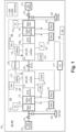
- FIG. 1 an illustrative view of an embodiment of a system in accordance with the disclosure is shown in Fig. 1 and is designated generally by reference character 100.
- a power system 100 for a vehicle 102 is disclosed.
- the vehicle 102 can be an evacuated tube vehicle, such as an evacuated tube electric train.
- the system 100 architecture provided herein can however be readily applied to other applications that experience pressure changes, such as aircraft, by one of ordinary skill in the art having the benefit of this disclosure without undue experimentation.
- the system 100 can include, one or more power distribution sources 104 and one or more batteries 122 configured to supply electrical power to one or more power districts 106, 206.
- One or more power conversion devices 108/208 110/210, 112/212 can be housed within a respective power district 106, 206.
- the one or more power conversion devices 108/208 110/210, 112/212 can include a power blade or similar device, which can be included in a rack 314 based system (e.g., such as shown in Fig. 2 ).
- the power district 106, 206 can be configured to allow for managing a draw by a respective one or more loads 116/216 within the respective power district 106/206.
- the one or more power conversion devices 108/208 110/210, 112/212 can be configured to receive electrical power from one or more of the one or more power distribution sources 104 or one or more of one or more batteries 122, convert the electrical power to a secondary form, and then deliver the converted electrical power to the one or more loads 116/216 within the respective power district 106, 206.
- a controller 117 having logic module 118, can be operatively connected to the one or more power districts 106/206, configured to control at least a load draw.
- the logic module 118 can include machine readable instructions configured to, at least, determine a system condition of the power system 100, prioritize each of the one or more loads 116/216 (e.g., within the respective districts, as well as across districts), and control power delivery from each of the one or more power districts 106/206 to the respective loads 116/216 based at least in part on the priority of the load. For example, each load within a district 106/206 may be given a predetermined priority for a given system condition.
- the logic module 118 is configured to control power delivery to each load in order of their priority given the determined system condition.
- certain loads may have a medium or high priority during normal operation, but may have a low priority during a system failure. During the normal operation, such loads would receive power first, over lower priority loads, based on a total power budget. The power is delivered to each load in order of priority until the budget runs out. But during a system failure, those medium to high priority loads may be reclassified as low priority loads, and will not receive power until the new high priority loads have received sufficient power and if there is still power left in the budget.
- the logic module 118 can be configured to prioritize respective load 116 and its allotted draw based on any one or more of the determined system condition (e.g., near total system failure, one power district failure, one power converter failure, and the like), a mission profile phase (e.g., start up, cruise, idle), and/or a budgeted designated current for each of the respective one or more loads.
- the determined system condition e.g., near total system failure, one power district failure, one power converter failure, and the like
- a mission profile phase e.g., start up, cruise, idle
- a budgeted designated current for each of the respective one or more loads.
- controller 117 While only a single local system controller 117 is shown, it is contemplated that in certain embodiments, any suitable number of controllers can be included, e.g., for redundancy. In certain applications, a single controller 117 for the vehicle is acceptable. In certain application, one or more controllers (e.g., the same or similar to controller 117) may be required to ensure the described systems are able to operate if a there is a controller failure. In such embodiments, the one or more redundant controllers can be arranged in any suitable manner to determine priority and address any conflicting commands between the controllers (e.g., the one or more controller can operate in a master/master, master/standby, majority voting, scheme, or the like).
- the one or more controller can operate in a master/master, master/standby, majority voting, scheme, or the like.
- the one or more power districts 106/206 include at least a first power district 106 and at least a second power district 206 are electrically coupled via a bus tie 120.
- the first power district can be represented by a first channel and the second power district can be represented by a second channel.
- the logic module 118 and the bus tie 120 can be operatively connected to each other and the respective first and second power districts 106/206 such that when the determined system condition includes a power failure in the first power district 106, the logic module 118 can be configured to control the bus tie 120 to serve as a cross tie such that the second power district 206 is configured to supply power to the first power district 106 during the power failure (e.g., with any available idle power blade in the second power district).
- the priority of the loads would be reclassified based on only on their priority within their respective power districts, but also across the first and second districts.
- a medium priority load in the second power district 206 may be reclassified as a low priority load, and its budgeted power allocation could be redirected to high priority loads in the first power district 106 as needed during the power failure.
- At least one of the one or more power conversion devices 108/208 110/210, 112/212 can include a DC/DC converter 108/208.
- the DC/DC converter 108/208 can be configured to receive high voltage DC power (e.g., at least about 350V), convert the high voltage DC power to low voltage DC power (e.g., about 28Vdc), and supply the low voltage DC power to the one or more loads 116/216 based on the priority scheme outlined above.
- the secondary form includes a lower voltage DC power than the high voltage received by the power converter 108/208.
- At least one of the loads 116/216 can include, an SSPC module, a lighting system, a lavatory, an infotainment system, a seating system, a galley, a communications module, and/or the like.
- At least one of the one or more power conversion devices 108/208 110/210, 112/212 can include a motor drive 110/210.
- the motor drive 110/210 can be configured to receive high voltage DC power (e.g., at least about 350V), convert the high voltage DC power to AC variable-voltage variable-frequency wave form, and supply the wave form to one or more of the one or more loads 116/216 based on the priority scheme outlined above.
- at least one load of the one or more loads 116/216 can include compressor motor drive of an environmental control system (ECS), or a vehicle traction drive control system.
- ECS environmental control system
- At least one of the one or more power conversion devices 108/208 110/210, 112/212 can include a traction drive 112/212.
- the traction drive 112/212 can be configured to receive high voltage DC power (e.g., at least about 350V), convert the high voltage DC power to AC variable-voltage variable-frequency wave form, and supply the wave form to one or more of the one or more loads.
- at least one load of the one or more loads can include an electric motor.
- SSPC power solid state power controller
- the SSPC module 113/213 can be operatively commanded to provide power or remove power to or from certain loads 116/216.
- the SSPC module 113/213 can be designed to detect failures, including but not limited to overcurrents, short circuits, and arcing faults, and remove power from failed loads or wires.
- the system 100 can include one or more batteries 122 operatively connected to a respective power district 106/206 via another bus 124 tie configured to supply electrical power to one or more loads (e.g., serving as a power distribution source) and/or configured to source the stored electrical power supplied to the respective power district 106/206.
- the power distribution source can include a hot shoe 104, if the vehicle includes a train traveling on electrified rail.
- the one or more batteries 122 can be charged by the hot shoe 104 or by one or more external, off board power sources.
- the power districts 106/206 can be supplied power from a fuel cell or turbogenerator or any other suitable power generator.
- the fuel cell, turbogenerator, or other generator can be configured to charge the batteries 122, which can then supply the power to the power districts 106/206.
- the controller 117 can be further configured to output power district data to a main vehicle controller 126 (e.g., a higher level main system controller).
- the power district data can include, for example, a status and health of the one or more power conversion devices 108/208 110/210, 112/212, a status and health of the one or more loads 116/216, a power status (e.g., DC power status) of the one or more loads 116/216, and/or an SSPC status for one or more connected loads 116/216 connected to a respective SSPC module 113/213.
- the controller 117 can be operatively connected to the high-level main vehicle controller 126 and configured to provide the power district data to the main vehicle controller 126 via a digital data bus 128.
- a modular power distribution architecture 400 can include a power district (e.g., districts 106/206) having a plurality of power converters (e.g., converters 108/208 110/210, 112/212) configured to power one or more loads (e.g., loads 116/216) within the power district.
- Each power converter can be sized to provide less than peak power to its respective load alone. For example, if the power district requires 100kW of power during peak, each individual power converter can be sized to provide less than 100kW of power alone.
- the architecture can include any one or all of the power converters 108/208 110/210, 112/212 and SSPC modules 113/213 discussed above connected in any suitable manner.
- the architecture 400 can include a DC/DC power converter 108/208, a motor drive 110/210, a traction drive 112/212, and an SSPC module 113/213.
- each of the DC/DC power converter, a motor drive, and a traction drive can include submodules connected in parallel.
- the DC/DC power converter can include at two DC/DC power converters connected in parallel.
- the combined total output of the two DC/DC power converters is sized to provide sufficient power to a first load type based on a mission profile load draw priority scheme for the first load type.
- each submodule can be sized for half of the power requirement for the first load type at the given mission phase.
- each submodule need not be equally sized.
- the first load type can include at least one of a lighting system, a lavatory, an infotainment system, and/or a seating system.
- each of the motor drive and traction drive can include at least two respective submodules connected in parallel, where the combined total output of the respective submodules is sized to provide sufficient power to a second load type based on the mission profile load draw priority scheme for a second load type and a third load type respectively.
- the second load type can include compressor motor drive for an environmental control system and the third load type can include traction control system.
- the power districts and conversion devices can be configured to the cluster of functionality that performs power conversion (e.g., including motor drive waveforms and standard ac/DC waveforms), and power distribution including functions like source selection and load management.
- the actual packaging of the various elements within the power districts may vary due to installation constraints, therefore the rack-based system shown in Fig. 2 may not be used for every application or vehicle.
- the motor controllers may be packaged with the DC/DC power converters
- the power distribution modules may be packaged with general purpose computing.
- Each power district can be fed by one-to-many primary power feeds depending upon the needs of the loads, for example.
- a one power district per rack is not required or desired, thus any suitable packaging arrangement is contemplated herein.
- Embodiments include a modular power conversion and control architecture. Embodiments allow for simple scalability, for example for higher power systems with parallelable commoditized power blades, or for smaller, lower power systems. Scalable systems can be more cost effective in certain applications such as rail. Embodiments can include highly integrated systems that provide high power density and efficiency, as well as more efficient use of resources (e.g. the power conversion blades, micro-controller blades, etc). For example, in embodiments certain power converter blades/modules can multiplex between applications, such as the ECS motor drive and the traction drive. In embodiments, it may not be necessary to provide power to both the motor drive and traction drive at the same time, so it may be more efficient to size the converters to provide less than peak power.
- the converter for both the motor drive and traction drive can provide a total combined output to supply peak power to the motor drive when needed.
- the same can be true for the traction drive.
- One having ordinary skill in the art in view of this disclosure would appreciate a base power needed to complement a multiplexed system for a given power requirement.
- Embodiments do not require highly specific, dedicated parts or specific wattage parts. Instead, embodiments can include the power districts as provided herein having one or more of the power conversion devices chosen and sized for a predetermined power requirement or for a given mission profile. This allows for the systems and architecture provided herein to be more cost effective and transferrable to many mission profiles, power requirements, or applications.
- Embodiments can include multiple modular and reconfigurable controllers for driving multiple different loads, embedded SiC power semiconductor and Si Solid State Power Controller (SSPC) technology for both high voltage and low voltage DC, multiplexing and protection capabilities, EMC and filtering, and health management of the controllers via re-configurability.
- SSPC Solid State Power Controller
- Embodiments provide for improved maintainability, repair, and replacement (e.g., it is physically easier to access motor drives if in a rack-based system such as described herein). Further, embodiments can reduce overall power system weight (e.g. about 40% weight reduction over traditional systems), can reduce costs (e.g., by including a common motor drive design for all motor-driven load types).
- Such embodiments can include a 350 to 28V DC/DC converter, a 350VDC to 3-phase/115VAC motor drive, and an SSPC (solid state power controller).
- the DC/DC converter can include modular, parallelable 3 to 5kW circuit cards.
- the motor controller e.g., for powering and control of ECS and traction control systems
- Embodiments can include 28Vdc SSPC's. Embodiments allow for standardized part numbers for each modular function and for long term optimization as a commoditized item for certain cost-sensitive applications. While specific voltages and power levels are provided herein for explanation, any suitable voltage and/or power levels may be used as needed or desired for a given application.
- aspects of the present disclosure may be embodied as a system, architecture, method, module, or product. Accordingly, aspects of this disclosure may take the form of an entirely hardware embodiment, an entirely software embodiment (including firmware, resident software, micro-code, etc.), or an embodiment combining software and hardware aspects, all possibilities of which can be referred to herein as a "circuit,” “module,” “controller,” or “system.”
- a “circuit,” “module,” “controller,” or “system” can include one or more portions of one or more separate physical hardware and/or software components that can together perform the disclosed function of the "circuit,” “module,” “controller,” or “system”, or a “circuit,” “controller,” “module,” or “system” can be a single self-contained unit (e.g., of hardware and/or software).
- aspects of this disclosure may take the form of a computer program product embodied in one or more computer readable medium(s) having computer readable program code embodied thereon.
- any numerical values disclosed herein can be exact values or can be values within a range. Further, any terms of approximation (e.g., “about”, “approximately”, “around”) used in this disclosure can mean the stated value within a range. For example, in certain embodiments, the range can be within (plus or minus) 20%, or within 10%, or within 5%, or within 2%, or within any other suitable percentage or number as appreciated by those having ordinary skill in the art (e.g., for known tolerance limits or error ranges).
- a reference to "A and/or B", when used in conjunction with open-ended language such as “comprising” can refer, in one embodiment, to A only (optionally including elements other than B); in another embodiment, to B only (optionally including elements other than A); in yet another embodiment, to both A and B (optionally including other elements); etc.
Landscapes
- Engineering & Computer Science (AREA)
- Power Engineering (AREA)
- Transportation (AREA)
- Mechanical Engineering (AREA)
- Life Sciences & Earth Sciences (AREA)
- Sustainable Development (AREA)
- Sustainable Energy (AREA)
- Chemical & Material Sciences (AREA)
- Combustion & Propulsion (AREA)
- Electric Propulsion And Braking For Vehicles (AREA)
- Charge And Discharge Circuits For Batteries Or The Like (AREA)
- Direct Current Feeding And Distribution (AREA)
Priority Applications (1)
| Application Number | Priority Date | Filing Date | Title |
|---|---|---|---|
| EP24191573.5A EP4429058A3 (fr) | 2022-08-15 | 2023-08-15 | Architecture de région de puissance pour un véhicule |
Applications Claiming Priority (1)
| Application Number | Priority Date | Filing Date | Title |
|---|---|---|---|
| US17/888,062 US12617298B2 (en) | 2022-08-15 | Power district architecture for a vehicle |
Related Child Applications (1)
| Application Number | Title | Priority Date | Filing Date |
|---|---|---|---|
| EP24191573.5A Division EP4429058A3 (fr) | 2022-08-15 | 2023-08-15 | Architecture de région de puissance pour un véhicule |
Publications (2)
| Publication Number | Publication Date |
|---|---|
| EP4325685A2 true EP4325685A2 (fr) | 2024-02-21 |
| EP4325685A3 EP4325685A3 (fr) | 2024-05-22 |
Family
ID=87575980
Family Applications (2)
| Application Number | Title | Priority Date | Filing Date |
|---|---|---|---|
| EP24191573.5A Pending EP4429058A3 (fr) | 2022-08-15 | 2023-08-15 | Architecture de région de puissance pour un véhicule |
| EP23191465.6A Pending EP4325685A3 (fr) | 2022-08-15 | 2023-08-15 | Architecture de région de puissance pour un véhicule |
Family Applications Before (1)
| Application Number | Title | Priority Date | Filing Date |
|---|---|---|---|
| EP24191573.5A Pending EP4429058A3 (fr) | 2022-08-15 | 2023-08-15 | Architecture de région de puissance pour un véhicule |
Country Status (1)
| Country | Link |
|---|---|
| EP (2) | EP4429058A3 (fr) |
Family Cites Families (2)
| Publication number | Priority date | Publication date | Assignee | Title |
|---|---|---|---|---|
| FR2902049B1 (fr) * | 2006-06-09 | 2008-09-05 | Alstom Transport Sa | Systeme et procede d'alimentation pour un vehicule ferroviaire, convertisseur, unite de pilotage, climatiseur pour ce systeme |
| CN110323734B (zh) * | 2018-03-29 | 2024-06-18 | 雅达电子国际有限公司 | 用于具有多个电源的电力系统的优先级负载分担 |
-
2023
- 2023-08-15 EP EP24191573.5A patent/EP4429058A3/fr active Pending
- 2023-08-15 EP EP23191465.6A patent/EP4325685A3/fr active Pending
Also Published As
| Publication number | Publication date |
|---|---|
| EP4429058A3 (fr) | 2025-02-19 |
| EP4325685A3 (fr) | 2024-05-22 |
| EP4429058A2 (fr) | 2024-09-11 |
| US20240051406A1 (en) | 2024-02-15 |
Similar Documents
| Publication | Publication Date | Title |
|---|---|---|
| JP5396670B2 (ja) | 電気的ネットワークの管理方法 | |
| US11312256B2 (en) | Multi-rotor aircraft comprising a system for propulsion and for non-propulsive electricity generation | |
| CN103415975B (zh) | 交通工具电力管理和分配 | |
| EP1921742A2 (fr) | Système de conversion d'alimentation extensible et modulaire pour avion | |
| US10079493B2 (en) | Parallel modular converter architecture | |
| US8723354B2 (en) | Electrical power control system for a vehicle | |
| US7923857B2 (en) | System and method for supplying power for actuators on board an aircraft | |
| CN102210094B (zh) | 用于配电的配电设备和用于配电的方法 | |
| EP2015420A2 (fr) | Procédé et architecture pour la réduction dans un câblage de véhicule | |
| CN104718104B (zh) | 用于轨道车辆的能量管理系统 | |
| US9647455B2 (en) | EMI filter systems and methods for parallel modular converters | |
| US8089170B2 (en) | High torque starter/generator with low input voltage | |
| US20200083717A1 (en) | System for distributing mixed dc and ac electrical power for supplying variable frequency loads and fixed frequency loads | |
| US20220302843A1 (en) | Auxiliary voltage supply for power converter and use thereof in vehicles | |
| EP4325685A2 (fr) | Architecture de région de puissance pour un véhicule | |
| US12617298B2 (en) | Power district architecture for a vehicle | |
| CN110663152B (zh) | 高度冗余的直流电压网络 | |
| CN107399439B (zh) | 具有多相发电机的电力供应系统和具有这种电力供应系统的航空器 | |
| US12397727B2 (en) | Power supply system, and moving object including power supply system | |
| US20230138615A1 (en) | Auxiliary voltage supply for power converter and use thereof in vehicles | |
| JP2025140653A (ja) | 電力供給システム、移動体及び電力供給システムの制御方法 | |
| US20180086435A1 (en) | Power supply apparatus for aerospace actuator | |
| CN115912485A (zh) | 全电飞行器的动力和机载电能系统及相关的电源系统 | |
| US20250162720A1 (en) | Aircraft power supply system and associated aircraft | |
| Saha et al. | Electrical System Architecture for Aviation Electrification |
Legal Events
| Date | Code | Title | Description |
|---|---|---|---|
| PUAI | Public reference made under article 153(3) epc to a published international application that has entered the european phase |
Free format text: ORIGINAL CODE: 0009012 |
|
| STAA | Information on the status of an ep patent application or granted ep patent |
Free format text: STATUS: THE APPLICATION HAS BEEN PUBLISHED |
|
| AK | Designated contracting states |
Kind code of ref document: A2 Designated state(s): AL AT BE BG CH CY CZ DE DK EE ES FI FR GB GR HR HU IE IS IT LI LT LU LV MC ME MK MT NL NO PL PT RO RS SE SI SK SM TR |
|
| RIC1 | Information provided on ipc code assigned before grant |
Ipc: H02J 3/14 20060101AFI20240129BHEP |
|
| PUAL | Search report despatched |
Free format text: ORIGINAL CODE: 0009013 |
|
| AK | Designated contracting states |
Kind code of ref document: A3 Designated state(s): AL AT BE BG CH CY CZ DE DK EE ES FI FR GB GR HR HU IE IS IT LI LT LU LV MC ME MK MT NL NO PL PT RO RS SE SI SK SM TR |
|
| RIC1 | Information provided on ipc code assigned before grant |
Ipc: H02J 3/14 20060101AFI20240417BHEP |
|
| STAA | Information on the status of an ep patent application or granted ep patent |
Free format text: STATUS: REQUEST FOR EXAMINATION WAS MADE |
|
| 17P | Request for examination filed |
Effective date: 20241122 |
|
| RBV | Designated contracting states (corrected) |
Designated state(s): AL AT BE BG CH CY CZ DE DK EE ES FI FR GB GR HR HU IE IS IT LI LT LU LV MC ME MK MT NL NO PL PT RO RS SE SI SK SM TR |