EP4325700A1 - Stator, moteur électrique et véhicule électrique - Google Patents
Stator, moteur électrique et véhicule électrique Download PDFInfo
- Publication number
- EP4325700A1 EP4325700A1 EP22803818.8A EP22803818A EP4325700A1 EP 4325700 A1 EP4325700 A1 EP 4325700A1 EP 22803818 A EP22803818 A EP 22803818A EP 4325700 A1 EP4325700 A1 EP 4325700A1
- Authority
- EP
- European Patent Office
- Prior art keywords
- iron core
- cooling channel
- oil
- slot
- stator
- Prior art date
- Legal status (The legal status is an assumption and is not a legal conclusion. Google has not performed a legal analysis and makes no representation as to the accuracy of the status listed.)
- Granted
Links
Images


Classifications
-
- H—ELECTRICITY
- H02—GENERATION; CONVERSION OR DISTRIBUTION OF ELECTRIC POWER
- H02K—DYNAMO-ELECTRIC MACHINES
- H02K5/00—Casings; Enclosures; Supports
- H02K5/04—Casings or enclosures characterised by the shape, form or construction thereof
- H02K5/20—Casings or enclosures characterised by the shape, form or construction thereof with channels or ducts for flow of cooling medium
- H02K5/203—Casings or enclosures characterised by the shape, form or construction thereof with channels or ducts for flow of cooling medium specially adapted for liquids, e.g. cooling jackets
-
- H—ELECTRICITY
- H02—GENERATION; CONVERSION OR DISTRIBUTION OF ELECTRIC POWER
- H02K—DYNAMO-ELECTRIC MACHINES
- H02K1/00—Details of the magnetic circuit
- H02K1/06—Details of the magnetic circuit characterised by the shape, form or construction
- H02K1/12—Stationary parts of the magnetic circuit
- H02K1/20—Stationary parts of the magnetic circuit with channels or ducts for flow of cooling medium
-
- H—ELECTRICITY
- H02—GENERATION; CONVERSION OR DISTRIBUTION OF ELECTRIC POWER
- H02K—DYNAMO-ELECTRIC MACHINES
- H02K3/00—Details of windings
- H02K3/04—Windings characterised by the conductor shape, form or construction, e.g. with bar conductors
- H02K3/24—Windings characterised by the conductor shape, form or construction, e.g. with bar conductors with channels or ducts for cooling medium between the conductors
-
- H—ELECTRICITY
- H02—GENERATION; CONVERSION OR DISTRIBUTION OF ELECTRIC POWER
- H02K—DYNAMO-ELECTRIC MACHINES
- H02K5/00—Casings; Enclosures; Supports
- H02K5/04—Casings or enclosures characterised by the shape, form or construction thereof
- H02K5/15—Mounting arrangements for bearing-shields or end plates
-
- H—ELECTRICITY
- H02—GENERATION; CONVERSION OR DISTRIBUTION OF ELECTRIC POWER
- H02K—DYNAMO-ELECTRIC MACHINES
- H02K9/00—Arrangements for cooling or ventilating
- H02K9/19—Arrangements for cooling or ventilating for machines with closed casing and closed-circuit cooling using a liquid cooling medium, e.g. oil
-
- B—PERFORMING OPERATIONS; TRANSPORTING
- B60—VEHICLES IN GENERAL
- B60K—ARRANGEMENT OR MOUNTING OF PROPULSION UNITS OR OF TRANSMISSIONS IN VEHICLES; ARRANGEMENT OR MOUNTING OF PLURAL DIVERSE PRIME-MOVERS IN VEHICLES; AUXILIARY DRIVES FOR VEHICLES; INSTRUMENTATION OR DASHBOARDS FOR VEHICLES; ARRANGEMENTS IN CONNECTION WITH COOLING, AIR INTAKE, GAS EXHAUST OR FUEL SUPPLY OF PROPULSION UNITS IN VEHICLES
- B60K1/00—Arrangement or mounting of electrical propulsion units
- B60K2001/003—Arrangement or mounting of electrical propulsion units with means for cooling the electrical propulsion units
- B60K2001/006—Arrangement or mounting of electrical propulsion units with means for cooling the electrical propulsion units the electric motors
-
- Y—GENERAL TAGGING OF NEW TECHNOLOGICAL DEVELOPMENTS; GENERAL TAGGING OF CROSS-SECTIONAL TECHNOLOGIES SPANNING OVER SEVERAL SECTIONS OF THE IPC; TECHNICAL SUBJECTS COVERED BY FORMER USPC CROSS-REFERENCE ART COLLECTIONS [XRACs] AND DIGESTS
- Y02—TECHNOLOGIES OR APPLICATIONS FOR MITIGATION OR ADAPTATION AGAINST CLIMATE CHANGE
- Y02T—CLIMATE CHANGE MITIGATION TECHNOLOGIES RELATED TO TRANSPORTATION
- Y02T10/00—Road transport of goods or passengers
- Y02T10/60—Other road transportation technologies with climate change mitigation effect
- Y02T10/64—Electric machine technologies in electromobility
Definitions
- This application relates to the field of motor technologies, and in particular, to a stator, a motor, and an electric vehicle.
- a motor in a powertrain of an electric vehicle includes a rotor and a stator.
- a cooling manner is to dispose a slot at a root of a corresponding stator tooth to guide oil, and another cooling manner is to insert a cooling pipe into the stator.
- the first cooling manner there is only one layer of cooling channel, and a cooling capability is insufficient, and consequently it is difficult to cope with increasingly high power density of the motor.
- This application provides a stator, a motor, and an electric vehicle, to provide a stator with a high heat dissipation capability to meet an increasingly high power density requirement of a motor.
- this application provides a stator.
- the stator includes a housing, an iron core punching sheet, a spacer sleeve, and a flow guiding assembly.
- the iron core punching sheet is sleeved in an accommodation cavity of the housing, and an outer edge of the iron core punching sheet abuts against an inner wall of the housing.
- the iron core punching sheet includes a yoke part and a plurality of tooth parts, the plurality of tooth parts are evenly distributed on an inner side of the yoke part in a circumferential direction, and a stator slot is disposed between adjacent tooth parts.
- a first cooling channel is disposed between an outer edge of the yoke part and the housing.
- the first cooling channel may cool an outer surface of the iron core punching sheet.
- a second cooling channel is disposed on an inner edge of the yoke part, and the second cooling channel is located between adjacent tooth parts.
- the second cooling channel may cool a root of the stator slot.
- the spacer sleeve is sleeved in the iron core punching sheet, and an outer surface of the spacer sleeve abuts against a side that is of the tooth part and that faces away from the yoke part.
- a slot opening of the stator slot between the adjacent tooth parts fits with the spacer sleeve to form a third cooling channel.
- the third cooling channel may cool a slot opening position of the stator slot.
- the flow guiding assembly is disposed in the accommodation cavity, communicates with the first cooling channel, the second cooling channel, and the third cooling channel, and may guide, in a direction from the first cooling channel to the second cooling channel and then to the third cooling channel, coolant oil flowing out of an oil inlet.
- the coolant oil may flow in the direction from the first cooling channel to the second cooling channel and then to the third cooling channel.
- the coolant oil first flows through the first cooling channel between the iron core punching sheet and the housing, and the coolant oil in the first cooling channel preliminarily cools the stator.
- the coolant oil enters the second cooling channel, and the coolant oil in the second cooling channel cools the stator again.
- the coolant oil enters the third cooling channel, and the coolant oil in the third cooling channel cools the stator for a third time.
- the three-layer oil-injection cooling design can increase a contact area between the coolant oil and the stator, to improve a heat dissipation capability of the stator provided in this application, so as to meet a cooling requirement, in a low-speed and high-torque working condition and a high-rotation-speed working condition, of a motor to which the stator is applied.
- a position of the oil inlet on the housing When a position of the oil inlet on the housing is set, it may be set that in an extension direction of the housing, the oil inlet is located on a side part of the housing, and the oil inlet is located between end faces on two sides of the iron core punching sheet. It should be understood that after the coolant oil enters the accommodation cavity, the coolant oil may flow from the position of the oil inlet to two sides along the first cooling channel. That is, after a winding is installed, coolant oil on one side of the winding has two flow directions, to improve a cooling effect.
- the first cooling channel includes the housing and/or the iron core punching sheet.
- the first cooling channel includes a hole disposed on a side wall of the housing.
- the first cooling channel includes a hole formed through fitting between a side wall of the housing and the iron core punching sheet.
- the first cooling channel includes a hole on the iron core punching sheet.
- the first cooling channel includes only the iron core punching sheet
- the first cooling channel includes a plurality of first oil guiding slots disposed on the outer edge of the yoke part, and each first oil guiding slot penetrates through the iron core punching sheet in an extension direction of the iron core punching sheet.
- each first oil guiding slot corresponds to one stator slot, so that the first oil guiding slot has a better cooling effect.
- the first oil guiding slot does not correspond to the stator slot. Details are not described herein.
- the second cooling channel includes a plurality of second oil guiding slots disposed on the inner edge of the yoke part, and each second oil guiding slot penetrates through the iron core punching sheet in the extension direction of the iron core punching sheet.
- Each second oil guiding slot corresponds to one stator slot, so that the second oil guiding slot has a better cooling effect. It should be understood that each second oil guiding slot is disposed at a position that avoids the tooth part, to ensure electromagnetic performance of the stator provided in this application.
- each first oil guiding slot and/or the second oil guiding slot are/is an open slot or a through hole formed on the yoke part.
- each first oil guiding slot may be an open slot whose opening is located on an outer surface of the yoke part or a through hole formed on the yoke part
- each second oil guiding slot may be an open slot whose opening is located on an inner surface of the yoke part or a through hole formed on the yoke part.
- each first oil guiding slot is a through hole formed on the yoke part, that is, each first oil guiding slot forms an independent oil guiding path; and each second oil guiding slot may be an open slot whose opening is located on the inner surface of the yoke part, and a winding wound in the stator slot is in direct contact with the coolant oil, to implement a better cooling effect.
- the iron core punching sheet includes two iron core punching sub-sheets
- the flow guiding assembly includes two end plates and a ring-shaped intermediate flow guiding member.
- the intermediate flow guiding member is made of a same material as the iron core punching sheet. In other words, the intermediate flow guiding member is an iron core punching sheet in another shape.
- the two end plates are disposed opposite to each other, each end plate abuts against one end of the iron core punching sheet, a flow guiding slot is disposed on a side that is of each end plate and that faces the iron core punching sheet, and the flow guiding slot communicates with the first cooling channel and the second cooling channel, to guide the coolant oil from the first cooling channel to the second cooling channel.
- the intermediate flow guiding member abuts between the two iron core punching sub-sheets, and corresponds to the position of the oil inlet.
- an outer edge of the ring-shaped intermediate flow guiding member cannot block the first cooling channel, so that the coolant oil can enter the first cooling channel from the oil inlet, and an inner edge of the intermediate flow guiding member cannot block the second cooling channel, so that the coolant oil can be guided to the third cooling channel from the second cooling channel.
- each first oil guiding slot and each second oil guiding slot are through holes formed on the yoke part, that is, each first oil guiding slot and each second oil guiding slot form an independent oil guiding path.
- each second oil guiding slot forms an independent oil guiding channel, and therefore the coolant oil is not in direct contact with a winding wound in the stator slot, and a coil in the winding is prevented from entering the cooling channel in a process. In this way, the process is simpler, and implementation costs are lower.
- another structure in the second possible implementation is the same as the structure in the first possible implementation.
- each first oil guiding slot is an open slot whose opening is located on the outer surface of the yoke part, and the coolant oil may enter the first cooling channel through openings of some first oil guiding slots, to increase a speed at which the coolant oil enters the first cooling channel.
- each second oil guiding slot is a through hole formed on the yoke part, and the coolant oil is not in direct contact with a winding wound in the stator slot, and a coil is prevented from entering the cooling channel in a process. In this way, the process is simpler, and implementation costs are lower.
- another structure in the third possible implementation is the same as the structure in the first possible implementation and the structure in the second possible implementation.
- each first oil guiding slot is an open slot whose opening is located on the outer surface of the yoke part, and the coolant oil may enter the first cooling channel through openings of some first flow guiding slots, to increase a speed at which the coolant oil enters the first cooling channel.
- each second oil guiding slot is an open slot whose opening is located on the inner surface of the yoke part, and a winding wound in the stator slot is in direct contact with the coolant oil, to implement a better cooling effect.
- each first oil guiding slot is an open slot whose opening is located on the outer surface of the yoke part
- each second oil guiding slot is an open slot whose opening is located on the inner surface of the yoke part.
- the flow guiding assembly includes a first end plate and a second end plate that are disposed opposite to each other, and each of the first end plate and the second end plate abuts against one side of the iron core punching sheet. It should be noted that in the fourth possible implementation, only one type of iron core punching sheet needs to be disposed in the stator, and a structure design is simpler.
- each end plate includes a ring-shaped main body part and a plurality of extension parts.
- the main body part corresponds to the yoke part of the iron core punching sheet, and a plurality of abutting blocks are disposed on a side that is of the main body part and that faces the iron core punching sheet.
- the plurality of abutting blocks are evenly distributed on an outer side of the main body part in the circumferential direction, to form a flow guiding space between the end plate and the iron core punching sheet. It should be noted that each abutting block abuts against a part that is of the iron core punching sheet and that is located between adjacent first oil guiding slots.
- the plurality of extension parts are evenly distributed on an inner side of the main body part in the circumferential direction. There is a notch between adjacent extension parts, and a plurality of notches are formed by using the plurality of extension parts.
- Each of the plurality of notches corresponds to one stator slot, and the plurality of notches specifically include a first notch and a second notch that are alternately arranged in the circumferential direction.
- a separation structure is further disposed on a side that is of each end plate and that faces the iron core punching sheet.
- the separation structure surrounds the first notch, to separate the flow guiding space into a first flow guiding space and a second flow guiding space.
- the first notch is located in the second flow guiding space.
- the first flow guiding space corresponds to the first cooling channel
- the second flow guiding space corresponds to the second cooling channel.
- the first flow guiding space in each of the first end plate and the second end plate communicates with a second flow guiding space in the other end plate through the second flow guiding slot.
- the coolant oil flowing out of the first cooling channel may enter the first flow guiding space separated by the separation structure. Then, the coolant oil may enter, from the first flow guiding space on the side, the second cooling channel that communicates with the first flow guiding space. After the coolant oil flows from one end of the second cooling channel to the other end, the coolant oil may flow to the second flow guiding space between the end plate on the other side and the iron core punching sheet. Then, the coolant oil flows in the second flow guiding space. When the coolant oil flows in the second flow guiding space, the coolant oil may flow in an extension direction of the extension part.
- each of the first notch and the second notch corresponds to one stator slot, and each second flow guiding space surrounds one first notch. Therefore, when the coolant oil flows in the second flow guiding space, the coolant oil may reach the third cooling channel formed through fitting between the slot opening of the stator slot between the adjacent tooth parts and the spacer sleeve. Then, the coolant oil flows to two sides along the third cooling channel.
- the three-layer oil-injection cooling design can increase a contact area between the coolant oil and the stator, to improve a heat dissipation capability of the stator provided in this application, so as to meet a cooling requirement, in a low-speed and high-torque working condition and a high-rotation-speed working condition, of a motor to which the stator is applied.
- a plurality of separation structures may be formed. Specifically, there are at least the following several separation structures.
- Manner 1 It may be set that the separation structure includes a first separation substructure and a second separation substructure.
- the first separation substructure is connected to an end that is of extension parts on two sides of the first notch and that faces away from the main body part, the first separation substructure is partially located on the main body part, and there is a spacing between a part that is of the first separation substructure and that is located on the main body part and an inner edge of the main body part, to form an independent second flow guiding space.
- the second separation substructure is disposed on the inner edge of the main body part, and is connected to the adjacent first separation substructure, to form the first flow guiding space between an outer edge of the main body part and each of the first separation substructure and the second separation substructure.
- the separation structure includes a first separation substructure.
- the first separation substructure is connected to an end that is of extension parts on two sides of the first notch and that faces away from the main body part, and the first separation substructure is partially located on the main body part, to form an independent second flow guiding space.
- a fastening assembly may be further disposed.
- the disposed fastening assembly includes two fasteners disposed opposite to each other, each fastener corresponds to one end plate, and each fastener is disposed on a side that is of the end plate corresponding to the fastener and that faces away from the other end plate.
- an inner ring of each fastener is disposed on a barrier block configured to prevent the spacer sleeve from moving in an extension direction.
- this application further provides a motor.
- the motor includes a rotor and any stator provided in the technical solution in the first aspect. It should be understood that the rotor fits with the stator to perform a function.
- coolant oil may flow in a direction from a first cooling channel to a second cooling channel and then to a third cooling channel.
- the coolant oil first flows through the first cooling channel on an outer surface of an iron core punching sheet, and the coolant oil in the first cooling channel preliminarily cools the stator.
- the coolant oil enters the second cooling channel, and the coolant oil in the second cooling channel cools the stator again.
- the coolant oil enters the third cooling channel, and the coolant oil in the third cooling channel cools the stator for a third time.
- the three-layer oil-injection cooling design can increase a contact area between the coolant oil and the stator, to improve a heat dissipation capability of the stator provided in this application, so as to meet a cooling requirement, in a low-speed and high-torque working condition and a high-rotation-speed working condition, of the motor to which the stator is applied.
- this application further provides an electric vehicle, and any motor provided in the technical solution in the second aspect is installed in the electric vehicle.
- the motor in the electric vehicle is in line with a trend of a high speed and miniaturization of the motor.
- the stator provided in embodiments of this application may be applied to a motor in an electric vehicle.
- the motor is used as a core of a power output of the electric vehicle, and a key point in design of the motor is to ensure normal and stable running.
- a heat loss of the motor should be considered.
- the heat loss of the motor includes a coil loss, an iron core loss, a frictional loss, a stray loss, and a mechanical loss.
- the coil loss is caused due to heat generation caused by ohmic resistance and a skin effect, and the iron core loss mainly comes from an eddy current loss.
- FIG. 1 is a diagram of a relationship between a rotation speed and torque of a motor.
- g1 represents the coil loss
- g2 represents the iron core loss.
- the coil loss increases with the torque
- the iron core loss increases with the rotation speed.
- FIG. 2 is a diagram of a structure of an iron core punching sheet 01 in a stator in the conventional technology.
- an oil guiding slot 012 is disposed at a position, on the iron core punching sheet 01, corresponding to each tooth part 011. Coolant oil is input to the oil guiding slot 012, to cool the iron core punching sheet 01.
- FIG. 3 is a diagram of a structure of another stator 001 in the conventional technology.
- the stator 001 includes an iron core punching sheet 01 and a cooling pipe 02
- the cooling pipe 02 includes a first side pipe 021 and a second side pipe 022. It should be noted that the first side pipe 021 and the second side pipe 022 penetrate through the iron core punching sheet 01, to cool the iron core punching sheet 01.
- FIG. 4 is an enlarged schematic diagram of the cooling pipe 02 in FIG. 3 .
- double-layer cooling of the structure of the stator 001 is implemented by using the cooling pipe 02 in the structure of the stator shown in FIG. 3 , but it is still difficult to cope with increasingly high power density of a motor, and in the cooling manner, a structure is complex, resulting in a complex manufacturing process and high costs.
- embodiments of this application provide a stator, to provide a stator with a high heat dissipation capability to meet an increasingly high power density requirement of a motor.
- FIG. 5 is a schematic diagram of a structure of a stator 100 according to an embodiment of this application.
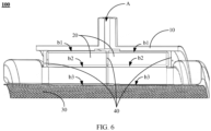
- FIG. 6 is a sectional view on a plane M in FIG. 5 .
- a housing 10 has an accommodation cavity, and an oil inlet A is disposed on the housing 10.
- coolant oil may be input from outside to the accommodation cavity, to cool the stator 100 provided in this embodiment of this application.
- an iron core punching sheet 20 for implementing an electromagnetic function of the stator 100, a spacer sleeve 30 sleeved in the iron core punching sheet 20, and a flow guiding assembly 40 that performs a flow guiding function are installed in the accommodation cavity.
- the iron core punching sheet 20 abuts against an inner wall of the housing 10.
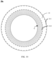
- a structure of the iron core punching sheet 20 is a ring-shaped structure shown in FIG. 7 , and the iron core punching sheet 20 includes a yoke part 21 and a plurality of tooth parts 22.
- the plurality of tooth parts 22 are evenly distributed on an inner side of the yoke part 21 in a circumferential direction, and a stator slot C is disposed between adjacent tooth parts 22.
- a winding that includes a coil is wound in the stator slot C. It should be understood that to clearly show a position relationship among the iron core punching sheet 20, the spacer sleeve 30, and the flow guiding assembly 40, the winding is not shown herein.
- a first cooling channel b1 is disposed between an outer edge of the yoke part 21 of the iron core punching sheet 20 and the housing 10, and the first cooling channel b1 communicates with the oil inlet A.
- the coolant oil may cool an outer surface of the iron core punching sheet 20.
- a second cooling channel b2 is disposed on an inner edge of the yoke part 21 of the iron core punching sheet 20.
- the coolant oil may cool a root of the stator slot C.
- a slot opening of the stator slot C fits with the spacer sleeve 30 to form a third cooling channel b3 shown in FIG. 6 .
- the coolant oil flows in the third cooling channel b3
- the coolant oil cools a slot opening position of the stator slot C.
- the three-layer oil-injection cooling design can increase a contact area between the coolant oil and the stator 100, to improve a heat dissipation capability of the stator 100 provided in this application.
- FIG. 8 is a schematic diagram of flow of coolant oil in the stator 100 shown in FIG. 6 .
- a flow direction of the coolant oil in the stator 100 is shown by an arrow direction in FIG. 8 .
- the flow guiding assembly 40 guides the coolant oil to flow in a direction from the first cooling channel b1 to the second cooling channel b2 and then to the third cooling channel b3.
- the coolant oil In a process in which the coolant oil flows in the direction, the coolant oil first flows through the first cooling channel b1 on the outer surface of the iron core punching sheet 20, and the coolant oil in the first cooling channel b1 preliminarily cools the stator 100. Then, the coolant oil enters the second cooling channel b2, and the coolant oil in the second cooling channel b2 cools the stator 100 again. Finally, the coolant oil enters the third cooling channel b3, and the coolant oil in the third cooling channel b3 cools the stator 100 for a third time.
- the first cooling channel b1 includes the housing 10 and/or the iron core punching sheet 20.
- the first cooling channel b1 includes a hole disposed on a side wall of the housing 10.
- the first cooling channel b1 includes a hole formed through fitting between a side wall of the housing 10 and the iron core punching sheet 20.
- the first cooling channel b1 includes a hole on the iron core punching sheet 20.
- the first cooling channel b1 shown in FIG. 6 may include a plurality of first oil guiding slots 211 disposed on the outer edge of the yoke part 21 shown in FIG. 7 .
- the second cooling channel b2 shown in FIG. 6 may include a plurality of second oil guiding slots 212 disposed on the inner edge of the yoke part 21 shown in FIG. 7 .
- each first oil guiding slot 211 penetrates through the iron core punching sheet 20 in an extension direction of the iron core punching sheet 20
- each second oil guiding slot 212 penetrates through the iron core punching sheet 20 in the extension direction of the iron core punching sheet 20.
- each first oil guiding slot 211 corresponds to one stator slot C, so that the first oil guiding slot 211 better cools the stator 100.
- each second oil guiding slot 212 corresponds to one stator slot C, so that the second oil guiding slot 212 better cools the stator 100 and the winding.
- the second oil guiding slot 212 is disposed between adjacent tooth parts 22, and avoids a root region of the tooth part 22, to ensure electromagnetic performance of the stator 100.
- first oil guiding slot 211 when the position of the first oil guiding slot 211 is set, there may be no correspondence between the first oil guiding slot 211 and the stator slot C. This is not limited herein.
- shapes of the first oil guiding slot 211 and the second oil guiding slot 212 are not limited to the structure shown in FIG. 7 , and may be changed based on a use requirement. Details are not described herein.
- the oil inlet A is located between end faces on two sides of the iron core punching sheet 20. It should be understood that after the coolant oil enters the accommodation cavity, the coolant oil may flow from a position of the oil inlet A to two sides along the first cooling channel b1, to improve a cooling effect. Certainly, the position at which the oil inlet A is disposed may be offset in the direction d relative to a position in FIG. 8 based on a requirement. Details are not described herein.
- each first oil guiding slot 211 and the second oil guiding slot 212 may be set that the first oil guiding slot 211 and/or the second oil guiding slot 212 are/is an open slot or a through hole.
- each first oil guiding slot 211 may be an open slot whose opening is located on an outer surface of the yoke part 21
- each second oil guiding slot 212 may be an open slot whose opening is located on an inner surface of the yoke part 21.
- different structures are set for the iron core punching sheet 20 and the flow guiding assembly 40, to correspond to different structures of the first oil guiding slot 211 and the second oil guiding slot 212. Specifically, there are at least the following several implementations.
- FIG. 9 is a sectional view of the stator 100 according to the implementation 1.
- the iron core punching sheet is shown in a form of two iron core punching sub-sheets 20a.
- the iron core punching sheet in the implementation 1 includes two iron core punching sub-sheets 20a.
- the flow guiding assembly 40 includes two end plates 41 and an intermediate flow guiding member 42. The intermediate flow guiding member 42 abuts between the two iron core punching sub-sheets 20a.
- each end plate 41 As for positions at which the two end plates 41 are disposed, still referring to the structure shown in FIG. 9 , the two end plates 41 are disposed opposite to each other, each end plate 41 abuts against an end that is of one iron core punching sub-sheet 20a and that faces away from the other iron core punching sub-sheet 20a, and a flow guiding slot (namely, a concave slot at a cross section of the end plate 41 shown in FIG. 8 ) is disposed on a side that is of each end plate 41 and that faces the iron core punching sub-sheet 20a corresponding to the end plate 41.
- a flow guiding slot namely, a concave slot at a cross section of the end plate 41 shown in FIG. 8
- the flow guiding slot communicates with the first cooling channel b1 and the second cooling channel b2, to guide the coolant oil from the first cooling channel b1 to the second cooling channel b2. It should be noted that in a flow guiding process of the end plate 41, the flow guiding slot distributes the coolant oil, so that a part or all of the coolant oil flows to the second cooling path b2.
- An end plate 41 in FIG. 9 is used as an example.
- a small hole is formed on the end plate 41, and the small hole communicates with the flow guiding slot, to guide a part of the coolant oil in the flow guiding slot to a side that is of the end plate 41 and that faces away from the iron core punching sub-sheet 20a.
- the small hole on the end plate 41 may be disposed based on a requirement. Details are not described herein.
- each first oil guiding slot 211 disposed on the yoke part 21 is a through hole, and each first oil guiding slot 211 forms an independent oil guiding path.
- each second oil guiding slot 212 disposed on the yoke part 21 is an open slot whose opening is located on the inner surface of the yoke part 21.
- each second oil guiding slot 212 communicates with a stator slot C that is in a one-to-one correspondence with the second oil guiding slot 212. Therefore, a winding wound in the stator slot C is in direct contact with the coolant oil in the second oil guiding slot 212, to implement a better cooling effect.
- insulation paper is placed between the stator slot C and the winding.
- the winding is in direct contact with the coolant oil in the second oil guiding slot 212 herein means that the winding is separated from the coolant oil in the second oil guiding slot 212 by only one layer of insulation paper.
- the insulation paper is thin. Therefore, it may be considered that only thermal-convection resistance exists between the coolant oil in the second oil guiding slot 212 and the winding, and therefore the coolant oil has a better cooling effect on the winding.
- FIG. 11 shows a specific structure of the intermediate flow guiding member 42.
- the intermediate flow guiding member 42 is of a ring-shaped structure.
- the intermediate flow guiding member 42 may be made of a same material as the iron core punching sub-sheet 20a.
- the intermediate flow guiding member 42 is an iron core punching sub-sheet 20a in another shape.
- an outer edge of the intermediate flow guiding member 42 does not go beyond a slot bottom of the first oil guiding slot 211, to guide the coolant oil to the first cooling channel.
- an inner edge of the intermediate flow guiding member 42 does not go beyond an outer edge of the second oil guiding slot 212, to guide the coolant oil from the second cooling channel b2 to a gap between the two iron core punching sub-sheets 20a.
- the outer edge of the intermediate flow guiding member 42 partially blocks the first oil guiding slot 211, and/or the inner edge of the intermediate flow guiding member 42 partially blocks the second oil guiding slot 212. Details are not described herein.
- FIG. 12 A specific flow manner of the coolant oil in the stator 100 provided in this application is shown in FIG. 12 .
- the coolant oil first reaches the housing 10, the outer edge of the intermediate flow guiding member 42, and a space formed between the two iron core punching sub-sheets 20a. Then, the coolant oil enters the first cooling channel b1 between the iron core punching sub-sheets 20a located on two sides of the intermediate flow guiding member 42. Then, the coolant oil flows along the first cooling channel b1 in a direction far away from the intermediate flow guiding member 42, until the coolant oil reaches the flow guiding slot formed between the end plate 41 and the iron core punching sub-sheet 20a.
- the coolant oil enters, along the flow guiding slot, the second cooling channel b2 that communicates with the flow guiding slot. Then, the coolant oil flows along the second cooling channel b2 in a direction close to the intermediate flow guiding member 42, until the coolant oil flows from the second cooling channel b2 to the gap between the two iron core punching sub-sheets 20a. After the coolant oil enters the gap between the two iron core punching sub-sheets 20a, the coolant oil flows in a direction from an outer side to an inner side of the iron core punching sub-sheet 20a, until the coolant oil reaches the third cooling channel b3 formed through fitting between the spacer sleeve 30 and the iron core punching sub-sheet 20a. Then, the coolant oil flows along the third cooling channel b3 to two sides.
- the three-layer oil-injection cooling design can increase a contact area between the coolant oil and the stator 100, to improve a heat dissipation capability of the stator 100 provided in this application.
- FIG. 14, FIG. 15 , FIG. 16, and FIG. 17 are all sectional views on a plane N in FIG. 13 .
- FIG. 14 shows a structure in which coolant oil is injected only into the stator slot C. Specifically, in the structure shown in FIG. 14 , two windings 50 are disposed in the stator slot C of the iron core punching sub-sheet 20a, and a cooling channel b is formed between the two windings 50. Heat in each winding 50 is transferred to the cooling channel b in a direction of a dashed line arrow in FIG. 14 for heat dissipation, and each part in the iron core punching sub-sheet 20a is transferred to the cooling channel in a direction of a solid line arrow in FIG. 14 for heat dissipation.
- FIG. 15 shows a structure in which coolant oil is injected only into a bottom of the stator slot C.
- a winding 50 is disposed in the stator slot C of the iron core punching sub-sheet 20a, and a cooling channel b is formed between the winding 50 and the iron core punching sub-sheet 20a.
- Heat in the winding 50 is transferred to the cooling channel b in a direction of a dashed line arrow in FIG. 15 for heat dissipation, and each part in the iron core punching sub-sheet 20a is transferred to the cooling channel in a direction of a solid line arrow in FIG. 15 for heat dissipation.
- FIG. 16 shows a structure in which coolant oil is injected only into a bottom of the stator slot C and an outer edge of the iron core punching sub-sheet 20a.
- a winding 50 is disposed in the stator slot C of the iron core punching sub-sheet 20a
- a cooling channel b is formed between the winding 50 and the iron core punching sub-sheet 20a
- another cooling channel b' is formed on the outer edge of the iron core punching sub-sheet 20a.
- Heat in the winding 50 is transferred to the cooling channel b in a direction of a dashed line arrow in FIG. 16 for heat dissipation
- each part in the iron core punching sub-sheet 20a is transferred to the cooling channel in a direction of a solid line arrow in FIG. 16 for heat dissipation.
- FIG. 17 shows a structure in which the three-layer oil-injection design in this implementation of this application is used.
- a first cooling channel b1, a second cooling channel b2, and a third cooling channel b3 are disposed on the iron core punching sub-sheet 20a.
- Heat in the winding 50 is transferred to each cooling channel in a direction of a dashed line arrow in FIG. 17 for heat dissipation, and each part in the iron core punching sub-sheet 20a is transferred to each cooling channel in a direction of a solid line arrow in FIG. 17 for heat dissipation.
- the three-layer oil-injection cooling design provided in this embodiment of this application can increase a contact area between the coolant oil and the stator 100, to improve a heat dissipation capability of the stator 100 provided in this application.
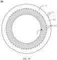
- FIG. 18 is a schematic diagram of a structure of an iron core punching sub-sheet 20a according to the implementation 2 of this application.
- each first oil guiding slot 211 is an open slot whose opening is located on the outer surface of the yoke part 21.
- many concave slots 213 in a shape different from that of the first oil guiding slot 211 are formed on the outer surface of the yoke part 21.
- the concave slot 213 is used as a welding slot during a welding operation, to connect a plurality of iron core punching sub-sheets 20a through welding.
- a structure of the housing 10 may be slightly deformed.
- a ring-shaped accommodation slot that faces the iron core punching sub-sheet 20a may be formed on a part that is of the housing 10 and that corresponds to the oil inlet A. After the coolant oil enters the accommodation cavity from the oil inlet A, the coolant oil may directly enter the first oil guiding slot 211 that communicates with the ring-shaped accommodation slot from the ring-shaped accommodation slot.
- the ring-shaped accommodation slot fits with the first oil guiding slot 211 to accelerate a speed of distributing the coolant oil from the oil inlet A to the first cooling channel b 1.
- the intermediate flow guiding member 42 in the implementation 2 may be thinner than the intermediate flow guiding member 42 in the implementation 1, to reduce manufacturing costs.
- FIG. 20 is a schematic diagram of a structure of an iron core punching sub-sheet 20a according to the implementation 3 of this application.
- each first oil guiding slot 211 and each second oil guiding slot 212 are through holes, that is, each first oil guiding slot 211 and each second oil guiding slot 212 form an independent oil guiding path.
- each second oil guiding slot 212 forms an independent oil guiding channel, and therefore the coolant oil is not in direct contact with the winding wound in the stator slot C, and a coil in the winding can be prevented from entering the cooling channel in a process. In this way, not only the process can be simplified, but also costs can be reduced.
- the first oil guiding slot 211 is an open slot whose opening is located on the outer surface of the yoke part 21, and each second oil guiding slot 212 is a through hole.
- the structure in the implementation 4 is a combination of the structure in the implementation 3 and the structure in the implementation 2, and therefore is not shown in a form of a figure herein.
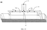
- FIG. 21 is a sectional view of the stator 100 according to the implementation 5.
- the stator 100 provided in the implementation 5 of this application includes only one type of iron core punching sheet 20, and a structural design is simpler.
- Structural designs of the first oil guiding slot 211 and the second oil guiding slot 212 on the iron core punching sheet 20 are the same as those of the first oil guiding slot 211 and the second oil guiding slot 212 on the iron core punching sub-sheet 20a shown in the implementation 2 in FIG. 21 .
- FIG. 21 is a sectional view of the stator 100 according to the implementation 5.
- the stator 100 provided in the implementation 5 of this application includes only one type of iron core punching sheet 20, and a structural design is simpler.
- Structural designs of the first oil guiding slot 211 and the second oil guiding slot 212 on the iron core punching sheet 20 are the same as those of the first oil guiding slot 211 and the second oil guiding slot 212 on the iron core punching sub-sheet 20a shown in the
- each first oil guiding slot 211 is an open slot whose opening is located on the outer surface of the yoke part 21, and each second oil guiding slot 212 is an open slot whose opening is located on the inner surface of the yoke part 21.
- the flow guiding assembly 40 includes a first end plate 40a and a second end plate 40b that are disposed opposite to each other, and each of the first end plate 40a and the second end plate 40b abuts against one side of the iron core punching sheet 20.
- the first end plate 40a is the same as that of the second end plate 40b.
- the structure of the first end plate 40a is used as an example to describe the structure of the end plate.
- the first end plate 40a includes a ring-shaped main body part E and a plurality of extension parts F.
- the main body part E corresponds to the yoke part 21 shown in FIG. 21 , and a plurality of abutting blocks O are disposed on a side that is of the main body part E and that faces the iron core punching sheet 20.
- FIG. 23 is a diagram of a structure existing after the first end plate 40a and the iron core punching sheet 20 are assembled.
- each abutting block O abuts against a part that is of the iron core punching sheet 20 and that is between adjacent first oil guiding slots 211.
- the plurality of extension parts F are evenly distributed on an inner side of the main body part E in the circumferential direction, there is a notch between adjacent extension parts F, and each notch corresponds to one stator slot C shown in FIG. 21 .
- a plurality of notches formed by using the plurality of extension parts F may be classified into a first notch S1 and a second notch S2 shown in FIG. 22 .
- the first notch S1 and the second notch S2 are alternately arranged in the circumferential direction.
- a separation structure W is further disposed on a side that is of each end plate and that faces the iron core punching sheet 20, and the separation structure W surrounds the first notch S1, to separate the flow guiding space P into a first flow guiding space P1 and a second flow guiding space P2.
- the first notch S1 is located in the second flow guiding space P2, the first flow guiding space P1 corresponds to the first cooling channel b1, and the second flow guiding space P2 corresponds to the second cooling channel b2.
- FIG. 24 is a three-dimensional enlarged view at X in FIG. 22 .
- the separation structure W includes a first separation substructure W1 and a second separation substructure W2. It should be understood that to clearly show the first separation substructure W1 and the second separation substructure W2, a dashed line is used as an example herein for separation.
- the first separation substructure W1 is disposed on the main body part E, and communicates with an end that is of two extension parts F that form the first notch S1 and that faces away from the main body part E, to form an independent second flow guiding space P2.
- the second separation substructure W2 is disposed on the main body part E, and is connected to the adjacent first separation substructure W1, to form the first flow guiding space P1 between an outer edge of the main body part E and each of the first separation substructure W1 and the second separation substructure W2.
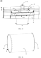
- FIG. 25 To clearly describe a flow direction of the coolant oil in the stator 100 in this implementation, refer to a structure shown in FIG. 25 .
- the first end plate 40a and the second end plate 40b in the extension direction of the iron core punching sheet 20, there is a specific angle difference between the first end plate 40a and the second end plate 40b in the circumferential direction.
- the first notch S1 on the first end plate 40a communicates with a second notch S2 on the second end plate 40b.
- a first flow guiding space P1 in each of the first end plate 40a and the second end plate 40b communicates with a second flow guiding space P2 in the other end plate through the second cooling channel b2.
- a flow direction of the coolant oil in the stator 100 in this implementation is specifically as follows: After flowing to the accommodation cavity from the oil inlet A, the coolant oil enters the first cooling channel b1 that includes the plurality of first oil guiding slots 211 and the inner wall of the housing 10. It should be understood that the first cooling channel b1 is not shown at a sectional angle, and FIG. 25 is merely an example for description. Then, the coolant oil flows from the middle of the iron core punching sheet 20 to two sides along the first cooling channel b1 (the flow direction is shown in a form of two lines). Then, the coolant oil flowing out of the first cooling channel b1 enters the first flow guiding space P1 in the first end plate 40a or the second end plate 40b.
- the coolant oil flows from the first flow guiding space P1 to the second cooling channel b2. Then, the coolant oil flowing out of the second cooling channel b2 enters the second flow guiding space P2 between the end plate on the other side and the iron core punching sheet 20. Then, the coolant oil flows in the second flow guiding space P2.
- the coolant oil may flow in an extension direction of the extension part F.
- Each of the first notch S1 and the second notch S2 corresponds to one stator slot C, and each second flow guiding space P2 surrounds one first notch S 1. Therefore, when the coolant oil flows in the second flow guiding space P2, the coolant oil may reach the slot opening of the stator slot C formed between the adjacent tooth parts 22. Then, the coolant oil flows along the third cooling channel b3 formed through fitting between the slot opening of the stator slot C and the spacer sleeve 30.
- a fastening assembly may be further disposed.
- the disposed fastening assembly includes two fasteners 60 disposed opposite to each other. Specifically, an inner ring of each fastener 60 is disposed on a barrier block R configured to prevent the spacer sleeve 30 from moving in an extension direction.
- FIG. 27 is a diagram of a structure existing after the fastening assembly and the end plate are assembled.
- each fastener 60 corresponds to one of the first end plate 40a or the second end plate 40b, and each fastener 60 is disposed on a side that is of the end plate corresponding to the fastener 60 and that faces away from the other end plate.
- the separation structure W is not limited to the structure shown in FIG. 22 , and there is another implementation.
- FIG. 28 A possible implementation of the separation structure W is shown in FIG. 28 .
- the first end plate 40a is used as an example for description. It should be noted that a difference between the first end plate 40a shown in FIG. 28 and the first end plate 40a shown in FIG. 16 lies in the first separation substructure W1 that surrounds the first notch S1.
- the first separation substructure W1 is connected to an entire extension part F between the first notch S1 and the second notch S2.
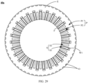
- FIG. 29 Another possible implementation of the separation structure W is shown in FIG. 29 . It should be noted that a difference between the first end plate 40a shown in FIG. 29 and the first end plate 40a shown in FIG. 16 lies in that the separation structure W includes only the first separation substructure W1 that surrounds the first notch S1.
- the first separation substructure W1 is connected to two extension parts F on two sides of the first notch S1, and is connected only to parts that are of the two extension parts F and that are close to the first notch S 1.
- an embodiment of this application further provides a motor 200.
- the motor 200 includes a rotor and any stator 100 provided in the technical solution in the first aspect. It should be understood that the rotor fits with the stator 100 to perform a function.
- a first cooling channel b1, a second cooling channel b2, and a third cooling channel b3 are disposed in the stator 100.
- the coolant oil flowing out of an oil inlet A first flows through the first cooling channel b1 on an outer surface of the stator 100 to preliminarily cool the stator 100.
- the coolant oil enters the second cooling channel b2, and the coolant oil located in the second cooling channel b2 cools the stator 100 again.
- the coolant oil enters the third cooling channel b3, and cools the stator 100 for a third time.
- a cooling requirement of the motor 200 in a low-speed and high-torque working condition and a high-rotation-speed working condition can be ensured by using the three-layer oil-injection design.
- an embodiment of this application further provides an electric vehicle 300.
- FIG. 31 shows a structure of the electric vehicle 300.
- the motor 200 provided in the technical solution in the second aspect is applied to the electric vehicle 300.
- the motor 200 in the electric vehicle 300 is in line with a current trend of a high speed and miniaturization of the motor 200.
Landscapes
- Engineering & Computer Science (AREA)
- Power Engineering (AREA)
- Iron Core Of Rotating Electric Machines (AREA)
- Motor Or Generator Cooling System (AREA)
Priority Applications (1)
| Application Number | Priority Date | Filing Date | Title |
|---|---|---|---|
| EP25198424.1A EP4708642A2 (fr) | 2021-05-21 | 2022-05-09 | Stator, moteur et véhicule électrique |
Applications Claiming Priority (2)
| Application Number | Priority Date | Filing Date | Title |
|---|---|---|---|
| CN202110556357.8A CN114337012B (zh) | 2021-05-21 | 2021-05-21 | 一种定子、电机及电动汽车 |
| PCT/CN2022/091775 WO2022242496A1 (fr) | 2021-05-21 | 2022-05-09 | Stator, moteur électrique et véhicule électrique |
Related Child Applications (2)
| Application Number | Title | Priority Date | Filing Date |
|---|---|---|---|
| EP25198424.1A Division EP4708642A2 (fr) | 2021-05-21 | 2022-05-09 | Stator, moteur et véhicule électrique |
| EP25198424.1A Division-Into EP4708642A2 (fr) | 2021-05-21 | 2022-05-09 | Stator, moteur et véhicule électrique |
Publications (4)
| Publication Number | Publication Date |
|---|---|
| EP4325700A1 true EP4325700A1 (fr) | 2024-02-21 |
| EP4325700A4 EP4325700A4 (fr) | 2024-11-06 |
| EP4325700C0 EP4325700C0 (fr) | 2025-10-01 |
| EP4325700B1 EP4325700B1 (fr) | 2025-10-01 |
Family
ID=81044271
Family Applications (2)
| Application Number | Title | Priority Date | Filing Date |
|---|---|---|---|
| EP25198424.1A Pending EP4708642A2 (fr) | 2021-05-21 | 2022-05-09 | Stator, moteur et véhicule électrique |
| EP22803818.8A Active EP4325700B1 (fr) | 2021-05-21 | 2022-05-09 | Stator, moteur électrique et véhicule électrique |
Family Applications Before (1)
| Application Number | Title | Priority Date | Filing Date |
|---|---|---|---|
| EP25198424.1A Pending EP4708642A2 (fr) | 2021-05-21 | 2022-05-09 | Stator, moteur et véhicule électrique |
Country Status (4)
| Country | Link |
|---|---|
| US (1) | US20240088741A1 (fr) |
| EP (2) | EP4708642A2 (fr) |
| CN (1) | CN114337012B (fr) |
| WO (1) | WO2022242496A1 (fr) |
Families Citing this family (8)
| Publication number | Priority date | Publication date | Assignee | Title |
|---|---|---|---|---|
| CN114337012B (zh) * | 2021-05-21 | 2023-07-18 | 华为数字能源技术有限公司 | 一种定子、电机及电动汽车 |
| CN115333265A (zh) * | 2022-07-20 | 2022-11-11 | 华为数字能源技术有限公司 | 一种定子、电机、动力总成及机械设备 |
| CN119343850A (zh) * | 2022-08-31 | 2025-01-21 | Gkn汽车有限公司 | 具有内部冷却通道的电机定子 |
| DE102023109008A1 (de) * | 2023-04-11 | 2024-10-17 | Schaeffler Technologies AG & Co. KG | Stator, elektrische Rotationsmaschine und Kraftfahrzeug |
| US20240372421A1 (en) * | 2023-05-04 | 2024-11-07 | Garrett Transportation I Inc. | E-machine system with stator core having cooling flow passages |
| CN117498589A (zh) * | 2023-09-26 | 2024-02-02 | 华为数字能源技术有限公司 | 一种定子出液冷却绕组的电机、动力总成及电动汽车 |
| CN117318356A (zh) * | 2023-11-30 | 2023-12-29 | 小米汽车科技有限公司 | 电机和车辆 |
| CN119341230B (zh) * | 2024-12-19 | 2025-03-07 | 东风汽车集团股份有限公司 | 电机定子以及电机 |
Family Cites Families (13)
| Publication number | Priority date | Publication date | Assignee | Title |
|---|---|---|---|---|
| DE102017218828A1 (de) * | 2017-10-23 | 2019-04-25 | Audi Ag | Elektrische Maschine |
| JP7082885B2 (ja) * | 2018-03-08 | 2022-06-09 | 本田技研工業株式会社 | 回転電機のステータ |
| KR20190110676A (ko) * | 2018-03-21 | 2019-10-01 | 엘지전자 주식회사 | 냉매 유로를 갖는 모터의 고정자 구조체 |
| CN109450128B (zh) * | 2018-10-29 | 2020-06-09 | 华中科技大学 | 一种电机定子和具有该电机定子的油冷电机 |
| CN109194037B (zh) * | 2018-10-30 | 2021-06-01 | 清华大学 | 一种隔离电机定子、转子所在空间的油冷电机 |
| CN109980825B (zh) * | 2019-03-27 | 2021-03-09 | 东风汽车集团有限公司 | 一种油冷式电机 |
| CN110601394B (zh) * | 2019-09-27 | 2020-11-24 | 珠海格力电器股份有限公司 | 定子冷却结构、定子组件以及具有其的电机 |
| CN110808645B (zh) * | 2019-11-04 | 2021-11-12 | 合肥巨一动力系统有限公司 | 一种应用于油冷扁线电机定子的冷却结构 |
| CN211456879U (zh) * | 2019-12-31 | 2020-09-08 | 上海汽车集团股份有限公司 | 电机冷却系统 |
| CN211239470U (zh) * | 2020-03-05 | 2020-08-11 | 卧龙电气(上海)中央研究院有限公司 | 一种高功率密度高速永磁同步电机冷却结构 |
| CN112615445B (zh) * | 2020-11-25 | 2022-05-13 | 华为数字能源技术有限公司 | 电机、动力总成和设备 |
| CN113113978B (zh) * | 2021-04-14 | 2022-06-03 | 郑州轻工业大学 | 一种双压力液冷磁通调节装置 |
| CN114337012B (zh) * | 2021-05-21 | 2023-07-18 | 华为数字能源技术有限公司 | 一种定子、电机及电动汽车 |
-
2021
- 2021-05-21 CN CN202110556357.8A patent/CN114337012B/zh active Active
-
2022
- 2022-05-09 EP EP25198424.1A patent/EP4708642A2/fr active Pending
- 2022-05-09 EP EP22803818.8A patent/EP4325700B1/fr active Active
- 2022-05-09 WO PCT/CN2022/091775 patent/WO2022242496A1/fr not_active Ceased
-
2023
- 2023-11-20 US US18/513,724 patent/US20240088741A1/en active Pending
Also Published As
| Publication number | Publication date |
|---|---|
| EP4708642A2 (fr) | 2026-03-11 |
| CN114337012B (zh) | 2023-07-18 |
| EP4325700C0 (fr) | 2025-10-01 |
| EP4325700B1 (fr) | 2025-10-01 |
| US20240088741A1 (en) | 2024-03-14 |
| EP4325700A4 (fr) | 2024-11-06 |
| WO2022242496A1 (fr) | 2022-11-24 |
| CN114337012A (zh) | 2022-04-12 |
Similar Documents
| Publication | Publication Date | Title |
|---|---|---|
| EP4325700A1 (fr) | Stator, moteur électrique et véhicule électrique | |
| EP3913769A1 (fr) | Moteur électrique, système de refroidissement de moteur électrique et véhicule électrique | |
| JP5027169B2 (ja) | アキシャルギャップ型モータ及びそのロータ製造方法 | |
| EP3410570B1 (fr) | Rotor et moteur synchrone à réluctance le comportant | |
| CN114598051A (zh) | 用于车辆的电机及车辆 | |
| EP3337011A1 (fr) | Moteur d'entraînement à refroidissement direct pour véhicule | |
| JP2017017956A (ja) | 回転電機のロータ | |
| CN220067006U (zh) | 定子铁芯、驱动电机和车辆 | |
| CN114598052A (zh) | 用于车辆的电机及车辆 | |
| JP6854700B2 (ja) | 回転電機の回転子、回転電機および圧縮機 | |
| CN119324601A (zh) | 一种定子与喷油组件集成的油冷电机 | |
| CN115149675A (zh) | 定子组件、电机以及车辆 | |
| CN118054587A (zh) | 定子冲片、定子铁芯、电机、动力总成及电动车 | |
| JP5772415B2 (ja) | 回転電機のロータ構造 | |
| CN117424384A (zh) | 电机油冷系统、电机及车辆 | |
| JP2011101461A (ja) | 電動機 | |
| CN114567101A (zh) | 一种油冷电机转子 | |
| CN118713326A (zh) | 电机 | |
| CN115765236A (zh) | 一种用于新能源电机定子冷却结构 | |
| KR102777780B1 (ko) | 구동모터용 회전자 | |
| CN223109739U (zh) | 电机定子铁芯、电机定子、电机及汽车 | |
| KR20240036189A (ko) | 냉각유로를 갖는 모터 | |
| JP2013017334A (ja) | 回転電機 | |
| CN220985387U (zh) | 定子及电机 | |
| CN221886131U (zh) | 定子铁芯及包含该定子铁芯的电机 |
Legal Events
| Date | Code | Title | Description |
|---|---|---|---|
| STAA | Information on the status of an ep patent application or granted ep patent |
Free format text: STATUS: THE INTERNATIONAL PUBLICATION HAS BEEN MADE |
|
| PUAI | Public reference made under article 153(3) epc to a published international application that has entered the european phase |
Free format text: ORIGINAL CODE: 0009012 |
|
| STAA | Information on the status of an ep patent application or granted ep patent |
Free format text: STATUS: REQUEST FOR EXAMINATION WAS MADE |
|
| 17P | Request for examination filed |
Effective date: 20231116 |
|
| AK | Designated contracting states |
Kind code of ref document: A1 Designated state(s): AL AT BE BG CH CY CZ DE DK EE ES FI FR GB GR HR HU IE IS IT LI LT LU LV MC MK MT NL NO PL PT RO RS SE SI SK SM TR |
|
| DAV | Request for validation of the european patent (deleted) | ||
| DAX | Request for extension of the european patent (deleted) | ||
| A4 | Supplementary search report drawn up and despatched |
Effective date: 20241007 |
|
| RIC1 | Information provided on ipc code assigned before grant |
Ipc: H02K 5/20 20060101ALI20240930BHEP Ipc: H02K 3/24 20060101ALI20240930BHEP Ipc: H02K 1/20 20060101ALI20240930BHEP Ipc: H02K 9/19 20060101AFI20240930BHEP |
|
| GRAP | Despatch of communication of intention to grant a patent |
Free format text: ORIGINAL CODE: EPIDOSNIGR1 |
|
| STAA | Information on the status of an ep patent application or granted ep patent |
Free format text: STATUS: GRANT OF PATENT IS INTENDED |
|
| INTG | Intention to grant announced |
Effective date: 20250519 |
|
| GRAS | Grant fee paid |
Free format text: ORIGINAL CODE: EPIDOSNIGR3 |
|
| GRAA | (expected) grant |
Free format text: ORIGINAL CODE: 0009210 |
|
| STAA | Information on the status of an ep patent application or granted ep patent |
Free format text: STATUS: THE PATENT HAS BEEN GRANTED |
|
| AK | Designated contracting states |
Kind code of ref document: B1 Designated state(s): AL AT BE BG CH CY CZ DE DK EE ES FI FR GB GR HR HU IE IS IT LI LT LU LV MC MK MT NL NO PL PT RO RS SE SI SK SM TR |
|
| REG | Reference to a national code |
Ref country code: GB Ref legal event code: FG4D Ref country code: CH Ref legal event code: F10 Free format text: ST27 STATUS EVENT CODE: U-0-0-F10-F00 (AS PROVIDED BY THE NATIONAL OFFICE) Effective date: 20251001 |
|
| REG | Reference to a national code |
Ref country code: DE Ref legal event code: R096 Ref document number: 602022022405 Country of ref document: DE |
|
| REG | Reference to a national code |
Ref country code: IE Ref legal event code: FG4D |
|
| U01 | Request for unitary effect filed |
Effective date: 20251001 |
|
| U07 | Unitary effect registered |
Designated state(s): AT BE BG DE DK EE FI FR IT LT LU LV MT NL PT RO SE SI Effective date: 20251009 |
|
| PG25 | Lapsed in a contracting state [announced via postgrant information from national office to epo] |
Ref country code: ES Free format text: LAPSE BECAUSE OF FAILURE TO SUBMIT A TRANSLATION OF THE DESCRIPTION OR TO PAY THE FEE WITHIN THE PRESCRIBED TIME-LIMIT Effective date: 20251001 |
|
| PG25 | Lapsed in a contracting state [announced via postgrant information from national office to epo] |
Ref country code: NO Free format text: LAPSE BECAUSE OF FAILURE TO SUBMIT A TRANSLATION OF THE DESCRIPTION OR TO PAY THE FEE WITHIN THE PRESCRIBED TIME-LIMIT Effective date: 20260101 |
|
| PG25 | Lapsed in a contracting state [announced via postgrant information from national office to epo] |
Ref country code: HR Free format text: LAPSE BECAUSE OF FAILURE TO SUBMIT A TRANSLATION OF THE DESCRIPTION OR TO PAY THE FEE WITHIN THE PRESCRIBED TIME-LIMIT Effective date: 20251001 |
|
| PG25 | Lapsed in a contracting state [announced via postgrant information from national office to epo] |
Ref country code: RS Free format text: LAPSE BECAUSE OF FAILURE TO SUBMIT A TRANSLATION OF THE DESCRIPTION OR TO PAY THE FEE WITHIN THE PRESCRIBED TIME-LIMIT Effective date: 20260101 |
|
| PG25 | Lapsed in a contracting state [announced via postgrant information from national office to epo] |
Ref country code: IS Free format text: LAPSE BECAUSE OF FAILURE TO SUBMIT A TRANSLATION OF THE DESCRIPTION OR TO PAY THE FEE WITHIN THE PRESCRIBED TIME-LIMIT Effective date: 20260201 |
|
| PG25 | Lapsed in a contracting state [announced via postgrant information from national office to epo] |
Ref country code: CZ Free format text: LAPSE BECAUSE OF FAILURE TO SUBMIT A TRANSLATION OF THE DESCRIPTION OR TO PAY THE FEE WITHIN THE PRESCRIBED TIME-LIMIT Effective date: 20251001 |
|
| PG25 | Lapsed in a contracting state [announced via postgrant information from national office to epo] |
Ref country code: PL Free format text: LAPSE BECAUSE OF FAILURE TO SUBMIT A TRANSLATION OF THE DESCRIPTION OR TO PAY THE FEE WITHIN THE PRESCRIBED TIME-LIMIT Effective date: 20251001 |