EP4326196B1 - Katheterstabilisierungsvorrichtungen - Google Patents
Katheterstabilisierungsvorrichtungen Download PDFInfo
- Publication number
- EP4326196B1 EP4326196B1 EP22723473.9A EP22723473A EP4326196B1 EP 4326196 B1 EP4326196 B1 EP 4326196B1 EP 22723473 A EP22723473 A EP 22723473A EP 4326196 B1 EP4326196 B1 EP 4326196B1
- Authority
- EP
- European Patent Office
- Prior art keywords
- catheter
- stabilizer
- stabilization system
- implementations
- stabilize
- Prior art date
- Legal status (The legal status is an assumption and is not a legal conclusion. Google has not performed a legal analysis and makes no representation as to the accuracy of the status listed.)
- Active
Links
Images









Classifications
-
- A—HUMAN NECESSITIES
- A61—MEDICAL OR VETERINARY SCIENCE; HYGIENE
- A61F—FILTERS IMPLANTABLE INTO BLOOD VESSELS; PROSTHESES; DEVICES PROVIDING PATENCY TO, OR PREVENTING COLLAPSING OF, TUBULAR STRUCTURES OF THE BODY, e.g. STENTS; ORTHOPAEDIC, NURSING OR CONTRACEPTIVE DEVICES; FOMENTATION; TREATMENT OR PROTECTION OF EYES OR EARS; BANDAGES, DRESSINGS OR ABSORBENT PADS; FIRST-AID KITS
- A61F2/00—Filters implantable into blood vessels; Prostheses, i.e. artificial substitutes or replacements for parts of the body; Appliances for connecting them with the body; Devices providing patency to, or preventing collapsing of, tubular structures of the body, e.g. stents
- A61F2/02—Prostheses implantable into the body
- A61F2/24—Heart valves ; Vascular valves, e.g. venous valves; Heart implants, e.g. passive devices for improving the function of the native valve or the heart muscle; Transmyocardial revascularisation [TMR] devices; Valves implantable in the body
- A61F2/2427—Devices for manipulating or deploying heart valves during implantation
- A61F2/2436—Deployment by retracting a sheath
-
- A—HUMAN NECESSITIES
- A61—MEDICAL OR VETERINARY SCIENCE; HYGIENE
- A61M—DEVICES FOR INTRODUCING MEDIA INTO, OR ONTO, THE BODY; DEVICES FOR TRANSDUCING BODY MEDIA OR FOR TAKING MEDIA FROM THE BODY; DEVICES FOR PRODUCING OR ENDING SLEEP OR STUPOR
- A61M25/00—Catheters; Hollow probes
- A61M25/01—Introducing, guiding, advancing, emplacing or holding catheters
- A61M25/02—Holding devices, e.g. on the body
- A61M25/04—Holding devices, e.g. on the body in the body, e.g. expansible
-
- A—HUMAN NECESSITIES
- A61—MEDICAL OR VETERINARY SCIENCE; HYGIENE
- A61M—DEVICES FOR INTRODUCING MEDIA INTO, OR ONTO, THE BODY; DEVICES FOR TRANSDUCING BODY MEDIA OR FOR TAKING MEDIA FROM THE BODY; DEVICES FOR PRODUCING OR ENDING SLEEP OR STUPOR
- A61M25/00—Catheters; Hollow probes
- A61M25/0067—Catheters; Hollow probes characterised by the distal end, e.g. tips
- A61M25/0074—Dynamic characteristics of the catheter tip, e.g. openable, closable, expandable or deformable
-
- A—HUMAN NECESSITIES
- A61—MEDICAL OR VETERINARY SCIENCE; HYGIENE
- A61M—DEVICES FOR INTRODUCING MEDIA INTO, OR ONTO, THE BODY; DEVICES FOR TRANSDUCING BODY MEDIA OR FOR TAKING MEDIA FROM THE BODY; DEVICES FOR PRODUCING OR ENDING SLEEP OR STUPOR
- A61M25/00—Catheters; Hollow probes
- A61M25/01—Introducing, guiding, advancing, emplacing or holding catheters
- A61M25/0105—Steering means as part of the catheter or advancing means; Markers for positioning
- A61M25/0133—Tip steering devices
-
- A—HUMAN NECESSITIES
- A61—MEDICAL OR VETERINARY SCIENCE; HYGIENE
- A61F—FILTERS IMPLANTABLE INTO BLOOD VESSELS; PROSTHESES; DEVICES PROVIDING PATENCY TO, OR PREVENTING COLLAPSING OF, TUBULAR STRUCTURES OF THE BODY, e.g. STENTS; ORTHOPAEDIC, NURSING OR CONTRACEPTIVE DEVICES; FOMENTATION; TREATMENT OR PROTECTION OF EYES OR EARS; BANDAGES, DRESSINGS OR ABSORBENT PADS; FIRST-AID KITS
- A61F2/00—Filters implantable into blood vessels; Prostheses, i.e. artificial substitutes or replacements for parts of the body; Appliances for connecting them with the body; Devices providing patency to, or preventing collapsing of, tubular structures of the body, e.g. stents
- A61F2/02—Prostheses implantable into the body
- A61F2/24—Heart valves ; Vascular valves, e.g. venous valves; Heart implants, e.g. passive devices for improving the function of the native valve or the heart muscle; Transmyocardial revascularisation [TMR] devices; Valves implantable in the body
- A61F2/2442—Annuloplasty rings or inserts for correcting the valve shape; Implants for improving the function of a native heart valve
- A61F2/2466—Delivery devices therefor
-
- A—HUMAN NECESSITIES
- A61—MEDICAL OR VETERINARY SCIENCE; HYGIENE
- A61M—DEVICES FOR INTRODUCING MEDIA INTO, OR ONTO, THE BODY; DEVICES FOR TRANSDUCING BODY MEDIA OR FOR TAKING MEDIA FROM THE BODY; DEVICES FOR PRODUCING OR ENDING SLEEP OR STUPOR
- A61M25/00—Catheters; Hollow probes
- A61M25/0067—Catheters; Hollow probes characterised by the distal end, e.g. tips
- A61M25/0074—Dynamic characteristics of the catheter tip, e.g. openable, closable, expandable or deformable
- A61M2025/0079—Separate user-activated means, e.g. guidewires, guide tubes, balloon catheters or sheaths, for sealing off an orifice, e.g. a lumen or side holes, of a catheter
-
- A—HUMAN NECESSITIES
- A61—MEDICAL OR VETERINARY SCIENCE; HYGIENE
- A61M—DEVICES FOR INTRODUCING MEDIA INTO, OR ONTO, THE BODY; DEVICES FOR TRANSDUCING BODY MEDIA OR FOR TAKING MEDIA FROM THE BODY; DEVICES FOR PRODUCING OR ENDING SLEEP OR STUPOR
- A61M2210/00—Anatomical parts of the body
- A61M2210/12—Blood circulatory system
- A61M2210/125—Heart
Definitions
- Endovascular delivery systems can be used in various procedures to deliver medical devices or instruments to a target location inside a patient's body that are not readily accessible by surgery or where access without surgery is desirable.
- the systems described herein can be used to deliver medical devices (e.g., stents, heart valve, grafts, clips, repair devices, valve treatment devices, etc.) to a location in a patient's body.
- Access to a target location inside the patient's body can be achieved by inserting and guiding the delivery system through a pathway or lumen in the body, including, but not limited to, a blood vessel, an esophagus, a trachea, any portion of the gastrointestinal tract, a lymphatic vessel, to name a few.
- a pathway or lumen in the body including, but not limited to, a blood vessel, an esophagus, a trachea, any portion of the gastrointestinal tract, a lymphatic vessel, to name a few.
- Catheters are known in the art and have been commonly used to reach target locations inside a patient's body.
- a catheter is used to deliver a device for repairing a native heart valve.
- the native heart valves i.e., the aortic, pulmonary, tricuspid, and mitral valves
- These heart valves can be damaged, and thus rendered less effective, for example, by congenital malformations, inflammatory processes, infectious conditions, disease, etc. Such damage to the valves can result in serious cardiovascular compromise or death. Damaged valves can be surgically repaired or replaced during open heart surgery. However, open heart surgeries are highly invasive, and complications may occur. Transvascular techniques can be used to introduce and implant prosthetic devices in a manner that is much less invasive than open heart surgery.
- a transvascular technique useable for accessing the native mitral and aortic valves is the trans-septal technique.
- the trans-septal technique comprises advancing a catheter into the right atrium (e.g., inserting a catheter into the right femoral vein, up the inferior vena cava and into the right atrium). The septum is then punctured, and the catheter passed into the left atrium.
- a similar transvascular technique can be used to implant a prosthetic device within the tricuspid valve that begins similarly to the trans-septal technique but stops short of puncturing the septum and instead turns the delivery catheter toward the tricuspid valve in the right atrium.
- Catheters can be used in procedures involving various implants, such as annuloplasty rings (which can reshape a heart valve), valve repair devices (which can repair existing heart valves), implantable heart valve replacement devices, docking stations for heart valve replacement devices, etc.
- WO 2005/062931 A2 relates to catheter based systems for securing tissue including the annulus of a mitral valve.
- the systems employ catheter based techniques and devices to plicate tissue and perform an annuloplasty.
- Magnets may be used for guidance in deploying fasteners from a catheter.
- the fasteners are cinched with a flexible tensile member.
- a catheter stabilization system or device includes a catheter and a stabilizer.
- the catheter has a steerable distal end.
- the stabilizer is coupled with the catheter at a position that is proximal to the steerable distal end.
- the stabilizer is movable radially outward relative to the catheter (e.g., from a non-expanded or non-extended position/state/configuration to an actuated or expanded position/state/configuration) to stabilize the catheter during flexing of the distal end of the steerable catheter.
- the stabilizer is configured to be actuated to engage vasculature to stabilize the catheter. In some implementations, the stabilizer is configured to be expanded to engage vasculature to stabilize the catheter.
- the catheter comprises one or more of a guide sheath, sleeve, steerable catheter, and/or an implant catheter.
- the stabilizer is configured such that, in a non-expanded state, the stabilizer is flush with the catheter.
- the stabilizer comprises one or more extensions (e.g., one or more legs, one or more skis, one or more fins, one or more inflatable members, a combination of these, etc.) coupled with the catheter.
- the extensions e.g., legs, skis, fins, inflatable members, combinations of different types of extensions, etc.
- the stabilizer comprises a channel and wire within the channel or multiple wires.
- the wire or wires can be a shape-set wire or shape-set wires.
- the wire(s) extends curls back towards the catheter upon being forced from the channel.
- the stabilizer comprises a mesh material.
- the mesh material is a shape-set mesh material.
- the shape set mesh curls back towards the catheter upon being pushed out of the catheter.
- a catheter stabilization system or device includes a sleeve, a catheter, and a stabilizer.
- the catheter has a steerable distal end.
- the stabilizer is coupled with the sleeve.
- the stabilizer is movable radially outward relative to the sleeve (e.g., from a non-expanded or non-extended position/state/configuration to an actuated or expanded position/state/configuration) to stabilize the sleeve and/or the catheter during flexing of the distal end of the steerable catheter.
- the stabilizer is configured to engage the vasculature.
- the catheter comprises at least one of a guide sheath, a steerable catheter, and an implant catheter.
- the stabilizer is disposed or positionable proximal to a distal tip of the sleeve.
- the stabilizer in a non-expanded state/configuration, is flush with the catheter and/or the sleeve.
- the stabilizer comprises one or more extensions coupled with the sleeve and/or with the catheter.
- the extensions comprise one or more of legs, skis, fins, inflatable members, wires, mesh, etc.
- the extensions are configured to actuate, move, expand, extend, etc. radially outward (e.g., from a non-expanded or non-extended position/state/configuration to an actuated or expanded position/state/configuration).
- the stabilizer comprises a channel and wire within the channel or multiple wires.
- the wire or wires can be a shape-set wire or shape-set wires.
- the wire(s) extends curls back towards the catheter upon being forced from the channel.
- the stabilizer comprises a mesh material.
- the mesh material is a shape-set mesh material.
- the shape set mesh curls back towards the catheter upon being pushed out of the catheter.
- a method of stabilizing a catheter comprises advancing one or more of a catheter, a stabilizer, and/or a combination of these through vasculature of a patient.
- the method includes actuating, expanding, or extending the stabilizer to engage the vasculature.
- the method can include expanding or extending the stabilizer (e.g., extensions, legs, skis, fins, inflatable portions, one or more other portions of the stabilizer, etc.) radially outward from the catheter to engage the vasculature.
- the method can further include flexing or steering a distal end of the catheter while the stabilizer is coupled or engaged with the vasculature, e.g., to perform a treatment (such as a repair or replacement procedure, an annuloplasty procedure, an implantation, etc.).
- a treatment such as a repair or replacement procedure, an annuloplasty procedure, an implantation, etc.
- the method further comprises advancing a sheath through the vasculature of a patient, wherein the sheath is disposed radially outward of the catheter and the stabilizer.
- the sheath is removed from at least a portion of the vasculature after the catheter and the stabilizer are advanced through the stabilizer.
- the catheter and the stabilizer are coupled such that they advance through the vasculature at the same time. In some implementations, the catheter and the stabilizer are uncoupled such that they advance through the vasculature at different times.
- actuating, expanding, or extending the stabilizer comprises extending one or more extensions (e.g., legs, skis, fins, inflatable members, combination of different types of extensions, etc.) of the stabilizer radially outward. In some implementations, actuating, expanding, or extending the stabilizer comprises extending one or more legs of the stabilizer radially outward. In some implementations, actuating, expanding, or extending the stabilizer comprises extending one or more skis of the stabilizer radially outward. In some implementations, actuating, expanding, or extending the stabilizer comprises extending one or more fins of the stabilizer radially outward.
- extensions e.g., legs, skis, fins, inflatable members, combination of different types of extensions, etc.
- actuating, expanding, or extending the stabilizer comprises inflating one or more inflatable members of the stabilizer radially outward. In some implementations, actuating, expanding, or extending the stabilizer comprises extending a wire (e.g., a shape-set wire) from a channel of the stabilizer. In some implementations, actuating, expanding, or extending the stabilizer comprises extending a shape-set sheet from a channel of the stabilizer.
- actuating, expanding, or extending the stabilizer comprises inflating one or more inflatable members of the stabilizer radially outward. In some implementations, actuating, expanding, or extending the stabilizer comprises extending a wire (e.g., a shape-set wire) from a channel of the stabilizer. In some implementations, actuating, expanding, or extending the stabilizer comprises extending a shape-set sheet from a channel of the stabilizer.
- the above method(s) can be performed on a living animal or on a simulation, such as on a cadaver, cadaver heart, simulator (e.g., with the body parts, heart, tissue, etc. being simulated), etc.
- a simulation such as on a cadaver, cadaver heart, simulator (e.g., with the body parts, heart, tissue, etc. being simulated), etc.
- a catheter stabilization system includes a catheter, a stabilizer, and a valve repair or replacement system, device, or implant.
- the catheter has a steerable distal end.
- the stabilizer is coupled with the catheter at a position that is proximal to the steerable distal end.
- the stabilizer is movable radially outward relative to the catheter to stabilize the catheter during flexing of the distal end of the steerable catheter to position the valve repair or replacement system, device, or implant.
- the valve repair or replacement system, device, or implant comprises one or more of a valve repair device, an annuloplasty system, an annuloplasty structure, an annuloplasty ring, an implantable valve replacement device, a docking station for valve a replacement device, etc. Any of the systems, devices, stabilizers herein can be used to deliver the valve repair or replacement system, device, or implant.
- the valve repair or replacement system, device, or implant is configured to be delivered transluminally or transvascularly.
- the valve repair or replacement system, device, or implant includes multiple anchors (e.g., helical anchors, dart-like anchors, staple-like anchors, clips, etc.) that are delivered/anchored or configured to be delivered/anchored at multiple locations of a native heart valve (e.g., at multiple locations around an annulus of a native heart valve of a heart).
- the stabilizer can be configured to allow precise location and placement of the multiple anchors at the multiple locations.
- the valve repair or replacement system, device, or implant comprises an annuloplasty system, structure, device, or ring that comprises multiple anchors and a tether or tensioning member that can be tensioned such that a shape and/or size of the annulus of the native heart valve is changed (e.g., by pulling the anchors closer together, etc.).
- the annuloplasty system, structure, device, or ring comprises spacers that help space the multiple anchors apart and/or help distribute forces between the anchors (e.g., the annuloplasty system, structure, device, or ring can comprise a tether or tensioning member that passes through eyelets of multiple anchors and through a lumen or center of spacers between the anchors.) Precise placement of the anchors is facilitated by the stabilizer by providing more control over the movement of the catheter while delivering the anchors.
- Example implementations of the present disclosure are directed to devices and methods for steering a flexible delivery system for a medical device, such as a catheter.
- a medical device such as a catheter.
- These example delivery systems provide a wide range of motion for the positioning of a medical device and are versatile, reliable, and easy to use.
- the delivery systems disclosed herein can be used to position and deploy an implantable medical device for use in the repair of a native heart valve.
- native valve reparation devices and systems for delivery are disclosed herein, and any combination of these options can be made unless specifically excluded.
- individual components of the disclosed devices and systems can be combined unless mutually exclusive or otherwise physically impossible.
- interconnection when one or more components are described as being connected, joined, affixed, coupled, attached, or otherwise interconnected, such interconnection may be direct as between the components or may be indirect such as through the use of one or more intermediary components.
- reference to a "member,” “component,” or “portion” shall not be limited to a single structural member, component, or element but can include an assembly of components, members, or elements.
- the terms “substantially” and “about” are defined as at least close to (and includes) a given value or state (preferably within 10% of, more preferably within 1% of, and most preferably within 0.1% of).
- the catheters When introducing a catheter into the heart, it can be necessary to locate and use existing anatomy to support, secure, or otherwise stabilize the catheter.
- the catheters When navigating around the mitral valve, for example, the catheters can be stabilized by the septum for the subsequent procedure.
- the anatomy is not accessible to support, secure, or otherwise stabilize the catheter.
- heart anatomy may be too large to stabilize the catheter when attempting to treat the tricuspid valve. In cases like this, navigating around the heart can be challenging due to a lack of support for the delivery system.
- the present application discloses example implementations of stabilizing arrangements that stabilize components of a delivery system, such as a delivery sheath, a steerable catheter, a device catheter, a device pusher, a guidewire, etc. during delivery of a device, such as a valve repair device, a valve repair device, a heart wall remodeling system, etc.
- a delivery system such as a delivery sheath, a steerable catheter, a device catheter, a device pusher, a guidewire, etc.
- a device such as a valve repair device, a valve repair device, a heart wall remodeling system, etc.
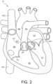
- FIGS 1 and 2 are cutaway views of the human heart H in diastolic and systolic phases, respectively.
- the right ventricle RV and left ventricle LV are separated from the right atrium RA and left atrium LA, respectively, by the tricuspid valve TV and mitral valve MV, respectively; i.e., the atrioventricular valves.
- the aortic valve AV separates the left ventricle LV from the ascending aorta AA
- the pulmonary valve PV separates the right ventricle from the pulmonary artery PA.
- Each of these valves has flexible leaflets (not shown) extending inward across the respective orifices that come together or "coapt" in the flow stream to form the one-way, fluid-occluding surfaces.
- the native valve repair systems of the present application are described primarily with respect to the tricuspid valve TV. Therefore, anatomical structures of the right atrium RA and right ventricle RV will be explained in greater detail. It should be understood that the devices described herein may also be used in repairing other native valves, e.g., the devices can be used in repairing the mitral valve MV, the aortic valve AV, and the pulmonary valve PV.
- the superior vena cava SVC returns all of the blood to the heart from tissues superior to the heart in the head, neck, arms, and upper thorax.
- the inferior vena cava IVC returns blood to the heart from tissues inferior to the heart, including the legs, abdomen, and lower thorax. Blood from the exterior of the heart itself is collected in the coronary sinus CS to be returned to the interior of the heart.
- the left atrium LA receives oxygenated blood from the lungs.
- blood in the left atrium LA moves through the mitral valve MV and into the left ventricle LV by expansion of the left ventricle LV.
- the left ventricle LV contracts to force the blood through the aortic valve AV and ascending aorta AA into the body.
- the leaflets of the mitral valve MV close to prevent the blood from regurgitating from the left ventricle LV back into the left atrium LA.
- the devices described by the present application are used during the repair or replacement of a native heart valve, such as the Mitral Valve, the Tricuspid Valve, the Pulmonary Valve, or the Aortic Valve.
- a native heart valve such as the Mitral Valve, the Tricuspid Valve, the Pulmonary Valve, or the Aortic Valve.
- the stabilizers are shown being used to navigate to the tricuspid valve TV.
- the stabilizers can be used with any system that accesses any of the native valves of the heart.
- the stabilizers are configured to utilize existing heart anatomy to provide support to the delivery system, such as one or more catheters of the delivery system.
- the catheter and related devices can help repair and/or replace the leaflets of the tricuspid valve TV to prevent blood from regurgitating from the right ventricle RV and back into the right atrium RA.
- a catheter stabilizing system 10 includes a catheter 20 comprising a stabilizer 30 or includes a stabilizer 30 configured to be used with a catheter 20.
- the stabilizer 30 can be used on a wide variety of catheters.
- the catheter 20 can be a guide sheath, steerable catheter, an implant catheter, and implant pusher, etc.
- the catheter stabilizing device 10 can include a stabilizer 30 having a wide variety of forms, some of which are described herein.
- the stabilizer 30 can include any structure that can be actuated, expanded, extended, secured, anchored, leveraged, or can otherwise be used to stabilize the catheter 20 during the flexing of the catheter 20.
- the stabilizer 30 can be actuated (e.g., expanded, extended, secured, anchored, leveraged, stabilized, etc.) in a variety of ways against patient vasculature to stabilize the catheter 20 during various procedures.
- the stabilizer 30 is configured to expand, extend, etc. to various diameters and/or increased size as needed based on the size of the patient's vasculature.
- the stabilizer 30 can be configured to thereafter contract to a diameter and/or reduced size that is smaller than the maximum diameter and/or size, as needed based on the location of the catheter 20 in the patient and the vasculature that is being used for stabilization.
- the stabilizer 30 in a compressed or reduced size state/configuration, can be flush or substantially flush with the catheter 20. In some instances, in the non-expanded, compressed, or reduced size state/configuration, the stabilizer 30 can extend partially radially outward from the catheter. When the stabilizer 30 is actuated, expanded, extended, etc. to an actuated state/configuration or expanded state/configuration, the stabilizer 30 can extend from the catheter 20 to the vasculature of the patient.
- the stabilizer 30 can be coupleable to the catheter 20 or can be integral with the catheter 20 itself. In some implementations, the stabilizer 30 can be located proximal to the distal tip 22 of the catheter 20. The stabilizer 30 can be located in various other locations of the catheter 20 as needed based on the location of the catheter 20 in the patient and the vasculature that is being used for stabilization.
- the stabilizer 30 can comprise a non-expanded, compressed, or reduced size state/configuration (see Figure 3 ) as well as an actuated or expanded state/configuration ( Figure 4 ).
- the stabilizer 30 can take a wide variety of different forms.
- the stabilizer 30 can be an inflatable device, such as a bladder or a balloon, a mechanical linkage, one or more extendable members, etc.
- the stabilizer can be any structure or can comprise any structure that can move from a retracted or compressed condition to an actuated or expanded condition.
- the catheter 20 is located in a patient body, for example, in a blood vessel 40.
- the catheter 20 can be positioned through the blood vessel or vasculature 40.
- the blood vessel or vasculature 40 can be any vessel of the circulatory system, heart, any cavity of the heart, any vessel or vasculature that is in direct communication with the heart, etc.
- the stabilizer 30 can be actuated (e.g., expanded, extended, etc.) ( Figure 6 ) such that it couples with or engages the blood vessel or vasculature 40 to stabilize the catheter 20 within the blood vessel or vasculature 40. Once the stabilizer 30 couples with or engages the blood vessel or vasculature 40, the tip 22 of the catheter can be accurately positioned and stabilized to deliver or deploy the repair or replacement device.
- Figures 7 and 8 illustrate an example of a delivery system that includes a stabilizer or catheter stabilizing device 110.
- the catheter stabilizing device 110 can include a stabilizer 130 located or coupleable on a sleeve 150.
- Figure 7 illustrates the sleeve 150 comprising the stabilizer 130 in a non-expanded state/configuration or reduced size state/configuration
- Figure 8 illustrates the sleeve 150 comprising the stabilizer 130 in an actuated or expanded state/configuration.
- the catheter 120 is in the sleeve in this example.
- the stabilizer 130 can be actuated or expanded such that it couples with the blood vessel 140 to stabilize the sleeve 150, and thus, the catheter 120 within the blood vessel 140.
- the catheter stabilizing device can include a stabilizer located on the sleeve as well as on the catheter. This could be beneficial if there are multiple structures of different sizes which can be used to stabilize the catheter. Any of the implementations described herein can comprise devices wherein the stabilizer is located on the catheter 20 (see Figures 3-6 ) or on the sleeve (see Figures 7-8 ), or on both the catheter and the sleeve.
- the catheter stabilizing device 10 can go into any vasculature to provide stability to access any area of the heart, including, but not limited to the mitral valve MV, the aortic valve AV, the pulmonary valve PV, and the tricuspid valve TV.
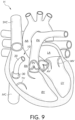
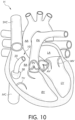
- a catheter stabilizing device 10 is deployed through the inferior vena cava IVC to access the tricuspid valve TV. This can help stabilize the catheter within the IVC to allow more precise treatment at the tricuspid valve (e.g., without the catheter moving and thereby moving the location of the distal end of the catheter from a desired treatment location).
- the catheter 20 is positioned within the right atrium RA while the stabilizer 30 is positioned within the inferior vena cava IVC.
- the stabilizer 30 can be actuated or expanded to an actuated or expended state/configuration wherein the stabilizer 30 (e.g., an outer surface, extension(s), leg(s), ski(s), fin(s), other portion, etc.) is pressed against an inner surface or region of the inferior vena cava IVC to stabilize the catheter 20 within the inferior vena cava IVC.
- the catheter 20 can then be repositioned or steered to get to a desired position. The steering of the catheter 20 is supported by the stabilization of the stabilizer 30 against the inferior vena cava IVC.
- a delivery catheter 70 is introduced through the catheter 20.
- a system, device, or implant 80 can be introduced through the delivery catheter 70 (and or with any of the systems, devices, catheters, etc. herein) to assist in the repair or replacement of the tricuspid valve or other valves.
- the system, device, or implant 80 can comprise any device for repairing or replacing any portion of any heart valve.
- systems, devices, or implants 80 include, but are not limited to, annuloplasty structures, annuloplasty systems, annuloplasty rings, valve repair devices, valve replacement devices, and docking stations for heart valve replacement devices.
- system, device, or implant 80 can comprise any of the systems, devices, and/or implants in US Patent 9,636,224 , PCT Application No. PCT/IB2020/060044 , US Patent Application No. 63/130,364 , US Patent Application No. 63/113,430 , and US Patent Application No. 63/124,704 .
- the system, device, or implant 80 is configured to be delivered transluminally or transvascularly.
- the system, device, or implant 80 includes multiple anchors (e.g., helical anchors, dart-like anchors, staple-like anchors, clips, etc.) that are delivered/anchored or configured to be delivered/anchored at multiple locations of a native heart valve (e.g., at multiple locations around an annulus of a native heart valve of a heart).
- the stabilizer can be configured to allow precise location and placement of the multiple anchors at the multiple locations.
- the system, device, or implant 80 comprises an annuloplasty system, structure, device, or ring that comprises multiple anchors and a tether or tensioning member that can be tensioned such that a shape and/or size of the annulus of the native heart valve is changed (e.g., by pulling the anchors closer together, etc.).
- the annuloplasty system, structure, device, or ring comprises spacers that help space the multiple anchors apart and/or help distribute forces between the anchors (e.g., the annuloplasty system, structure, device, or ring can comprise a tether or tensioning member that passes through eyelets of multiple anchors and through a lumen or center of spacers between the anchors.) Precise placement of the anchors is facilitated by the stabilizer by providing more control over the movement of the catheter while delivering the anchors.
- a catheter stabilizing device 210 can comprise a stabilizer 230.
- the stabilizer 230 can be located on the catheter and/or on the sleeve, as described herein.
- the stabilizer 230 can include one or more extensions or legs 232. Any structure that can move the legs 232 from a more radially inward or non-extended position/configuration to a more radially outward or extended position/configuration can be used.
- the legs 232 can be attached to wires 234 on the distal end 236 of the legs 232.
- an actuator (not shown) can push or pull on the wires 234, which in turn pull the distal end 236 of the legs 232 radially outward relative to the catheter 220 to an actuated or expanded/extended state/configuration.
- the legs 232 when the legs 232 are pulled outward, they reach and press against the blood vessel or vasculature 240 to stabilize the catheter 220 within the blood vessel or vasculature 240.
- the stabilizer 230 can include two legs 232, however any number of legs 232 can be used.
- Figures 18-21 illustrate an example of a catheter stabilizing device.
- the catheter stabilizing device 310 can comprise a stabilizer 330.
- the stabilizer 330 can be located on the catheter and/or on the sleeve, as described herein.
- the stabilizer 330 can include one or more extensions or skis 332.
- the skis 332 can be moved radially outward relative to the catheter 320 to an actuated or expanded state/configuration. Any structure that can move the skis 332 from a more radially inward or non-extended position/configuration to a more radially outward or extended position/configuration can be used.
- the skis 332 can be attached to wires 333 (see Figures 19 and 20 ).
- an optional actuator can push on the wires 333, which in turn push the skis 332 radially outward relative to the catheter 320 to an actuated or expanded/extended state/configuration.
- the skis 332 When the skis 332 are pushed outward, they can reach and press against a blood vessel or other vasculature structure to stabilize the catheter 320 within that structure.
- the stabilizer 330 can include two skis 332, however any number of skis 332 can be used.
- a catheter stabilizing device 410 can comprise a stabilizer 430.
- the stabilizer 430 can extend from the catheter and/or extend from the sleeve.
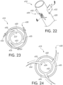
- the stabilizer 430 can include one or more extensions or fins 432.
- the fins 432 can be moved radially outward relative to the catheter 420 to an actuated or expanded state/configuration. Any structure that can allow the fins 432 to move from a more radially inward or non-extended position/configuration to a more radially outward or extended position/configuration can be used.
- the fins 432 are attached to a central shaft 433 and extend through openings 435 of the outer wall of the catheter or sleeve.
- the shaft 433 when the shaft 433 is rotated in the direction 437, the fins 432 are drawn through the openings 435 into the catheter 420 by the shaft 433 to retract the fins.
- the fins 432 when the shaft 433 is rotated in the direction 439, the fins 432 are pushed out of the openings 435 of the catheter 420 by the shaft 433 to extend the fins to an actuated or extended state/configuration.
- an actuator can be used to extend and retract the fins 432.
- the stabilizer 430 can include three fins 432, however two, four, five, or any number of fins 432 can be used.
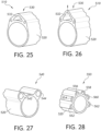
- Figures 25-28 illustrate examples of catheter stabilizing devices.
- the catheter stabilizing device 510 can comprise a stabilizer 530.
- the stabilizer 530 can be located on the catheter or on the sleeve, as described herein.
- the stabilizer 530 can include one or more inflatable members or portions 532.
- the inflatable member 532 can be inflated to expand radially outward relative to the catheter 520 to an actuated or expanded state/configuration. Any structure that can allow the inflatable member 532 to inflate or otherwise expand from a more radially inward or non-extended position/configuration to a more radially outward or extended position/configuration can be used.
- a pump, syringe, etc. can force fluid, such as gas (e.g., air, nitrogen, etc.) or liquid (e.g., water, saline solution, etc.) into the inflatable member 532 to inflate the inflatable member 532.
- fluid such as gas (e.g., air, nitrogen, etc.) or liquid (e.g., water, saline solution, etc.) into the inflatable member 532 to inflate the inflatable member 532.
- the inflatable member 532 expands radially outward relative to the catheter 520.
- the inflatable member(s) 532 When the inflatable member(s) 532 are inflated and expand outward, they can reach and press against a blood vessel or other vasculature structure to stabilize the catheter 520 within that structure.
- the stabilizer 530 can include one inflatable member 532.
- the stabilizer 540 can include two inflatable members 542, 544.
- the stabilizer 550 can include six inflatable members 552, 554, 556, 558, 560, and 562. In some implementations, other numbers of inflatable member can be used.
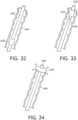
- Figures 29-31 illustrate an example of a catheter stabilizing device.
- the catheter stabilizing device 610 can comprise a flexible stabilizer 630 that is disposed radially about the catheter 620.
- the stabilizer 630 can be located on the catheter and/or on the sleeve.
- the stabilizer 630 can be made of a flexible material, for example silicon, foam, polymer, shape memory material, etc.
- the stabilizer 630 can comprise perforations 632 that are circular (see Figure 30 ) or triangular (see Figure 31 ) or another shape, which allow fluid to enter and/or exit the patient's vasculature.
- the perforations of the stabilizer can be various other shapes and sizes as needed based on the location of the catheter 620 in the patient and the vasculature that is being used for stabilization.
- the catheter stabilizing device 610 can be advanced through the vasculature 640 of the patient.
- the catheter 620 can be first introduced through the vasculature 640 of the patient.
- the stabilizer 630 can be moved distally over the catheter 620 until it reaches the opening of the vasculature 640, such as the opening of the inferior vena cava IVC, or other proper position to actuate or expand.
- the stabilizer 630 then actuates or expands, extends, etc. and engages the vasculature 640 of the patient to stabilize the catheter 620 for further use.
- the catheter stabilizing device 610 can comprise a sheath 650.
- the catheter 620 and stabilizer 630 can be placed within the sheath 650, and the catheter 620, stabilizer 630, and sheath 650 can be advanced through the vasculature of the patient.
- the sheath can be removed, thereby allowing the stabilizer 630 to engage the vasculature and stabilize the catheter for further use.
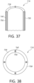
- Figures 37-40 illustrate an example of a catheter stabilizing device.
- the catheter stabilizing device 710 can comprise a stabilizer 730 that includes channels 740 that comprise wires 750.
- the wires 750 can be shape-set so that when the wires advance through the distal end of the stabilizer 730, the wires twist or turn according to the predetermined shape.
- the wires 750 when engaged, can form a variety of shapes, based on the location of the catheter 720 in the patient and the vasculature that is being used for stabilization.
- the wires 750 can, for example, extend and curl back towards the catheter 720.
- the wires 750 can be pushed out of the catheter to reach and press against a blood vessel or other vasculature structure to stabilize the catheter 720 within that structure and thereby stabilize the catheter.
- the channels 740 can comprise a variety of shapes and sizes. For example, with reference to Figures 37-40 , the channels 740 can have a substantially circular cross section.
- the stabilizer 730 can include any number of different channels. For example, with reference to Figures 37-41 , the stabilizer 730 can include four channels 740.
- the wires can be configured in a variety of ways, e.g., solid, composite, braided, woven, mesh, etc.
- Figure 41 illustrates an example of a catheter stabilizing device according to the invention.
- the catheter stabilizing device 810 comprises a stabilizer 830 that includes a shape set mesh material 840.
- the shape set mesh material 840 can be shape-set so that when it advances through the distal end 822 of the catheter 820, the mesh 840 twists, turns, or curls according to the predetermined shape.
- the shape set mesh material 840 can comprise a woven or braised wire material.
- the shape set mesh material 840 when advanced out of the catheter or tube can take a variety of shapes, based on the location of the catheter in the patient and the vasculature that is being used for stabilization.
- the shape set mesh material 840 extends and curls back towards the catheter 820.
- the shape set mesh material 840 can reach and press against a blood vessel or other vasculature structure to stabilize the catheter within that structure.
- the mesh can be braided, woven, configured in other ways, etc.
Landscapes
- Health & Medical Sciences (AREA)
- Life Sciences & Earth Sciences (AREA)
- Veterinary Medicine (AREA)
- Public Health (AREA)
- Engineering & Computer Science (AREA)
- General Health & Medical Sciences (AREA)
- Biomedical Technology (AREA)
- Heart & Thoracic Surgery (AREA)
- Animal Behavior & Ethology (AREA)
- Hematology (AREA)
- Anesthesiology (AREA)
- Pulmonology (AREA)
- Biophysics (AREA)
- Cardiology (AREA)
- Oral & Maxillofacial Surgery (AREA)
- Transplantation (AREA)
- Vascular Medicine (AREA)
- Prostheses (AREA)
- Media Introduction/Drainage Providing Device (AREA)
Claims (15)
- Katheterstabilisierungssystem, umfassend:einen Katheter (820), der ein steuerbares distales Ende (822) aufweist;einen Stabilisator (830), der mit dem Katheter (820) an einer Stelle gekoppelt oder koppelbar ist, die proximal zu dem steuerbaren distalen Ende (822) liegt; undwobei der Stabilisator (830) relativ zu dem Katheter (820) radial nach außen bewegbar ist, um den Katheter (820) während des Biegens des steuerbaren distalen Endes (822) des Katheters (820) zu stabilisieren;wobei der Stabilisator (830) ein formgeprägtes Maschenmaterial (840) umfasst; undwobei das formgeprägte Maschenmaterial (840) sich in Richtung zu dem Katheter (820) zurück einrollt, wenn es aus dem Katheter (820) herausgeschoben wird.
- Katheterstabilisierungssystem nach Anspruch 1, wobei der Stabilisator (830) expandiert und in Eingriff mit dem Gefäßsystem kommt, um den Katheter (820) zu stabilisieren.
- Katheterstabilisierungssystem nach einem der Ansprüche 1 bis 2, wobei der Katheter (820) eines oder mehrere umfasst von einer Führungshülle, einem steuerbaren Katheter (820) und einem Implantatkatheter (820).
- Katheterstabilisierungssystem nach einem der Ansprüche 1 bis 3, wobei der Stabilisator (830) in einem nicht expandierten Zustand mit dem Katheter (820) bündig ist.
- Katheterstabilisierungssystem nach einem der Ansprüche 1 bis 4, wobei der Stabilisator (830) ein oder mehrere Flügel (232) umfasst, die mit dem Katheter (820) gekoppelt sind.
- Katheterstabilisierungssystem nach Anspruch 5, wobei sich der eine oder die mehreren Flügel (232) von dem Katheter (820) radial nach außen bewegen, um den Katheter (820) zu stabilisieren.
- Katheterstabilisierungssystem nach einem der Ansprüche 1 bis 6, wobei der Stabilisator (830) einen oder mehrere mit dem Katheter (820) gekoppelte Kufen (332) umfasst.
- Katheterstabilisierungssystem nach Anspruch 7, wobei sich der eine oder die mehreren Kufen (332) radial nach außen bewegen können.
- Katheterstabilisierungssystem nach einem der Ansprüche 1 bis 8, wobei der Stabilisator (830) eine oder mehrere mit dem Katheter (820) gekoppelte Flossen (432) umfasst.
- Katheterstabilisierungssystem nach Anspruch 9, wobei sich die eine oder die mehreren Flossen (432) radial nach außen bewegen, um den Katheter (820) zu stabilisieren.
- Katheterstabilisierungssystem nach einem der Ansprüche 1 bis 10, wobei der Stabilisator (830) ein oder mehrere aufpumpbare Elemente (532) umfasst, die mit dem Katheter (820) gekoppelt sind.
- Katheterstabilisierungssystem nach Anspruch 11, wobei das eine oder die mehreren aufpumpbaren Elemente (532) beim Aufpumpen radial nach außen expandieren, um den Katheter (820) zu stabilisieren.
- Katheterstabilisierungssystem nach einem der Ansprüche 1 bis 12, wobei der Stabilisator (830) einen Kanal (740) und einen formgeprägten Draht (750) innerhalb des Kanals (740) umfasst.
- Katheterstabilisierungssystem nach Anspruch 13, wobei sich der formgeprägte Draht (750) in Richtung zu dem Katheter (820) zurück einrollt, wenn er aus dem Kanal (740) gedrückt wird.
- Katheterstabilisierungssystem nach einem der Ansprüche 1 bis 14, das ferner eine Vorrichtung (80) zur Klappenreparatur oder zum Klappenersatz umfasst, die dazu konfiguriert ist, mittels des Katheters (820) einer nativen Herzklappe zugeführt zu werden;
wobei die Vorrichtung (80) zur Klappenreparatur oder zum Klappenersatz vorzugsweise wenigstens eines umfasst von einer Klappenreparaturvorrichtung, einer Klappenersatzvorrichtung, einem Annuloplastiesystem, einer Annuloplastiestruktur, einem Annuloplastiering und einer Andockstation.
Priority Applications (1)
| Application Number | Priority Date | Filing Date | Title |
|---|---|---|---|
| EP25157210.3A EP4582057A3 (de) | 2021-04-22 | 2022-04-10 | Katheterstabilisierungsvorrichtungen |
Applications Claiming Priority (2)
| Application Number | Priority Date | Filing Date | Title |
|---|---|---|---|
| US202163178447P | 2021-04-22 | 2021-04-22 | |
| PCT/IB2022/053342 WO2022224071A1 (en) | 2021-04-22 | 2022-04-10 | Catheter stabilization devices |
Related Child Applications (1)
| Application Number | Title | Priority Date | Filing Date |
|---|---|---|---|
| EP25157210.3A Division EP4582057A3 (de) | 2021-04-22 | 2022-04-10 | Katheterstabilisierungsvorrichtungen |
Publications (2)
| Publication Number | Publication Date |
|---|---|
| EP4326196A1 EP4326196A1 (de) | 2024-02-28 |
| EP4326196B1 true EP4326196B1 (de) | 2025-02-12 |
Family
ID=81653523
Family Applications (2)
| Application Number | Title | Priority Date | Filing Date |
|---|---|---|---|
| EP22723473.9A Active EP4326196B1 (de) | 2021-04-22 | 2022-04-10 | Katheterstabilisierungsvorrichtungen |
| EP25157210.3A Pending EP4582057A3 (de) | 2021-04-22 | 2022-04-10 | Katheterstabilisierungsvorrichtungen |
Family Applications After (1)
| Application Number | Title | Priority Date | Filing Date |
|---|---|---|---|
| EP25157210.3A Pending EP4582057A3 (de) | 2021-04-22 | 2022-04-10 | Katheterstabilisierungsvorrichtungen |
Country Status (4)
| Country | Link |
|---|---|
| US (1) | US20240050704A1 (de) |
| EP (2) | EP4326196B1 (de) |
| CN (1) | CN117241760A (de) |
| WO (1) | WO2022224071A1 (de) |
Families Citing this family (42)
| Publication number | Priority date | Publication date | Assignee | Title |
|---|---|---|---|---|
| US8333777B2 (en) | 2005-04-22 | 2012-12-18 | Benvenue Medical, Inc. | Catheter-based tissue remodeling devices and methods |
| US11660190B2 (en) | 2007-03-13 | 2023-05-30 | Edwards Lifesciences Corporation | Tissue anchors, systems and methods, and devices |
| US10517719B2 (en) | 2008-12-22 | 2019-12-31 | Valtech Cardio, Ltd. | Implantation of repair devices in the heart |
| US8911494B2 (en) | 2009-05-04 | 2014-12-16 | Valtech Cardio, Ltd. | Deployment techniques for annuloplasty ring |
| US8715342B2 (en) | 2009-05-07 | 2014-05-06 | Valtech Cardio, Ltd. | Annuloplasty ring with intra-ring anchoring |
| WO2010073246A2 (en) | 2008-12-22 | 2010-07-01 | Valtech Cardio, Ltd. | Adjustable annuloplasty devices and adjustment mechanisms therefor |
| US9968452B2 (en) | 2009-05-04 | 2018-05-15 | Valtech Cardio, Ltd. | Annuloplasty ring delivery cathethers |
| US12485010B2 (en) | 2009-05-07 | 2025-12-02 | Edwards Lifesciences Innovation (Israel) Ltd. | Multiple anchor delivery tool |
| US10098737B2 (en) | 2009-10-29 | 2018-10-16 | Valtech Cardio, Ltd. | Tissue anchor for annuloplasty device |
| US10792152B2 (en) | 2011-06-23 | 2020-10-06 | Valtech Cardio, Ltd. | Closed band for percutaneous annuloplasty |
| EP3725269A1 (de) | 2011-06-23 | 2020-10-21 | Valtech Cardio, Ltd. | Verschlusselement zur verwendung mit einer annuloplastiestruktur |
| US8858623B2 (en) | 2011-11-04 | 2014-10-14 | Valtech Cardio, Ltd. | Implant having multiple rotational assemblies |
| EP3970627B1 (de) | 2011-11-08 | 2023-12-20 | Edwards Lifesciences Innovation (Israel) Ltd. | Gesteuerte lenkfunktionalität für ein implantatabgabewerkzeug |
| WO2013088327A1 (en) | 2011-12-12 | 2013-06-20 | David Alon | Heart valve repair device |
| EP2911593B1 (de) | 2012-10-23 | 2020-03-25 | Valtech Cardio, Ltd. | Perkutane gewebeankertechniken |
| US9949828B2 (en) | 2012-10-23 | 2018-04-24 | Valtech Cardio, Ltd. | Controlled steering functionality for implant-delivery tool |
| WO2014134183A1 (en) | 2013-02-26 | 2014-09-04 | Mitralign, Inc. | Devices and methods for percutaneous tricuspid valve repair |
| US10449333B2 (en) | 2013-03-14 | 2019-10-22 | Valtech Cardio, Ltd. | Guidewire feeder |
| US9724195B2 (en) | 2013-03-15 | 2017-08-08 | Mitralign, Inc. | Translation catheters and systems |
| US10070857B2 (en) | 2013-08-31 | 2018-09-11 | Mitralign, Inc. | Devices and methods for locating and implanting tissue anchors at mitral valve commissure |
| US10299793B2 (en) | 2013-10-23 | 2019-05-28 | Valtech Cardio, Ltd. | Anchor magazine |
| SG11201708397PA (en) | 2015-04-30 | 2017-11-29 | Valtech Cardio Ltd | Annuloplasty technologies |
| EP3397207B1 (de) | 2015-12-30 | 2026-04-01 | Edwards Lifesciences Corporation | System zur reduzierung von triskupidalklappenregurgitation |
| GB201611910D0 (en) | 2016-07-08 | 2016-08-24 | Valtech Cardio Ltd | Adjustable annuloplasty device with alternating peaks and troughs |
| US11045627B2 (en) | 2017-04-18 | 2021-06-29 | Edwards Lifesciences Corporation | Catheter system with linear actuation control mechanism |
| US10835221B2 (en) | 2017-11-02 | 2020-11-17 | Valtech Cardio, Ltd. | Implant-cinching devices and systems |
| US11135062B2 (en) | 2017-11-20 | 2021-10-05 | Valtech Cardio Ltd. | Cinching of dilated heart muscle |
| WO2019145947A1 (en) | 2018-01-24 | 2019-08-01 | Valtech Cardio, Ltd. | Contraction of an annuloplasty structure |
| EP3743014B1 (de) | 2018-01-26 | 2023-07-19 | Edwards Lifesciences Innovation (Israel) Ltd. | Techniken zur erleichterung von herzklappen-tethering und sehnenaustausch |
| CN120000269A (zh) | 2018-07-12 | 2025-05-16 | 爱德华兹生命科学创新(以色列)有限公司 | 瓣环成形系统及其锁定工具 |
| AU2020284630A1 (en) | 2019-05-29 | 2021-11-18 | Edwards Lifesciences Innovation (Israel) Ltd. | Tissue anchor handling systems and methods |
| US12502167B2 (en) | 2019-07-16 | 2025-12-23 | Edwards Lifesciences Corporation | Tissue remodeling systems and methods |
| CA3141295A1 (en) | 2019-07-23 | 2021-01-28 | Valtech Cardio, Ltd. | Contraction of an annuloplasty structure |
| WO2021038560A1 (en) | 2019-08-28 | 2021-03-04 | Valtech Cardio, Ltd. | Low-profile steerable catheter |
| EP4021350B1 (de) | 2019-08-30 | 2024-12-18 | Edwards Lifesciences Innovation (Israel) Ltd. | Ankerkanalspitze |
| KR20220066398A (ko) | 2019-09-25 | 2022-05-24 | 카디악 임플란츠 엘엘씨 | 심장 판막 고리 감소 시스템 |
| WO2021071682A1 (en) * | 2019-10-09 | 2021-04-15 | Edwards Lifesciences Corporation | Heart valve sealing devices and delivery devices therefor |
| KR20220122966A (ko) | 2019-10-29 | 2022-09-05 | 에드워즈 라이프사이언시스 이노베이션 (이스라엘) 리미티드 | 고리 성형술 및 조직 앵커 기술 |
| EP4096529B1 (de) | 2020-03-23 | 2025-05-07 | Edwards Lifesciences Innovation (Israel) Ltd. | Selbstsichernde winde |
| JP2023527304A (ja) | 2020-05-20 | 2023-06-28 | カーディアック・インプランツ・エルエルシー | 心臓弁輪に打ち込まれるアンカそれぞれを独立的に制御することによる心臓弁輪の直径の減少 |
| WO2024156589A1 (en) * | 2023-01-26 | 2024-08-02 | Koninklijke Philips N.V. | Intraluminal imaging catheter with expandable structure for imaging element stabilization |
| US20250161627A1 (en) | 2023-10-27 | 2025-05-22 | Nowwell Flow Technology AS | Catheter |
Family Cites Families (7)
| Publication number | Priority date | Publication date | Assignee | Title |
|---|---|---|---|---|
| US20060058775A1 (en) * | 1991-07-16 | 2006-03-16 | Stevens John H | System and methods for performing endovascular procedures |
| US20060069429A1 (en) * | 2001-04-24 | 2006-03-30 | Spence Paul A | Tissue fastening systems and methods utilizing magnetic guidance |
| US8911494B2 (en) | 2009-05-04 | 2014-12-16 | Valtech Cardio, Ltd. | Deployment techniques for annuloplasty ring |
| US10478297B2 (en) * | 2015-01-27 | 2019-11-19 | Medtronic Vascular, Inc. | Delivery system having an integral centering mechanism for positioning a valve prosthesis in situ |
| CN210673408U (zh) * | 2018-01-03 | 2020-06-05 | 杭州启明医疗器械股份有限公司 | 调弯鞘管以及可调弯介入瓣膜输送系统 |
| KR102180828B1 (ko) | 2018-09-21 | 2020-11-19 | 주식회사 포스코 | 도금량 제어 장치 및 도금량 제어 방법 |
| CA3118722A1 (en) | 2018-11-20 | 2020-05-28 | Edwards Lifesciences Corporation | Deployment tools and methods for delivering a device to a native heart valve |
-
2022
- 2022-04-10 EP EP22723473.9A patent/EP4326196B1/de active Active
- 2022-04-10 CN CN202280029840.3A patent/CN117241760A/zh active Pending
- 2022-04-10 WO PCT/IB2022/053342 patent/WO2022224071A1/en not_active Ceased
- 2022-04-10 EP EP25157210.3A patent/EP4582057A3/de active Pending
-
2023
- 2023-10-20 US US18/491,737 patent/US20240050704A1/en active Pending
Also Published As
| Publication number | Publication date |
|---|---|
| EP4582057A3 (de) | 2025-08-27 |
| US20240050704A1 (en) | 2024-02-15 |
| CN117241760A (zh) | 2023-12-15 |
| EP4582057A2 (de) | 2025-07-09 |
| EP4326196A1 (de) | 2024-02-28 |
| WO2022224071A1 (en) | 2022-10-27 |
Similar Documents
| Publication | Publication Date | Title |
|---|---|---|
| EP4326196B1 (de) | Katheterstabilisierungsvorrichtungen | |
| US12274617B2 (en) | Devices, systems and methods for accurate positioning of a prosthetic valve | |
| US12419743B2 (en) | Prosthetic cardiac valve devices, systems, and methods | |
| US20240245511A1 (en) | Delivery system with adaptable nosecone | |
| US11832829B2 (en) | Stabilization of a transseptal delivery device | |
| US11083581B2 (en) | Expandable heart valve coaptation device | |
| US11833034B2 (en) | Prosthetic cardiac valve devices, systems, and methods | |
| CN102256568B (zh) | 快速连接的人工心脏瓣膜和方法 | |
| US10456256B2 (en) | Heart valve repair | |
| JP5759949B2 (ja) | プロテーゼの経皮的送達のための送達ツール | |
| US11833044B2 (en) | Delivery systems having a temporary valve and methods of use | |
| EP3773335A1 (de) | Mitralklappenspacervorrichtung | |
| JP2020501633A (ja) | 原位置で腱索を管理するための一体型変位構成要素を有する弁送達システム、及びその使用方法 | |
| US20240341951A1 (en) | Prosthetic cardiac valve devices, systems, and methods | |
| US20230270551A1 (en) | Catheters for implants and medical procedures and methods of use thereof |
Legal Events
| Date | Code | Title | Description |
|---|---|---|---|
| STAA | Information on the status of an ep patent application or granted ep patent |
Free format text: STATUS: UNKNOWN |
|
| STAA | Information on the status of an ep patent application or granted ep patent |
Free format text: STATUS: THE INTERNATIONAL PUBLICATION HAS BEEN MADE |
|
| PUAI | Public reference made under article 153(3) epc to a published international application that has entered the european phase |
Free format text: ORIGINAL CODE: 0009012 |
|
| STAA | Information on the status of an ep patent application or granted ep patent |
Free format text: STATUS: REQUEST FOR EXAMINATION WAS MADE |
|
| 17P | Request for examination filed |
Effective date: 20231122 |
|
| AK | Designated contracting states |
Kind code of ref document: A1 Designated state(s): AL AT BE BG CH CY CZ DE DK EE ES FI FR GB GR HR HU IE IS IT LI LT LU LV MC MK MT NL NO PL PT RO RS SE SI SK SM TR |
|
| P01 | Opt-out of the competence of the unified patent court (upc) registered |
Effective date: 20240304 |
|
| DAV | Request for validation of the european patent (deleted) | ||
| DAX | Request for extension of the european patent (deleted) | ||
| GRAP | Despatch of communication of intention to grant a patent |
Free format text: ORIGINAL CODE: EPIDOSNIGR1 |
|
| STAA | Information on the status of an ep patent application or granted ep patent |
Free format text: STATUS: GRANT OF PATENT IS INTENDED |
|
| INTG | Intention to grant announced |
Effective date: 20240903 |
|
| GRAS | Grant fee paid |
Free format text: ORIGINAL CODE: EPIDOSNIGR3 |
|
| GRAA | (expected) grant |
Free format text: ORIGINAL CODE: 0009210 |
|
| STAA | Information on the status of an ep patent application or granted ep patent |
Free format text: STATUS: THE PATENT HAS BEEN GRANTED |
|
| AK | Designated contracting states |
Kind code of ref document: B1 Designated state(s): AL AT BE BG CH CY CZ DE DK EE ES FI FR GB GR HR HU IE IS IT LI LT LU LV MC MK MT NL NO PL PT RO RS SE SI SK SM TR |
|
| REG | Reference to a national code |
Ref country code: GB Ref legal event code: FG4D |
|
| REG | Reference to a national code |
Ref country code: CH Ref legal event code: EP |
|
| REG | Reference to a national code |
Ref country code: DE Ref legal event code: R096 Ref document number: 602022010546 Country of ref document: DE |
|
| REG | Reference to a national code |
Ref country code: IE Ref legal event code: FG4D |
|
| REG | Reference to a national code |
Ref country code: NL Ref legal event code: MP Effective date: 20250212 |
|
| PG25 | Lapsed in a contracting state [announced via postgrant information from national office to epo] |
Ref country code: RS Free format text: LAPSE BECAUSE OF FAILURE TO SUBMIT A TRANSLATION OF THE DESCRIPTION OR TO PAY THE FEE WITHIN THE PRESCRIBED TIME-LIMIT Effective date: 20250512 |
|
| PG25 | Lapsed in a contracting state [announced via postgrant information from national office to epo] |
Ref country code: FI Free format text: LAPSE BECAUSE OF FAILURE TO SUBMIT A TRANSLATION OF THE DESCRIPTION OR TO PAY THE FEE WITHIN THE PRESCRIBED TIME-LIMIT Effective date: 20250212 |
|
| PG25 | Lapsed in a contracting state [announced via postgrant information from national office to epo] |
Ref country code: PL Free format text: LAPSE BECAUSE OF FAILURE TO SUBMIT A TRANSLATION OF THE DESCRIPTION OR TO PAY THE FEE WITHIN THE PRESCRIBED TIME-LIMIT Effective date: 20250212 |
|
| PGFP | Annual fee paid to national office [announced via postgrant information from national office to epo] |
Ref country code: DE Payment date: 20250211 Year of fee payment: 4 |
|
| PG25 | Lapsed in a contracting state [announced via postgrant information from national office to epo] |
Ref country code: ES Free format text: LAPSE BECAUSE OF FAILURE TO SUBMIT A TRANSLATION OF THE DESCRIPTION OR TO PAY THE FEE WITHIN THE PRESCRIBED TIME-LIMIT Effective date: 20250212 |
|
| REG | Reference to a national code |
Ref country code: LT Ref legal event code: MG9D |
|
| PG25 | Lapsed in a contracting state [announced via postgrant information from national office to epo] |
Ref country code: NO Free format text: LAPSE BECAUSE OF FAILURE TO SUBMIT A TRANSLATION OF THE DESCRIPTION OR TO PAY THE FEE WITHIN THE PRESCRIBED TIME-LIMIT Effective date: 20250512 Ref country code: IS Free format text: LAPSE BECAUSE OF FAILURE TO SUBMIT A TRANSLATION OF THE DESCRIPTION OR TO PAY THE FEE WITHIN THE PRESCRIBED TIME-LIMIT Effective date: 20250612 |
|
| PG25 | Lapsed in a contracting state [announced via postgrant information from national office to epo] |
Ref country code: NL Free format text: LAPSE BECAUSE OF FAILURE TO SUBMIT A TRANSLATION OF THE DESCRIPTION OR TO PAY THE FEE WITHIN THE PRESCRIBED TIME-LIMIT Effective date: 20250212 |
|
| PG25 | Lapsed in a contracting state [announced via postgrant information from national office to epo] |
Ref country code: HR Free format text: LAPSE BECAUSE OF FAILURE TO SUBMIT A TRANSLATION OF THE DESCRIPTION OR TO PAY THE FEE WITHIN THE PRESCRIBED TIME-LIMIT Effective date: 20250212 |
|
| PG25 | Lapsed in a contracting state [announced via postgrant information from national office to epo] |
Ref country code: PT Free format text: LAPSE BECAUSE OF FAILURE TO SUBMIT A TRANSLATION OF THE DESCRIPTION OR TO PAY THE FEE WITHIN THE PRESCRIBED TIME-LIMIT Effective date: 20250612 Ref country code: LV Free format text: LAPSE BECAUSE OF FAILURE TO SUBMIT A TRANSLATION OF THE DESCRIPTION OR TO PAY THE FEE WITHIN THE PRESCRIBED TIME-LIMIT Effective date: 20250212 |
|
| PG25 | Lapsed in a contracting state [announced via postgrant information from national office to epo] |
Ref country code: BG Free format text: LAPSE BECAUSE OF FAILURE TO SUBMIT A TRANSLATION OF THE DESCRIPTION OR TO PAY THE FEE WITHIN THE PRESCRIBED TIME-LIMIT Effective date: 20250212 Ref country code: GR Free format text: LAPSE BECAUSE OF FAILURE TO SUBMIT A TRANSLATION OF THE DESCRIPTION OR TO PAY THE FEE WITHIN THE PRESCRIBED TIME-LIMIT Effective date: 20250513 |
|
| REG | Reference to a national code |
Ref country code: AT Ref legal event code: MK05 Ref document number: 1765372 Country of ref document: AT Kind code of ref document: T Effective date: 20250212 |
|
| PG25 | Lapsed in a contracting state [announced via postgrant information from national office to epo] |
Ref country code: SE Free format text: LAPSE BECAUSE OF FAILURE TO SUBMIT A TRANSLATION OF THE DESCRIPTION OR TO PAY THE FEE WITHIN THE PRESCRIBED TIME-LIMIT Effective date: 20250212 |
|
| PG25 | Lapsed in a contracting state [announced via postgrant information from national office to epo] |
Ref country code: SM Free format text: LAPSE BECAUSE OF FAILURE TO SUBMIT A TRANSLATION OF THE DESCRIPTION OR TO PAY THE FEE WITHIN THE PRESCRIBED TIME-LIMIT Effective date: 20250212 |
|
| PG25 | Lapsed in a contracting state [announced via postgrant information from national office to epo] |
Ref country code: DK Free format text: LAPSE BECAUSE OF FAILURE TO SUBMIT A TRANSLATION OF THE DESCRIPTION OR TO PAY THE FEE WITHIN THE PRESCRIBED TIME-LIMIT Effective date: 20250212 |
|
| PG25 | Lapsed in a contracting state [announced via postgrant information from national office to epo] |
Ref country code: IT Free format text: LAPSE BECAUSE OF FAILURE TO SUBMIT A TRANSLATION OF THE DESCRIPTION OR TO PAY THE FEE WITHIN THE PRESCRIBED TIME-LIMIT Effective date: 20250212 |
|
| PG25 | Lapsed in a contracting state [announced via postgrant information from national office to epo] |
Ref country code: AT Free format text: LAPSE BECAUSE OF FAILURE TO SUBMIT A TRANSLATION OF THE DESCRIPTION OR TO PAY THE FEE WITHIN THE PRESCRIBED TIME-LIMIT Effective date: 20250212 |
|
| PG25 | Lapsed in a contracting state [announced via postgrant information from national office to epo] |
Ref country code: EE Free format text: LAPSE BECAUSE OF FAILURE TO SUBMIT A TRANSLATION OF THE DESCRIPTION OR TO PAY THE FEE WITHIN THE PRESCRIBED TIME-LIMIT Effective date: 20250212 Ref country code: CZ Free format text: LAPSE BECAUSE OF FAILURE TO SUBMIT A TRANSLATION OF THE DESCRIPTION OR TO PAY THE FEE WITHIN THE PRESCRIBED TIME-LIMIT Effective date: 20250212 |
|
| PG25 | Lapsed in a contracting state [announced via postgrant information from national office to epo] |
Ref country code: RO Free format text: LAPSE BECAUSE OF FAILURE TO SUBMIT A TRANSLATION OF THE DESCRIPTION OR TO PAY THE FEE WITHIN THE PRESCRIBED TIME-LIMIT Effective date: 20250212 |
|
| PG25 | Lapsed in a contracting state [announced via postgrant information from national office to epo] |
Ref country code: SK Free format text: LAPSE BECAUSE OF FAILURE TO SUBMIT A TRANSLATION OF THE DESCRIPTION OR TO PAY THE FEE WITHIN THE PRESCRIBED TIME-LIMIT Effective date: 20250212 |
|
| REG | Reference to a national code |
Ref country code: DE Ref legal event code: R097 Ref document number: 602022010546 Country of ref document: DE |
|
| REG | Reference to a national code |
Ref country code: CH Ref legal event code: H13 Free format text: ST27 STATUS EVENT CODE: U-0-0-H10-H13 (AS PROVIDED BY THE NATIONAL OFFICE) Effective date: 20251125 |
|
| PG25 | Lapsed in a contracting state [announced via postgrant information from national office to epo] |
Ref country code: LU Free format text: LAPSE BECAUSE OF NON-PAYMENT OF DUE FEES Effective date: 20250410 |
|
| PLBE | No opposition filed within time limit |
Free format text: ORIGINAL CODE: 0009261 |
|
| STAA | Information on the status of an ep patent application or granted ep patent |
Free format text: STATUS: NO OPPOSITION FILED WITHIN TIME LIMIT |
|
| PG25 | Lapsed in a contracting state [announced via postgrant information from national office to epo] |
Ref country code: MC Free format text: LAPSE BECAUSE OF FAILURE TO SUBMIT A TRANSLATION OF THE DESCRIPTION OR TO PAY THE FEE WITHIN THE PRESCRIBED TIME-LIMIT Effective date: 20250212 |
|
| REG | Reference to a national code |
Ref country code: BE Ref legal event code: MM Effective date: 20250430 |
|
| PG25 | Lapsed in a contracting state [announced via postgrant information from national office to epo] |
Ref country code: FR Free format text: LAPSE BECAUSE OF NON-PAYMENT OF DUE FEES Effective date: 20250412 |
|
| PG25 | Lapsed in a contracting state [announced via postgrant information from national office to epo] |
Ref country code: BE Free format text: LAPSE BECAUSE OF NON-PAYMENT OF DUE FEES Effective date: 20250430 |
|
| PG25 | Lapsed in a contracting state [announced via postgrant information from national office to epo] |
Ref country code: CH Free format text: LAPSE BECAUSE OF NON-PAYMENT OF DUE FEES Effective date: 20250430 |
|
| 26N | No opposition filed |
Effective date: 20251113 |
|
| PGFP | Annual fee paid to national office [announced via postgrant information from national office to epo] |
Ref country code: GB Payment date: 20260223 Year of fee payment: 5 |
|
| PG25 | Lapsed in a contracting state [announced via postgrant information from national office to epo] |
Ref country code: IE Free format text: LAPSE BECAUSE OF NON-PAYMENT OF DUE FEES Effective date: 20250410 |