EP4327696B1 - Ensemble rail coulissant - Google Patents
Ensemble rail coulissant Download PDFInfo
- Publication number
- EP4327696B1 EP4327696B1 EP23153259.9A EP23153259A EP4327696B1 EP 4327696 B1 EP4327696 B1 EP 4327696B1 EP 23153259 A EP23153259 A EP 23153259A EP 4327696 B1 EP4327696 B1 EP 4327696B1
- Authority
- EP
- European Patent Office
- Prior art keywords
- rail
- elastic
- slide
- assisting device
- elastic member
- Prior art date
- Legal status (The legal status is an assumption and is not a legal conclusion. Google has not performed a legal analysis and makes no representation as to the accuracy of the status listed.)
- Active
Links
Images



Classifications
-
- A—HUMAN NECESSITIES
- A47—FURNITURE; DOMESTIC ARTICLES OR APPLIANCES; COFFEE MILLS; SPICE MILLS; SUCTION CLEANERS IN GENERAL
- A47B—TABLES; DESKS; OFFICE FURNITURE; CABINETS; DRAWERS; GENERAL DETAILS OF FURNITURE
- A47B88/00—Drawers for tables, cabinets or like furniture; Guides for drawers
- A47B88/50—Safety devices or the like for drawers
- A47B88/57—Safety devices or the like for drawers preventing complete withdrawal of the drawer
-
- A—HUMAN NECESSITIES
- A47—FURNITURE; DOMESTIC ARTICLES OR APPLIANCES; COFFEE MILLS; SPICE MILLS; SUCTION CLEANERS IN GENERAL
- A47B—TABLES; DESKS; OFFICE FURNITURE; CABINETS; DRAWERS; GENERAL DETAILS OF FURNITURE
- A47B88/00—Drawers for tables, cabinets or like furniture; Guides for drawers
- A47B88/40—Sliding drawers; Slides or guides therefor
- A47B88/44—Sequencing or synchronisation of drawer slides or functional units
- A47B88/447—Simultaneous movement of rails within drawer slides, i.e. with a coordination of movement with all rail elements moving at the same time
Definitions
- the present invention is related to a slide rail assembly.
- US patent number US 9,980,566 B2 discloses a slide rail assembly, which comprises a first rail, a second rail, a blocking base, a ball retainer and a blocking member.
- the second rail is movable relative to the first rail.
- the blocking base is arranged on the first rail and has a limiting part.
- the ball retainer is configured to facilitate movement between the second rail and the first rail.
- the ball retainer has a contact part.
- the contact part of the ball retainer is a fixed portion (non-movable portion).
- the blocking member is configured to be operatively moved relative to the second rail from a first state to a second state.
- the blocking member When the blocking member is in the first state, the blocking member is configured to push the contact part of the ball retainer to move the ball retainer in response to a movement of the second rail along an opening direction until the blocking member abuts against the limiting part of the blocking base. Meanwhile, an engagement feature of the ball retainer is engaged with an elastic arm on the blocking base of the first rail, such that the ball retainer can be temporarily held and stopped at a predetermined position, and the contact part of the ball retainer and the limiting part of the blocking base are separated from each other.
- the present invention aims at providing a slide rail assembly capable of forcibly driving a slide assisting device to move to a predetermined position.
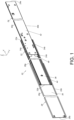
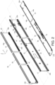
- a slide rail assembly 20 comprises a first rail 22 and a second rail 24 according to an embodiment of the present invention.
- the slide rail assembly 20 further comprises a third rail 26.
- the first rail 22 is movably mounted between the third rail 26 and the second rail 24, and the first rail 22 is configured to extend a traveling distance of the second rail 24 relative to the third rail 26.
- the third rail 26 (such as an outer rail), the first rail 22 (such as a middle rail) and the second rail 24 (such as an inner rail) are longitudinally movable relative to each other.
- the X axis is a longitudinal direction (or a length direction) of the slide rail assembly 20
- the Y axis is a transverse direction (or a lateral direction) of the slide rail assembly 20
- the Z axis is a vertical direction (or a height direction) of the slide rail assembly 20.
- the third rail 26 comprises a first wall 28a, a second wall 28b and a longitudinal wall 30 connected between the first wall 28a and the second wall 28b of the third rail 26.
- a passage 32 is defined by the first wall 28a, the second wall 28b and the longitudinal wall 30 of the third rail 26 in order to accommodate the first rail 22.
- the third rail 26 has a front part 26a and a rear part 26b.
- the first rail 22 comprises a first wall 34a, a second wall 34b and a longitudinal wall 36 connected between the first wall 34a and the second wall 34b of the first rail 22.
- a passage 38 is defined by the first wall 34a, the second wall 34b and the longitudinal wall 36 of the first rail 22 in order to accommodate the second rail 24.
- the first rail 22 has a front part 22a and a rear part 22b.
- the second rail 24 comprises a first wall 40a, a second wall 40b and a longitudinal wall 42 connected between the first wall 40a and the second wall 40b of the second rail 24.
- the second rail 24 has a front part 24a and a rear part 24b.
- the slide rail assembly 20 further comprises a slide assisting device 46 movably mounted between the first rail 22 and the second rail 24.
- the slide assisting device 46 is arranged in the passage 38 of the first rail 22, and the slide assisting device 46 comprises a plurality of rolling members 48, such as rolling balls (please refer to FIG. 3 ), in order to improve smoothness of relative movement between the second rail 24 and the first rail 22.
- the slide assisting device 46 comprises a main body 33.
- the plurality of rolling members 48 are arranged on the main body 33 and configured to support the first rail 22 and the second rail 24.
- the first rail 22 comprises a blocking feature 50 and is formed with a predetermined space 52.
- the blocking feature 50 is located inside the passage 38 of the first rail 22.
- the blocking feature 50 such as a protrusion part, is transversely (or laterally) protruded relative to the longitudinal wall 36 of the first rail 22, but the present invention is not limited thereto.
- the blocking feature 50 is located adjacent to the front part 22a of the first rail 22.
- the longitudinal wall 36 of the first rail 22 is formed with the predetermined space 52.
- the longitudinal wall 36 of the first rail 22 comprises a groove to provide the predetermined space 52.
- the predetermined space 52 is provided by an opening, but the present invention is not limited thereto.
- the predetermined space 52 is laterally communicated with a first side L1 and a second side L2 of the longitudinal wall 36 of the first rail 22.
- the first side L1 is opposite to the second side L2.
- the first side L1 of the longitudinal wall 36 of the first rail 22 faces the longitudinal wall 30 of the third rail 26, and the second side L2 of the longitudinal wall 36 of the first rail 22 faces the longitudinal wall 42 of the second rail 24 (please also refer to FIG. 1 ).
- the slide assisting device 46 is located inside the passage 38 of the first rail 22.
- the main body 33 of the slide assisting device 46 comprises a first part 54a, a second part 54b and a longitudinal part 56 connected between the first part 54a and the second part 54b of the main body 33.
- the plurality of rolling members 48 are arranged on the first part 54a and the second part 54b of the main body 33 (due to the viewing angle, FIG. 3 only shows the rolling members 48 on the second part 54b of the main body 33 without showing the rolling members 48 on the first part 54a of the main body 33).
- the first part 54a, the second part 54b and the longitudinal part 56 respectively correspond to the first wall 34a, the second wall 34b and the longitudinal wall 36 of the first rail 22.
- the slide rail assembly 20 further comprises an elastic member 58 arranged on the main body 33 of the slide assisting device 46.
- the elastic member 58 and the main body 33 are two independent components, but the present invention is not limited thereto.
- the elastic member 58 is arranged on the longitudinal part 56 of the main body 33.
- the elastic member 58 comprises a connecting part 60, an elastic part 62 and a predetermined part 64.
- the connecting part 60 of the elastic member 58 is connected (such as fixedly connected) to the longitudinal part 56 of the main body 33.
- the elastic part 62 is extended from the connecting part 60, and the predetermined part 64 is located on the elastic part 62.
- the predetermined part 64 (such as a protrusion) is transversely protruded relative to the elastic part 62, but the present invention is not limited thereto.
- the elastic part 62 is configured to be supported by the longitudinal wall 36 of the first rail 22 to hold the elastic member 58 to be in an initial state K1 to accumulate an elastic force F.
- the longitudinal part 56 of the main body 33 is formed with a space 65 (such as an opening) communicating with two sides of the longitudinal part 56 of the main body 33.
- the elastic part 62 transversely penetrates through the space 65, so that the elastic part 62 is supported by the longitudinal wall 36 of the first rail 22 to hold the elastic member 58 to be in the initial state K1 and accumulate the elastic force F.
- the slide rail assembly 20 further comprises an engaging member 66 arranged on the first rail 22.
- the engaging member 66 comprises a fixed part 68 and an elastic arm 70.
- the fixed part 68 is fixed to the longitudinal wall 36 of the first rail 22.
- the elastic arm 70 is extended from the fixed part 68, and the elastic arm 70 comprises a fastening section 72.
- the main body 33 of the slide assisting device 46 further comprises a fastening part 74 configured to interact with the fastening section 72.
- the fastening part 74 is located adjacent to a front end of the main body 33, but the present invention is not limited thereto.
- the slide rail assembly 20 further comprises a working member 76 arranged on the second rail 24. Furthermore, the working member 76 is movably mounted to the second rail 24. In the present embodiment, the working member 76 is pivotally connected to the second rail 24 through a shaft member 78.
- the slide rail assembly 20 further comprises an operating member 80 and an auxiliary base 82.
- the operating member 80 is configured to be operated to move the working member 76.
- the operating member 80 is movably mounted to the second rail 24.
- the operating member 80 is movable relative to the second rail 24 along the length direction of the second rail 24.
- the second rail 24 comprises at least one holding feature 84 configured to support the operating member 80 in order to improve stability when the operating member 80 is operated to move.
- the operating member 80 comprises an operating part 86a, a driving part 86b and an extension part 86c connected between the operating part 86a and the driving part 86b.
- the auxiliary base 82 is arranged on the second rail 24, and the auxiliary base 82 is configured to provide an elastic force to the working member 76.
- the auxiliary base 82 comprises an elastic section 88 configured to provide the elastic force to the working member 76.
- the working member 76 is held in a first state S1 in response to the elastic force of the elastic section 88.
- the first rail 22 is extended relative to the third rail 26, and the front part 22a of the first rail 22 is extended beyond the front part 26a of the third rail 26.
- the working member 76 is held in the first state S1 in response to the elastic force of the elastic section 88 of the auxiliary base 82.
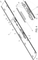
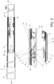
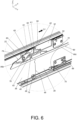
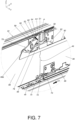
- the working member 76 in the first state S1 is configured to contact the predetermined part 64 of the elastic member 58 in the initial state K1 (as shown in FIG. 5 and FIG. 6 ), in order to forcibly drive the slide assisting device 46 to move along the opening direction D1 to a predetermined position P (as shown in FIG. 7 ) .
- the elastic member 58 releases the elastic force F through the predetermined space 52 of the first rail 22 (the elastic part 62 of the elastic member 58 transversely extended into the predetermined space 52 of the first rail 22) to be switched from the initial state K1 (as shown in FIG. 5 and FIG. 6 ) to a non-initial state K2 (as shown in FIG. 7 ), such that the working member 76 no longer contacts the elastic member 58.
- the working member 76 is configured to contact the predetermined part 64 on the elastic part 62 of the elastic member 58 (as shown in FIG. 5 and FIG. 6 ) in order to forcibly drive the slide assisting device 46 to move along the opening direction D1, such that the slide assisting device 46 can be ensured to be close to the front part 22a of the first rail 22.
- the first wall 40a and the second wall 40b of a predetermined section (such as a middle section and/or a rear section, but the present invention is not limited thereto) of the second rail 24 can be properly supported by the slide assisting device 46 (the rolling members 48 of the slide assisting device 46) as shown in FIG. 5 .
- the elastic part 62 of the elastic member 58 releases the elastic force F through the predetermined space 52 of the longitudinal wall 36 of the first rail 22, such that the elastic part 62 of the elastic member 58 is transversely (or laterally) moved to switch the elastic member 58 from the initial state K1 (as shown in FIG. 5 and FIG. 6 ) to the non-initial state K2 (as shown in FIG. 7 ). Therefore, the working member 76 is separated from the predetermined part 64 on the elastic part 62 of the elastic member 58, such that the working member 76 no longer contacts the predetermined part 64 on the elastic part 62 of the elastic member 58.
- the blocking feature 50 of the first rail 22 is configured to block the working member 76 in the first state S1, in order to prevent the second rail 24 from being moved from the extension position E along the opening direction D1 (as shown in FIG. 9 and FIG. 10 ).
- the slide assisting device 46 is moved (differentially moved) along with the second rail 24 along the opening direction D1 by a predetermined distance J (as shown in FIG. 8 and FIG. 9 ), such that the engaging member 66 (the fastening section 72 of the engaging member 66) is configured to engage with the slide assisting device 46 (the fastening part 74 of the slide assisting device 46) to temporarily hold the slide assisting device 46 at a position close to the front part 22a of the first rail 22 (as shown in FIG. 10 ).
- the aforementioned differential movement is a movement of the rolling members 48 of the slide assisting device 46 being driven to roll in response to the movement of the second rail 24 relative to the first rail 22, so that displacement of the slide assisting device 46 is smaller than actual displacement of the second rail 24.
- Such configuration is well known to those skilled in the art, for simplification, no further illustration is provided.
- the second rail 24 can be moved relative to the first rail 22 from the extension position E along a retraction direction D2.
- the engaging member 66 (the fastening section 72 of the engaging member 66) can be disengaged from the slide assisting device 46 (the fastening part 74 of the slide assisting device 46) through a predetermined feature 90 or a predetermine portion of the second rail 24 (such as an inclined surface or an arc surface as shown in FIG. 10 ).
- the predetermined feature 90 is configured to drive the elastic arm 70 of the engaging member 66 to deflect, in order to disengage the engaging member 66 (the fastening section 72 of the engaging member 66) from the slide assisting device 46 (the fastening part 74 of the slide assisting device 46) .
- Such configuration is well known to those skilled in the art, for simplification, no further illustration is provided.
- the rolling members 48 of the slide assisting device 46 is configured to be driven to roll in response to movement of the second rail 24 along the retraction direction D2, such that the slide assisting device 46 is moved (differentially moved) along the retraction direction D2.
- the elastic member 58 (the elastic part 62 of the elastic member 58) is configured to be moved away from the predetermined space 52 of the first rail 22 to return to the initial state K1 from the non-initial state K2.
- the operating member 80 is configured to be operated to drive the working member 76 to switch from the first state S1 (as shown in FIG. 10 ) to a second state S2 (as shown in FIG. 11 ), such that the blocking feature 50 of the first rail 22 no longer blocks the working member 76 in order to allow the second rail 24 to move from the extension position E along the opening direction D1.
- a user can apply an operating force F' to the operating part 86a of the operating member 80 to move the operating member 80 from a first operating position X1 (as shown in FIG. 10 ) to a second operating position X2 (as shown in FIG. 11 ), such that driving part 86b of the operating member 80 is configured to drive the working member 76 to rotate from the first state S1 (as shown in FIG. 10 ) to the second state S2 (as shown in FIG. 11 ) . Therefore, the blocking feature 50 of the first rail 22 no longer blocks the working member 76, so as to allow the second rail 24 to move from the extension position E along the opening direction D1 to be detached from the passage 38 of the first rail 22 (as shown in FIG. 11 ).
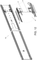
- FIG. 12 shows a first rail 200 according to another embodiment of the present invention.
- the first rail 200 is configured to have an elastic member 202 being integrated to the main body 33 of the slide assisting device 46.
- Such configuration can achieve the same technical effect as the aforementioned embodiment.
- the slide rail assembly 20 according to the embodiment of the present invention has the following technical features:
Landscapes
- Seats For Vehicles (AREA)
- Drawers Of Furniture (AREA)
- Engineering & Computer Science (AREA)
- General Engineering & Computer Science (AREA)
- Mechanical Engineering (AREA)
- Bearings For Parts Moving Linearly (AREA)
- Forklifts And Lifting Vehicles (AREA)
Claims (9)
- Ensemble de glissière (20), comprenant :un premier rail (22, 200) comprenant une caractéristique de blocage (50) et étant formé avec un espace prédéterminé (52) ;un deuxième rail (24) mobile longitudinalement par rapport au premier rail (22, 200) ;un dispositif d'assistance au glissement (46) monté mobile entre le premier rail (22, 200) et le deuxième rail (24) ;un élément élastique (58, 202) disposé sur le dispositif d'assistance au glissement (46) ; etun élément fonctionnel (76) disposé sur le deuxième rail (24) ;dans lequel, au cours d'un processus de déplacement du deuxième rail (24) par rapport au premier rail (22, 200) le long d'une direction d'ouverture, l'élément fonctionnel (76) est configuré pour contacter l'élément élastique (58, 202) dans un état initial afin d'entraîner le dispositif d'assistance au glissement (46) à se déplacer le long de la direction d'ouverture jusqu'à une position prédéterminée ;caractérisé en ce que :lorsque le dispositif d'assistance au glissement (46) se trouve dans la position prédéterminée, l'élément élastique (58, 202) est configuré pour libérer une force élastique à travers l'espace prédéterminé (52) du premier rail (22, 200) pour passer de l'état initial à un état non initial, de sorte que l'élément fonctionnel (76) ne contacte plus l'élément élastique (58, 202) dans l'état non initial, etlorsque le deuxième rail (24) est encore déplacé par rapport au premier rail (22, 200) le long de la direction d'ouverture vers une position d'extension, la caractéristique de blocage (50) du premier rail (22, 200) est configurée pour bloquer l'élément fonctionnel (76) afin d'empêcher le deuxième rail (24) d'être déplacé à partir de la position d'extension le long de la direction d'ouverture.
- Ensemble de glissière selon la revendication 1, caractérisé en ce que le premier rail (22, 200) présente une partie avant (22a) et une partie arrière (22b), et la caractéristique de blocage (50) est située adjacente à la partie avant (22a) du premier rail (22, 200) ; dans lequel le premier rail (22, 200) comprend une première paroi (34a), une deuxième paroi (34b) et une paroi longitudinale (36) reliée entre la première paroi (34a) et la deuxième paroi (34b), et un passage (38) est défini par la première paroi (34a), la deuxième paroi (34b) et la paroi longitudinale (36) du premier rail (22, 200) afin d'accueillir le deuxième rail (24) .
- Ensemble de glissière selon la revendication 2, caractérisé en ce que le dispositif d'assistance au glissement (46) est situé à l'intérieur du passage (38) du premier rail (22, 200) ; le dispositif d'assistance au glissement (46) comprend un corps principal (33) et une pluralité d'éléments roulants (48) disposés sur le corps principal (33), et la pluralité d'éléments roulants (48) sont configurés pour supporter le premier rail (22, 200) et le deuxième rail (24) ; dans lequel l'élément élastique (58, 202) est disposé sur le corps principal (33) du dispositif d'assistance au glissement (46) .
- Ensemble de glissière selon la revendication 3, caractérisé en ce que le corps principal (33) du dispositif d'assistance au glissement (46) comprend une première partie (54a), une deuxième partie (54b) et une partie longitudinale (56) reliée entre la première partie (54a) et la deuxième partie (54b) du corps principal (33), et la pluralité d'éléments roulants (48) sont disposés sur la première partie (54a) et la deuxième partie (54b) du corps principal (33).
- Ensemble de glissière selon la revendication 4, caractérisé en ce que l'élément élastique (58, 202) comprend une partie de connexion (60), une partie élastique (62) et une partie prédéterminée (64) ; la partie de connexion (60) de l'élément élastique (58, 202) est reliée à la partie longitudinale (56) du corps principal (33), la partie élastique (62) est étendue à partir de la partie de connexion (60), et la partie prédéterminée (64) est située sur la partie élastique (62) ; dans lequel la partie élastique (62) est configurée pour être supportée par la paroi longitudinale (36) du premier rail (22, 200) afin de maintenir l'élément élastique (58, 202) à l'état initial pour accumuler la force élastique ; dans lequel, au cours du processus de déplacement du deuxième rail (24) par rapport au premier rail (22, 200) le long de la direction d'ouverture, l'élément fonctionnel (76) est configuré pour contacter la partie prédéterminée (64) sur la partie élastique (62) de l'élément élastique (58, 202) afin d'entraîner le dispositif d'assistance au glissement (46) à se déplacer le long de la direction d'ouverture jusqu'à la position prédéterminée ; dans lequel la paroi longitudinale (36) du premier rail (22, 200) est formée avec l'espace prédéterminé (52), et lorsque le dispositif d'assistance au glissement (46) est situé à la position prédéterminée, la partie élastique (62) de l'élément élastique (58, 202) libère la force élastique à travers l'espace prédéterminé (52) de la paroi longitudinale (36) du premier rail (22, 200), de sorte que la partie élastique (62) de l'élément élastique (58, 202) est déplacée transversalement pour faire passer l'élément élastique (58, 202) de l'état initial à l'état non initial, et l'élément fonctionnel (76) ne contacte plus la partie prédéterminée (64) de la partie élastique (62) de l'élément élastique (58, 202) dans l'état non initial.
- Ensemble de glissière selon la revendication 5, caractérisé en ce que l'élément élastique (58) et le corps principal (33) sont deux composants indépendants.
- Ensemble de glissière selon la revendication 5 ou 6, caractérisé en ce que l'élément élastique (202) est intégré au corps principal (33).
- Ensemble de glissière selon l'une quelconque des revendications 1 à 7, caractérisé en ce que l'élément fonctionnel (76) est monté mobile sur le deuxième rail (24), et l'ensemble de glissière (20) comprend en outre un élément d'actionnement (80) configuré pour être actionné afin de déplacer l'élément fonctionnel (76).
- Ensemble de glissière selon la revendication 8, caractérisé en ce que, lorsque le deuxième rail (24) est situé dans la position d'extension par rapport au premier rail (22, 200), la caractéristique de blocage (50) du premier rail (22, 200) est configurée pour bloquer l'élément fonctionnel (76) dans un premier état afin d'empêcher le deuxième rail (24) d'être déplacé de la position d'extension le long de la direction d'ouverture ; dans lequel l'élément d'actionnement (80) est configuré pour entraîner l'élément fonctionnel (76) afin qu'il passe du premier état à un deuxième état, de sorte que la caractéristique de blocage (50) du premier rail (22, 200) ne bloque plus l'élément fonctionnel (76) afin de permettre au deuxième rail (24) de se déplacer de la position d'extension le long de la direction d'ouverture ; dans lequel l'élément fonctionnel (76) est relié de manière pivotante au deuxième rail (24), l'ensemble de glissière (20) comprend en outre une base auxiliaire (82), et la base auxiliaire (82) comprend une section élastique (88) ; l'élément fonctionnel (76) est configuré pour être maintenu dans le premier état en réponse à une force élastique de la section élastique (88).
Applications Claiming Priority (1)
| Application Number | Priority Date | Filing Date | Title |
|---|---|---|---|
| TW111132229A TWI812431B (zh) | 2022-08-24 | 2022-08-24 | 滑軌總成 |
Publications (2)
| Publication Number | Publication Date |
|---|---|
| EP4327696A1 EP4327696A1 (fr) | 2024-02-28 |
| EP4327696B1 true EP4327696B1 (fr) | 2024-12-04 |
Family
ID=85076350
Family Applications (1)
| Application Number | Title | Priority Date | Filing Date |
|---|---|---|---|
| EP23153259.9A Active EP4327696B1 (fr) | 2022-08-24 | 2023-01-25 | Ensemble rail coulissant |
Country Status (4)
| Country | Link |
|---|---|
| US (1) | US12232614B2 (fr) |
| EP (1) | EP4327696B1 (fr) |
| JP (1) | JP7552994B2 (fr) |
| TW (1) | TWI812431B (fr) |
Families Citing this family (3)
| Publication number | Priority date | Publication date | Assignee | Title |
|---|---|---|---|---|
| USD1102262S1 (en) * | 2023-06-14 | 2025-11-18 | Nan Juen International Co., Ltd. | Slide rail with locking structure |
| TWI862445B (zh) * | 2024-04-12 | 2024-11-11 | 川湖科技股份有限公司 | 滑軌總成 |
| TWI897739B (zh) * | 2024-11-28 | 2025-09-11 | 川湖科技股份有限公司 | 滑軌總成 |
Family Cites Families (11)
| Publication number | Priority date | Publication date | Assignee | Title |
|---|---|---|---|---|
| US6145945A (en) | 1998-11-12 | 2000-11-14 | Accuride International, Inc. | Drawer slide bearing retainer and guide block |
| TW491055U (en) * | 2000-11-16 | 2002-06-11 | Kuo-Chan Weng | Positioning structure of ball bearing for extensible rail |
| US6851773B2 (en) | 2003-04-15 | 2005-02-08 | King Slide Works Co., Ltd. | Retaining structure for a slide-aiding member of a track device for a drawer |
| JP3097864U (ja) | 2003-05-16 | 2004-02-12 | 川湖工廠股▲分▼有限公司 | 引き出しのトラックの滑動補助部材の位置決め構造 |
| TWI255699B (en) | 2005-05-02 | 2006-06-01 | King Slide Works Co Ltd | Positioning device for drawer slide bearing retainer |
| CN100561001C (zh) * | 2006-12-01 | 2009-11-18 | 鸿富锦精密工业(深圳)有限公司 | 滚珠滑轨 |
| US9279451B2 (en) | 2012-04-03 | 2016-03-08 | Jonathan Manufacturing Corporation | Compact slide assemblies |
| TWI607721B (zh) | 2015-12-04 | 2017-12-11 | 川湖科技股份有限公司 | 滑軌總成 |
| US10213017B2 (en) * | 2016-10-05 | 2019-02-26 | King Slide Works Co., Ltd. | Slide rail assembly |
| TWI721493B (zh) * | 2019-07-12 | 2021-03-11 | 川湖科技股份有限公司 | 滑軌總成 |
| CN114847691B (zh) | 2021-02-04 | 2023-11-24 | 川湖科技股份有限公司 | 滑轨总成 |
-
2022
- 2022-08-24 TW TW111132229A patent/TWI812431B/zh active
-
2023
- 2023-01-11 US US18/152,832 patent/US12232614B2/en active Active
- 2023-01-25 EP EP23153259.9A patent/EP4327696B1/fr active Active
- 2023-02-16 JP JP2023022169A patent/JP7552994B2/ja active Active
Also Published As
| Publication number | Publication date |
|---|---|
| US20240068516A1 (en) | 2024-02-29 |
| TW202408403A (zh) | 2024-03-01 |
| JP7552994B2 (ja) | 2024-09-18 |
| JP2024031754A (ja) | 2024-03-07 |
| TWI812431B (zh) | 2023-08-11 |
| EP4327696A1 (fr) | 2024-02-28 |
| US12232614B2 (en) | 2025-02-25 |
Similar Documents
| Publication | Publication Date | Title |
|---|---|---|
| EP4327696B1 (fr) | Ensemble rail coulissant | |
| EP3292788B1 (fr) | Ensemble de rail de glissement | |
| EP4035568B1 (fr) | Ensemble rail coulissant | |
| EP3750445B1 (fr) | Ensemble rail coulissant et son procédé de fonctionnement | |
| EP4018883B1 (fr) | Ensemble rail coulissant | |
| EP3763247B1 (fr) | Ensemble de rail coulissant | |
| EP3981292B1 (fr) | Ensemble rail coulissant | |
| EP3821761B1 (fr) | Ensemble rail coulissant | |
| EP3763246B1 (fr) | Ensemble coulissant | |
| TWI704887B (zh) | 滑軌總成 | |
| EP3957210B1 (fr) | Ensemble rail coulissant | |
| US11486442B2 (en) | Slide rail assembly | |
| US11445824B2 (en) | Slide rail assembly and slide rail kit thereof | |
| EP4570126A1 (fr) | Ensemble rail coulissant | |
| JP7772397B2 (ja) | スライドレール組立体 | |
| EP4327697B1 (fr) | Ensemble rail coulissant et kit de rail coulissant | |
| EP4552531A1 (fr) | Ensemble rail coulissant | |
| CN117652801A (zh) | 滑轨总成 | |
| EP4480344B1 (fr) | Ensemble de rails coulissants | |
| CN113273829A (zh) | 滑轨总成 | |
| CN112576624A (zh) | 滑轨总成 |
Legal Events
| Date | Code | Title | Description |
|---|---|---|---|
| PUAI | Public reference made under article 153(3) epc to a published international application that has entered the european phase |
Free format text: ORIGINAL CODE: 0009012 |
|
| STAA | Information on the status of an ep patent application or granted ep patent |
Free format text: STATUS: REQUEST FOR EXAMINATION WAS MADE |
|
| 17P | Request for examination filed |
Effective date: 20231220 |
|
| AK | Designated contracting states |
Kind code of ref document: A1 Designated state(s): AL AT BE BG CH CY CZ DE DK EE ES FI FR GB GR HR HU IE IS IT LI LT LU LV MC ME MK MT NL NO PL PT RO RS SE SI SK SM TR |
|
| GRAP | Despatch of communication of intention to grant a patent |
Free format text: ORIGINAL CODE: EPIDOSNIGR1 |
|
| STAA | Information on the status of an ep patent application or granted ep patent |
Free format text: STATUS: GRANT OF PATENT IS INTENDED |
|
| INTG | Intention to grant announced |
Effective date: 20240909 |
|
| GRAS | Grant fee paid |
Free format text: ORIGINAL CODE: EPIDOSNIGR3 |
|
| GRAA | (expected) grant |
Free format text: ORIGINAL CODE: 0009210 |
|
| STAA | Information on the status of an ep patent application or granted ep patent |
Free format text: STATUS: THE PATENT HAS BEEN GRANTED |
|
| AK | Designated contracting states |
Kind code of ref document: B1 Designated state(s): AL AT BE BG CH CY CZ DE DK EE ES FI FR GB GR HR HU IE IS IT LI LT LU LV MC ME MK MT NL NO PL PT RO RS SE SI SK SM TR |
|
| REG | Reference to a national code |
Ref country code: CH Ref legal event code: EP |
|
| REG | Reference to a national code |
Ref country code: DE Ref legal event code: R096 Ref document number: 602023001196 Country of ref document: DE |
|
| REG | Reference to a national code |
Ref country code: IE Ref legal event code: FG4D |
|
| REG | Reference to a national code |
Ref country code: LT Ref legal event code: MG9D |
|
| REG | Reference to a national code |
Ref country code: NL Ref legal event code: MP Effective date: 20241204 |
|
| PG25 | Lapsed in a contracting state [announced via postgrant information from national office to epo] |
Ref country code: HR Free format text: LAPSE BECAUSE OF FAILURE TO SUBMIT A TRANSLATION OF THE DESCRIPTION OR TO PAY THE FEE WITHIN THE PRESCRIBED TIME-LIMIT Effective date: 20241204 |
|
| PG25 | Lapsed in a contracting state [announced via postgrant information from national office to epo] |
Ref country code: FI Free format text: LAPSE BECAUSE OF FAILURE TO SUBMIT A TRANSLATION OF THE DESCRIPTION OR TO PAY THE FEE WITHIN THE PRESCRIBED TIME-LIMIT Effective date: 20241204 |
|
| PG25 | Lapsed in a contracting state [announced via postgrant information from national office to epo] |
Ref country code: BG Free format text: LAPSE BECAUSE OF FAILURE TO SUBMIT A TRANSLATION OF THE DESCRIPTION OR TO PAY THE FEE WITHIN THE PRESCRIBED TIME-LIMIT Effective date: 20241204 |
|
| PG25 | Lapsed in a contracting state [announced via postgrant information from national office to epo] |
Ref country code: ES Free format text: LAPSE BECAUSE OF FAILURE TO SUBMIT A TRANSLATION OF THE DESCRIPTION OR TO PAY THE FEE WITHIN THE PRESCRIBED TIME-LIMIT Effective date: 20241204 |
|
| PG25 | Lapsed in a contracting state [announced via postgrant information from national office to epo] |
Ref country code: NO Free format text: LAPSE BECAUSE OF FAILURE TO SUBMIT A TRANSLATION OF THE DESCRIPTION OR TO PAY THE FEE WITHIN THE PRESCRIBED TIME-LIMIT Effective date: 20250304 |
|
| PG25 | Lapsed in a contracting state [announced via postgrant information from national office to epo] |
Ref country code: GR Free format text: LAPSE BECAUSE OF FAILURE TO SUBMIT A TRANSLATION OF THE DESCRIPTION OR TO PAY THE FEE WITHIN THE PRESCRIBED TIME-LIMIT Effective date: 20250305 Ref country code: LV Free format text: LAPSE BECAUSE OF FAILURE TO SUBMIT A TRANSLATION OF THE DESCRIPTION OR TO PAY THE FEE WITHIN THE PRESCRIBED TIME-LIMIT Effective date: 20241204 |
|
| PG25 | Lapsed in a contracting state [announced via postgrant information from national office to epo] |
Ref country code: RS Free format text: LAPSE BECAUSE OF FAILURE TO SUBMIT A TRANSLATION OF THE DESCRIPTION OR TO PAY THE FEE WITHIN THE PRESCRIBED TIME-LIMIT Effective date: 20250304 |
|
| PG25 | Lapsed in a contracting state [announced via postgrant information from national office to epo] |
Ref country code: NL Free format text: LAPSE BECAUSE OF FAILURE TO SUBMIT A TRANSLATION OF THE DESCRIPTION OR TO PAY THE FEE WITHIN THE PRESCRIBED TIME-LIMIT Effective date: 20241204 |
|
| REG | Reference to a national code |
Ref country code: AT Ref legal event code: MK05 Ref document number: 1747178 Country of ref document: AT Kind code of ref document: T Effective date: 20241204 |
|
| PG25 | Lapsed in a contracting state [announced via postgrant information from national office to epo] |
Ref country code: SM Free format text: LAPSE BECAUSE OF FAILURE TO SUBMIT A TRANSLATION OF THE DESCRIPTION OR TO PAY THE FEE WITHIN THE PRESCRIBED TIME-LIMIT Effective date: 20241204 |
|
| PG25 | Lapsed in a contracting state [announced via postgrant information from national office to epo] |
Ref country code: PL Free format text: LAPSE BECAUSE OF FAILURE TO SUBMIT A TRANSLATION OF THE DESCRIPTION OR TO PAY THE FEE WITHIN THE PRESCRIBED TIME-LIMIT Effective date: 20241204 |
|
| PG25 | Lapsed in a contracting state [announced via postgrant information from national office to epo] |
Ref country code: IS Free format text: LAPSE BECAUSE OF FAILURE TO SUBMIT A TRANSLATION OF THE DESCRIPTION OR TO PAY THE FEE WITHIN THE PRESCRIBED TIME-LIMIT Effective date: 20250404 |
|
| PG25 | Lapsed in a contracting state [announced via postgrant information from national office to epo] |
Ref country code: PT Free format text: LAPSE BECAUSE OF FAILURE TO SUBMIT A TRANSLATION OF THE DESCRIPTION OR TO PAY THE FEE WITHIN THE PRESCRIBED TIME-LIMIT Effective date: 20250404 |
|
| PG25 | Lapsed in a contracting state [announced via postgrant information from national office to epo] |
Ref country code: EE Free format text: LAPSE BECAUSE OF FAILURE TO SUBMIT A TRANSLATION OF THE DESCRIPTION OR TO PAY THE FEE WITHIN THE PRESCRIBED TIME-LIMIT Effective date: 20241204 |
|
| PG25 | Lapsed in a contracting state [announced via postgrant information from national office to epo] |
Ref country code: AT Free format text: LAPSE BECAUSE OF FAILURE TO SUBMIT A TRANSLATION OF THE DESCRIPTION OR TO PAY THE FEE WITHIN THE PRESCRIBED TIME-LIMIT Effective date: 20241204 Ref country code: RO Free format text: LAPSE BECAUSE OF FAILURE TO SUBMIT A TRANSLATION OF THE DESCRIPTION OR TO PAY THE FEE WITHIN THE PRESCRIBED TIME-LIMIT Effective date: 20241204 |
|
| PG25 | Lapsed in a contracting state [announced via postgrant information from national office to epo] |
Ref country code: SK Free format text: LAPSE BECAUSE OF FAILURE TO SUBMIT A TRANSLATION OF THE DESCRIPTION OR TO PAY THE FEE WITHIN THE PRESCRIBED TIME-LIMIT Effective date: 20241204 |
|
| PG25 | Lapsed in a contracting state [announced via postgrant information from national office to epo] |
Ref country code: CZ Free format text: LAPSE BECAUSE OF FAILURE TO SUBMIT A TRANSLATION OF THE DESCRIPTION OR TO PAY THE FEE WITHIN THE PRESCRIBED TIME-LIMIT Effective date: 20241204 |
|
| PG25 | Lapsed in a contracting state [announced via postgrant information from national office to epo] |
Ref country code: IT Free format text: LAPSE BECAUSE OF FAILURE TO SUBMIT A TRANSLATION OF THE DESCRIPTION OR TO PAY THE FEE WITHIN THE PRESCRIBED TIME-LIMIT Effective date: 20241204 |
|
| REG | Reference to a national code |
Ref country code: DE Ref legal event code: R097 Ref document number: 602023001196 Country of ref document: DE |
|
| PG25 | Lapsed in a contracting state [announced via postgrant information from national office to epo] |
Ref country code: SE Free format text: LAPSE BECAUSE OF FAILURE TO SUBMIT A TRANSLATION OF THE DESCRIPTION OR TO PAY THE FEE WITHIN THE PRESCRIBED TIME-LIMIT Effective date: 20241204 |
|
| PG25 | Lapsed in a contracting state [announced via postgrant information from national office to epo] |
Ref country code: LU Free format text: LAPSE BECAUSE OF NON-PAYMENT OF DUE FEES Effective date: 20250125 Ref country code: MC Free format text: LAPSE BECAUSE OF FAILURE TO SUBMIT A TRANSLATION OF THE DESCRIPTION OR TO PAY THE FEE WITHIN THE PRESCRIBED TIME-LIMIT Effective date: 20241204 |
|
| PG25 | Lapsed in a contracting state [announced via postgrant information from national office to epo] |
Ref country code: DK Free format text: LAPSE BECAUSE OF FAILURE TO SUBMIT A TRANSLATION OF THE DESCRIPTION OR TO PAY THE FEE WITHIN THE PRESCRIBED TIME-LIMIT Effective date: 20241204 |
|
| PLBE | No opposition filed within time limit |
Free format text: ORIGINAL CODE: 0009261 |
|
| STAA | Information on the status of an ep patent application or granted ep patent |
Free format text: STATUS: NO OPPOSITION FILED WITHIN TIME LIMIT |
|
| PG25 | Lapsed in a contracting state [announced via postgrant information from national office to epo] |
Ref country code: BE Free format text: LAPSE BECAUSE OF NON-PAYMENT OF DUE FEES Effective date: 20250131 |
|
| REG | Reference to a national code |
Ref country code: BE Ref legal event code: MM Effective date: 20250131 |
|
| 26N | No opposition filed |
Effective date: 20250905 |
|
| PG25 | Lapsed in a contracting state [announced via postgrant information from national office to epo] |
Ref country code: FR Free format text: LAPSE BECAUSE OF NON-PAYMENT OF DUE FEES Effective date: 20250204 |
|
| PGFP | Annual fee paid to national office [announced via postgrant information from national office to epo] |
Ref country code: IE Payment date: 20251106 Year of fee payment: 4 |
|
| PGFP | Annual fee paid to national office [announced via postgrant information from national office to epo] |
Ref country code: DE Payment date: 20251111 Year of fee payment: 4 |