EP4327775A2 - Elektronischer abdrucklöffel zur erfassung von zahninformation - Google Patents
Elektronischer abdrucklöffel zur erfassung von zahninformation Download PDFInfo
- Publication number
- EP4327775A2 EP4327775A2 EP24152012.1A EP24152012A EP4327775A2 EP 4327775 A2 EP4327775 A2 EP 4327775A2 EP 24152012 A EP24152012 A EP 24152012A EP 4327775 A2 EP4327775 A2 EP 4327775A2
- Authority
- EP
- European Patent Office
- Prior art keywords
- impression tray
- sensors
- electronic
- electronic impression
- impression
- Prior art date
- Legal status (The legal status is an assumption and is not a legal conclusion. Google has not performed a legal analysis and makes no representation as to the accuracy of the status listed.)
- Withdrawn
Links
Images


Classifications
-
- A—HUMAN NECESSITIES
- A61—MEDICAL OR VETERINARY SCIENCE; HYGIENE
- A61C—DENTISTRY; APPARATUS OR METHODS FOR ORAL OR DENTAL HYGIENE
- A61C9/00—Impression cups, i.e. impression trays; Impression methods
- A61C9/0006—Impression trays
-
- A—HUMAN NECESSITIES
- A61—MEDICAL OR VETERINARY SCIENCE; HYGIENE
- A61C—DENTISTRY; APPARATUS OR METHODS FOR ORAL OR DENTAL HYGIENE
- A61C9/00—Impression cups, i.e. impression trays; Impression methods
- A61C9/004—Means or methods for taking digitized impressions
- A61C9/0046—Data acquisition means or methods
- A61C9/0053—Optical means or methods, e.g. scanning the teeth by a laser or light beam
-
- A—HUMAN NECESSITIES
- A61—MEDICAL OR VETERINARY SCIENCE; HYGIENE
- A61C—DENTISTRY; APPARATUS OR METHODS FOR ORAL OR DENTAL HYGIENE
- A61C17/00—Devices for cleaning, polishing, rinsing or drying teeth, teeth cavities or prostheses; Saliva removers; Dental appliances for receiving spittle
- A61C17/02—Rinsing or air-blowing devices, e.g. using fluid jets or comprising liquid medication
- A61C17/0202—Hand-pieces
-
- A—HUMAN NECESSITIES
- A61—MEDICAL OR VETERINARY SCIENCE; HYGIENE
- A61C—DENTISTRY; APPARATUS OR METHODS FOR ORAL OR DENTAL HYGIENE
- A61C17/00—Devices for cleaning, polishing, rinsing or drying teeth, teeth cavities or prostheses; Saliva removers; Dental appliances for receiving spittle
- A61C17/02—Rinsing or air-blowing devices, e.g. using fluid jets or comprising liquid medication
- A61C17/0208—Rinsing or air-blowing devices, e.g. using fluid jets or comprising liquid medication combined with means providing suction
-
- A—HUMAN NECESSITIES
- A61—MEDICAL OR VETERINARY SCIENCE; HYGIENE
- A61C—DENTISTRY; APPARATUS OR METHODS FOR ORAL OR DENTAL HYGIENE
- A61C17/00—Devices for cleaning, polishing, rinsing or drying teeth, teeth cavities or prostheses; Saliva removers; Dental appliances for receiving spittle
- A61C17/06—Saliva removers; Accessories therefor
- A61C17/08—Aspiration nozzles
Definitions
- the present invention relates to an electronic impression-taking system making it possible to take a three-dimensional view of all or part of a dental arch, for the capture of dental information.
- the present invention aims more particularly to propose an electronic impression holder usable for taking three-dimensional and temporal measurements in the dental field, and which consists of a device comprising systems of optical measurement sensors, possibly associated with ultrasound and /or OCT (tomographic coherent optics), an electronic system which comprises a central management unit capable of collecting, storing and ordering the data recorded by said sensors, while said sensors are distributed over all or part of said impression tray to enable make an optical impression in one or more shots.
- a central management unit capable of collecting, storing and ordering the data recorded by said sensors, while said sensors are distributed over all or part of said impression tray to enable make an optical impression in one or more shots.
- the present inventor has already proposed means of carrying out diagnostics and dental prostheses using optical or ultrasonic measurements in the mouth of a patient, and which, in association with computer means, make it possible to design and follow the different stages. of the clinical act, to lead to the production of prostheses on a machine or by communicating with colleagues for diagnostic research.
- an impression tray consisting of a tray or a chute, and equipped with sensor means making it possible to obtain images which, combined, are intended to determine the depth of the sulcus in an edentulous individual with a view to its fitting.
- Such an impression tray does not allow the capture of dental information.
- the electronic impression tray must first of all be easy to use for the practitioner and its insertion must be spontaneous, short and rapid. For the patient it should not be traumatic.
- the present invention aims to meet all these needs, at a lower cost, while satisfying the patient with its comfort and speed but also without requiring the practitioner to have too complex or too long training, while maintaining a reasonable investment.
- the electronic impression holder can be used for taking three-dimensional and temporal measurements in the dental field, it consists of a device comprising systems of optical measurement sensors, an electronic system which comprises a central management unit capable to collect, store and order the data recorded by said sensors, while said sensors are distributed over all or part of said impression tray to make it possible to make an optical impression of all or part of a dental arch in one or more shots, and it is characterized in that it consists of a part having the shape of all or part of a dental arch, and which is of evolutionary design through deformability faculties and/or a construction in several elements articulated together and/or assembled and secured in a reversible manner, so as to present the optimal shape.
- the optical measurement sensors are associated with ultrasound and/or OCT (coherent optics tomographic) sensors.
- the electronic impression tray is made of a deformable material such as a thermoplastic material or a flexible resin, not returning to the original shape after adaptation in the patient's mouth.
- its active part equipped with sensors, has a shape adapted or adaptable by deformation, to the particularities of the occlusion.
- the electronic holder is made of at least two interlocking elements, each adapted to taking an impression of at least part of an arch, and in that said at least two elements are configured so that sensors of at least one of them associate with sensors of another element, so that the optical imprint of at least part of the arch is produced with sensors of said at least two elements.
- the at least two attachable elements are shaped to be joined, reversibly, by interlocking.
- the at least two attachable elements are shaped to be magnetically joined.
- the electronic impression tray comprises depth adjustment means consisting of means for bearing on the teeth.
- the means for supporting the teeth consist of at least one blade, rod or the like, projecting between the sensors.
- the means for supporting the teeth consist of at least one transparent wall, extending above the sensors.
- the transparent wall has markers.
- the transparent wall is deformable.
- the transparent wall is associated in sliding contact with another transparent wall, which cooperates with means, motorized or not, capable of generating a friction movement between said transparent walls .
- the electronic impression tray comprises a peripheral and/or central suction system, and/or a water and/or air jet system.
- the electronic impression tray comprises means for projecting passive, unstructured light, to illuminate the interior of the mouth.
- the electronic impression holder is black in color so as not to hinder the taking of information.
- its part comprising the sensors is separated from the rest of the impression tray and connected to the latter through wired means or a wireless communication system.
- the present invention consists of an impression tray comprising cameras and light projection means, intended to be placed opposite a dental arch or part of an arch.
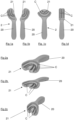
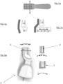
- Part 2 essentially has two parts, a part 20 constituting a handle for the practitioner to grip, and an active part 21, which includes the sensors C.
- the figures 1a and 1b represent impression trays 1 intended for taking an impression of a hemi-arch, and the figures 1c and 1d impression trays 1 for taking an impression of part of an arch.
- the part preferably comprises means, not shown arranged between the series of sensors C, for projecting passive, unstructured light, produced by simple LEDs or laser or halogen to simply illuminate the interior of the mouth but not serving as a measurement vector.
- an impression tray 1 intended for taking an impression of a complete arch, the active part 21 being in the shape of an arc of a circle.
- Such an impression tray 1 can be adapted for taking impressions of the upper arch and the lower arch.
- the part 2 can be, without limitation, made of a deformable material such as a thermoplastic material or a flexible resin, and preferably not returning to the original shape after adaptation in the patient's mouth.
- a deformable material such as a thermoplastic material or a flexible resin
- the sensors are provided capable, during the deformation of adjustment to the patient's mouth, to move individually or in groups, so as not to move too far from their known spatial positions. and calibrated.
- the sensors can be, without limitation, arranged in pairs on the impression tray, not shown, and for example articulated to one another in each pair, to surround one or more teeth D, optimally, while remaining in the same plane.
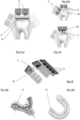
- the active part 21 of the part 2 has a complete arch and, not limited to, two parallel series in an arc of a circle of sensors C, and an element 22 is secured to the active part 21, this element 22 comprising a third series of sensors, thus increasing the precision, resolution and/or measuring area.
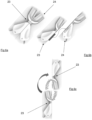
- an impression tray 2 made of two assembled parts 23 and 24, each corresponding, at the level of their active part, to a half-arch, which it is possible to use separately, or together for taking impressions. imprint of an arch, the joining being carried out, non-limitatively, mechanically or magnetically, through a means N. It will be noted that it is possible to provide more than two assemblable parts.
- This configuration makes it possible to simplify and reduce the number of impression trays since the impression tray 23 of the upper left hemi-arch corresponds to the impression tray of the lower right half arch, so that two impression trays 23 and 24 make it possible to make the four half arches but also, by bringing them together, to make the two complete upper and lower arches.
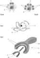
- the active part 21 can be in the form of a plate having a particular shape, for example curved, adapted, possibly adaptable, to the particularities of the occlusion, so as to allow the arches to be photographed up and down in occlusion.
- the active part 21 is concave in shape facing the teeth, on the figure 11c it has an offset, in order to measure disengagement, a fundamental value in occlusion movements and making it possible to define the dynamic modeling of the occlusal surface without having to resort to the complex systems of mechanical or electronic facial arches.
- a calibration system allowing at any time to check the correct positioning of the sensors and sensors of the different analysis methods during the life of the impression tray, especially for controlling the positioning of the optical parts C and OCT T, but also to rebalance the position of the sensors and inform the image processing system of the position of the sensors after deformation and adaptation in the patient's mouth by the clinician.
- This SC calibration system can have a flat or curved shape to be able to be inserted into the impression trays.
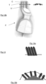
- Support on the teeth D can be achieved in several ways, through a spacer 3 such as a rod, a point, a ball or a blade 30, visible on the figure 14c , or a transparent wall 31, such as a window for example, visible on the figures 14a and 14b .
- a spacer 3 such as a rod, a point, a ball or a blade 30, visible on the figure 14c , or a transparent wall 31, such as a window for example, visible on the figures 14a and 14b .
- the transparent wall 31 can partially or completely cover the occlusal surface and/or the vestibular and/or lingual surfaces, as shown in the figure. Figure 15 .
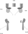
- the latter may carry engravings or targets G represented on the figures 16a and 16b , visible on the computer screen and allowing the impression tray to be correctly positioned in the desired area before reading but also to follow the progress of the impression taking during reading.
- a second transparent wall 32 is added sliding on the first 31 within the limits of the accepted movement, as shown in the figures.
- figures 17a and 17b on the latter is represented a motor M which makes it possible to generate the friction movement.
- the lighting system is preferably peripheral to the transparent wall(s), 31, 32, to avoid reflections on surfaces that could interfere with good reading.
- a lighting system 4 of the LED type for example behind the transparent wall(s) 31, the glass then being chosen as non-reflective as possible and the projection of the light will be made in such a way that its optical axis and its reflection if it exists, arrive as little as possible in the measured area.
- the 2nd will preferably be in the zone opposite therefore end then the 3rd flash in the start zone then the 4th in the end zone and so on.
- a system S for saliva suction and/or water and/or air projection can be added to keep the measured area as clear as possible, excluding saliva, blood or mist.
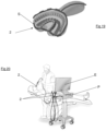
- These systems whose source of fluid, suction or energy are always present on the dental unit, will be adaptable to all or part (for example periphery) of the impression tray, as shown schematically on the Figure 19 .
- means may be provided for heating the impression tray and/or the transparent wall.
- This installation comprises a computer P for processing the captured images equipped with a display screen E. it also comprises one or more impression trays according to the invention, in this case several, is connected by wire, knowing that It is also possible to have a wireless connection via WIFI, Bluetooth or any other network.
- the shooting can be triggered by button, voice or using a pedal by practitioner D or by a button for patient P.
- the impression tray 2 can be in a single part or in two parts, that is to say that the active part 21 can be independent, in order to lighten the part close to the mouth.
- the active part 21 being connected to the rest of the impression tray or to the computer, not visible, through a wire F, preferably by a wireless communication system. thread.
Landscapes
- Health & Medical Sciences (AREA)
- Public Health (AREA)
- Epidemiology (AREA)
- Life Sciences & Earth Sciences (AREA)
- Animal Behavior & Ethology (AREA)
- General Health & Medical Sciences (AREA)
- Dentistry (AREA)
- Veterinary Medicine (AREA)
- Oral & Maxillofacial Surgery (AREA)
- Physics & Mathematics (AREA)
- Optics & Photonics (AREA)
- Dental Tools And Instruments Or Auxiliary Dental Instruments (AREA)
- Dental Prosthetics (AREA)
Applications Claiming Priority (3)
| Application Number | Priority Date | Filing Date | Title |
|---|---|---|---|
| FR1850689A FR3077196B1 (fr) | 2018-01-29 | 2018-01-29 | Porte empreinte electronique pour le captage d'information dentaire |
| EP19707857.9A EP3745995B1 (de) | 2018-01-29 | 2019-01-29 | Elektronische abdruckschale zur gewinnung von zahninformationen |
| PCT/FR2019/050184 WO2019145658A1 (fr) | 2018-01-29 | 2019-01-29 | Porte-empreinte electronique pour le captage d'information dentaire |
Related Parent Applications (2)
| Application Number | Title | Priority Date | Filing Date |
|---|---|---|---|
| EP19707857.9A Division EP3745995B1 (de) | 2018-01-29 | 2019-01-29 | Elektronische abdruckschale zur gewinnung von zahninformationen |
| EP19707857.9A Division-Into EP3745995B1 (de) | 2018-01-29 | 2019-01-29 | Elektronische abdruckschale zur gewinnung von zahninformationen |
Publications (2)
| Publication Number | Publication Date |
|---|---|
| EP4327775A2 true EP4327775A2 (de) | 2024-02-28 |
| EP4327775A3 EP4327775A3 (de) | 2024-05-22 |
Family
ID=63407262
Family Applications (2)
| Application Number | Title | Priority Date | Filing Date |
|---|---|---|---|
| EP24152012.1A Withdrawn EP4327775A3 (de) | 2018-01-29 | 2019-01-29 | Elektronischer abdrucklöffel zur erfassung von zahninformation |
| EP19707857.9A Active EP3745995B1 (de) | 2018-01-29 | 2019-01-29 | Elektronische abdruckschale zur gewinnung von zahninformationen |
Family Applications After (1)
| Application Number | Title | Priority Date | Filing Date |
|---|---|---|---|
| EP19707857.9A Active EP3745995B1 (de) | 2018-01-29 | 2019-01-29 | Elektronische abdruckschale zur gewinnung von zahninformationen |
Country Status (6)
| Country | Link |
|---|---|
| US (1) | US11357601B2 (de) |
| EP (2) | EP4327775A3 (de) |
| JP (1) | JP7451425B2 (de) |
| CN (1) | CN112351750B (de) |
| FR (1) | FR3077196B1 (de) |
| WO (1) | WO2019145658A1 (de) |
Families Citing this family (4)
| Publication number | Priority date | Publication date | Assignee | Title |
|---|---|---|---|---|
| GB201802402D0 (en) * | 2018-02-14 | 2018-03-28 | Littlejohn Alexander | Apparatus and method for prosthodontics |
| US11382727B1 (en) * | 2021-05-19 | 2022-07-12 | Thamer Marghalani | Three-dimensional oral imaging system and method |
| CN113509280B (zh) * | 2021-06-25 | 2023-04-18 | 杭州口腔医院集团有限公司 | 一种用于口腔修复体的无模数字化适配系统及其方法 |
| FR3153518B1 (fr) | 2023-06-27 | 2026-02-20 | Invisart | Dispositif porte empreinte optique |
Citations (6)
| Publication number | Priority date | Publication date | Assignee | Title |
|---|---|---|---|---|
| EP0040165A1 (de) | 1980-05-09 | 1981-11-18 | François Duret | Verfahren zum Herstellen einer Prothese |
| EP0091876A1 (de) | 1982-04-14 | 1983-10-19 | Duret, François | Vorrichtung zur Abdrucknahme durch optische Mittel, insbesondere zur automatischen Herstellung von Zahnprothesen |
| WO2011154656A1 (fr) | 2010-06-08 | 2011-12-15 | Duret Francois | Dispositif de mesures tridimensionnelles et temporelles par empreinte optique en couleur |
| US20150118638A1 (en) | 2012-04-05 | 2015-04-30 | Trispera Dental, Inc. | Intraoral Imaging Apparatus |
| US20170100219A1 (en) | 2009-01-15 | 2017-04-13 | Medentic S.A. | Impression tray, and method for capturing structures, arrangements or shapes, in particular in the mouth or human body |
| US20170128173A1 (en) | 2014-03-27 | 2017-05-11 | Dentsply Sirona Inc. | Scanning device |
Family Cites Families (29)
| Publication number | Priority date | Publication date | Assignee | Title |
|---|---|---|---|---|
| DE2936847A1 (de) * | 1979-09-12 | 1981-03-19 | Paul Dr. 6054 Rodgau Heitlinger | Verfahren zur herstellung von zahnersatz und vorrichtung zur durchfuehrung des verfahrens |
| US5316473A (en) * | 1988-06-17 | 1994-05-31 | Dentsply Research & Development Corp. | Light curing apparatus and method |
| US5487662A (en) * | 1994-03-22 | 1996-01-30 | Minnesota Mining And Manufacturing Company | Dental impression tray for photocurable impression material |
| US6217334B1 (en) * | 1997-01-28 | 2001-04-17 | Iris Development Corporation | Dental scanning method and apparatus |
| JP2000122641A (ja) | 1998-10-21 | 2000-04-28 | Casio Comput Co Ltd | 電子管楽器 |
| JP2001275964A (ja) * | 2000-03-29 | 2001-10-09 | Matsushita Electric Ind Co Ltd | ビデオスコープ |
| US6386867B1 (en) * | 2000-11-30 | 2002-05-14 | Duane Milford Durbin | Method and system for imaging and modeling dental structures |
| US6976841B1 (en) * | 2002-02-21 | 2005-12-20 | Nova Ranger, Inc. | Intra oral dental irradiation device for material curing and dental imaging |
| FR2844719B1 (fr) * | 2002-09-24 | 2004-11-19 | Francois Duret | Dispositif electro-chimique pour le blanchiment d'un corps |
| JP4822454B2 (ja) | 2005-11-22 | 2011-11-24 | 株式会社松風 | 歯科用光コヒーレンストモグラフィー装置 |
| US7690918B2 (en) * | 2006-02-27 | 2010-04-06 | Thuy-tien Tran HO | Dental impression trays |
| JP2008194107A (ja) | 2007-02-09 | 2008-08-28 | Shiyoufuu:Kk | 歯科用3次元上特性測定・表示装置 |
| WO2009042957A2 (en) * | 2007-09-26 | 2009-04-02 | Indentiv, Llc | Methods, devices, systems, assemblies, and kits for tissue retraction in an oral cavity |
| CN201101589Y (zh) * | 2007-10-31 | 2008-08-20 | 张国强 | 上下局部义齿同时制模的可调式联体印模托盘 |
| US9763760B2 (en) * | 2008-07-01 | 2017-09-19 | Ivoclar Vivadent Ag | Apparatus for light-curing a dental object |
| EP2736448B1 (de) * | 2011-07-29 | 2015-09-23 | 3Shape A/S | Angepasster zahnärztlicher abdrucklöffel |
| JP6042862B2 (ja) * | 2012-02-15 | 2016-12-14 | メディア株式会社 | 口腔内歯列撮影装置 |
| US9974630B2 (en) * | 2012-04-13 | 2018-05-22 | Orthoaccel Technologies, Inc. | Laser orthodontic devices |
| EP3610828B1 (de) * | 2012-06-15 | 2023-05-03 | VITA-ZAHNFABRIK H. Rauter GmbH & Co. KG | Verfahren zur herstellung einer teilweisen oder vollständigen zahnprothese |
| KR101499649B1 (ko) * | 2013-08-20 | 2015-03-06 | 조현재 | 구강촬영용 트레이, 구강촬영용 트레이를 포함하는 구강촬영장치 및 구강촬영 시스템 |
| GB201317478D0 (en) * | 2013-10-02 | 2013-11-13 | Provost Fellows Foundation Scholars And The Other Members Of Board Of The | A sensor for an oral appliance |
| US9131909B1 (en) * | 2014-04-01 | 2015-09-15 | Jonathan Ganz | Low emission full mouth xray apparatus |
| CH709747A1 (de) * | 2014-06-11 | 2015-12-15 | Quarz Partners Ag | Verfahren und Vorrichtung zum dreidimensionalen Ausmessen von Zahnreihen. |
| US10504386B2 (en) * | 2015-01-27 | 2019-12-10 | Align Technology, Inc. | Training method and system for oral-cavity-imaging-and-modeling equipment |
| US9844426B2 (en) * | 2015-03-12 | 2017-12-19 | Align Technology, Inc. | Digital dental tray |
| WO2017136471A1 (en) * | 2016-02-01 | 2017-08-10 | Martin Marco | Dental imager and method for recording photographic impressions |
| EP4670634A3 (de) * | 2016-06-17 | 2026-01-21 | Align Technology, Inc. | System zur bestimmung der patientenkonformität mit einem orthodontischen behandlungs- oder retentionsplan |
| EP3592281B1 (de) * | 2017-03-09 | 2021-08-04 | Deventiv Sp. z o.o. | Intraorale abtastvorrichtung, verfahren zum betrieb solch einer vorrichtung und abtastsystem |
| KR101994522B1 (ko) * | 2017-06-14 | 2019-07-01 | 한국광기술원 | 근적외선 기반 치아 진단 영상 획득 장치 및 방법 |
-
2018
- 2018-01-29 FR FR1850689A patent/FR3077196B1/fr not_active Expired - Fee Related
-
2019
- 2019-01-29 JP JP2020561949A patent/JP7451425B2/ja active Active
- 2019-01-29 EP EP24152012.1A patent/EP4327775A3/de not_active Withdrawn
- 2019-01-29 US US16/965,958 patent/US11357601B2/en active Active
- 2019-01-29 CN CN201980010802.1A patent/CN112351750B/zh active Active
- 2019-01-29 WO PCT/FR2019/050184 patent/WO2019145658A1/fr not_active Ceased
- 2019-01-29 EP EP19707857.9A patent/EP3745995B1/de active Active
Patent Citations (6)
| Publication number | Priority date | Publication date | Assignee | Title |
|---|---|---|---|---|
| EP0040165A1 (de) | 1980-05-09 | 1981-11-18 | François Duret | Verfahren zum Herstellen einer Prothese |
| EP0091876A1 (de) | 1982-04-14 | 1983-10-19 | Duret, François | Vorrichtung zur Abdrucknahme durch optische Mittel, insbesondere zur automatischen Herstellung von Zahnprothesen |
| US20170100219A1 (en) | 2009-01-15 | 2017-04-13 | Medentic S.A. | Impression tray, and method for capturing structures, arrangements or shapes, in particular in the mouth or human body |
| WO2011154656A1 (fr) | 2010-06-08 | 2011-12-15 | Duret Francois | Dispositif de mesures tridimensionnelles et temporelles par empreinte optique en couleur |
| US20150118638A1 (en) | 2012-04-05 | 2015-04-30 | Trispera Dental, Inc. | Intraoral Imaging Apparatus |
| US20170128173A1 (en) | 2014-03-27 | 2017-05-11 | Dentsply Sirona Inc. | Scanning device |
Also Published As
| Publication number | Publication date |
|---|---|
| JP7451425B2 (ja) | 2024-03-18 |
| WO2019145658A1 (fr) | 2019-08-01 |
| FR3077196B1 (fr) | 2023-05-26 |
| JP2021511938A (ja) | 2021-05-13 |
| CN112351750A (zh) | 2021-02-09 |
| US20210045851A1 (en) | 2021-02-18 |
| CN112351750B (zh) | 2022-06-03 |
| US11357601B2 (en) | 2022-06-14 |
| FR3077196A1 (fr) | 2019-08-02 |
| EP3745995B1 (de) | 2024-03-06 |
| EP3745995A1 (de) | 2020-12-09 |
| EP4327775A3 (de) | 2024-05-22 |
Similar Documents
| Publication | Publication Date | Title |
|---|---|---|
| EP2579766B1 (de) | Vorrichtung zur aufnahme dreidimensionaler und zeitlicher optischer abdrücke in farbe | |
| EP3745995B1 (de) | Elektronische abdruckschale zur gewinnung von zahninformationen | |
| EP0091876B1 (de) | Vorrichtung zur Abdrucknahme durch optische Mittel, insbesondere zur automatischen Herstellung von Zahnprothesen | |
| DK2668904T3 (en) | Spectral filter for an intraoral imaging system | |
| EP3148402B1 (de) | Vorrichtung zur betrachtung der innenseite des mundes eines patienten | |
| FR2977469A1 (fr) | Dispositif de mesure tridimensionnelle utilise dans le domaine dentaire | |
| CA2003263C (fr) | Dispositif de mesure et d'analyse de mouvements du corps humain ou de parties de celui-ci | |
| EP3415082A1 (de) | Vorrichtung zur aufnahme von zahnbildern | |
| EP3391811A1 (de) | Vorrichtung zur aufnahme von zahnbildern | |
| CN102802520A (zh) | 聚焦扫描设备 | |
| EP4161434B1 (de) | Verfahren zur verfolgung einer zahnbewegung | |
| WO2022248510A1 (fr) | Procédé de distribution de gouttières orthodontiques | |
| FR3123200A1 (fr) | Procede d’acquisition d’un modele d’une arcade dentaire | |
| FR2977473A1 (fr) | Dispositif de mesure tridimensionnelle utilise dans le domaine dentaire | |
| FR3153518A1 (fr) | Dispositif porte empreinte optique | |
| JP4515977B2 (ja) | 歯科用シェードガイドホルダ | |
| WO2025068405A1 (fr) | Dispositif de prise d'empreinte optique | |
| FR3139004A1 (fr) | Procédé de scannage d’une arcade dentaire d’un utilisateur | |
| FR3047165A1 (fr) | Dispositif de parure dentaire amovible |
Legal Events
| Date | Code | Title | Description |
|---|---|---|---|
| PUAI | Public reference made under article 153(3) epc to a published international application that has entered the european phase |
Free format text: ORIGINAL CODE: 0009012 |
|
| STAA | Information on the status of an ep patent application or granted ep patent |
Free format text: STATUS: THE APPLICATION HAS BEEN PUBLISHED |
|
| AC | Divisional application: reference to earlier application |
Ref document number: 3745995 Country of ref document: EP Kind code of ref document: P |
|
| AK | Designated contracting states |
Kind code of ref document: A2 Designated state(s): AL AT BE BG CH CY CZ DE DK EE ES FI FR GB GR HR HU IE IS IT LI LT LU LV MC MK MT NL NO PL PT RO RS SE SI SK SM TR |
|
| REG | Reference to a national code |
Ref country code: DE Ref legal event code: R079 Free format text: PREVIOUS MAIN CLASS: A61C0017060000 Ipc: A61C0009000000 |
|
| PUAL | Search report despatched |
Free format text: ORIGINAL CODE: 0009013 |
|
| AK | Designated contracting states |
Kind code of ref document: A3 Designated state(s): AL AT BE BG CH CY CZ DE DK EE ES FI FR GB GR HR HU IE IS IT LI LT LU LV MC MK MT NL NO PL PT RO RS SE SI SK SM TR |
|
| RIC1 | Information provided on ipc code assigned before grant |
Ipc: A61C 17/06 20060101ALI20240415BHEP Ipc: A61C 17/02 20060101ALI20240415BHEP Ipc: A61C 9/00 20060101AFI20240415BHEP |
|
| STAA | Information on the status of an ep patent application or granted ep patent |
Free format text: STATUS: THE APPLICATION IS DEEMED TO BE WITHDRAWN |
|
| 18D | Application deemed to be withdrawn |
Effective date: 20241123 |