EP4328080A1 - Verfahren und vorrichtung zur steuerung des abschaltens eines fahrzeugs sowie medium und vorrichtung - Google Patents
Verfahren und vorrichtung zur steuerung des abschaltens eines fahrzeugs sowie medium und vorrichtung Download PDFInfo
- Publication number
- EP4328080A1 EP4328080A1 EP22803656.2A EP22803656A EP4328080A1 EP 4328080 A1 EP4328080 A1 EP 4328080A1 EP 22803656 A EP22803656 A EP 22803656A EP 4328080 A1 EP4328080 A1 EP 4328080A1
- Authority
- EP
- European Patent Office
- Prior art keywords
- vehicle
- power
- hcu
- relay
- bms
- Prior art date
- Legal status (The legal status is an assumption and is not a legal conclusion. Google has not performed a legal analysis and makes no representation as to the accuracy of the status listed.)
- Withdrawn
Links
Images


Classifications
-
- B—PERFORMING OPERATIONS; TRANSPORTING
- B60—VEHICLES IN GENERAL
- B60L—PROPULSION OF ELECTRICALLY-PROPELLED VEHICLES; SUPPLYING ELECTRIC POWER FOR AUXILIARY EQUIPMENT OF ELECTRICALLY-PROPELLED VEHICLES; ELECTRODYNAMIC BRAKE SYSTEMS FOR VEHICLES IN GENERAL; MAGNETIC SUSPENSION OR LEVITATION FOR VEHICLES; MONITORING OPERATING VARIABLES OF ELECTRICALLY-PROPELLED VEHICLES; ELECTRIC SAFETY DEVICES FOR ELECTRICALLY-PROPELLED VEHICLES
- B60L58/00—Methods or circuit arrangements for monitoring or controlling batteries or fuel cells, specially adapted for electric vehicles
- B60L58/10—Methods or circuit arrangements for monitoring or controlling batteries or fuel cells, specially adapted for electric vehicles for monitoring or controlling batteries
- B60L58/12—Methods or circuit arrangements for monitoring or controlling batteries or fuel cells, specially adapted for electric vehicles for monitoring or controlling batteries responding to state of charge [SoC]
-
- B—PERFORMING OPERATIONS; TRANSPORTING
- B60—VEHICLES IN GENERAL
- B60L—PROPULSION OF ELECTRICALLY-PROPELLED VEHICLES; SUPPLYING ELECTRIC POWER FOR AUXILIARY EQUIPMENT OF ELECTRICALLY-PROPELLED VEHICLES; ELECTRODYNAMIC BRAKE SYSTEMS FOR VEHICLES IN GENERAL; MAGNETIC SUSPENSION OR LEVITATION FOR VEHICLES; MONITORING OPERATING VARIABLES OF ELECTRICALLY-PROPELLED VEHICLES; ELECTRIC SAFETY DEVICES FOR ELECTRICALLY-PROPELLED VEHICLES
- B60L3/00—Electric devices on electrically-propelled vehicles for safety purposes; Monitoring operating variables, e.g. speed, deceleration or energy consumption
- B60L3/0023—Detecting, eliminating, remedying or compensating for drive train abnormalities, e.g. failures within the drive train
-
- B—PERFORMING OPERATIONS; TRANSPORTING
- B60—VEHICLES IN GENERAL
- B60L—PROPULSION OF ELECTRICALLY-PROPELLED VEHICLES; SUPPLYING ELECTRIC POWER FOR AUXILIARY EQUIPMENT OF ELECTRICALLY-PROPELLED VEHICLES; ELECTRODYNAMIC BRAKE SYSTEMS FOR VEHICLES IN GENERAL; MAGNETIC SUSPENSION OR LEVITATION FOR VEHICLES; MONITORING OPERATING VARIABLES OF ELECTRICALLY-PROPELLED VEHICLES; ELECTRIC SAFETY DEVICES FOR ELECTRICALLY-PROPELLED VEHICLES
- B60L2240/00—Control parameters of input or output; Target parameters
- B60L2240/80—Time limits
-
- B—PERFORMING OPERATIONS; TRANSPORTING
- B60—VEHICLES IN GENERAL
- B60L—PROPULSION OF ELECTRICALLY-PROPELLED VEHICLES; SUPPLYING ELECTRIC POWER FOR AUXILIARY EQUIPMENT OF ELECTRICALLY-PROPELLED VEHICLES; ELECTRODYNAMIC BRAKE SYSTEMS FOR VEHICLES IN GENERAL; MAGNETIC SUSPENSION OR LEVITATION FOR VEHICLES; MONITORING OPERATING VARIABLES OF ELECTRICALLY-PROPELLED VEHICLES; ELECTRIC SAFETY DEVICES FOR ELECTRICALLY-PROPELLED VEHICLES
- B60L2270/00—Problem solutions or means not otherwise provided for
- B60L2270/10—Emission reduction
- B60L2270/14—Emission reduction of noise
- B60L2270/142—Emission reduction of noise acoustic
-
- Y—GENERAL TAGGING OF NEW TECHNOLOGICAL DEVELOPMENTS; GENERAL TAGGING OF CROSS-SECTIONAL TECHNOLOGIES SPANNING OVER SEVERAL SECTIONS OF THE IPC; TECHNICAL SUBJECTS COVERED BY FORMER USPC CROSS-REFERENCE ART COLLECTIONS [XRACs] AND DIGESTS
- Y02—TECHNOLOGIES OR APPLICATIONS FOR MITIGATION OR ADAPTATION AGAINST CLIMATE CHANGE
- Y02T—CLIMATE CHANGE MITIGATION TECHNOLOGIES RELATED TO TRANSPORTATION
- Y02T10/00—Road transport of goods or passengers
- Y02T10/60—Other road transportation technologies with climate change mitigation effect
- Y02T10/70—Energy storage systems for electromobility, e.g. batteries
-
- Y—GENERAL TAGGING OF NEW TECHNOLOGICAL DEVELOPMENTS; GENERAL TAGGING OF CROSS-SECTIONAL TECHNOLOGIES SPANNING OVER SEVERAL SECTIONS OF THE IPC; TECHNICAL SUBJECTS COVERED BY FORMER USPC CROSS-REFERENCE ART COLLECTIONS [XRACs] AND DIGESTS
- Y02—TECHNOLOGIES OR APPLICATIONS FOR MITIGATION OR ADAPTATION AGAINST CLIMATE CHANGE
- Y02T—CLIMATE CHANGE MITIGATION TECHNOLOGIES RELATED TO TRANSPORTATION
- Y02T90/00—Enabling technologies or technologies with a potential or indirect contribution to GHG emissions mitigation
- Y02T90/10—Technologies relating to charging of electric vehicles
- Y02T90/16—Information or communication technologies improving the operation of electric vehicles
Definitions
- the present disclosure relates to the field of electric vehicle automatic control technology, and more particularly to a method and a device for controlling vehicle power-off, a medium, and an apparatus.
- New energy vehicles have added power-on and power-off functions, which control high-voltage (60 V ⁇ 1500 V) components (such as a DC/DC) and driving components to enter/exit working mode through complex control strategies.
- high-voltage 60 V ⁇ 1500 V
- DC/DC DC/DC
- driving components such as a DC/DC
- the high-voltage components of the new energy vehicles are controlled to exit the working mode, the most important thing is to enable the high-voltage power battery to turn-on the relay and complete the high-voltage power-off.
- the contacts of the relay of the high-voltage power battery are disconnected, there will be a sound, causing the driver to hear the sound of the relay of the power battery being disconnected when the vehicle is powered off, which can cause confusion or dissatisfaction of the driver. Therefore, dealing with the sound of the relay of the high-voltage battery generated when being turned on has become a problem that engineers have to consider.
- An object of the present disclosure is to provide an intelligent and an energy-saving method and device for controlling vehicle power-off, a medium, and a device.
- the present disclosure provides a method and for controlling vehicle power-off, and the method includes steps of:
- the method further includes: sending directly, by the HCU, the relay disconnection request to the BMS if it is determined that the state of the vehicle meets the preset power-off condition and the SOC of the power battery is less than or equal to the predetermined charging threshold.
- the method further includes: sending, by the HCU, the relay disconnection request to the BMS if the timekeeping reaches the predetermined period.
- the method further includes:
- the preset power-off condition includes that: a vehicle speed is less than a predetermined vehicle speed threshold, a engine rotating speed is less than a predetermined rotating speed threshold, a belt-driven starter generator exits a working state, a DCDC exits the working state, an SOC of a low-voltage battery is greater than a predetermined power threshold, and a current in a high-voltage circuit is less than a predetermined current threshold.
- the present disclosure provides a device for controlling vehicle power-off, and the device includes:
- the HCU is further configured for sending directly the relay disconnection request to the BMS if it is determined that the state of the vehicle meets the preset power-off condition and the SOC of the power battery is less than or equal to the predetermined charging threshold.
- the HCU is further configured for sending the relay disconnection request to the BMS if the timekeeping reaches the predetermined period.
- the present disclosure further provides a computer-readable storage medium storing a computer program thereon, and when the computer program is executed by a processor, the steps of the method in the present disclosure can be implemented.
- the present disclosure further provides an electronic apparatus, comprising: a memory storing a computer program thereon; a processor configured for executing the computer program in the memory to implement the steps of the method in the present disclosure.
- the HCU starts the timekeeping; when it is detected that a driver is absent in the vehicle and the timekeeping reaches a predetermined period, the HCU sends the relay disconnection request to the BMS, so that the BMS controls the relay of the power battery to be disconnected.
- the relay of the power battery is controlled to be disconnected, which can avoid the noise generated by the contacts of the relay disconnecting from affecting the driver; on the other hand, the energy state of the power battery is also considered to ensure that the delayed disconnection of the contacts of the relay does not significantly affect the energy reserve of the power battery, thus minimizing the impact of noise on the driver while ensuring the existing endurance of the vehicle.
- New energy vehicles have added power-on and power-off functions, which control high-voltage components and driving components to enter/exit working mode through complex control strategies.
- the high-voltage components of the new energy vehicles are controlled to exit the working mode, the most important thing is to enable the high-voltage power battery to turn-on the relay and complete the high-voltage power-off. Due to the hardware characteristics of the power battery, an obvious sound will be generated when the contacts of the relay of the power battery are turned on, which causes the driver to hear obvious abnormal noises during the process of parking and powering off the vehicle, which is a type of noise for the driver. Under the condition of ensuring the existing endurance of the vehicle, the noise effect on the driver caused by the disconnection of the contacts of the relay is avoided as far as possible.
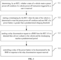
- FIG. 1 is a flowchart of a method for controlling vehicle power-off provided in an exemplary embodiment. As shown in FIG. 1 , the method can include the following steps.
- step S11 determining, by an HCU, whether a state of a vehicle meets a preset power-off condition if a vehicle power-off instruction triggered by a user is received.
- step S12 starting a timekeeping by the HCU when the state of the vehicle is determined to meet the preset power-off condition and an SOC of a power battery is greater than a predetermined charging threshold.
- step S13 sending, by the HCU, a relay disconnection request to a BMS if it is detected that a driver is absent in the vehicle and the timekeeping reaches a predetermined period.
- step S14 controlling, by the BMS, a relay of the power battery to be disconnected in response to the relay disconnection request received.
- the user can trigger a specific button to send the vehicle power-off instructions to the HCU.
- the HCU controls the vehicle to complete the power-off after the vehicle power-off instruction is received.
- PEPS Passive Entry Passive Start
- the HCU when the vehicle power-off instruction is received, the HCU can first determine whether the state of the vehicle meets the preset power-off condition. If the above preset power-off condition is met, then it can be considered that the relay of the power battery can be cut off to safely power off.
- the preset power-off condition can include: a vehicle speed is less than a predetermined vehicle speed threshold, a engine rotating speed is less than a predetermined rotating speed threshold (for example, if the engine rotating speed is less than 2km/h, the vehicle is considered to be stationary), a belt-driven starter generator exits a working state, a DCDC exits the working state, an SOC of a low-voltage battery is greater than a predetermined power threshold, and a current in a high-voltage circuit is less than a predetermined current threshold.
- a vehicle speed is less than a predetermined vehicle speed threshold
- a engine rotating speed is less than a predetermined rotating speed threshold (for example, if the engine rotating speed is less than 2km/h, the vehicle is considered to be stationary)
- a belt-driven starter generator exits a working state
- a DCDC exits the working state
- an SOC of a low-voltage battery is greater than a predetermined power threshold
- a current in a high-voltage circuit is
- the SOC of the power battery is greater than the predetermined charge threshold, it can be considered that the power battery has more power at present, which can allow the delayed disconnection of the relay of the power battery to avoid noise effects on the driver.
- Whether the driver leaves the seat and is not in the vehicle can be determined by the signal feedback by the gravity sensing seat configured in the vehicle. For example, if the signal feedback by the gravity sensing seat indicates that the weight on the seat is greater than the predetermined weight threshold, the driver can be considered to be still in the vehicle; conversely, if the signal feedback by the gravity sensing seat indicates that the weight on the seat is less than or equal to the predetermined weight threshold, the driver can be considered not in the vehicle.
- the HCU can further comprehensively determine whether the driver leaves the seat based on the acceleration pedal, brake pedal, seat belt state, and vehicle door state. For example, when the acceleration or brake pedal is depressed, the seat belt is not unfastened, and the door is not opened after the speed decreases to zero, any of these criteria can determine that the driver is still in the vehicle.
- the HCU After the user triggers the vehicle power-off instruction, and if it is detected that the driver is absent in the vehicle and the timekeeping reaches the predetermined period, then the HCU detects that the driver is absent in the vehicle and sends a relay disconnection request to the BMS to disconnect the relay that controls the power battery.
- the predetermined period can be based on trial or experience.
- the HCU starts the timekeeping; when it is detected that a driver is absent in the vehicle and the timekeeping reaches a predetermined period, the HCU sends the relay disconnection request to the BMS, so that the BMS controls the relay of the power battery to be disconnected.
- the relay of the power battery is controlled to be disconnected, which can avoid the noise generated by the contacts of the relay disconnecting from affecting the driver; on the other hand, the energy state of the power battery is also considered to ensure that the delayed disconnection of the contacts of the relay does not significantly affect the energy reserve of the power battery, thus minimizing the impact of noise on the driver while ensuring the existing endurance of the vehicle.
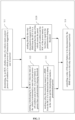
- FIG. 2 is a flowchart of a method for controlling vehicle power-off provided by another exemplary embodiment. As shown in FIG. 2 , the method can further include step S120 on basis of FIG. 1 .
- step S120 sending directly, by the HCU, the relay disconnection request to the BMS if it is determined that the state of the vehicle meets the preset power-off condition and the SOC of the power battery is less than or equal to the predetermined charging threshold.
- the SOC of the power battery is less than or equal to the predetermined charge threshold, it can be considered that the current power of the power battery is low. In order to ensure the subsequent power consumption, it is not considered to delay disconnecting the relay of the power battery, and the HCU does not timing and directly power off the vehicle when the relay is disconnected.
- priority is given to ensuring the endurance power consumption of the vehicle to avoid affecting the normal running of the vehicle due to the delayed disconnection of the relay.
- FIG. 3 is a flowchart of a method for controlling vehicle power-off provided by another exemplary embodiment;. As shown in FIG. 3 , the method can further include step S130 on basis of FIG. 1 .
- step S130 sending, by the HCU, the relay disconnection request to the BMS if the timekeeping reaches the predetermined period.
- the noise effect on the driver is avoided by making the delay disconnection of the contacts of the relay, the delay disconnection is limited to a predetermined period. If the predetermined period is exceeded, the noise effect is no longer considered, and the relay is directly controlled to be disconnected. This takes into account the power consumption of the vehicle when it is constantly powered, and the predetermined period is used to make a compromise between the power consumption and the noise influence. In the embodiment, both power consumption and noise influence are taken into account, and the noise influence on the driver is avoided as far as possible while the existing endurance of the vehicle is guaranteed.
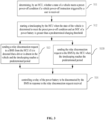
- FIG. 4 is a flowchart of a method for controlling vehicle power-off provided by another exemplary embodiment. As shown in FIG. 4 , on the basis of FIG. 1 , the method can further include the following steps after the step S 14 where the BMS controls the relay of power battery to be disconnected.
- step S15 detecting, by the BMS, whether the relay of the power battery is adhered.
- the expression "the relay of the power battery is adhered" or the like herein means the contacts of the replay connect together and cannot disconnect.
- step S 16 sending, by the BMS, a detected result to the HCU.
- step S17 controlling, by the HCU, the vehicle to enter a dormant state if the detected result indicates an absence of adhesion.
- the vehicle can be controlled into the dormant state after confirming that the relay is not adhered.
- Methods in related technologies can be applied to determine whether the relay is adhered.
- the safety of the vehicle is enhanced by controlling the vehicle to enter the dormant state while ensuring that the relay is not adhered.
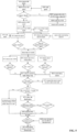
- FIG. is a flowchart of a method for controlling vehicle power-off provided by another exemplary embodiment. As shown in FIG. 5 , the method for controlling vehicle power-off can include the following steps.
- the instrument panel displays "the power battery is low, please charge it in time", and the HCU sends the relay disconnection request to the BMS;
- the HCU starts the timekeeping
- the HCU If it detects that the driver is absent in the vehicle and the timekeeping reaches a predetermined period (calibrated according to the comprehensive energy consumption of the delayed disconnection relay, e.g., 30s), the HCU sends the relay disconnection request to the BMS;
- the HCU sends the relay disconnection request to the BMS.
- the BMS controls to disconnect the relay and performs adhesion detection, the BMS reports the battery state and adhesion detection result to the HCU. If there is no adhesion, the HCU stops sending messages and enters the dormant state, and the vehicle is powered off.
- FIG. 6 is a block diagram of a device for controlling vehicle power-off provided in an exemplary embodiment.
- the vehicle 600 for controlling vehicle power-off can include the HCU 601 and the BMS 602.
- the HCU 601 is configured for determining whether a state of a vehicle meets a preset power-off condition if a vehicle power-off instruction triggered by a user is received; the HCU starts a timekeeping when the state of the vehicle is determined to meet the preset power-off condition and an SOC of a power battery is greater than a predetermined charging threshold; the HCU sends a relay disconnection request to the BMS 602 if it is detected that a driver is absent in the vehicle and the timekeeping reaches a predetermined period.
- the BMS 602 is configured for controlling the power battery to be disconnected in response to the relay disconnection request received.
- the HCU 601 is further configured for sending directly the relay disconnection request to the BMS 602 if it is determined that the state of the vehicle meets the preset power-off condition and the SOC of the power battery is less than or equal to the predetermined charging threshold.
- the HCU 601 is further configured for sending the relay disconnection request to the BMS 602 if the timekeeping reaches the predetermined period.
- the BMS 602 is further configured for detecting whether the relay of the power battery is adhered and sending the detected result to the HCU 601; the HCU 601 is further configured for controlling the vehicle to enter a dormant state if the detected result indicates an absence of adhesion.
- the preset power-off conditions include: a vehicle speed is less than a predetermined vehicle speed threshold, an engine rotating speed is less than a predetermined rotating speed threshold, a belt-driven starter generator exits a working state, a DCDC exits the working state, an SOC of a low-voltage battery is greater than a predetermined power threshold, and a current in a high-voltage circuit is less than a predetermined current threshold.
- the relay of the power battery is controlled to be disconnected, which can avoid the noise caused by the disconnection of contacts of the relay affecting the driver; on the other hand, the energy state of the power battery is also considered, so that the delayed disconnection of the contacts of the relay will not affect the energy reserve of the power battery too much, so as to avoid the noise influence on the driver as much as possible under the condition of guaranteeing the existing endurance of the vehicle.
- FIG. 7 is a block diagram of an electronic apparatus 700 provided in an exemplary embodiment.
- the electronic apparatus 700 can include: a processor 701 and a memory 702.
- the electronic apparatus 700 can further include a multimedia component 703, an input/output (I/O) interface 704, and one or more of communication components 705.
- I/O input/output
- the processor 701 is used to control the overall operation of the electronic apparatus 700 to complete all or part of the steps in the method for controlling vehicle power-off described above.
- the memory 702 is used to store various types of data to support operations on the electronic apparatus 700, the data can include, for example, instructions for any application or method used to operate on the electronic apparatus 700, as well as application-related data, such as contact data, incoming and outgoing messages, pictures, audio, video, and so on.
- the Memory 702 can be implemented by any type of volatile or non-volatile memory device or a combination of them, such as Static Random Access Memory (SRAM), Electrically Erasable Programmable Read-Only Memory (EEPROM), Erasable Programmable Read-Only Memory (EPROM), Programmable Read-Only Memory (PROM), Read Only Memory (ROM), magnetic memory, flash memory, disk or optical disc.
- Multimedia components 703 can include a screen and audio components.
- the screen for example, can be a touch screen, the audio components are used to output and/or input the audio signal.
- the audio components can include a microphone used to receive external audio signals.
- the received audio signals can be further stored in the memory 702 or sent via the communication components 705.
- the audio components further include at least one speaker for output of the audio signal.
- the I/O interface 704 provides an interface between the processor 701 and other interface modules, which can be keyboards, mice, buttons, etc. These buttons can be virtual buttons or physical buttons.
- the communication components 705 are used for wired or wireless communication between the electronic apparatus 700 and other devices. Wireless communications, such as Wi-Fi, Bluetooth, Near Field Communication (NFC), 2G, 3G, 4G, NB-IOT, eMTC, or other 5G, etc., or one or a combination of them, which is not limited herein. Therefore, the corresponding communication components 705 can include: Wi-Fi module, Bluetooth module, NFC module and so on.
- the electronic apparatus 700 can be used by one or more Application Specific Integrated circuits (ASIC), Digital Signal processor (DSP), Digital Signal Processing Device (DSPD), Programmable Logic Device (PLD), Field Programmable Gate Array (FPGA), controller, microcontroller, microprocessor or other electronic component implementation to perform the method for controlling vehicle power-off described above.
- ASIC Application Specific Integrated circuits
- DSP Digital Signal processor
- DSPD Digital Signal Processing Device
- PLD Programmable Logic Device
- FPGA Field Programmable Gate Array
- controller microcontroller, microprocessor or other electronic component implementation to perform the method for controlling vehicle power-off described above.
- a computer-readable storage medium including program instructions is also provided to implement the method for controlling vehicle power-off described above when the program instructions are executed by the processor.
- the computer readable storage medium can be the memory 702 including program instructions which can be executed by the processor 701 of the electronic apparatus 700 to complete the method for controlling vehicle power-off described above.
- a computer program product includes a computer program capable of being executed by a programmable device having a code portion for executing the method for controlling vehicle power-off described above when executed by the programmable device.
- first and second are only used in describe purposes, and should not be considered as indicating or implying any relative importance, or impliedly indicating the number of indicated technical features.
- technical feature(s) restricted by “the first” or “the second” can explicitly or impliedly include one or more such technical feature(s).
- a plurality of means two or more, unless there is additional explicit and specific limitation.
- Logic and/or steps expressed in a flowchart or otherwise described herein, for example, can be thought of as a fixed sequence list of executable instructions for performing a logical function, which can be concretely implemented in any computer-readable medium,
- an instruction executing system, device or apparatus such as a computer-based system, a system including a processor, or other system that can take instructions from and execute instructions from an instruction executing system, device or apparatus.
- "computer readable medium” can mean any device that can contain, store, communicate, transmit or transmit programs for use by or in conjunction with an instruction executing system, device or apparatus.
- computer readable media include the following: an electrical connection unit (electronic apparatus) having one or more wiring, a portable computer cartridge (magnetic device), a random access memory (RAM), a read-only memory (ROM), an erasable and editable read-only memory (EPROM or flash memory), an optical fiber device, and a portable optical disc read-only memory (CDROM).
- the computer-readable medium can even be paper or other suitable medium on which the program can be printed, since the program can be obtained electronically, for example, by optical scanning of the paper or other medium, followed by editing, interpreting or, if necessary, processing in other suitable ways, and then stored in a computer memory.
- parts of the present disclosure can be implemented with hardware, software, firmware, or a combination thereof.
- multiple steps or methods can be implemented with software or firmware stored in memory and executed by a suitable instruction execution system.
- a suitable instruction execution system For example, if implemented in hardware as in another embodiment, it can be implemented using any of the following technologies known in the art, or a combination thereof: discrete logic circuits with logic gates for implementing logic functions on data signals, application-specific integrated circuits with suitable combinational logic gates, programmable gate arrays (PGA), field programmable gate arrays (FPGA), etc.
- the functional units in various embodiments of the present disclosure can be integrated in a single processing module, the units can exist physically separately, or two or more units can be integrated in a single module.
- the above integrated modules can be realized either in the form of hardware or software function modules.
- the integrated module if implemented in the form of a software function module and sold or used as a stand-alone product, can also be stored in a computer-readable storage medium.
- the above mentioned storage media can be read-only memory, disk or optical disc.
Landscapes
- Engineering & Computer Science (AREA)
- Life Sciences & Earth Sciences (AREA)
- Sustainable Development (AREA)
- Sustainable Energy (AREA)
- Power Engineering (AREA)
- Transportation (AREA)
- Mechanical Engineering (AREA)
- Charge And Discharge Circuits For Batteries Or The Like (AREA)
- Electric Propulsion And Braking For Vehicles (AREA)
Applications Claiming Priority (2)
| Application Number | Priority Date | Filing Date | Title |
|---|---|---|---|
| CN202110553911.7A CN114347850B (zh) | 2021-05-20 | 2021-05-20 | 车辆下电控制方法、装置、介质及设备 |
| PCT/CN2022/084180 WO2022242331A1 (zh) | 2021-05-20 | 2022-03-30 | 车辆下电控制方法、装置、介质及设备 |
Publications (2)
| Publication Number | Publication Date |
|---|---|
| EP4328080A1 true EP4328080A1 (de) | 2024-02-28 |
| EP4328080A4 EP4328080A4 (de) | 2024-10-30 |
Family
ID=81096373
Family Applications (1)
| Application Number | Title | Priority Date | Filing Date |
|---|---|---|---|
| EP22803656.2A Withdrawn EP4328080A4 (de) | 2021-05-20 | 2022-03-30 | Verfahren und vorrichtung zur steuerung des abschaltens eines fahrzeugs sowie medium und vorrichtung |
Country Status (3)
| Country | Link |
|---|---|
| EP (1) | EP4328080A4 (de) |
| CN (1) | CN114347850B (de) |
| WO (1) | WO2022242331A1 (de) |
Families Citing this family (10)
| Publication number | Priority date | Publication date | Assignee | Title |
|---|---|---|---|---|
| CN114537146B (zh) * | 2022-04-25 | 2022-08-23 | 潍柴动力股份有限公司 | 一种车辆控制方法、装置、电子设备和存储介质 |
| CN115576297B (zh) * | 2022-09-23 | 2024-12-31 | 北汽福田汽车股份有限公司 | 车辆上装控制方法、装置、介质及车辆 |
| CN116101200A (zh) * | 2023-02-10 | 2023-05-12 | 长城汽车股份有限公司 | 车辆报警方法、电子设备及车辆 |
| CN116714540B (zh) * | 2023-06-15 | 2026-01-13 | 中国第一汽车股份有限公司 | 一种车辆噪音规避方法、设备和介质 |
| CN116638972B (zh) * | 2023-06-15 | 2026-03-13 | 中国第一汽车股份有限公司 | 车辆放电的控制方法、装置及车辆 |
| CN118163629B (zh) * | 2024-04-15 | 2025-07-15 | 大陆软件系统开发中心(重庆)有限公司 | 用于车辆的节电控制方法及装置 |
| CN118790193B (zh) * | 2024-09-13 | 2025-01-14 | 江西江铃集团新能源汽车有限公司 | 一种纯电动汽车电控方法、纯电动汽车及存储介质 |
| CN119160109A (zh) * | 2024-10-18 | 2024-12-20 | 上汽通用五菱汽车股份有限公司 | 一种车辆的控制方法、模块及车辆 |
| CN119611153B (zh) * | 2024-12-11 | 2025-10-24 | 潍柴动力股份有限公司 | 用于电池过放时的驻车发电控制方法、系统、介质及设备 |
| CN120422662B (zh) * | 2025-06-26 | 2025-09-16 | 浙江吉利控股集团有限公司 | 车辆高压断电控制策略、控制系统及车辆 |
Family Cites Families (18)
| Publication number | Priority date | Publication date | Assignee | Title |
|---|---|---|---|---|
| JP2005278301A (ja) * | 2004-03-24 | 2005-10-06 | Toyota Motor Corp | ノイズのマスキング方法 |
| KR100829307B1 (ko) * | 2007-06-04 | 2008-05-13 | 현대자동차주식회사 | 하이브리드 전기 차량의 고전압 릴레이 고장진단 제어방법 |
| KR101086974B1 (ko) * | 2009-03-03 | 2011-11-29 | 주식회사 엘지화학 | 전기구동차량의 릴레이 제어 장치 및 방법 |
| JP2013010425A (ja) * | 2011-06-29 | 2013-01-17 | Showa Corp | 電動パワーステアリング装置 |
| JP2016010264A (ja) * | 2014-06-25 | 2016-01-18 | トヨタ自動車株式会社 | 蓄電システム |
| JP6623794B2 (ja) * | 2016-01-28 | 2019-12-25 | トヨタ自動車株式会社 | リレー固着検出システム |
| JP6614088B2 (ja) * | 2016-10-06 | 2019-12-04 | 株式会社デンソー | 電源システム制御装置 |
| CN108608865B (zh) * | 2016-12-09 | 2021-10-01 | 上海大郡动力控制技术有限公司 | 电动汽车整车控制器控制高压上下电的方法 |
| CN207190815U (zh) * | 2017-07-25 | 2018-04-06 | 郑州宇通客车股份有限公司 | 一种车辆及电动车蓄电池供电系统 |
| JP2019038476A (ja) * | 2017-08-28 | 2019-03-14 | カルソニックカンセイ株式会社 | リレーユニットおよび電池装置 |
| JP7214979B2 (ja) * | 2018-05-23 | 2023-01-31 | 株式会社Gsユアサ | 管理装置、及び、故障判断方法 |
| CN109484182A (zh) * | 2018-11-12 | 2019-03-19 | 安徽鑫盛汽车制造有限公司 | 一种电动汽车高压下电控制方法 |
| CN109795374A (zh) * | 2019-01-25 | 2019-05-24 | 汉腾汽车有限公司 | 一种混合动力汽车中氢燃料电池的控制方法及系统 |
| CN109849733B (zh) * | 2019-02-19 | 2021-02-19 | 广州小鹏汽车科技有限公司 | 用于电动车辆高压继电器粘连检测及处理的装置和方法 |
| CN110254236A (zh) * | 2019-06-18 | 2019-09-20 | 广西汽车集团有限公司 | 一种高压上电控制方法、装置和电动汽车 |
| CN110466355B (zh) * | 2019-08-29 | 2021-10-12 | 广州小鹏汽车科技有限公司 | 电动汽车智能高压延时下电控制方法及电动汽车 |
| CN112477605B (zh) * | 2020-12-04 | 2022-04-08 | 浙江吉利控股集团有限公司 | 一种车辆上下电的控制方法和控制系统 |
| CN113135112A (zh) * | 2021-04-20 | 2021-07-20 | 宝能汽车科技有限公司 | 下电控制方法、系统、电子设备及存储介质 |
-
2021
- 2021-05-20 CN CN202110553911.7A patent/CN114347850B/zh active Active
-
2022
- 2022-03-30 EP EP22803656.2A patent/EP4328080A4/de not_active Withdrawn
- 2022-03-30 WO PCT/CN2022/084180 patent/WO2022242331A1/zh not_active Ceased
Also Published As
| Publication number | Publication date |
|---|---|
| WO2022242331A1 (zh) | 2022-11-24 |
| EP4328080A4 (de) | 2024-10-30 |
| CN114347850A (zh) | 2022-04-15 |
| CN114347850B (zh) | 2025-01-24 |
Similar Documents
| Publication | Publication Date | Title |
|---|---|---|
| EP4328080A1 (de) | Verfahren und vorrichtung zur steuerung des abschaltens eines fahrzeugs sowie medium und vorrichtung | |
| JP6574456B2 (ja) | 電動車両の制御装置 | |
| CN112311071B (zh) | 混动车辆的电池包的保护方法和装置 | |
| JP5216106B2 (ja) | 自動車用電気システムおよび始動モータの制御方法およびこのような電気システムにおけるバッテリアイソレータ | |
| US20150336523A1 (en) | Vehicle power supply apparatus and vehicle power regeneration system | |
| EP3107181A2 (de) | Überwachungsvorrichtung für sekundärbatterie, batteriepack und schutzsystem für sekundärbatterie | |
| KR101491366B1 (ko) | 차량용 배터리 관리 장치 및 방법 | |
| CN113135112A (zh) | 下电控制方法、系统、电子设备及存储介质 | |
| CN112078423B (zh) | 一种车辆高压上电的控制方法、整车控制器、系统及车辆 | |
| CN111251942A (zh) | 一种电动汽车电池补电方法、系统及电动汽车 | |
| CN115384433A (zh) | 一种整车双低压电池智能控制方法及系统 | |
| WO2024255540A1 (zh) | 车辆碰撞安全保护系统、方法、车辆和介质 | |
| CN116853224B (zh) | 混合动力汽车模式切换控制方法、电子设备和存储介质 | |
| JP2005206085A (ja) | 電力分配システム、電力分配器、及びブレーキ装置 | |
| CN103287432A (zh) | 在发动机自动停止事件期间对车辆的电负载的控制 | |
| CN114771436B (zh) | 一种汽车双蓄电池控制方法及系统 | |
| CN114670674B (zh) | 汽车电机控制器工作模式管理方法、装置和汽车 | |
| US20240383420A1 (en) | Extended-use mode for an ancillary vehicle function | |
| CN118269668A (zh) | 车辆升级的控制方法、装置、车辆和存储介质 | |
| KR102598634B1 (ko) | 차량 전원 제어 장치 및 방법 | |
| CN115848218A (zh) | 一种车辆上下电控制方法、装置、存储介质及车辆 | |
| CN112659901B (zh) | 一种汽车上下电控制方法、装置、设备及存储介质 | |
| CN114454719B (zh) | 车辆控制方法和装置、介质、设备、车辆 | |
| JP2000344092A (ja) | エアコンプレッサ起動装置 | |
| CN118529030B (zh) | 泊车路径的地图构建方法、系统及车辆 |
Legal Events
| Date | Code | Title | Description |
|---|---|---|---|
| STAA | Information on the status of an ep patent application or granted ep patent |
Free format text: STATUS: THE INTERNATIONAL PUBLICATION HAS BEEN MADE |
|
| PUAI | Public reference made under article 153(3) epc to a published international application that has entered the european phase |
Free format text: ORIGINAL CODE: 0009012 |
|
| STAA | Information on the status of an ep patent application or granted ep patent |
Free format text: STATUS: REQUEST FOR EXAMINATION WAS MADE |
|
| 17P | Request for examination filed |
Effective date: 20231120 |
|
| AK | Designated contracting states |
Kind code of ref document: A1 Designated state(s): AL AT BE BG CH CY CZ DE DK EE ES FI FR GB GR HR HU IE IS IT LI LT LU LV MC MK MT NL NO PL PT RO RS SE SI SK SM TR |
|
| DAV | Request for validation of the european patent (deleted) | ||
| DAX | Request for extension of the european patent (deleted) | ||
| A4 | Supplementary search report drawn up and despatched |
Effective date: 20240925 |
|
| RIC1 | Information provided on ipc code assigned before grant |
Ipc: B60L 3/00 20190101ALI20240920BHEP Ipc: B60L 58/12 20190101ALI20240920BHEP Ipc: B60L 58/10 20190101AFI20240920BHEP |
|
| STAA | Information on the status of an ep patent application or granted ep patent |
Free format text: STATUS: EXAMINATION IS IN PROGRESS |
|
| 17Q | First examination report despatched |
Effective date: 20250701 |
|
| STAA | Information on the status of an ep patent application or granted ep patent |
Free format text: STATUS: THE APPLICATION HAS BEEN WITHDRAWN |
|
| 18W | Application withdrawn |
Effective date: 20260128 |