EP4328135A2 - Composant de guidage d'air - Google Patents
Composant de guidage d'air Download PDFInfo
- Publication number
- EP4328135A2 EP4328135A2 EP24151828.1A EP24151828A EP4328135A2 EP 4328135 A2 EP4328135 A2 EP 4328135A2 EP 24151828 A EP24151828 A EP 24151828A EP 4328135 A2 EP4328135 A2 EP 4328135A2
- Authority
- EP
- European Patent Office
- Prior art keywords
- component
- air
- partial shells
- particle foam
- shells
- Prior art date
- Legal status (The legal status is an assumption and is not a legal conclusion. Google has not performed a legal analysis and makes no representation as to the accuracy of the status listed.)
- Granted
Links
Images




Classifications
-
- B—PERFORMING OPERATIONS; TRANSPORTING
- B64—AIRCRAFT; AVIATION; COSMONAUTICS
- B64D—EQUIPMENT FOR FITTING IN OR TO AIRCRAFT; FLIGHT SUITS; PARACHUTES; ARRANGEMENT OR MOUNTING OF POWER PLANTS OR PROPULSION TRANSMISSIONS IN AIRCRAFT
- B64D13/00—Arrangements or adaptations of air-treatment apparatus for aircraft crew or passengers, or freight space
- B64D13/06—Arrangements or adaptations of air-treatment apparatus for aircraft crew or passengers, or freight space the air being conditioned
-
- B—PERFORMING OPERATIONS; TRANSPORTING
- B64—AIRCRAFT; AVIATION; COSMONAUTICS
- B64D—EQUIPMENT FOR FITTING IN OR TO AIRCRAFT; FLIGHT SUITS; PARACHUTES; ARRANGEMENT OR MOUNTING OF POWER PLANTS OR PROPULSION TRANSMISSIONS IN AIRCRAFT
- B64D13/00—Arrangements or adaptations of air-treatment apparatus for aircraft crew or passengers, or freight space
-
- B—PERFORMING OPERATIONS; TRANSPORTING
- B29—WORKING OF PLASTICS; WORKING OF SUBSTANCES IN A PLASTIC STATE IN GENERAL
- B29C—SHAPING OR JOINING OF PLASTICS; SHAPING OF MATERIAL IN A PLASTIC STATE, NOT OTHERWISE PROVIDED FOR; AFTER-TREATMENT OF THE SHAPED PRODUCTS, e.g. REPAIRING
- B29C44/00—Shaping by internal pressure generated in the material, e.g. swelling or foaming ; Producing porous or cellular expanded plastics articles
- B29C44/34—Auxiliary operations
- B29C44/36—Feeding the material to be shaped
- B29C44/38—Feeding the material to be shaped into a closed space, i.e. to make articles of definite length
- B29C44/44—Feeding the material to be shaped into a closed space, i.e. to make articles of definite length in solid form
- B29C44/445—Feeding the material to be shaped into a closed space, i.e. to make articles of definite length in solid form in the form of expandable granules, particles or beads
-
- B—PERFORMING OPERATIONS; TRANSPORTING
- B29—WORKING OF PLASTICS; WORKING OF SUBSTANCES IN A PLASTIC STATE IN GENERAL
- B29L—INDEXING SCHEME ASSOCIATED WITH SUBCLASS B29C, RELATING TO PARTICULAR ARTICLES
- B29L2031/00—Other particular articles
- B29L2031/30—Vehicles, e.g. ships or aircraft, or body parts thereof
- B29L2031/3076—Aircrafts
-
- Y—GENERAL TAGGING OF NEW TECHNOLOGICAL DEVELOPMENTS; GENERAL TAGGING OF CROSS-SECTIONAL TECHNOLOGIES SPANNING OVER SEVERAL SECTIONS OF THE IPC; TECHNICAL SUBJECTS COVERED BY FORMER USPC CROSS-REFERENCE ART COLLECTIONS [XRACs] AND DIGESTS
- Y02—TECHNOLOGIES OR APPLICATIONS FOR MITIGATION OR ADAPTATION AGAINST CLIMATE CHANGE
- Y02T—CLIMATE CHANGE MITIGATION TECHNOLOGIES RELATED TO TRANSPORTATION
- Y02T50/00—Aeronautics or air transport
- Y02T50/40—Weight reduction
Definitions
- the invention relates to a component for air ducting for an air conditioning system of an aircraft.
- air duct components in aircraft have been manufactured from fiber-reinforced plastics (carbon or glass fiber in a plastic matrix), as a sandwich structure (fiber components and honeycomb structures) or in a hybrid construction (carbon and glass fiber in a plastic matrix).
- Complex components are made from several individual components that are laboriously assembled together.
- PVDF foam polyvinylidene fluoride
- honeycomb and/or foil are inserted into a hot pressing tool. Both tool halves are shaping and the inserted layers are pressed under a defined pressure and temperature, the layers harden and bond together.
- Two half-shells are created, which are glued together in a subsequent process step together with the necessary add-on and built-in parts.
- a cladding panel with a panel element a rectangular opening and a flap is known.
- the cladding panel has a flap which is rotatable about a joint which is integrated into the panel element in order to open and/or close the rectangular opening.
- an inspection flap system for reversibly closing an opening in a housing, wall or ceiling paneling with a frame and a lockable flap is known.
- the frame and the Lockable flap is made of particle foam and is integrated into a housing, wall or ceiling element that is also made of particle foam.
- an air duct component for an air conditioning system of a vehicle is known, which is formed from two partial shells, which in turn are particle show parts.
- an air duct component which includes a housing having an air duct.
- the housing can be designed in several parts, whereby the individual parts can be made of particle foam.
- the DE 10 2008 050 546 A1 discloses an air guide element for an aircraft air conditioning system, comprising a distributor pipe which has an air inlet opening arranged in the region of an end face of the distributor pipe and an air discharge opening arranged in the region of a lateral surface of the distributor pipe.
- an air duct component for an air conditioning system of an aircraft is known, which is formed from a fiber composite plastic and a plastic foam.
- the object of the present invention is to propose improvements with regard to air duct components.
- the component is used to guide air, i.e. to guide air.
- the air flow takes place within or near an aircraft's air conditioning system.
- Such components are also called air duct or climate components.
- the component has at least one inlet opening for air and at least one outlet opening for air.
- exactly one entry opening is provided.
- exactly one outlet opening or several outlet openings for example three, four or a plurality, are provided.
- the component contains at least two partial shells, in particular exactly two partial shells, in particular in the form of half-shells.
- the partial shells are connected to one another in an airtight manner when the component is in an assembled or finished state. During or after the connection, the inlet openings and the outlet openings remain free so that the component can fulfill its function of internal air guidance from the inlet openings to the outlet openings.
- the partial shells are particle foam parts, i.e. they are made from particle foam during their production.
- the aircraft is in particular a passenger aircraft.
- the component is intended in particular for the interior of the aircraft or is mounted there in an installed state.
- the interior is in particular a passenger cabin.
- the component is in particular an air outlet component, i.e. the air outlets open into a free space, in particular the interior of the aircraft.
- particle foam not only saves weight but also generally reduces process times during production.
- the above-mentioned known components are produced in a hot press, which requires approximately 15 minutes of process time.
- Particle foaming takes around 5 minutes for a comparable component.
- the invention is based on the knowledge that the foaming of materials results in a material group of particle foams, which, due to their special structure and associated properties, opens up different uses and thus new areas of application.
- the desired properties of the foam can be achieved.
- particle foams promises enormous lightweight construction potential within the group of polymer foams, as their main component is over 90% air.
- the density of a particle foam can currently be varied in a range of 8 - 200 g/l. This can influence other properties such as mechanical properties or thermal insulation properties.
- the component contains at least one structural part.
- Structural parts can be used to create a variety of components that would not be possible using partial shells alone.
- At least one of the structural parts is an end sleeve which forms or contains the inlet opening or is attached to the inlet opening.
- an end sleeve which forms or contains the inlet opening or is attached to the inlet opening.
- the end sleeve is fastened in the component in that it is received in a form-fitting manner between at least two of the partial shells, the end sleeve being able to be inserted in a form-fitting manner between them when the partial shells are joined together.
- the corresponding partial shells together with the end sleeve form a positive connection - in particular thanks to fits, projections, undercuts, grooves, tongues, etc. formed on the respective components.
- an end sleeve serves in particular as a connecting piece to the adjacent or air-supplying pipe.
- the end sleeve is, for example, manufactured as an injection molded part and inserted into a half-shell before the joining process.
- a captive connection is created between the end sleeve and the air outlet.
- a collar on the sleeve that creates a positive fit (together with a counterpart in the partial shells) transfers moments into the air outlet and/or simultaneously provides protection against rotation.
- the end sleeve has a collar which engages in a groove in the partial shells.
- an anti-rotation device is implemented between the component and the end sleeve.
- a further structural part is an air guiding element which effects air guidance in and/or on the component. In this way, desired air flow properties can be achieved in and/or on the component.
- the air guiding element is an outlet part which forms at least one, in particular all, of the outlet openings.
- the outlet part is in particular an outlet grille.
- the grid openings form the outlet openings. Exhaust grilles are particularly well-established as exhaust parts.
- the structural part is a particle foam part.
- the particle foam technology is therefore used not only for the partial shells, but also for the structural parts, which is why the corresponding advantages also apply to structural parts.
- the structural part is integrated in one piece into one of the partial shells. This makes it possible to produce the structural part and partial shell together as an integrated, single component. In addition, the final assembly of the entire component can be made easier because fewer individual parts have to be handled.
- a further structural part is a structural part foamed into the particle foam of a partial shell, which is not a particle foam part. It is therefore possible to also include structural parts that would not be possible or could only be realized with difficulty or insufficiently as particle foam parts. This applies in particular to metallic structural parts and/or holding elements as structural parts.
- the structural part is a socket or an elongated hole socket.
- the elongated hole bushing contains in particular a sliding bushing that can be slid along the elongated hole.
- a corresponding bushing serves as a fixed bearing
- a corresponding elongated hole bushing with a sliding bush serves as a floating bearing for the component.
- dimensional changes caused by thermal expansion between the component and the surface on which the component is attached can be compensated for. It should be borne in mind that temperature ranges from -55°C to +88°C must be taken into account, particularly in the aviation sector.
- At least two of the partial shells have a detachable plug connection for connection to one another.
- the plug connection is placed in particular on the edge of the partial shells.
- the corresponding connection is also made of particle foam.
- the connection is a tongue and groove connection.
- the plug connection or its components is therefore an integral part of the respective partial shells and is therefore particularly simple and inexpensive to produce. During final assembly, no additional connecting/sealing parts are required to connect and/or seal the two partial shells with one another.
- the plug connection is dimensioned with a slight oversize and the elastic properties of the particle foam are used to create a plug connection that has a certain holding force.
- the plug connection is a snap connection (e.g. "snap and click") with an undercut that is gripped behind when plugged in.
- the groove has the undercut, which is engaged behind by a projection of the tongue.
- the elastic properties of the particle foam are used to achieve the flexibility necessary for the snap connection.
- a corresponding snap connection has an increased holding force compared to a tongue and groove connection without an undercut.
- the component contains a securing element that fixes at least two of the partial shells to one another.
- a securing element is, for example, a clamp connection, a screw connection, a screw cutting into the particle foam, etc.
- the securing element is implemented as an alternative or in addition to the above-mentioned plug/snap connection.
- the particle foam is expanding polypropylene (EPP). This material is particularly suitable for the corresponding application.
- the invention is based on the following findings, observations and considerations and also has the following embodiments.
- the embodiments are sometimes also called “the invention” for simplicity.
- the invention is based on the idea of developing air duct components for air conditioning systems in aircraft in particle foam that meet the requirements of aviation.
- the idea is also to integrate as many of the component's functions as possible into the manufacturing process in order to achieve quick and cost-effective production.
- the very different thermal properties between particle foam and fiber-reinforced plastics due to the wide temperature range of the aircraft, which can lead to internal stresses in the foam component and to cracks in its structure, should be considered and suitable measures to compensate for the thermal effects should be developed.
- the components consist of two separately foamed half-shells made of expanding polypropylene (EPP).
- EPP expanding polypropylene
- separately manufactured components structural parts, (elongated hole) bushings), which act as holding elements, are foamed in.
- These components serve as a hard support, defined guidance of the fastening element and protection against tearing out of the particle foam and are foamed around the half-shell during the foaming process in a precisely positioned, form-fitting and loss-proof manner.
- the internal functional elements for air guidance can be foamed together with the half-shells in the same process step. It is possible to depict the elements completely in a half-shell or only a part of them in each half-shell and to connect them together in the later joining process.
- the foamed-in holding elements described above are designed at appropriate positions with a translational degree of freedom for a further plain bearing (slide bushing) mounted therein. These plain bearings can move within it and accordingly generate a floating bearing with a translational degree of freedom, whereby the different thermal linear expansions of the materials can be compensated for.
- the joining seam on the two half-shells is designed as a tongue-and-groove connection, so that an initially detachable plug-in connection is created.
- a stable connection including airtightness is achieved simply by plugging them into one another.
- the properties of the foam in terms of deformability and resilience are exploited.
- the two half-shells can be additionally secured using additional securing elements.
- a groove is provided in the particle foam half-shells.
- the end sleeve has a web (collar) corresponding to the groove and is inserted into the groove during the joining process of the two half-shells and the joining of the half-shells creates a captive connection.
- the basic idea of the invention is also the use of the material behavior for the joint connection of the half-shells through suitable design of the tongue and groove.
- the result is a highly integrative manufacturing process by integrating additional functional components into the foaming process, taking the thermal material behavior into account.
- a comparatively long injection molded part is replaced by a particle foam part: while the injection molded part in the particle foam would cause problems due to very different linear expansions, there are no such problems with "particle foam in particle foam”.
- fixed bearings or floating bearings can also be provided at suitable locations on the component.
- the result is an illustration of the air flow geometries in particle foam and the resulting weight savings, as well as the saving of additional process steps.
- the new technology of air duct components in particle foam creates a connection of materials with very different thermal linear expansion coefficients when assembling the air outlets with the components (Hatrack, secondary structure, primary structure) on which they are mounted. This leads to an increased linear expansion of the foam components by a factor of five or more. These differences generate internal stresses in the foam component and can lead to cracks in its structure.
- elongated hole bushings are integrated into the manufacturing process of the air outlet half shells. These elongated hole bushings have a size adapted to the length expansion. Sliding bushings are mounted in these elongated hole bushings and thus generate a floating bearing with a translational degree of freedom. The air outlet is then fastened using screws through the sliding bushings, for example.
- an air outlet is produced in particle foam, consisting of two half-shells.
- additional components for holding and simultaneously compensating for thermal expansion effects, as well as the representation of different air flow geometries in particle foam.
- the shells are inserted into one another using a tongue-and-groove connection and secured using additional securing elements.
- air duct components in particle foam construction are produced for the air conditioning system in aircraft.
- the invention offers the advantages of weight reduction, cost reduction, improvement of process times, an integrative manufacturing method and the application of new technology.
- the invention is used, for example, for a single-aisle ceiling air outlet or a single-aisle side air outlet.
- Figure 1 shows a component 2 for guiding air 4 (during operation), indicated by an arrow.
- the component 2 is a component for an air conditioning system of an aircraft, not shown.
- the component 2 contains two partial shells 6a, b, here in the form of half-shells.
- the partial shells 6a, b are particle foam parts, ie made or manufactured from particle foam.
- Figure 1 shows a pre-assembly position, ie the two partial shells 6a, b are not yet joined together. To assemble, the parts are moved towards each other in the direction of arrows 8 and connected to one another in an airtight manner to form component 2 (at their edges, leaving out inlet and outlet openings for air 4, see below).
- the component 2 contains a structural part 10a, here an end sleeve 12.
- the end sleeve 12 serves as a connecting piece of the component 2 to an adjacent pipeline, not shown.
- the air 4 is passed through the end sleeve 12 into the component 2.
- the end sleeve 12 is inserted into the partial shell 6a or 6b.
- the end sleeve 12 has a collar 14.
- the partial shells 6a, b have a corresponding groove 16 for receiving the collar 14.
- Figure 2 shows detail II Figure 1 after the joining process in cross section along the plane AA and thus the assembly state M of the component 2.
- the component 2 now has an inlet opening 18 for the air 4.
- the end sleeve 12 also has the inlet opening 18 or the end sleeve 12 lies in the inlet opening 18.
- Figure 3 shows the entire component 2 in the assembled state M, but with the end sleeve 12 omitted.
- the component 2 has a large number of outlet openings 20 for the air 4, which are explained in more detail below.
- the component 2 also has a total of four holding points 22a, b.
- the holding points 22a, b are each located on unspecified extensions or formations of the component 2.
- Two holding points 22a are designed as fixed bearings, two holding points 22b as floating bearings.
- Figure 4 shows one of the breakpoints 22a in detail IV Figure 3 .
- the holding point 22a is formed in that the extension was made in one piece from particle foam during the production of the partial shells 6a and / or 6b and a further structural part 10b, here a bushing 24, was foamed into the particle foam.
- Figure 5 shows the cross section along plane AA Figure 4 .
- the bushing 24 is held in a form-fitting manner in the partial shell 6a, b or its extension by foaming.
- Figure 6 shows how the component 2 is attached to a surface (not shown) using a screw 26, which is guided through the bushing 24, and a washer 27 underneath is screwed. Due to the comparatively small distance d1 of approximately 10cm between the two holding points 22a, there are hardly any changes in the length of the component 2 due to temperature changes, so that fixed bushings 24 are sufficient for screwing without causing significant tension in the component 2.
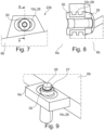
- Figure 7 shows detail VII Figure 3 and thus one of the breakpoints 22b. Similar to the bushing 24, as described above, here, however, an elongated hole bushing 28 is foamed in a form-fitting manner as a structural part 10c in a molded, one-piece extension of the partial shell 6a, b. A two-part sliding bushing 30 (in order to be able to assemble it) is slidably mounted within the elongated hole bushing 28, so that a floating bearing is created.
- Figure 8 shows the cross section along plane AA Figure 7 .
- the elongated hole bushing 28 is held firmly in the partial shell 6a, b or its extension by foaming and how the two-part sliding bushing 30 is guided in a linearly displaceable manner in the elongated hole bushing 28.
- Figure 9 shows accordingly Figure 6 , how the component 2 is screwed in a linearly movable manner to a surface (not shown) using a screw 26, which is guided through the sliding bush 30, and washer 27. Due to the comparatively large distance d2 of approximately 100cm between the two holding points 22a, noticeable changes in the length of the component 2 occur when the temperature changes, so that floating bearings with movable sliding bushes 30 are selected for screwing in order to avoid significant tension in the component 2.
- Figure 10 shows the detail X Figure 3 .
- the partial shell 6a has a spring 40 and the partial shell 6b has a corresponding groove 42.
- a plug connection 43 is thus formed.
- the spring 40 is slightly circularly convex, the groove 42 is correspondingly concave, so that it forms an undercut 44, which is engaged by the spring 40 in the assembled state M or plugged in state of the plug connection 43.
- the plug connection 43 is therefore designed as a snap connection 45.
- the snap connection 45 is sufficiently durable to hold the partial shells 6a, b together during the final assembly of the component 2.
- Figure 11 shows how to finally secure the partial shells 6a, b to one another, the component 2 contains several securing elements 46, here in the form of self-tapping screws that are screwed into the particle foam.
- the securing elements 46 are not shown in the remaining figures.
- Figure 12 again shows the partial shell 6a in the pre-assembled state.
- the component 2 contains an in Fig. 1 Covered air guide element 50, here in the form of an outlet part 52 or an outlet geometry.
- the air guiding element 50 has the plurality of outlet openings 20 of the component 2.
- the structural part 10d is also a particle foam part that was manufactured integrally together with the partial shell 6a, i.e. is integrated in one piece into the partial shell 6a.
- an air guide element 50 which would be used, for example, as an injection molded part (very different length expansion compared to particle foam) between partial shells 6a, b, no problems arise due to different length expansion of the air guide element 50 and partial shells 6a, b.
Landscapes
- Health & Medical Sciences (AREA)
- General Health & Medical Sciences (AREA)
- Pulmonology (AREA)
- Engineering & Computer Science (AREA)
- Aviation & Aerospace Engineering (AREA)
- Duct Arrangements (AREA)
- Air-Flow Control Members (AREA)
Applications Claiming Priority (3)
| Application Number | Priority Date | Filing Date | Title |
|---|---|---|---|
| DE102018007505.3A DE102018007505A1 (de) | 2018-09-24 | 2018-09-24 | Luftführungsbauteil und Herstellungsverfahren |
| EP19779786.3A EP3856638B1 (fr) | 2018-09-24 | 2019-09-24 | Conduit de ventilation et procédé pour sa fabrication |
| PCT/EP2019/075592 WO2020064665A1 (fr) | 2018-09-24 | 2019-09-24 | Élément de guidage d'air et procédé de fabrication |
Related Parent Applications (2)
| Application Number | Title | Priority Date | Filing Date |
|---|---|---|---|
| EP19779786.3A Division-Into EP3856638B1 (fr) | 2018-09-24 | 2019-09-24 | Conduit de ventilation et procédé pour sa fabrication |
| EP19779786.3A Division EP3856638B1 (fr) | 2018-09-24 | 2019-09-24 | Conduit de ventilation et procédé pour sa fabrication |
Publications (3)
| Publication Number | Publication Date |
|---|---|
| EP4328135A2 true EP4328135A2 (fr) | 2024-02-28 |
| EP4328135A3 EP4328135A3 (fr) | 2024-05-15 |
| EP4328135B1 EP4328135B1 (fr) | 2024-12-25 |
Family
ID=68104577
Family Applications (2)
| Application Number | Title | Priority Date | Filing Date |
|---|---|---|---|
| EP19779786.3A Active EP3856638B1 (fr) | 2018-09-24 | 2019-09-24 | Conduit de ventilation et procédé pour sa fabrication |
| EP24151828.1A Active EP4328135B1 (fr) | 2018-09-24 | 2019-09-24 | Composant de guidage d'air |
Family Applications Before (1)
| Application Number | Title | Priority Date | Filing Date |
|---|---|---|---|
| EP19779786.3A Active EP3856638B1 (fr) | 2018-09-24 | 2019-09-24 | Conduit de ventilation et procédé pour sa fabrication |
Country Status (4)
| Country | Link |
|---|---|
| US (1) | US12208905B2 (fr) |
| EP (2) | EP3856638B1 (fr) |
| DE (1) | DE102018007505A1 (fr) |
| WO (1) | WO2020064665A1 (fr) |
Families Citing this family (1)
| Publication number | Priority date | Publication date | Assignee | Title |
|---|---|---|---|---|
| DE102022000756A1 (de) | 2022-03-03 | 2023-09-07 | Truma Gerätetechnik GmbH & Co. KG | Klimagerät |
Citations (8)
| Publication number | Priority date | Publication date | Assignee | Title |
|---|---|---|---|---|
| EP1299219B1 (fr) | 2000-07-12 | 2004-10-06 | Fraunhofer-Gesellschaft zur Förderung der angewandten Forschung e.V. | Procede de fabrication de pieces moulees en mousse particulaire dotees d'une couche de couverture |
| EP1959209A2 (fr) | 2007-02-19 | 2008-08-20 | MAICO ELEKTROAPPARATE-FABRIK GmbH | Unité de commande et/ou de réglage destinée au dosage d'un flux d'air, système d'aération |
| DE102008050546A1 (de) | 2008-10-06 | 2010-04-15 | Airbus Deutschland Gmbh | Side-Feeder-Luftführungselement für eine Flugzeugklimaanlage |
| DE202012004525U1 (de) | 2012-05-09 | 2012-07-30 | Ruch Novaplast Gmbh + Co. Kg | Revisionsklappensystem |
| US20120248839A1 (en) | 2009-10-05 | 2012-10-04 | Delta Tooling Co., Ltd. | Cushion structure and vehicle seat |
| DE102013002893A1 (de) | 2013-02-20 | 2014-08-21 | Diehl Aircabin Gmbh | Hybridbauteil und Herstellungsverfahren |
| WO2016004522A1 (fr) | 2014-07-11 | 2016-01-14 | Exo-S Inc. | Gaine d'air légère pour la ventilation, la climatisation et le chauffage destinée à être utilisée dans un véhicule et procédé de fabrication de cette dernière |
| DE102016121366A1 (de) | 2016-11-08 | 2018-05-09 | Airbus Operations Gmbh | Verkleidungs-paneel und verfahren zum herstellen eines verkleidungs-paneels |
Family Cites Families (2)
| Publication number | Priority date | Publication date | Assignee | Title |
|---|---|---|---|---|
| US6752712B1 (en) * | 2003-02-10 | 2004-06-22 | The Boeing, Company | Slotted air distribution nozzle restrictor assembly |
| WO2019038213A1 (fr) | 2017-08-24 | 2019-02-28 | Evonik Röhm Gmbh | Mousses à base de particules de pei destinées à des utilisations à l'intérieur d'avions |
-
2018
- 2018-09-24 DE DE102018007505.3A patent/DE102018007505A1/de not_active Withdrawn
-
2019
- 2019-09-24 EP EP19779786.3A patent/EP3856638B1/fr active Active
- 2019-09-24 WO PCT/EP2019/075592 patent/WO2020064665A1/fr not_active Ceased
- 2019-09-24 EP EP24151828.1A patent/EP4328135B1/fr active Active
-
2021
- 2021-03-19 US US17/206,500 patent/US12208905B2/en active Active
Patent Citations (8)
| Publication number | Priority date | Publication date | Assignee | Title |
|---|---|---|---|---|
| EP1299219B1 (fr) | 2000-07-12 | 2004-10-06 | Fraunhofer-Gesellschaft zur Förderung der angewandten Forschung e.V. | Procede de fabrication de pieces moulees en mousse particulaire dotees d'une couche de couverture |
| EP1959209A2 (fr) | 2007-02-19 | 2008-08-20 | MAICO ELEKTROAPPARATE-FABRIK GmbH | Unité de commande et/ou de réglage destinée au dosage d'un flux d'air, système d'aération |
| DE102008050546A1 (de) | 2008-10-06 | 2010-04-15 | Airbus Deutschland Gmbh | Side-Feeder-Luftführungselement für eine Flugzeugklimaanlage |
| US20120248839A1 (en) | 2009-10-05 | 2012-10-04 | Delta Tooling Co., Ltd. | Cushion structure and vehicle seat |
| DE202012004525U1 (de) | 2012-05-09 | 2012-07-30 | Ruch Novaplast Gmbh + Co. Kg | Revisionsklappensystem |
| DE102013002893A1 (de) | 2013-02-20 | 2014-08-21 | Diehl Aircabin Gmbh | Hybridbauteil und Herstellungsverfahren |
| WO2016004522A1 (fr) | 2014-07-11 | 2016-01-14 | Exo-S Inc. | Gaine d'air légère pour la ventilation, la climatisation et le chauffage destinée à être utilisée dans un véhicule et procédé de fabrication de cette dernière |
| DE102016121366A1 (de) | 2016-11-08 | 2018-05-09 | Airbus Operations Gmbh | Verkleidungs-paneel und verfahren zum herstellen eines verkleidungs-paneels |
Also Published As
| Publication number | Publication date |
|---|---|
| US20210206496A1 (en) | 2021-07-08 |
| EP3856638B1 (fr) | 2024-03-13 |
| EP4328135B1 (fr) | 2024-12-25 |
| US12208905B2 (en) | 2025-01-28 |
| DE102018007505A1 (de) | 2020-03-26 |
| WO2020064665A1 (fr) | 2020-04-02 |
| EP3856638A1 (fr) | 2021-08-04 |
| EP4328135A3 (fr) | 2024-05-15 |
Similar Documents
| Publication | Publication Date | Title |
|---|---|---|
| EP2411280B1 (fr) | Structure d'avion avec compartiments de guidage d'air intégrés dans les éléments structuraux | |
| WO2012003964A1 (fr) | Système support d'éléments intérieurs, module d'éléments intérieurs d'aéronef et procédé de montage | |
| EP2563653A1 (fr) | Système de rails, et procédé et système pour monter une pièce dans un avion | |
| EP2560865B1 (fr) | Élément d'équipement intérieur d'avion et système d'éléments d'équipement intérieur d'avion | |
| DE102006028956A1 (de) | Flugzeugseitenverkleidung | |
| DE102007008987B4 (de) | Rumpf eines Luft-oder Raumfahrzeugs sowie ein Verfahren zum aktiven Isolieren eines solchen Rumpfes | |
| DE102008025959B4 (de) | Vorrichtung zur Verbindung von zwei Rohrleitungselementen und einer Blende in einer Flugzeugklimatisierungsanlage | |
| DE29712909U1 (de) | Selbsttätig schließende Brandschutzeinrichtung | |
| EP3856638B1 (fr) | Conduit de ventilation et procédé pour sa fabrication | |
| DE102010026839A1 (de) | Aerodynamische Verkleidungsvorrichtung, Flugzeug-Bauteilanordnung mit einer aerodynamischen Verkleidungsvorrichtung sowie Verfahren zur Montage eines solchen Verkleidungsteils | |
| DE102018121562A1 (de) | Verfahren zum Herstellen eines insbesondere flexiblen Verteilerrohres | |
| EP3233546B1 (fr) | Procédé de fabrication d'un élément structural de carrosserie pour un véhicule automobile, dispositif de fabrication d'un élément structural de carrosserie pour un véhicule automobile, et élément structural de carrosserie pour un véhicule automobile | |
| DE102017117274A1 (de) | Gepäckfach zur rumpf- oder deckenseitigen Installation in einem Fahrzeug und Verfahren zum Herstellen eines derartigen Gepäckfachs | |
| EP3599169B1 (fr) | Module mélangeur pourvu d'un élément filtrant environnant, espace de rangement pourvu du module mélangeur, véhicule doté d'un espace de rangement et procédé d'installation d'un module mélangeur | |
| DE102007061253A1 (de) | Flugzeugrumpfelement | |
| DE102018115776A1 (de) | Sitzgestellbefestigungsbaugruppe, Sitzgestell, Fahrzeugabschnitt und Fahrzeug mit einer Sitzgestellbefestigungsbaugruppe | |
| DE102010055995A1 (de) | Flugzeugsystemkomponententrägersystem und Montageverfahren | |
| DE202007012988U1 (de) | Mehrkanalige Luftführungsvorrichtung | |
| DE102013100308A1 (de) | Riegelstangenbeschlag für ein Fenster oder eine Tür | |
| DE102012223864B3 (de) | Vorrichtung zur Aufnahme mindestens einer Komponente eines SOFC-Brennstoffzellensystems und Verfahren zur Herstellung einer solchen Vorrichtung | |
| DE102017203563A1 (de) | Verfahren zum Herstellen einer Ventilanordnung | |
| EP2403755B1 (fr) | Système d'assemblage et module adaptateur associé | |
| DE102014113615B4 (de) | Klappe für ein Klimagerät | |
| WO2019171243A1 (fr) | Module de canal pour systèmes de répartition d'air | |
| DE10150154A1 (de) | Klimatisierungseinrichtung eines Fahrzeugs |
Legal Events
| Date | Code | Title | Description |
|---|---|---|---|
| PUAI | Public reference made under article 153(3) epc to a published international application that has entered the european phase |
Free format text: ORIGINAL CODE: 0009012 |
|
| STAA | Information on the status of an ep patent application or granted ep patent |
Free format text: STATUS: THE APPLICATION HAS BEEN PUBLISHED |
|
| AC | Divisional application: reference to earlier application |
Ref document number: 3856638 Country of ref document: EP Kind code of ref document: P |
|
| AK | Designated contracting states |
Kind code of ref document: A2 Designated state(s): AL AT BE BG CH CY CZ DE DK EE ES FI FR GB GR HR HU IE IS IT LI LT LU LV MC MK MT NL NO PL PT RO RS SE SI SK SM TR |
|
| PUAL | Search report despatched |
Free format text: ORIGINAL CODE: 0009013 |
|
| STAA | Information on the status of an ep patent application or granted ep patent |
Free format text: STATUS: REQUEST FOR EXAMINATION WAS MADE |
|
| AK | Designated contracting states |
Kind code of ref document: A3 Designated state(s): AL AT BE BG CH CY CZ DE DK EE ES FI FR GB GR HR HU IE IS IT LI LT LU LV MC MK MT NL NO PL PT RO RS SE SI SK SM TR |
|
| RIC1 | Information provided on ipc code assigned before grant |
Ipc: B64D 13/00 20060101AFI20240410BHEP |
|
| 17P | Request for examination filed |
Effective date: 20240429 |
|
| RBV | Designated contracting states (corrected) |
Designated state(s): AL AT BE BG CH CY CZ DE DK EE ES FI FR GB GR HR HU IE IS IT LI LT LU LV MC MK MT NL NO PL PT RO RS SE SI SK SM TR |
|
| GRAP | Despatch of communication of intention to grant a patent |
Free format text: ORIGINAL CODE: EPIDOSNIGR1 |
|
| STAA | Information on the status of an ep patent application or granted ep patent |
Free format text: STATUS: GRANT OF PATENT IS INTENDED |
|
| INTG | Intention to grant announced |
Effective date: 20241001 |
|
| GRAS | Grant fee paid |
Free format text: ORIGINAL CODE: EPIDOSNIGR3 |
|
| GRAA | (expected) grant |
Free format text: ORIGINAL CODE: 0009210 |
|
| STAA | Information on the status of an ep patent application or granted ep patent |
Free format text: STATUS: THE PATENT HAS BEEN GRANTED |
|
| AC | Divisional application: reference to earlier application |
Ref document number: 3856638 Country of ref document: EP Kind code of ref document: P |
|
| AK | Designated contracting states |
Kind code of ref document: B1 Designated state(s): AL AT BE BG CH CY CZ DE DK EE ES FI FR GB GR HR HU IE IS IT LI LT LU LV MC MK MT NL NO PL PT RO RS SE SI SK SM TR |
|
| REG | Reference to a national code |
Ref country code: GB Ref legal event code: FG4D Free format text: NOT ENGLISH |
|
| REG | Reference to a national code |
Ref country code: CH Ref legal event code: EP |
|
| REG | Reference to a national code |
Ref country code: DE Ref legal event code: R096 Ref document number: 502019012712 Country of ref document: DE |
|
| REG | Reference to a national code |
Ref country code: IE Ref legal event code: FG4D Free format text: LANGUAGE OF EP DOCUMENT: GERMAN |
|
| REG | Reference to a national code |
Ref country code: LT Ref legal event code: MG9D |
|
| PG25 | Lapsed in a contracting state [announced via postgrant information from national office to epo] |
Ref country code: HR Free format text: LAPSE BECAUSE OF FAILURE TO SUBMIT A TRANSLATION OF THE DESCRIPTION OR TO PAY THE FEE WITHIN THE PRESCRIBED TIME-LIMIT Effective date: 20241225 |
|
| PG25 | Lapsed in a contracting state [announced via postgrant information from national office to epo] |
Ref country code: FI Free format text: LAPSE BECAUSE OF FAILURE TO SUBMIT A TRANSLATION OF THE DESCRIPTION OR TO PAY THE FEE WITHIN THE PRESCRIBED TIME-LIMIT Effective date: 20241225 |
|
| PG25 | Lapsed in a contracting state [announced via postgrant information from national office to epo] |
Ref country code: BG Free format text: LAPSE BECAUSE OF FAILURE TO SUBMIT A TRANSLATION OF THE DESCRIPTION OR TO PAY THE FEE WITHIN THE PRESCRIBED TIME-LIMIT Effective date: 20241225 |
|
| PG25 | Lapsed in a contracting state [announced via postgrant information from national office to epo] |
Ref country code: NO Free format text: LAPSE BECAUSE OF FAILURE TO SUBMIT A TRANSLATION OF THE DESCRIPTION OR TO PAY THE FEE WITHIN THE PRESCRIBED TIME-LIMIT Effective date: 20250325 |
|
| PG25 | Lapsed in a contracting state [announced via postgrant information from national office to epo] |
Ref country code: GR Free format text: LAPSE BECAUSE OF FAILURE TO SUBMIT A TRANSLATION OF THE DESCRIPTION OR TO PAY THE FEE WITHIN THE PRESCRIBED TIME-LIMIT Effective date: 20250326 Ref country code: LV Free format text: LAPSE BECAUSE OF FAILURE TO SUBMIT A TRANSLATION OF THE DESCRIPTION OR TO PAY THE FEE WITHIN THE PRESCRIBED TIME-LIMIT Effective date: 20241225 |
|
| PG25 | Lapsed in a contracting state [announced via postgrant information from national office to epo] |
Ref country code: RS Free format text: LAPSE BECAUSE OF FAILURE TO SUBMIT A TRANSLATION OF THE DESCRIPTION OR TO PAY THE FEE WITHIN THE PRESCRIBED TIME-LIMIT Effective date: 20250325 |
|
| REG | Reference to a national code |
Ref country code: NL Ref legal event code: MP Effective date: 20241225 |
|
| PG25 | Lapsed in a contracting state [announced via postgrant information from national office to epo] |
Ref country code: NL Free format text: LAPSE BECAUSE OF FAILURE TO SUBMIT A TRANSLATION OF THE DESCRIPTION OR TO PAY THE FEE WITHIN THE PRESCRIBED TIME-LIMIT Effective date: 20241225 |
|
| PG25 | Lapsed in a contracting state [announced via postgrant information from national office to epo] |
Ref country code: SM Free format text: LAPSE BECAUSE OF FAILURE TO SUBMIT A TRANSLATION OF THE DESCRIPTION OR TO PAY THE FEE WITHIN THE PRESCRIBED TIME-LIMIT Effective date: 20241225 |
|
| PG25 | Lapsed in a contracting state [announced via postgrant information from national office to epo] |
Ref country code: PL Free format text: LAPSE BECAUSE OF FAILURE TO SUBMIT A TRANSLATION OF THE DESCRIPTION OR TO PAY THE FEE WITHIN THE PRESCRIBED TIME-LIMIT Effective date: 20241225 |
|
| PG25 | Lapsed in a contracting state [announced via postgrant information from national office to epo] |
Ref country code: ES Free format text: LAPSE BECAUSE OF FAILURE TO SUBMIT A TRANSLATION OF THE DESCRIPTION OR TO PAY THE FEE WITHIN THE PRESCRIBED TIME-LIMIT Effective date: 20241225 |
|
| PG25 | Lapsed in a contracting state [announced via postgrant information from national office to epo] |
Ref country code: IS Free format text: LAPSE BECAUSE OF FAILURE TO SUBMIT A TRANSLATION OF THE DESCRIPTION OR TO PAY THE FEE WITHIN THE PRESCRIBED TIME-LIMIT Effective date: 20250425 |
|
| PG25 | Lapsed in a contracting state [announced via postgrant information from national office to epo] |
Ref country code: PT Free format text: LAPSE BECAUSE OF FAILURE TO SUBMIT A TRANSLATION OF THE DESCRIPTION OR TO PAY THE FEE WITHIN THE PRESCRIBED TIME-LIMIT Effective date: 20250428 |
|
| PG25 | Lapsed in a contracting state [announced via postgrant information from national office to epo] |
Ref country code: EE Free format text: LAPSE BECAUSE OF FAILURE TO SUBMIT A TRANSLATION OF THE DESCRIPTION OR TO PAY THE FEE WITHIN THE PRESCRIBED TIME-LIMIT Effective date: 20241225 |
|
| PG25 | Lapsed in a contracting state [announced via postgrant information from national office to epo] |
Ref country code: RO Free format text: LAPSE BECAUSE OF FAILURE TO SUBMIT A TRANSLATION OF THE DESCRIPTION OR TO PAY THE FEE WITHIN THE PRESCRIBED TIME-LIMIT Effective date: 20241225 |
|
| PG25 | Lapsed in a contracting state [announced via postgrant information from national office to epo] |
Ref country code: SK Free format text: LAPSE BECAUSE OF FAILURE TO SUBMIT A TRANSLATION OF THE DESCRIPTION OR TO PAY THE FEE WITHIN THE PRESCRIBED TIME-LIMIT Effective date: 20241225 |
|
| PG25 | Lapsed in a contracting state [announced via postgrant information from national office to epo] |
Ref country code: CZ Free format text: LAPSE BECAUSE OF FAILURE TO SUBMIT A TRANSLATION OF THE DESCRIPTION OR TO PAY THE FEE WITHIN THE PRESCRIBED TIME-LIMIT Effective date: 20241225 |
|
| PG25 | Lapsed in a contracting state [announced via postgrant information from national office to epo] |
Ref country code: IT Free format text: LAPSE BECAUSE OF FAILURE TO SUBMIT A TRANSLATION OF THE DESCRIPTION OR TO PAY THE FEE WITHIN THE PRESCRIBED TIME-LIMIT Effective date: 20241225 |
|
| PG25 | Lapsed in a contracting state [announced via postgrant information from national office to epo] |
Ref country code: SE Free format text: LAPSE BECAUSE OF FAILURE TO SUBMIT A TRANSLATION OF THE DESCRIPTION OR TO PAY THE FEE WITHIN THE PRESCRIBED TIME-LIMIT Effective date: 20241225 |
|
| REG | Reference to a national code |
Ref country code: DE Ref legal event code: R097 Ref document number: 502019012712 Country of ref document: DE |
|
| PG25 | Lapsed in a contracting state [announced via postgrant information from national office to epo] |
Ref country code: DK Free format text: LAPSE BECAUSE OF FAILURE TO SUBMIT A TRANSLATION OF THE DESCRIPTION OR TO PAY THE FEE WITHIN THE PRESCRIBED TIME-LIMIT Effective date: 20241225 |
|
| PGFP | Annual fee paid to national office [announced via postgrant information from national office to epo] |
Ref country code: FR Payment date: 20250922 Year of fee payment: 7 |
|
| PLBE | No opposition filed within time limit |
Free format text: ORIGINAL CODE: 0009261 |
|
| STAA | Information on the status of an ep patent application or granted ep patent |
Free format text: STATUS: NO OPPOSITION FILED WITHIN TIME LIMIT |
|
| REG | Reference to a national code |
Ref country code: CH Ref legal event code: L10 Free format text: ST27 STATUS EVENT CODE: U-0-0-L10-L00 (AS PROVIDED BY THE NATIONAL OFFICE) Effective date: 20251105 |
|
| 26N | No opposition filed |
Effective date: 20250926 |
|
| PGFP | Annual fee paid to national office [announced via postgrant information from national office to epo] |
Ref country code: DE Payment date: 20251106 Year of fee payment: 7 |
|
| REG | Reference to a national code |
Ref country code: CH Ref legal event code: H13 Free format text: ST27 STATUS EVENT CODE: U-0-0-H10-H13 (AS PROVIDED BY THE NATIONAL OFFICE) Effective date: 20260425 |