EP4328135B1 - Luftführungsbauteil - Google Patents
Luftführungsbauteil Download PDFInfo
- Publication number
- EP4328135B1 EP4328135B1 EP24151828.1A EP24151828A EP4328135B1 EP 4328135 B1 EP4328135 B1 EP 4328135B1 EP 24151828 A EP24151828 A EP 24151828A EP 4328135 B1 EP4328135 B1 EP 4328135B1
- Authority
- EP
- European Patent Office
- Prior art keywords
- component
- air
- shells
- foam
- particle
- Prior art date
- Legal status (The legal status is an assumption and is not a legal conclusion. Google has not performed a legal analysis and makes no representation as to the accuracy of the status listed.)
- Active
Links
Images



Classifications
-
- B—PERFORMING OPERATIONS; TRANSPORTING
- B64—AIRCRAFT; AVIATION; COSMONAUTICS
- B64D—EQUIPMENT FOR FITTING IN OR TO AIRCRAFT; FLIGHT SUITS; PARACHUTES; ARRANGEMENT OR MOUNTING OF POWER PLANTS OR PROPULSION TRANSMISSIONS IN AIRCRAFT
- B64D13/00—Arrangements or adaptations of air-treatment apparatus for aircraft crew or passengers, or freight space
-
- B—PERFORMING OPERATIONS; TRANSPORTING
- B64—AIRCRAFT; AVIATION; COSMONAUTICS
- B64D—EQUIPMENT FOR FITTING IN OR TO AIRCRAFT; FLIGHT SUITS; PARACHUTES; ARRANGEMENT OR MOUNTING OF POWER PLANTS OR PROPULSION TRANSMISSIONS IN AIRCRAFT
- B64D13/00—Arrangements or adaptations of air-treatment apparatus for aircraft crew or passengers, or freight space
- B64D13/06—Arrangements or adaptations of air-treatment apparatus for aircraft crew or passengers, or freight space the air being conditioned
-
- B—PERFORMING OPERATIONS; TRANSPORTING
- B29—WORKING OF PLASTICS; WORKING OF SUBSTANCES IN A PLASTIC STATE IN GENERAL
- B29C—SHAPING OR JOINING OF PLASTICS; SHAPING OF MATERIAL IN A PLASTIC STATE, NOT OTHERWISE PROVIDED FOR; AFTER-TREATMENT OF THE SHAPED PRODUCTS, e.g. REPAIRING
- B29C44/00—Shaping by internal pressure generated in the material, e.g. swelling or foaming ; Producing porous or cellular expanded plastics articles
- B29C44/34—Auxiliary operations
- B29C44/36—Feeding the material to be shaped
- B29C44/38—Feeding the material to be shaped into a closed space, i.e. to make articles of definite length
- B29C44/44—Feeding the material to be shaped into a closed space, i.e. to make articles of definite length in solid form
- B29C44/445—Feeding the material to be shaped into a closed space, i.e. to make articles of definite length in solid form in the form of expandable granules, particles or beads
-
- B—PERFORMING OPERATIONS; TRANSPORTING
- B29—WORKING OF PLASTICS; WORKING OF SUBSTANCES IN A PLASTIC STATE IN GENERAL
- B29L—INDEXING SCHEME ASSOCIATED WITH SUBCLASS B29C, RELATING TO PARTICULAR ARTICLES
- B29L2031/00—Other particular articles
- B29L2031/30—Vehicles, e.g. ships or aircraft, or body parts thereof
- B29L2031/3076—Aircrafts
-
- Y—GENERAL TAGGING OF NEW TECHNOLOGICAL DEVELOPMENTS; GENERAL TAGGING OF CROSS-SECTIONAL TECHNOLOGIES SPANNING OVER SEVERAL SECTIONS OF THE IPC; TECHNICAL SUBJECTS COVERED BY FORMER USPC CROSS-REFERENCE ART COLLECTIONS [XRACs] AND DIGESTS
- Y02—TECHNOLOGIES OR APPLICATIONS FOR MITIGATION OR ADAPTATION AGAINST CLIMATE CHANGE
- Y02T—CLIMATE CHANGE MITIGATION TECHNOLOGIES RELATED TO TRANSPORTATION
- Y02T50/00—Aeronautics or air transport
- Y02T50/40—Weight reduction
Definitions
- the invention relates to a component for air guidance for an air conditioning system of an aircraft.
- air duct components in aircraft have been made from fiber-reinforced plastics (carbon or glass fiber in a plastic matrix), as a sandwich structure (fiber components and honeycomb structures) or in a hybrid construction (carbon and glass fiber in a plastic matrix).
- Complex components are made from several individual components that are laboriously joined together.
- Two half shells are created, which are glued together in a subsequent process step together with the necessary attachments and installation parts.
- a cladding panel with a panel element, a rectangular opening and a flap is known.
- the cladding panel has a flap which can be rotated about a joint which is integrated into the panel element in order to open and/or close the rectangular opening.
- U1 is an inspection flap system for reversibly closing an opening in a housing, wall or ceiling panel with a frame and a lockable flap.
- the frame and the lockable flap is made of particle foam and is integrated into a housing, wall or ceiling element, which is also made of particle foam.
- An air duct component for an air conditioning system of a vehicle is known, which is formed from two partial shells, which in turn are particle-forming parts.
- An air guide component which comprises a housing with an air duct.
- the housing can be made up of several parts, whereby the individual parts can be made of particle foam.
- the DE 10 2008 050 546 A1 discloses an air guide element for an aircraft air conditioning system, comprising a distributor pipe which has an air inlet opening arranged in the region of an end face of the distributor pipe and an air discharge opening arranged in the region of a jacket surface of the distributor pipe.
- An air duct component for an air conditioning system of an aircraft is known, which is made of a fiber composite plastic and a plastic foam.
- the object of the present invention is to propose improvements with regard to air guiding components.
- the component is used to guide air, i.e. to direct air.
- the air is guided inside or in an aircraft's air conditioning system.
- Such components are also called air duct or climate components.
- the component has at least one inlet opening for air and at least one outlet opening for air.
- exactly one inlet opening is provided.
- exactly one outlet opening or several outlet openings e.g. also three, four or a plurality, are provided.
- the component contains at least two partial shells, in particular exactly two partial shells, in particular in the form of half shells.
- the partial shells are connected to one another in an airtight manner when the component is assembled or finished. During or after the connection, the inlet and outlet openings remain free so that the component can fulfil its function of internal air guidance from the inlet openings to the outlet openings.
- the partial shells are particle foam parts, i.e. they are made from particle foam during their production.
- the aircraft is in particular a passenger aircraft.
- the component is in particular intended for the interior of the aircraft or is mounted there in an installed state.
- the interior is in particular a passenger cabin.
- the component is in particular an air outlet component, i.e. the air outlets open into a free space, in particular the interior of the aircraft.
- particle foam not only saves weight but also generally shortens the manufacturing process times.
- the components mentioned above are manufactured in a hot press, which requires a process time of around 15 minutes.
- Particle foaming takes around 5 minutes for a comparable component.
- the invention is based on the finding that the foaming of materials results in a material group of particle foams which, due to their special structure and associated properties, opens up possibilities for use in other ways and thus new fields of application.
- the desired properties of the foam can be achieved.
- particle foams promises enormous potential for lightweight construction within the group of polymer foams, as their main component is over 90% air.
- the density of a particle foam can currently be varied in a range of 8 - 200 g/l. This can influence other properties such as mechanical properties or thermal insulation capacity.
- the component contains at least one structural part.
- Structural parts can be used to create components with a wide variety of variants that would not be possible using the partial shells alone.
- At least one of the structural parts is an end sleeve forming or containing the inlet opening or attached to the inlet opening.
- the component can be connected to further air duct components.
- the end sleeve is secured in the component by being positively received between at least two of the partial shells, whereby the end sleeve can be positively inserted between the partial shells when they are joined together.
- the corresponding partial shells thus form a positive connection together with the end sleeve - in particular thanks to fits, projections, undercuts, grooves, springs, etc. formed on the respective components.
- an end sleeve serves in particular as a connecting piece to the adjacent or air-supplying pipe.
- the end sleeve is manufactured, for example, as an injection-molded part and inserted into a half-shell before the joining process.
- a captive connection is created between the end sleeve and the air outlet.
- a collar on the sleeve that ensures a positive connection (together with a counterpart in the partial shells) transfers moments to the air outlet and/or simultaneously provides an anti-twist device.
- the end sleeve has a collar that engages in a groove in the partial shells.
- an anti-twisting device is implemented between the component and the end sleeve.
- a further structural part is an air guiding element that guides air in and/or on the component. In this way, desired air guiding properties can be achieved in and/or on the component.
- the air guide element is an outlet part that forms at least one, in particular all, of the outlet openings.
- the outlet part is in particular an outlet grille.
- the grille openings form the outlet openings.
- Outlet grilles are particularly established as outlet parts.
- the structural part is a particle foam part.
- the particle foam technology is therefore used not only for the partial shells, but also for the structural parts, which is why the corresponding advantages also apply to structural parts.
- the structural part is integrated in one piece into one of the partial shells. This enables the structural part and partial shell to be manufactured together as a single, integrated component. In addition, the final assembly of the entire component can be made easier, as fewer individual parts have to be handled.
- a further structural part is a structural part that is foamed into the particle foam of a partial shell and is not a particle foam part. This makes it possible to also include structural parts that would not be possible or would be difficult or inadequate to realize as particle foam parts. This applies in particular to metallic structural parts and/or mounting elements as structural parts.
- the structural part is a bushing or an elongated hole bushing.
- the elongated hole bushing contains in particular a sliding bushing that can slide along the elongated hole.
- a corresponding bushing serves as a fixed bearing, a corresponding elongated hole bushing with a sliding bushing as a floating bearing for the component.
- dimensional changes due to thermal expansion between the component and the substrate on which the component is attached can be compensated. It should be remembered that, particularly in the aviation sector, temperature ranges of -55°C to +88°C must be taken into account.
- At least two of the partial shells have a detachable plug connection for connecting them to one another.
- the plug connection is in particular placed on the edge of the partial shells.
- the corresponding connection is also made of particle foam.
- the connection is a tongue and groove connection.
- the plug connection or its components are thus an integral part of the respective partial shells and are therefore particularly easy and inexpensive to manufacture. During final assembly, no additional connecting/sealing parts are required to connect and/or seal the two partial shells to one another.
- the plug connection is dimensioned with a slight oversize and the elastic properties of the particle foam are used to create a plug connection that has a certain holding force.
- the plug connection is a snap connection (e.g. "snap and click") with an undercut that engages when plugged in.
- the groove has the undercut that is engaged by a projection of the tongue.
- the elastic properties of the particle foam are used to achieve the flexibility required for the snap connection.
- a corresponding snap connection has an increased holding force compared to a tongue and groove connection without an undercut.
- the component contains a securing element that fixes at least two of the partial shells together.
- a securing element is, for example, a clamp connection, a screw connection, a screw cutting into the particle foam, etc.
- the securing element is implemented as an alternative or in addition to the above-mentioned plug/snap connection.
- the particle foam is expanding polypropylene (EPP). This material is particularly suitable for the corresponding application.
- the invention is based on the following findings, observations and considerations and also has the following embodiments.
- the invention is based on the idea of developing air duct components for air conditioning systems in aircraft made of particle foam that meet the requirements of aviation.
- the idea is also to integrate as many functions of the component as possible into the manufacturing process in order to achieve fast and cost-effective production.
- the very different thermal properties between particle foam and fiber-reinforced plastics due to the wide temperature range of the aircraft, which can lead to internal stresses in the foam component and to cracks in its structure, are to be considered and suitable measures to compensate for the thermal effects are to be developed.
- the components consist of two separately foamed half-shells made of expanding polypropylene (EPP).
- EPP expanding polypropylene
- separately manufactured components structural parts, (long hole) bushings
- These components serve as a hard support, defined guide for the fastening element and tear-out protection for the particle foam and are foamed around the half-shell in a positionally precise, form-fitting and loss-proof manner during the foaming process.
- the internal functional elements for air guidance can be foamed together with the half-shells in the same process step. It is possible to reproduce the elements completely in a half-shell or only a part of them in each half-shell and to connect them together in the subsequent joining process.
- the foamed-in support elements described above are designed in appropriate positions with a translational degree of freedom for an additional plain bearing (sliding bush) mounted in them. These plain bearings can move in them and accordingly generate a loose bearing with a translational degree of freedom, which can compensate for the different thermal linear expansions of the materials.
- the joint seam is designed as a tongue and groove connection between the two half shells, so that a plug connection is created that can initially be removed.
- a plug connection is created that can initially be removed.
- a stable connection including airtightness is achieved simply by plugging them into one another.
- the properties of the foam in terms of deformability and recovery behavior are exploited.
- the two half shells can also be fixed using additional securing elements.
- a groove is provided in the particle foam half-shells so that no subsequent, complex process step (such as gluing) is necessary for the insertion of an end sleeve as a connecting piece to the adjacent pipeline.
- the end sleeve has a web (collar) corresponding to the groove and is inserted into the groove during the joining process of the two half-shells. The joining of the half-shells creates a captive connection.
- the new technology of air duct components in particle foam means that when the air outlets are assembled with the components (hat rack, secondary structure, primary structure) on which they are mounted, a combination of materials with very different thermal expansion coefficients is created. This leads to a linear expansion of the foam components that is increased by a factor of up to five or more. These differences generate internal stresses in the foam component and can lead to cracks in its structure.
- long hole bushings are integrated into the manufacturing process of the air outlet half shells. These long hole bushings are sized to accommodate the length expansion. Sliding bushings are mounted in these long hole bushings, thus generating a floating bearing with a translational degree of freedom. The air outlet is then attached using screws through the sliding bushings, for example.
- an air outlet is produced in particle foam, consisting of two half shells. Additional components for holding and simultaneously compensating for thermal expansion effects are integrated into the shells, as well as the representation of various air flow geometries in particle foam.
- the shells are inserted into one another using a tongue and groove connection and secured using additional securing elements.
- EPP particle foam construction
- the invention offers the advantages of weight reduction, cost reduction, improvement of process times, an integrated manufacturing method and the application of a new technology.
- the invention is used, for example, for a single aisle ceiling air outlet or a single aisle side air outlet.
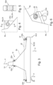
- Figure 1 shows a component 2 for guiding air 4 (in operation), indicated by an arrow.
- the component 2 is a component for an air conditioning system of an aircraft (not shown in more detail).
- the component 2 contains two partial shells 6a,b, here in the form of half shells.
- the partial shells 6a,b are particle foam parts, ie manufactured or produced from particle foam.
- Figure 1 shows a pre-assembly position, ie the two partial shells 6a,b are not yet joined together. For assembly, the parts are moved towards each other in the direction of the arrows 8 and connected to each other in an airtight manner to form component 2 (at their edges, leaving out inlet and outlet openings for air 4, see below).
- the component 2 contains a structural part 10a, here an end sleeve 12.
- the end sleeve 12 serves as a connecting piece of the component 2 to an adjacent pipe, not shown.
- the air 4 is guided through the end sleeve 12 into the component 2.
- the end sleeve 12 is inserted into the partial shell 6a or 6b.
- the end sleeve 12 has a collar 14.
- the partial shells 6a,b have a corresponding groove 16 for receiving the collar 14.
- Figure 2 shows the detail II from Figure 1 after the joining process in cross-section along the plane AA and thus the assembly state M of the component 2.
- the component 2 now has an inlet opening 18 for the air 4.
- the end sleeve 12 also has the inlet opening 18 or the end sleeve 12 lies in the inlet opening 18.
- Figure 3 shows the entire component 2 in the assembled state M, but omitting the end sleeve 12.
- the component 2 has a plurality of outlet openings 20 for the air 4, which are explained in more detail below.
- the component 2 also has a total of four holding points 22a,b.
- the holding points 22a,b are each located on unspecified extensions or formations of the component 2.
- Two holding points 22a are designed as fixed bearings, two holding points 22b as floating bearings.
- Figure 4 shows one of the stopping points 22a in detail IV from Figure 3
- the holding point 22a is formed in that the extension was manufactured in one piece from particle foam during the manufacture of the partial shells 6a and/or 6b and a further structural part 10b, here a bushing 24, was foamed into the particle foam.
- Figure 5 shows the cross section along the plane AA through Figure 4 Here it can be seen how the bushing 24 is held firmly in the partial shell 6a,b or its extension by foaming.
- Figure 6 shows how the component 2 is fixed to a non-illustrated base using a screw 26, which is guided through the bushing 24, and a washer 27 underneath is screwed. Due to the comparatively small distance d1 of approximately 10 cm between the two holding points 22a, there are hardly any changes in the length of the component 2 when the temperature changes, so that fixed bushings 24 are sufficient for screwing without causing any significant tension in the component 2.
- Figure 7 shows detail VII from Figure 3 and thus one of the holding points 22b.
- an elongated hole bushing 28 is foamed into a molded, one-piece extension of the partial shell 6a,b.
- a two-part sliding bushing 30 (in order to be able to mount it) is slidably mounted within the elongated hole bushing 28, so that a loose bearing is created.
- Figure 8 shows the cross section along the plane AA through Figure 7 Here it can be seen how the elongated hole bushing 28 is firmly held in the partial shell 6a,b or its extension by foaming and how the two-part sliding bushing 30 is guided in the elongated hole bushing 28 so as to be linearly displaceable.
- Figure 9 shows accordingly Figure 6 how the component 2 is screwed to a base (not shown) in a linearly movable manner using a screw 26, which is guided through the sliding bushing 30, and a disk 27. Due to the comparatively large distance d2 of approx. 100cm between the two holding points 22a, noticeable changes in the length of the component 2 occur when the temperature changes, so that loose bearings with movable sliding bushings 30 are selected for screwing in order to avoid significant tension in the component 2.
- Figure 10 shows the detail X from Figure 3 .
- the partial shell 6a has a spring 40 and the partial shell 6b has a corresponding groove 42.
- the spring 40 is slightly circularly convex, the groove 42 is correspondingly concave, so that it forms an undercut 44, which is gripped behind by the spring 40 in the assembled state M or plugged state of the plug connection 43.
- the plug connection 43 is thus designed as a snap connection 45.
- the snap connection 45 is sufficiently durable to hold the partial shells 6a, b together during the final assembly of the component 2.
- Figure 11 shows how, in order to finally secure the partial shells 6a, b to one another, the component 2 contains several securing elements 46, here in the form of self-tapping screws that are screwed into the particle foam.
- the securing elements 46 are not shown in the remaining figures.
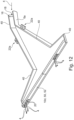
- Figure 12 shows the partial shell 6a in the pre-assembled state.
- the component 2 contains a Fig. 1 concealed air guide element 50, here in the form of an outlet part 52 or an outlet geometry.
- the air guide element 50 has the plurality of outlet openings 20 of the component 2.
- the structural part 10d is also a particle foam part that was manufactured integrally together with the partial shell 6a, i.e. is integrated in one piece into the partial shell 6a.
- an air guide element 50 which would be used, for example, as an injection-molded part (very different length expansion compared to particle foam) between partial shells 6a, b, no problems arise due to different length expansion of the air guide element 50 and partial shells 6a, b.
Landscapes
- Health & Medical Sciences (AREA)
- General Health & Medical Sciences (AREA)
- Pulmonology (AREA)
- Engineering & Computer Science (AREA)
- Aviation & Aerospace Engineering (AREA)
- Duct Arrangements (AREA)
- Air-Flow Control Members (AREA)
Description
- Die Erfindung betrifft ein Bauteil zur Luftführung für eine Klimaanlage eines Flugzeuges.
- Bisher werden Luftführungsbauteile im Flugzeug aus faserverstärkten Kunststoffen (Kohle- oder Glasfaser in Kunststoffmatrix), als Sandwichaufbau (Faserbauteile und Wabenstrukturen) oder in Hybridbauweise (Kohle- und Glasfaser in Kunststoffmatrix) hergestellt. Komplexe Bauteile (wie z.B. Luftauslässe) werden aus mehreren Einzelbauteilen hergestellt, die aufwendig miteinander gefügt werden.
- So werden für die bekannte Herstellung eines solchen Bauteils z.B. mehrere Lagen Prepreg allein oder in Verbindung mit PVDF-Schaum (Polyvinylidenfluorid) oder Wabe und/oder Folie in ein Heißpresswerkzeug eingelegt. Beide Werkzeughälften sind formgebend und die eingelegten Lagen werden unter definiertem Druck und Temperatur gepresst, die Lagen härten aus und verbinden sich miteinander.
- Es entstehen zwei Halbschalen, die in einem nachgelagerten Prozessschritt zusammen mit den notwendigen Anbau- und Einbauteilen miteinander verklebt werden.
- Aus der
DE 10 2016 121 366 A1 ist ein Verkleidungs-Paneel mit einem Paneel Element, einer rechteckigen Durchbrechung und einer Klappe bekannt. Das Verkleidungs-Paneel weist eine Klappe auf, welche drehbar um ein Gelenk ist, welches in das Paneel Element integriert ist, um die rechteckige Durchbrechung zu öffnen und/oder zu schließen. - Aus der
EP 1 299 219 B1 ist ein Verfahren zur Herstellung von Formteilen aus Partikelschaum mit einer Deckschicht bekannt. - Aus der
DE 20 2012 004 525 U1 ist ein Revisionsklappensystem zum reversiblen Verschließen einer Öffnung in einer Gehäuse-, Wand- oder Deckenverkleidung mit einem Rahmen und einer verriegelbaren Klappe bekannt. Der Rahmen und die verriegelbare Klappe ist aus Partikelschaum hergestellt und wird in ein Gehäuse-, Wand- oder Deckenelement integriert, das ebenfalls aus Partikelschaum hergestellt ist. - Aus der
US 2012/0248839 A1 ist eine Kissenstruktur bekannt, die dem Benutzer im Sitzen keine Schmerzen bereitet und die gleichmäßige Atmung fördert. - Aus der
WO 2016/004522 A1 ist ein Luftführungsbauteil für eine Klimaanlage eines Fahrzeuges bekannt, welches aus zwei Teilschalen gebildet ist, die wiederum Partikelschau-Teile sind. - Auch aus der
EP 1 959 209 A2 ist ein Luftführungsbauteil bekannt, welches ein einen Luftkanal aufweisendes Gehäuse umfasst. Das Gehäuse kann mehrteilig ausgebildet sind, wobei die einzelnen Teile aus Partikelschaum gebildet sein können. - Die
DE 10 2008 050 546 A1 offenbart ein Luftführungselement für eine Flugzeugklimaanlage, umfassend ein Verteilerrohr, das eine im Bereich einer Stirnfläche des Verteilerrohrs angeordnete Lufteinlassöffnung sowie eine im Bereich einer Mantelfläche des Verteilerrohrs angeordnete Luftableitungsöffnung aufweist. - Aus der
DE 10 2013 002 893 A1 ist ein Luftführungsbauteil für eine Klimaanlage eines Luftfahrzeuges bekannt, das aus einem Faserverbundkunststoff sowie einem Kunststoffschaum gebildet ist. - Aufgabe der vorliegenden Erfindung ist es, Verbesserungen hinsichtlich Luftführungsbauteilen vorzuschlagen.
- Die Aufgabe wird gelöst durch ein Bauteil gemäß Patentanspruch 1. Bevorzugte oder vorteilhafte Ausführungsformen der Erfindung ergeben sich aus den weiteren Ansprüchen, der nachfolgenden Beschreibung sowie den beigefügten Figuren.
- Das Bauteil dient zur Führung von Luft, also zur Luftführung. Die Luftführung findet innerhalb bzw. bei einer Klimaanlage eines Flugzeuges statt. Derartige Bauteile werden auch Luftführungs- oder Klimabauteile genannt.
- Das Bauteil weist mindestens eine Eintrittsöffnung für Luft und mindestens eine Austrittsöffnung für Luft auf. Insbesondere ist genau eine Eintrittsöffnung vorgesehen. Insbesondere ist genau eine Austrittsöffnung oder mehrere Austrittsöffnungen, z.B. auch drei, vier oder eine Vielzahl, vorgesehen. Das Bauteil enthält mindestens zwei Teilschalen, insbesondere genau zwei Teilschalen, insbesondere in Form von Halbschalen.
- Die Teilschalen sind in einem Montagezustand bzw. Fertigzustand des Bauteils luftdicht miteinander verbunden. Bei bzw. nach der Verbindung bleiben die Eintrittsöffnungen und die Austrittsöffnungen frei, so dass das Bauteil seine Funktion der internen Luftführung von den Eintrittsöffnungen zu den Austrittsöffnungen erfüllen kann.
- Die Teilschalen sind Partikelschaum-Teile, d.h. diese sind bei deren Herstellung aus Partikelschaum gefertigt.
- Das Flugzeug ist insbesondere ein Passagierflugzeug. Das Bauteil ist insbesondere für den Innenraum des Flugzeuges bestimmt bzw. in einem Einbauzustand dort montiert. Der Innenraum ist insbesondere eine Passagierkabine. Das Bauteil ist insbesondere ein Luftauslassbauteil, d.h. die Luftauslässe münden in einen freien Raum, insbesondere den Innenraum des Flugzeuges.
- Durch die Verwendung von Partikelschaum wird neben einer Gewichtseinsparung auch generell eine Verkürzung der Prozesszeiten bei der Herstellung erreicht. So werden in den o.g. bekannten bzw. etablierten Verfahren die o.g. bekannten Bauteile in einer Heißpresse hergestellt, was etwa 15 Minuten Prozesszeit erfordert. Das Partikelschäumen dagegen dauert bei einem vergleichbaren Bauteil ca. 5 Minuten.
- Die Erfindung beruht auf der Erkenntnis, dass sich durch das Aufschäumen von Materialien eine Werkstoffgruppe der Partikelschäume ergibt, welche aufgrund ihrer besonderen Struktur und damit zusammenhängenden Eigenschaften Verwendungsmöglichkeiten anderer Weise und somit neue Einsatzgebiete eröffnet.
- Durch die Wahl des richtigen Materials und des Schäumverfahrens können gewünschte Eigenschaften des Schaumstoffes erreicht werden.
- Das Herstellen von Partikelschäumen verspricht innerhalb der Gruppe der Polymerschäume ein enormes Leichtbaupotential, da ihr Hauptbestandteil mit über 90 % Luft bildet. Die Dichte eines Partikelschaums kann derzeit in einem Bereich von 8 - 200 g/l variiert werden. Hierdurch kann Einfluss auf weitere Eigenschaften wie die mechanischen Eigenschaften oder thermische Isolierfähigkeit genommen werden.
- Erfindungsgemäß enthält das Bauteil mindestens ein Strukturteil. Durch Strukturteile können variantenreiche Bauteile geschaffen werden, die durch die Teilschalen alleine nicht realisierbar wären.
- Erfindungsgemäß ist wenigstens eines der Strukturteile eine die Eintrittsöffnung bildende oder enthaltende oder an der Eintrittsöffnung angebrachte Endmuffe. Mithilfe einer derartigen Endmuffe kann das Bauteil an weitere Luftführungsbauteile angeschlossen werden.
- Erfindungsgemäß ist die Endmuffe dadurch im Bauteil befestigt, dass sie formschlüssig zwischen mindestens zwei der Teilschalen aufgenommen ist, wobei die Endmuffe beim Fügen der Teilschalen aneinander zwischen diesen formschlüssig einlegbar ist. Die entsprechenden Teilschalen bilden also zusammen mit der Endmuffe - insbesondere dank an den jeweiligen Komponenten angeformter Passungen, Vorsprüngen, Hinterschnitten, Nuten, Federn, usw. - eine Formschlussverbindung.
- Bei Luftauslässen als Bauteilen dient eine Endmuffe insbesondere als Verbindungsstück zu der angrenzenden bzw. luftzuführenden Rohrleitung. Die Endmuffe wird z.B. als Spritzgussteil hergestellt und vor dem Fügevorgang in eine Halbschale gesteckt. Durch das Fügen der beiden Halbschalen entsteht eine verliersichere Verbindung zwischen Endmuffe und Luftauslass. Ein den Formschluss (zusammen mit einem Gegenstück in den Teilschalen) bewirkender Bund an der Muffe überträgt Momente in den Luftauslass und/oder stellt gleichzeitig eine Verdrehsicherung dar.
- Insbesondere weist die Endmuffe einen Kragen auf, der in eine Nut in den Teilschalen eingreift. Insbesondere ist zwischen Bauteil und Endmuffe eine Verdrehsicherung realisiert.
- In einer bevorzugten Ausführungsform ist ein weiteres Strukturteil ein Luftleitelement, das eine Luftführung im und/oder am Bauteil bewirkt. So können gewünschte Luftführungseigenschaften im und/oder am Bauteil erreicht werden.
- In einer bevorzugten Variante dieser Ausführungsform ist das Luftleitelement ein Auslassteil, das mindestens eine, insbesondere alle, der Austrittsöffnungen bildet. So können gewünschte Auslasseigenschaften für die entsprechenden Austrittsöffnungen und damit das gesamte Bauteil dargestellt werden. Das Auslassteil ist insbesondere ein Auslassgitter. Die Gitteröffnungen bilden dabei die Austrittsöffnungen. Auslassgitter sind als Auslassteile besonders etabliert.
- In einer bevorzugten Ausführungsform ist das Strukturteil ein Partikelschaum-Teil. Die Partikelschaum-Technik wird somit nicht nur für die Teilschalen, sondern auch für die Strukturteile genutzt, weshalb die entsprechenden Vorteile auch für Strukturteile gelten.
- In einer bevorzugten Variante dieser Ausführungsform ist das Strukturteil einstückig in eine der Teilschalen integriert. Dies ermöglicht, Strukturteil und Teilschale als integriertes einziges Bauteil gemeinsam zu fertigen. Außerdem kann so die Endmontage des gesamten Bauteils erleichtert werden, da weniger Einzelteile zu handhaben sind.
- In einer bevorzugten Ausführungsform ist ein weiteres Strukturteil ein in den Partikelschaum einer Teilschale eingeschäumtes Strukturteil, das kein Partikelschaum-Teil ist. Somit besteht die Möglichkeit, auch Strukturteile einzubeziehen, die insbesondere nicht oder nur schwer oder unzureichend als Partikelschaum-Teile realisierbar wären. Dies trifft insbesondere für metallische Strukturteile und/oder Halterungselemente als Strukturteile zu.
- In einer bevorzugten Variante dieser Ausführungsform ist das Strukturteil eine Buchse oder eine Langlochbuchse. Die Langlochbuchse enthält insbesondere eine entlang des Langlochs gleitbare Gleitbuchse. Eine entsprechende Buchse dient als Festlager, eine entsprechende Langlochbuchse mit Gleitbuchse als Loslager für das Bauteil. Insbesondere mit Hilfe des Loslagers können Dimensionsänderungen durch thermische Ausdehnung zwischen Bauteil und Untergrund, auf welchem das Bauteil befestigt ist, ausgeglichen werden. Hierbei ist zu bedenken, dass insbesondere im Luftfahrtbereich Temperaturspannen von -55°C bis +88°C zu berücksichtigen sind.
- In einer bevorzugten Ausführungsform weisen mindestens zwei der Teilschalen zur Verbindung miteinander eine lösbare Steckverbindung auf. Die Steckverbindung ist insbesondere am Rand der Teilschalen platziert. Wie die Teilschalen selbst ist auch die entsprechende Verbindung aus Partikelschaum gefertigt. Insbesondere ist die Verbindung eine Nut- und Feder-Verbindung. Die Steckverbindung bzw. deren Komponenten ist somit einstückiger Teil der jeweiligen Teilschalen und ist somit besonders einfach und günstig herzustellen. Bei der Endmontage werden so keine zusätzlichen Verbindungs- /Dichtungsteile benötigt, um die beiden Teilschalen miteinander zu verbinden und/oder abzudichten. Insbesondere wird die Steckverbindung mit leichtem Übermaß dimensioniert und die elastischen Eigenschaften des Partikelschaums genutzt, um eine Steckverbindung zu realisieren, die eine gewisse Haltekraft aufweist.
- In einer bevorzugten Variante dieser Ausführungsform ist die Steckverbindung eine Schnappverbindung (z.B. "snap and click") mit einem im Steckzustand hintergriffenen Hinterschnitt. Insbesondere weist die Nut den Hinterschnitt auf, der von einem Vorsprung der Feder hintergriffen ist. Auch hier werden die elastischen Eigenschaften des Partikelschaums genutzt, um eine für die Schnappverbindung notwendige Flexibilität zu erzielen. Eine entsprechende Schnappverbindung weist eine erhöhte Haltekraft gegenüber einer Nut- und Federverbindung ohne Hinterschnitt auf.
- In einer bevorzugten Ausführungsform enthält das Bauteil ein Sicherungselement, das wenigstens zwei der Teilschalen aneinander fixiert. Ein derartiges Sicherungselement ist beispielsweise eine Klammer-, eine Schraubverbindung, eine in den Partikelschaum schneidende Schraube usw. insbesondere wird das Sicherungselement alternativ oder zusätzlich zur oben genannten Steck-/Schnappverbindung realisiert.
- In einer bevorzugten Ausführungsform ist der Partikelschaum expandierendes Polypropylen (EPP). Dieses Material ist für den entsprechenden Einsatz besonders geeignet.
- Die Erfindung beruht auf folgenden Erkenntnissen, Beobachtungen bzw. Überlegungen und weist noch die nachfolgenden Ausführungsformen auf.
- Die Erfindung beruht auf der Überlegung, Luftführungsbauteile für Klimaanlagen in Flugzeugen in Partikelschaum zu entwickeln, die den Anforderungen der Luftfahrt entsprechen. Die Überlegung besteht weiter darin, möglichst viele Funktionen des Bauteils in den Herstellprozess zu integrieren, um eine schnelle und kostengünstige Herstellung zu erreichen. Außerdem sollen die aufgrund des breiten Temperatureinsatzbereiches des Flugzeuges stark unterschiedlichen thermischen Eigenschaften zwischen Partikelschaum und faserverstärkten Kunststoffen, die zu Eigenspannungen im Schaumbauteil und zu Rissen in dessen Struktur führen können, betrachtet und geeignete Maßnahmen zur Kompensation der thermischen Effekte entwickelt werden.
- Gemäß einer Ausführungsform der Erfindung bestehen die Bauteile aus zwei separat geschäumten Halbschalen aus Expandierendem Polypropylen (EPP). Im Herstellprozess der Halbschalen werden separat hergestellte Bauteile (Strukturteile, (Langloch-)Buchsen), die als Halterungselemente fungieren, mit eingeschäumt. Diese Bauteile dienen als hartes Auflager, definierte Führung des Befestigungselements und Ausreißschutz des Partikelschaums und werden während des Schäumprozesses der Halbschale positionsgenau, formschlüssig und verliersicher umschäumt.
- Durch geeignete konstruktive Gestaltung (insbesondere der Wandstärken / Berücksichtigung der möglichen Entformung der Bauteile) der innenliegenden Funktionselemente zur Luftführung (Luftleitelement) können diese im selben Prozessschritt zusammen mit den Halbschalen geschäumt werden. Es ist möglich, die Elemente in einer Halbschale komplett oder nur in jeder Halbschale nur einen Teil davon abzubilden und diese im späteren Fügeprozess miteinander zu verbinden. Die oben beschriebenen eingeschäumten Halterungselemente werden an entsprechenden Positionen mit translatorischem Freiheitsgrad für ein darin montiertes weiteres Gleitlager (Gleitbuchse) ausgeführt. Diese Gleitlager können sich darin bewegen und generieren entsprechend ein Loslager mit translatorischem Freiheitsgrad, wodurch die unterschiedlichen thermischen Längenausdehnungen der Materialien kompensiert werden können.
- Die Fügenaht wird bei den beiden Halbschalen als Nut-Feder-Verbindung ausgeführt, sodass eine zunächst lösbare Steckverbindung entsteht. Durch geeignete Gestaltung von Nut und Feder wird schon allein durch das Ineinanderstecken eine stabile Verbindung inklusive Luftdichtigkeit erreicht. Dabei werden die Eigenschaften des Schaumes hinsichtlich Verformbarkeit und Rückstellverhalten ausgenutzt. Über zusätzliche Sicherungselemente können die beiden Halbschalen zusätzlich fixiert werden.
- Damit auch für die Einbringung einer Endmuffe als Verbindungsstück zu der angrenzenden Rohrleitung kein nachgelagerter aufwendiger Prozessschritt (wie z.B. Kleben) notwendig ist, wird in den Partikelschaum-Halbschalen eine Nut vorgesehen. Die Endmuffe besitzt einen der Nut entsprechenden Steg (Kragen) und wird während des Fügeprozesses der beiden Halbschalen in die Nut gesteckt und durch das Fügen der Halbschalen entsteht eine verliersichere Verbindung.
- Die Ausnutzung des Materialverhaltens für die Fügeverbindung der Halbschalen wird durch geeignete Gestaltung der Nut und Feder erreicht. Es ergibt sich ein hochintegrativer Herstellprozess durch Integration weiterer Funktionsbauteile in den Schäumprozess unter Berücksichtigung des thermischen Materialverhaltens. So wird beispielsweise ein vergleichsweise langes Spritzgussteil durch ein Partikelschaum-Teil ersetzt: während das Spritzgussteil im Partikelschaum Probleme zwecks stark unterschiedlicher Längenausdehnungen verursachen würde, gibt es bei "Partikelschaum in Partikelschaum" derartige Probleme nicht. Gemäß entsprechender Überlegungen können auch an geeigneten Stellen des Bauteils Festlager oder Loslager (insbesondere zum thermischen Längenausgleich) vorgesehen werden. Es ergibt sich die Abbildung der Luftführungsgeometrien in Partikelschaum und der daraus resultierenden Gewichtseinsparung, sowie die Einsparung von zusätzlichen Prozessschritten.
- Insbesondere werden während des Herstellprozesses einer Luftauslass-Halbschale in Partikelschaum separat hergestellte Bauteile (Buchsen) in die Werkzeugkavität eingelegt und während des Schäumens des eigentlichen Bauteils umschäumt. Es entsteht eine formschlüssige, verliersichere Verbindung zwischen geschäumter Halbschale und eingelegtem Bauteil. Die Buchsen dienen als hartes Auflager, definierte Führung des Befestigungselements (Lochleibung) und Ausreißschutz des Partikelschaums, über die der Luftauslass gehaltert werden kann.
- Durch die neue Technologie der Luftführungsbauteile in Partikelschaum entsteht beim Zusammenbau der Luftauslässe mit den Komponenten (Hatrack, Sekundärstruktur, Primärstruktur), auf die montiert wird, eine Verbindung von Materialien mit sehr unterschiedlichen thermischen Längenausdehnungskoeffizienten. Dies führt bei den Schaumbauteilen zu einer um bis zu Faktor fünf und mehr erhöhten Längenausdehnung. Diese Unterschiede generieren Eigenspannungen im Schaumbauteil und können zu Rissen in dessen Struktur führen.
- Zur Kompensation werden Langlochbuchsen im Herstellungsprozess der Luftauslasshalbschalen integriert. Diese Langlochbuchsen haben eine der Längenausdehnung angepasste Größe. In diese Langlochbuchsen werden Gleitbuchsen montiert und generieren somit ein Loslager mit translatorischem Freiheitsgrad. Die Befestigung des Luftauslasses erfolgt dann z.B. über Schrauben durch die Gleitbuchsen.
- Durch die Integration der einzelnen Funktionen und die Ausführung der Fügeverbindung als Steckverbindung entsteht ein kostenoptimierter hochintegrativer Herstellprozess.
- Gemäß der Erfindung ergibt sich die Herstellung eines Luftauslasses in Partikelschaum, bestehend aus zwei Halbschalen. In die Schalen integriert sind zusätzliche Bauteile zur Halterung und gleichzeitigen Kompensation thermischer Ausdehnungseffekte, sowie die Abbildung verschiedener Luftführungsgeometrien in Partikelschaum. Die Schalen werden über eine Nut-Feder-Verbindung ineinander gesteckt und über zusätzliche Sicherungselemente gesichert.
- Gemäß der Erfindung ergeben sich Luftführungsbauteile in Partikelschaumbauweise (EPP) für das Klimasystem in Flugzeugen.
- Die Erfindung bietet die Vorteile einer Gewichtsreduktion, Kostenreduktion, Verbesserung der Prozesszeiten, eine integrative Herstellweise und die Anwendung einer neuen Technologie.
- Anwendung findet die Erfindung beispielsweise für einen Deckenluftauslass Single Aisle oder einen seitlichen Luftauslass Single Aisle.
- Weitere Merkmale, Wirkungen und Vorteile der Erfindung ergeben sich aus der nachfolgenden Beschreibung eines bevorzugten Ausführungsbeispiels der Erfindung sowie der beigefügten Figuren. Dabei zeigen, jeweils in einer schematischen Prinzipskizze:
- Figur 1
- ein Luftführungsbauteil in einer Vormontagestellung mit Endmuffe,
- Figur 2
- das Detail II aus
Fig. 1 im Montagezustand, - Figur 3
- das Luftführungsbauteil aus
Fig. 1 im Montagezustand ohne Endmuffe, - Figur 4
- das Detail IV aus
Fig. 3 , - Figur 5
- den Querschnitt A-A durch
Fig. 4 , - Figur 6
- die Anordnung aus
Fig. 4 bei Befestigung an einem Untergrund, - Figur 7
- das Detail VII aus
Fig. 3 , - Figur 8
- den Querschnitt A-A durch
Figur 7 , - Figur 9
- die Anordnung aus
Fig. 7 bei Befestigung an einem Untergrund, - Figur 10
- das Detail X aus
Fig. 3 im Querschnitt, - Figur 11
- ein Sicherungselement im Bauteil im Bereich des Details X bei alternativem Querschnitt,
- Figur 12
- eine Halbschale des Bauteils aus
Fig. 1 ohne Endmuffe aber mit Luftleitelement. -
Figur 1 zeigt ein Bauteil 2 zur Führung von Luft 4 (im Betrieb), angedeutet durch einen Pfeil. Das Bauteil 2 ist ein Bauteil für eine nicht weiter dargestellte Klimaanlage eines Flugzeuges. Das Bauteil 2 enthält zwei Teilschalen 6a,b, hier in Form von Halbschalen. Die Teilschalen 6a,b sind Partikelschaum-Teile, d.h. aus Partikelschaum gefertigt bzw. hergestellt.Figur 1 zeigt eine Vormontagestellung, d.h. die beiden Teilschalen 6a,b sind noch nicht aneinandergefügt. Zum Zusammenbau werden die Teile in Richtung der Pfeile 8 aufeinander zu bewegt und (an ihren Rändern unter Auslassung von Ein- und Austrittsöffnungen für Luft 4, siehe unten) luftdicht miteinander zum Bauteil 2 verbunden. - Das Bauteil 2 enthält ein Strukturteil 10a, hier eine Endmuffe 12. Die Endmuffe 12 dient als Verbindungstück des Bauteils 2 zu einer angrenzenden, nicht dargestellten Rohrleitung. Im Montagezustand M und Betrieb wird die Luft 4 durch die Endmuffe 12 in das Bauteil 2 geleitet. Vor dem Fügevorgang der beiden Teilschalen 6a,b wird die Endmuffe 12 in die Teilschale 6a oder 6b gesteckt. Hierzu weist die Endmuffe 12 einen Bund 14 auf. Die Teilschalen 6a,b weisen eine entsprechende Nut 16 zur Aufnahme des Bundes 14 auf. Durch das Fügen der beiden Teilschalen 6a,b aneinander in Richtung der Pfeile 8 wird die Endmuffe 12 formschlüssig und verliersicher im restlichen Bauteil 2 aufgenommen.
-
Figur 2 zeigt das Detail II ausFigur 1 nach dem Fügevorgang im Querschnitt entlang der Ebene A-A und damit den Montagezustand M des Bauteils 2. Das Bauteil 2 weist nun eine Eintrittsöffnung 18 für die Luft 4 auf. Vorliegend weist auch die Endmuffe 12 die Eintrittsöffnung 18 auf bzw. liegt die Endmuffe 12 in der Eintrittsöffnung 18. -
Figur 3 zeigt das gesamte Bauteil 2 im Montagezustand M, allerdings unter Weglassung der Endmuffe 12. Das Bauteil 2 weist eine Vielzahl von Austrittsöffnungen 20 für die Luft 4 auf, die weiter unten näher erläutert werden. - Das Bauteil 2 weist außerdem insgesamt vier Haltepunkte 22a,b auf. Die Haltepunkte 22a,b befinden sich jeweils an nicht näher bezeichneten Fortsätzen bzw. Anformungen des Bauteils 2. Zwei Haltepunkte 22a sind als Festlager, zwei Haltepunkte 22b als Loslager ausgebildet.
-
Figur 4 zeigt einen der Haltepunkte 22a im Detail IV ausFigur 3 . Der Haltepunkt 22a ist dadurch gebildet, dass der Fortsatz bei der Herstellung der Teilschalen 6a und/oder 6b einstückig aus Partikelschaum mit gefertigt wurde und in den Partikelschaum ein weiteres Strukturteil 10b, hier eine Buchse 24, eingeschäumt wurde. -
Figur 5 zeigt den Querschnitt entlang der Ebene A-A durchFigur 4 . Hier ist zu erkennen, wie die Buchse 24 durch Einschäumen formschlüssig fest in der Teilschale 6a,b bzw. deren Fortsatz gehalten ist. -
Figur 6 zeigt, wie das Bauteil 2 mithilfe einer Schraube 26, die durch die Buchse 24 geführt ist, und untergelegter Scheibe 27an einem nicht dargestellten Untergrund verschraubt ist. Aufgrund des vergleichsweise geringen Abstandes d1 von ca. 10cm zwischen den beiden Haltepunkten 22a treten hier kaum Längenänderungen des Bauteils 2 bei Temperaturveränderungen auf, so dass hier feste Buchsen 24 zur Verschraubung ausreichen, ohne nennenswerte Verspannungen im Bauteil 2 hervorzurufen. -
Figur 7 zeigt das Detail VII ausFigur 3 und damit einen der Haltepunkte 22b. Sinngemäß gleich zur Buchse 24, wie oben beschrieben, ist hier jedoch als Strukturteil 10c eine Langlochbuchse 28 in einem angeformten einstückigen Fortsatz der Teilschale 6a,b formschlüssig eingeschäumt. Innerhalb der Langlochbuchse 28 ist eine zweiteilige (um diese montieren zu können) Gleitbuchse 30 verschiebbar gelagert, sodass ein Loslager entsteht. -
Figur 8 zeigt den Querschnitt entlang der Ebene A-A durchFigur 7 . Hier ist zu erkennen, wie die Langlochbuchse 28 durch Einschäumen fest in der Teilschale 6a,b bzw. deren Fortsatz gehalten ist und wie die zweiteilige Gleitbuchse 30 in der Langlochbuchse 28 linear verschiebbar geführt ist. -
Figur 9 zeigt entsprechendFigur 6 , wie das Bauteil 2 mithilfe einer Schraube 26, die durch die Gleitbuchse 30 geführt ist, und Scheibe 27an einem nicht dargestellten Untergrund linear beweglich verschraubt ist. Aufgrund des vergleichsweise großen Abstandes d2 von ca. 100cm zwischen den beiden Haltepunkten 22a treten hier merkliche Längenänderungen des Bauteils 2 bei Temperaturveränderungen auf, so dass hier Loslager mit verschiebbaren Gleitbuchsen 30 zur Verschraubung gewählt sind, um nennenswerte Verspannungen im Bauteil 2 zu vermeiden. -
Figur 10 zeigt das Detail X ausFigur 3 . An den jeweiligen Randabschnitten (ausgenommen sind nur die Eintrittsöffnung 18 und die Austrittsöffnungen 20 bzw. der Bereich des Luftleitelements 50, siehe unten), an welchen die Teilschalen 6a,b luftdicht miteinander zu verbinden sind, weist die Teilschale 6a eine Feder 40 und die Teilschale 6b eine entsprechende Nut 42 auf. So ist eine Steckverbindung 43 gebildet. Die Feder 40 ist hierbei leicht kreisförmig konvex, die Nut 42 entsprechend konkav ausgestaltet, so dass diese einen Hinterschnitt 44 bildet, der von der Feder 40 im Montagezustand M bzw. Steckzustand der Steckverbindung 43 hintergriffen wird. Die Steckverbindung 43 ist damit als Schnappverbindung 45 ausgeführt. - Die Schnappverbindung 45 ist ausreichend haltbar, um während der Endmontage des Bauteils 2 die Teilschalen 6a, b aneinander zu halten.
-
Figur 11 zeigt, wie zur endgültigen Sicherung der Teilschalen 6a, b aneinander das Bauteil 2 noch mehrere Sicherungselemente 46 enthält, hier in Form von selbstschneidenden Schrauben, die im Partikelschaum verschraubt sind. Der Übersichtlichkeit halber sind die Sicherungselemente 46 in den restlichen Figuren nicht dargestellt. -
Figur 12 zeigt nochmals die Teilschale 6a im Vormontagezustand. Als weiteres Strukturteil 10d enthält das Bauteil 2 ein inFig. 1 verdecktes Luftleitelement 50, hier in Form eines Auslassteils 52 bzw. einer Auslassgeometrie. Das Luftleitelement 50 weist die Vielzahl von Austrittsöffnungen 20 des Bauteils 2 auf. Das Strukturteil 10d ist ebenfalls ein Partikelschaum-Teil, das integral zusammen mit der Teilschale 6a gefertigt wurde, also einstückig in die Teilschale 6a integriert ist. Im Gegensatz zu einem Luftleitelement 50, welches zum Beispiel als Spritzgussteil (stark unterschiedliche Längenausdehnung im Vergleich zu Partikelschaum) zwischen Teilschalen 6a, b eingesetzt würde, treten so keine Probleme wegen unterschiedlicher Längenausdehnung von Luftleitelement 50 und Teilschalen 6a,b auf. -
- 2
- Bauteil
- 4
- Luft
- 6a, b
- Teilschale
- 8
- Pfeil
- 10a-d
- Strukturteil
- 12
- Endmuffe
- 14
- Bund
- 16
- Nut
- 18
- Eintrittsöffnung
- 20
- Austrittsöffnung
- 22a, b
- Haltepunkt
- 24
- Buchse
- 26
- Schraube
- 27
- Scheibe
- 28
- Langlochbuchse
- 30
- Gleitbuchse
- 40
- Feder
- 42
- Nut
- 43
- Steckverbindung
- 44
- Hinterschnitt
- 45
- Schnappverbindung
- 46
- Sicherungselement
- 50
- Luftleitelement
- 52
- Auslassteil
- M
- Montagezustand
Claims (12)
- Bauteil (2) zur Luftführung für eine Klimaanlage eines Flugzeuges,- mit mindestens einer Eintrittsöffnung (18) und mindestens einer Austrittsöffnung (20) für Luft (4),- mit mindestens zwei Teilschalen (6a, b),- wobei die Teilschalen (6a, b) derart luftdicht miteinander verbunden sind, dass die Eintrittsöffnungen (18) und die Austrittsöffnungen (20) frei bleiben,- wobei die Teilschalen (6a, b) Partikelschaum-Teile sind,- wobei das Bauteil (2) mindestens ein Strukturteil (10a-d) enthält,wobei wenigstens eines der Strukturteile (10a-d) eine die Eintrittsöffnung (18) aufweisende Endmuffe (12) ist,dadurch gekennzeichnet, dassdie Endmuffe (12) dadurch im Bauteil (2) befestigt ist, dass sie formschlüssig zwischen mindestens zwei der Teilschalen (6a,b) aufgenommen ist, wobei die Endmuffe (12) beim Fügen der Teilschalen (6a,b) aneinander zwischen diesen formschlüssig einlegbar ist.
- Bauteil (2) nach Anspruch 1,
dadurch gekennzeichnet, dass
wenigstens eines der Strukturteile (10a-d) ein eine Luftführung im Bauteil bewirkendes Luftleitelement (50) ist. - Bauteil (2) nach Anspruch 2,
dadurch gekennzeichnet, dass
das Luftleitelement (50) ein mindestens eine der Austrittsöffnungen (20) bildendes Auslassteil (52) ist. - Bauteil (2) nach Anspruch 3,
dadurch gekennzeichnet, dass
das Luftleitelement (50) eine Vielzahl von Austrittsöffnungen (20) aufweist. - Bauteil (2) nach einem der vorhergehenden Ansprüche,
dadurch gekennzeichnet, dass
wenigstens eines der Strukturteile (10a-d) ein Partikelschaum-Teil ist. - Bauteil (2) nach Anspruch 5,
dadurch gekennzeichnet, dass
wenigstens eines der Strukturteile (10a-d) einstückig in eine der Teilschalen (6a, b) integriert ist. - Bauteil (2) nach einem der vorhergehenden Ansprüche,
dadurch gekennzeichnet, dass
wenigstens eines der Strukturteile (10a-d) ein in den Partikelschaum einer Teilschale (6a,b) eingeschäumtes Strukturteil (10a-d) ist, das kein Partikelschaum-Teil ist. - Bauteil (2) nach Anspruch 7,
dadurch gekennzeichnet, dass
das Strukturteil (10a-d) eine Buchse (24) oder eine Langlochbuchse (28) ist. - Bauteil (2) nach einem der vorhergehenden Ansprüche,
dadurch gekennzeichnet, dass
mindestens zwei der Teilschalen (6a,b) zur Verbindung miteinander eine lösbare Steckverbindung (43) aufweisen. - Bauteil (2) nach Anspruch 9,
dadurch gekennzeichnet, dass
die Steckverbindung (43) eine Schnappverbindung (45) mit einem im Steckzustand hintergriffenen Hinterschnitt (44) ist. - Bauteil (2) nach einem der vorhergehenden Ansprüche,
dadurch gekennzeichnet, dass
das Bauteil (2) ein Sicherungselement (46) enthält, das wenigstens zwei der Teilschalen (6a,b) aneinander fixiert. - Bauteil (2) nach einem der vorhergehenden Ansprüche,
dadurch gekennzeichnet, dass
der Partikelschaum expandierendes Polypropylen ist.
Applications Claiming Priority (3)
| Application Number | Priority Date | Filing Date | Title |
|---|---|---|---|
| DE102018007505.3A DE102018007505A1 (de) | 2018-09-24 | 2018-09-24 | Luftführungsbauteil und Herstellungsverfahren |
| EP19779786.3A EP3856638B1 (de) | 2018-09-24 | 2019-09-24 | Luftführungsbauteil und herstellungsverfahren |
| PCT/EP2019/075592 WO2020064665A1 (de) | 2018-09-24 | 2019-09-24 | Luftführungsbauteil und herstellungsverfahren |
Related Parent Applications (2)
| Application Number | Title | Priority Date | Filing Date |
|---|---|---|---|
| EP19779786.3A Division-Into EP3856638B1 (de) | 2018-09-24 | 2019-09-24 | Luftführungsbauteil und herstellungsverfahren |
| EP19779786.3A Division EP3856638B1 (de) | 2018-09-24 | 2019-09-24 | Luftführungsbauteil und herstellungsverfahren |
Publications (3)
| Publication Number | Publication Date |
|---|---|
| EP4328135A2 EP4328135A2 (de) | 2024-02-28 |
| EP4328135A3 EP4328135A3 (de) | 2024-05-15 |
| EP4328135B1 true EP4328135B1 (de) | 2024-12-25 |
Family
ID=68104577
Family Applications (2)
| Application Number | Title | Priority Date | Filing Date |
|---|---|---|---|
| EP19779786.3A Active EP3856638B1 (de) | 2018-09-24 | 2019-09-24 | Luftführungsbauteil und herstellungsverfahren |
| EP24151828.1A Active EP4328135B1 (de) | 2018-09-24 | 2019-09-24 | Luftführungsbauteil |
Family Applications Before (1)
| Application Number | Title | Priority Date | Filing Date |
|---|---|---|---|
| EP19779786.3A Active EP3856638B1 (de) | 2018-09-24 | 2019-09-24 | Luftführungsbauteil und herstellungsverfahren |
Country Status (4)
| Country | Link |
|---|---|
| US (1) | US12208905B2 (de) |
| EP (2) | EP3856638B1 (de) |
| DE (1) | DE102018007505A1 (de) |
| WO (1) | WO2020064665A1 (de) |
Families Citing this family (1)
| Publication number | Priority date | Publication date | Assignee | Title |
|---|---|---|---|---|
| DE102022000756A1 (de) | 2022-03-03 | 2023-09-07 | Truma Gerätetechnik GmbH & Co. KG | Klimagerät |
Family Cites Families (10)
| Publication number | Priority date | Publication date | Assignee | Title |
|---|---|---|---|---|
| DE10033877A1 (de) * | 2000-07-12 | 2002-03-14 | Fraunhofer Ges Forschung | Verfahren zur Herstellung von Formteilen aus Partikelschaum mit einer Deckschicht |
| US6752712B1 (en) * | 2003-02-10 | 2004-06-22 | The Boeing, Company | Slotted air distribution nozzle restrictor assembly |
| EP1959209A3 (de) * | 2007-02-19 | 2009-12-30 | MAICO ELEKTROAPPARATE-FABRIK GmbH | Steuer- und/oder Regeleinheit zur Dosierung eines Luftstroms, Lüftungssystem |
| DE102008050546B4 (de) * | 2008-10-06 | 2012-03-08 | Airbus Operations Gmbh | Side-Feeder-Luftführungselement für eine Flugzeugklimaanlage |
| JP2011078503A (ja) * | 2009-10-05 | 2011-04-21 | Delta Tooling Co Ltd | クッション構造及び乗物用シート |
| DE202012004525U1 (de) * | 2012-05-09 | 2012-07-30 | Ruch Novaplast Gmbh + Co. Kg | Revisionsklappensystem |
| DE102013002893A1 (de) | 2013-02-20 | 2014-08-21 | Diehl Aircabin Gmbh | Hybridbauteil und Herstellungsverfahren |
| CA2916612A1 (en) * | 2014-07-11 | 2016-01-11 | Exo-S Inc. | A light-weight air duct for ventilation, air conditioning and heating for use in a vehicle and a method of manufacturing same |
| DE102016121366B4 (de) | 2016-11-08 | 2021-08-12 | Airbus Operations Gmbh | Verkleidungs-paneel und verfahren zum herstellen eines verkleidungs-paneels |
| WO2019038213A1 (de) | 2017-08-24 | 2019-02-28 | Evonik Röhm Gmbh | Pei-partikelschäume für anwendungen im luftfahrt-interieur |
-
2018
- 2018-09-24 DE DE102018007505.3A patent/DE102018007505A1/de not_active Withdrawn
-
2019
- 2019-09-24 EP EP19779786.3A patent/EP3856638B1/de active Active
- 2019-09-24 WO PCT/EP2019/075592 patent/WO2020064665A1/de not_active Ceased
- 2019-09-24 EP EP24151828.1A patent/EP4328135B1/de active Active
-
2021
- 2021-03-19 US US17/206,500 patent/US12208905B2/en active Active
Also Published As
| Publication number | Publication date |
|---|---|
| US20210206496A1 (en) | 2021-07-08 |
| EP3856638B1 (de) | 2024-03-13 |
| US12208905B2 (en) | 2025-01-28 |
| DE102018007505A1 (de) | 2020-03-26 |
| WO2020064665A1 (de) | 2020-04-02 |
| EP3856638A1 (de) | 2021-08-04 |
| EP4328135A2 (de) | 2024-02-28 |
| EP4328135A3 (de) | 2024-05-15 |
Similar Documents
| Publication | Publication Date | Title |
|---|---|---|
| DE102012216039B4 (de) | Gehäuse für eine Klimaanlage | |
| DE102007024804A1 (de) | Selbsttragendes Karosserie-Struktur-Verbundbauteil-Modul | |
| WO2012003964A1 (de) | Interieurkomponententrägersystem, flugzeuginterieurkomponentenmodul und montageverfahren | |
| DE102007019539A1 (de) | Luftzufuhrvorrichtung für die Klimatisierung von Passagierräumen in Flugzeugen | |
| EP0553640A2 (de) | Luftkanalanordnung für die Lüftung oder Klimatisierung eines Fahrzeuginnenraumes sowie Verfahren zur Herstellung einer Luftkanalanordnung | |
| DE102006028956A1 (de) | Flugzeugseitenverkleidung | |
| DE102013005523A1 (de) | Gehäuse | |
| DE102016121366A1 (de) | Verkleidungs-paneel und verfahren zum herstellen eines verkleidungs-paneels | |
| EP4328135B1 (de) | Luftführungsbauteil | |
| EP1362744B1 (de) | Bauelement aus Kunststoff, insbesondere für ein Kraftfahrzeug, und Verfahren zu seiner Herstellung | |
| DE102008025959A1 (de) | Vorrichtung zur Verbindung von zwei Rohrleitungselementen und einer Blende in einer Flugzeugklimatisierungsanlage | |
| EP3233546B1 (de) | Verfahren zur herstellung eines karosseriebauteils für ein kraftfahrzeug, vorrichtung zur herstellung eines karosseriebauteils für ein kraftfahrzeug und karosseriebauteil für ein kraftfahrzeug | |
| DE102017117274A1 (de) | Gepäckfach zur rumpf- oder deckenseitigen Installation in einem Fahrzeug und Verfahren zum Herstellen eines derartigen Gepäckfachs | |
| DE102007008987A1 (de) | Rumpf eines Luft-oder Raumfahrzeugs sowie ein Verfahren zum aktiven Isolieren eines solchen Rumpfes | |
| DE102009017758A1 (de) | Dachhimmelelement für ein Kraftfahrzeug | |
| DE202015001340U1 (de) | Karosserie-Leichtbauelement | |
| DE102007061253A1 (de) | Flugzeugrumpfelement | |
| DE202007012988U1 (de) | Mehrkanalige Luftführungsvorrichtung | |
| EP3883797A1 (de) | Dachhimmelverkleidung sowie verfahren zur herstellung einer dachhimmelverkleidung | |
| DE19936770A1 (de) | Fußbodenverkleidung für den Fahrgastraum von Kraftfahrzeugen | |
| DE102012223864B3 (de) | Vorrichtung zur Aufnahme mindestens einer Komponente eines SOFC-Brennstoffzellensystems und Verfahren zur Herstellung einer solchen Vorrichtung | |
| EP1418071B1 (de) | Luftleitvorrichtung | |
| DE102016007157A1 (de) | Führungsrohr und Herstellungsverfahren | |
| DE602004012790T2 (de) | Armaturenbrett für Kraftfahrzeug | |
| EP3762660A1 (de) | Kanalbauteil für luftverteilungssysteme |
Legal Events
| Date | Code | Title | Description |
|---|---|---|---|
| PUAI | Public reference made under article 153(3) epc to a published international application that has entered the european phase |
Free format text: ORIGINAL CODE: 0009012 |
|
| STAA | Information on the status of an ep patent application or granted ep patent |
Free format text: STATUS: THE APPLICATION HAS BEEN PUBLISHED |
|
| AC | Divisional application: reference to earlier application |
Ref document number: 3856638 Country of ref document: EP Kind code of ref document: P |
|
| AK | Designated contracting states |
Kind code of ref document: A2 Designated state(s): AL AT BE BG CH CY CZ DE DK EE ES FI FR GB GR HR HU IE IS IT LI LT LU LV MC MK MT NL NO PL PT RO RS SE SI SK SM TR |
|
| PUAL | Search report despatched |
Free format text: ORIGINAL CODE: 0009013 |
|
| STAA | Information on the status of an ep patent application or granted ep patent |
Free format text: STATUS: REQUEST FOR EXAMINATION WAS MADE |
|
| AK | Designated contracting states |
Kind code of ref document: A3 Designated state(s): AL AT BE BG CH CY CZ DE DK EE ES FI FR GB GR HR HU IE IS IT LI LT LU LV MC MK MT NL NO PL PT RO RS SE SI SK SM TR |
|
| RIC1 | Information provided on ipc code assigned before grant |
Ipc: B64D 13/00 20060101AFI20240410BHEP |
|
| 17P | Request for examination filed |
Effective date: 20240429 |
|
| RBV | Designated contracting states (corrected) |
Designated state(s): AL AT BE BG CH CY CZ DE DK EE ES FI FR GB GR HR HU IE IS IT LI LT LU LV MC MK MT NL NO PL PT RO RS SE SI SK SM TR |
|
| GRAP | Despatch of communication of intention to grant a patent |
Free format text: ORIGINAL CODE: EPIDOSNIGR1 |
|
| STAA | Information on the status of an ep patent application or granted ep patent |
Free format text: STATUS: GRANT OF PATENT IS INTENDED |
|
| INTG | Intention to grant announced |
Effective date: 20241001 |
|
| GRAS | Grant fee paid |
Free format text: ORIGINAL CODE: EPIDOSNIGR3 |
|
| GRAA | (expected) grant |
Free format text: ORIGINAL CODE: 0009210 |
|
| STAA | Information on the status of an ep patent application or granted ep patent |
Free format text: STATUS: THE PATENT HAS BEEN GRANTED |
|
| AC | Divisional application: reference to earlier application |
Ref document number: 3856638 Country of ref document: EP Kind code of ref document: P |
|
| AK | Designated contracting states |
Kind code of ref document: B1 Designated state(s): AL AT BE BG CH CY CZ DE DK EE ES FI FR GB GR HR HU IE IS IT LI LT LU LV MC MK MT NL NO PL PT RO RS SE SI SK SM TR |
|
| REG | Reference to a national code |
Ref country code: GB Ref legal event code: FG4D Free format text: NOT ENGLISH |
|
| REG | Reference to a national code |
Ref country code: CH Ref legal event code: EP |
|
| REG | Reference to a national code |
Ref country code: DE Ref legal event code: R096 Ref document number: 502019012712 Country of ref document: DE |
|
| REG | Reference to a national code |
Ref country code: IE Ref legal event code: FG4D Free format text: LANGUAGE OF EP DOCUMENT: GERMAN |
|
| REG | Reference to a national code |
Ref country code: LT Ref legal event code: MG9D |
|
| PG25 | Lapsed in a contracting state [announced via postgrant information from national office to epo] |
Ref country code: HR Free format text: LAPSE BECAUSE OF FAILURE TO SUBMIT A TRANSLATION OF THE DESCRIPTION OR TO PAY THE FEE WITHIN THE PRESCRIBED TIME-LIMIT Effective date: 20241225 |
|
| PG25 | Lapsed in a contracting state [announced via postgrant information from national office to epo] |
Ref country code: FI Free format text: LAPSE BECAUSE OF FAILURE TO SUBMIT A TRANSLATION OF THE DESCRIPTION OR TO PAY THE FEE WITHIN THE PRESCRIBED TIME-LIMIT Effective date: 20241225 |
|
| PG25 | Lapsed in a contracting state [announced via postgrant information from national office to epo] |
Ref country code: BG Free format text: LAPSE BECAUSE OF FAILURE TO SUBMIT A TRANSLATION OF THE DESCRIPTION OR TO PAY THE FEE WITHIN THE PRESCRIBED TIME-LIMIT Effective date: 20241225 |
|
| PG25 | Lapsed in a contracting state [announced via postgrant information from national office to epo] |
Ref country code: NO Free format text: LAPSE BECAUSE OF FAILURE TO SUBMIT A TRANSLATION OF THE DESCRIPTION OR TO PAY THE FEE WITHIN THE PRESCRIBED TIME-LIMIT Effective date: 20250325 |
|
| PG25 | Lapsed in a contracting state [announced via postgrant information from national office to epo] |
Ref country code: GR Free format text: LAPSE BECAUSE OF FAILURE TO SUBMIT A TRANSLATION OF THE DESCRIPTION OR TO PAY THE FEE WITHIN THE PRESCRIBED TIME-LIMIT Effective date: 20250326 Ref country code: LV Free format text: LAPSE BECAUSE OF FAILURE TO SUBMIT A TRANSLATION OF THE DESCRIPTION OR TO PAY THE FEE WITHIN THE PRESCRIBED TIME-LIMIT Effective date: 20241225 |
|
| PG25 | Lapsed in a contracting state [announced via postgrant information from national office to epo] |
Ref country code: RS Free format text: LAPSE BECAUSE OF FAILURE TO SUBMIT A TRANSLATION OF THE DESCRIPTION OR TO PAY THE FEE WITHIN THE PRESCRIBED TIME-LIMIT Effective date: 20250325 |
|
| REG | Reference to a national code |
Ref country code: NL Ref legal event code: MP Effective date: 20241225 |
|
| PG25 | Lapsed in a contracting state [announced via postgrant information from national office to epo] |
Ref country code: NL Free format text: LAPSE BECAUSE OF FAILURE TO SUBMIT A TRANSLATION OF THE DESCRIPTION OR TO PAY THE FEE WITHIN THE PRESCRIBED TIME-LIMIT Effective date: 20241225 |
|
| PG25 | Lapsed in a contracting state [announced via postgrant information from national office to epo] |
Ref country code: SM Free format text: LAPSE BECAUSE OF FAILURE TO SUBMIT A TRANSLATION OF THE DESCRIPTION OR TO PAY THE FEE WITHIN THE PRESCRIBED TIME-LIMIT Effective date: 20241225 |
|
| PG25 | Lapsed in a contracting state [announced via postgrant information from national office to epo] |
Ref country code: PL Free format text: LAPSE BECAUSE OF FAILURE TO SUBMIT A TRANSLATION OF THE DESCRIPTION OR TO PAY THE FEE WITHIN THE PRESCRIBED TIME-LIMIT Effective date: 20241225 |
|
| PG25 | Lapsed in a contracting state [announced via postgrant information from national office to epo] |
Ref country code: ES Free format text: LAPSE BECAUSE OF FAILURE TO SUBMIT A TRANSLATION OF THE DESCRIPTION OR TO PAY THE FEE WITHIN THE PRESCRIBED TIME-LIMIT Effective date: 20241225 |
|
| PG25 | Lapsed in a contracting state [announced via postgrant information from national office to epo] |
Ref country code: IS Free format text: LAPSE BECAUSE OF FAILURE TO SUBMIT A TRANSLATION OF THE DESCRIPTION OR TO PAY THE FEE WITHIN THE PRESCRIBED TIME-LIMIT Effective date: 20250425 |
|
| PG25 | Lapsed in a contracting state [announced via postgrant information from national office to epo] |
Ref country code: PT Free format text: LAPSE BECAUSE OF FAILURE TO SUBMIT A TRANSLATION OF THE DESCRIPTION OR TO PAY THE FEE WITHIN THE PRESCRIBED TIME-LIMIT Effective date: 20250428 |
|
| PG25 | Lapsed in a contracting state [announced via postgrant information from national office to epo] |
Ref country code: EE Free format text: LAPSE BECAUSE OF FAILURE TO SUBMIT A TRANSLATION OF THE DESCRIPTION OR TO PAY THE FEE WITHIN THE PRESCRIBED TIME-LIMIT Effective date: 20241225 |
|
| PG25 | Lapsed in a contracting state [announced via postgrant information from national office to epo] |
Ref country code: RO Free format text: LAPSE BECAUSE OF FAILURE TO SUBMIT A TRANSLATION OF THE DESCRIPTION OR TO PAY THE FEE WITHIN THE PRESCRIBED TIME-LIMIT Effective date: 20241225 |
|
| PG25 | Lapsed in a contracting state [announced via postgrant information from national office to epo] |
Ref country code: SK Free format text: LAPSE BECAUSE OF FAILURE TO SUBMIT A TRANSLATION OF THE DESCRIPTION OR TO PAY THE FEE WITHIN THE PRESCRIBED TIME-LIMIT Effective date: 20241225 |
|
| PG25 | Lapsed in a contracting state [announced via postgrant information from national office to epo] |
Ref country code: CZ Free format text: LAPSE BECAUSE OF FAILURE TO SUBMIT A TRANSLATION OF THE DESCRIPTION OR TO PAY THE FEE WITHIN THE PRESCRIBED TIME-LIMIT Effective date: 20241225 |
|
| PG25 | Lapsed in a contracting state [announced via postgrant information from national office to epo] |
Ref country code: IT Free format text: LAPSE BECAUSE OF FAILURE TO SUBMIT A TRANSLATION OF THE DESCRIPTION OR TO PAY THE FEE WITHIN THE PRESCRIBED TIME-LIMIT Effective date: 20241225 |
|
| PG25 | Lapsed in a contracting state [announced via postgrant information from national office to epo] |
Ref country code: SE Free format text: LAPSE BECAUSE OF FAILURE TO SUBMIT A TRANSLATION OF THE DESCRIPTION OR TO PAY THE FEE WITHIN THE PRESCRIBED TIME-LIMIT Effective date: 20241225 |
|
| REG | Reference to a national code |
Ref country code: DE Ref legal event code: R097 Ref document number: 502019012712 Country of ref document: DE |
|
| PG25 | Lapsed in a contracting state [announced via postgrant information from national office to epo] |
Ref country code: DK Free format text: LAPSE BECAUSE OF FAILURE TO SUBMIT A TRANSLATION OF THE DESCRIPTION OR TO PAY THE FEE WITHIN THE PRESCRIBED TIME-LIMIT Effective date: 20241225 |
|
| PGFP | Annual fee paid to national office [announced via postgrant information from national office to epo] |
Ref country code: FR Payment date: 20250922 Year of fee payment: 7 |
|
| PLBE | No opposition filed within time limit |
Free format text: ORIGINAL CODE: 0009261 |
|
| STAA | Information on the status of an ep patent application or granted ep patent |
Free format text: STATUS: NO OPPOSITION FILED WITHIN TIME LIMIT |
|
| REG | Reference to a national code |
Ref country code: CH Ref legal event code: L10 Free format text: ST27 STATUS EVENT CODE: U-0-0-L10-L00 (AS PROVIDED BY THE NATIONAL OFFICE) Effective date: 20251105 |
|
| 26N | No opposition filed |
Effective date: 20250926 |
|
| PGFP | Annual fee paid to national office [announced via postgrant information from national office to epo] |
Ref country code: DE Payment date: 20251106 Year of fee payment: 7 |
|
| REG | Reference to a national code |
Ref country code: CH Ref legal event code: H13 Free format text: ST27 STATUS EVENT CODE: U-0-0-H10-H13 (AS PROVIDED BY THE NATIONAL OFFICE) Effective date: 20260425 |