EP4328154B1 - Système de stockage permettant de stocker des récipients - Google Patents
Système de stockage permettant de stocker des récipients Download PDFInfo
- Publication number
- EP4328154B1 EP4328154B1 EP23198659.7A EP23198659A EP4328154B1 EP 4328154 B1 EP4328154 B1 EP 4328154B1 EP 23198659 A EP23198659 A EP 23198659A EP 4328154 B1 EP4328154 B1 EP 4328154B1
- Authority
- EP
- European Patent Office
- Prior art keywords
- storage
- container
- containers
- buffer
- container lifting
- Prior art date
- Legal status (The legal status is an assumption and is not a legal conclusion. Google has not performed a legal analysis and makes no representation as to the accuracy of the status listed.)
- Active
Links
Images



Classifications
-
- B—PERFORMING OPERATIONS; TRANSPORTING
- B65—CONVEYING; PACKING; STORING; HANDLING THIN OR FILAMENTARY MATERIAL
- B65G—TRANSPORT OR STORAGE DEVICES, e.g. CONVEYORS FOR LOADING OR TIPPING, SHOP CONVEYOR SYSTEMS OR PNEUMATIC TUBE CONVEYORS
- B65G1/00—Storing articles, individually or in orderly arrangement, in warehouses or magazines
- B65G1/02—Storage devices
- B65G1/04—Storage devices mechanical
- B65G1/0464—Storage devices mechanical with access from above
-
- B—PERFORMING OPERATIONS; TRANSPORTING
- B65—CONVEYING; PACKING; STORING; HANDLING THIN OR FILAMENTARY MATERIAL
- B65G—TRANSPORT OR STORAGE DEVICES, e.g. CONVEYORS FOR LOADING OR TIPPING, SHOP CONVEYOR SYSTEMS OR PNEUMATIC TUBE CONVEYORS
- B65G1/00—Storing articles, individually or in orderly arrangement, in warehouses or magazines
- B65G1/02—Storage devices
- B65G1/04—Storage devices mechanical
- B65G1/0478—Storage devices mechanical for matrix-arrangements
-
- B—PERFORMING OPERATIONS; TRANSPORTING
- B65—CONVEYING; PACKING; STORING; HANDLING THIN OR FILAMENTARY MATERIAL
- B65G—TRANSPORT OR STORAGE DEVICES, e.g. CONVEYORS FOR LOADING OR TIPPING, SHOP CONVEYOR SYSTEMS OR PNEUMATIC TUBE CONVEYORS
- B65G1/00—Storing articles, individually or in orderly arrangement, in warehouses or magazines
- B65G1/02—Storage devices
- B65G1/04—Storage devices mechanical
- B65G1/0485—Check-in, check-out devices
Definitions
- the invention relates to a storage system for storing containers, having a grid structure with a plurality of grid cells, each grid cell defining a storage column of a container storage structure arranged below the grid structure, the storage columns each being designed to accommodate a vertical stack of storage containers, and having at least one transport robot designed to move on the grid structure for handling the storage containers, the transport robot comprising means for picking up, transporting and setting down storage containers stored in the container storage structure.
- Storage systems of the type in question have been known in practice for years.
- such storage systems are three-dimensionally structured warehouses in which storage spaces for box-shaped containers (usually referred to as "bins" in the relevant English-language literature) are stacked on top of each other up to a certain height.
- the storage structure is defined by a framework, usually made of lightweight construction, the upper end of which is formed by a grid-shaped rail system.
- the framework struts form storage columns arranged adjacent to one another in a longitudinal direction and a transverse direction, in which the storage containers can be stacked vertically on top of one another.
- a number of transport robots are arranged on the upper rails and can move horizontally on the grid structure.
- Each transport robot is equipped with a lift for picking up, transporting and placing storage containers stored in the container storage structure.
- the storage systems in question also include one or usually several workstations that are designed as picking and/or loading stations and from which the respective storage system can be operated.
- the workstations are generally attached to the side of the storage system at floor level (corresponding to the lowest level of the container storage structure).
- a transport robot is controlled to pick up the respective storage container from the container storage structure and to transport the storage container on the grid structure to a Grid cell, which communicates with a workstation via a storage column that is not occupied by storage containers, i.e. free.
- the storage container is then transported by the transport robot's lift through the free storage column down to the workstation, where the required product item can then be taken from the storage container.
- the storage containers When retrieving goods, there is an additional problem in that the storage containers generally have to arrive at the respective workstations in a specific order for picking purposes. To achieve this, the specified order can be created in the warehouse by controlling the transport robots accordingly. However, this type of control involves waiting times for the transport robots, which in turn has a negative impact on the achievable performance.
- sequencer towers As an alternative to generating a specific sequence of storage containers directly in the warehouse itself, storage systems have already been proposed in which special buffer devices in the form of so-called sequencer towers are used between the actual warehouse and the workstations. In such systems, transport robots can lower requested storage containers in a largely arbitrary order. However, a lowered storage container does not go directly to the workstations, but is first fed to a sequencer tower via conveyor systems.
- the sequencer tower includes a lifting arrangement and a number of buffer spaces for the temporary intermediate storage of storage containers. Appropriate control of the intermediate storage enables storage containers to be issued from the sequencer tower to the workstations in the order required to process the respective picking orders.
- a disadvantage of this type of sequencing is not only the high costs but also the space required for the sequencer towers.
- the systems are complex to construct.
- the present invention is based on the object of designing and developing a storage system of the type mentioned at the outset in such a way that, with means that are as simple as possible in terms of construction, an efficient sequence formation for storage containers to be retrieved is possible while at the same time ensuring high performance of the transport robots.
- the transport robots are unsuitable for vertical transport of the storage containers from a performance point of view, since on the one hand the lifts work relatively slowly due to their design and on the other hand the transport robots are not available for their actual tasks during the vertical transport.
- the use of a storage container lifting device with a load-carrying device in the form of a lifting platform that can be raised and lowered to accommodate storage containers is therefore proposed, which is specifically intended for carrying out the vertical transport of storage containers, so that dependencies are eliminated and a decoupling from the transport robots takes place.
- a grid space can therefore be used more effectively because it is not blocked for so long by one and the same transport robot. If the transport robot or then also the storage container can be replaced more quickly, the throughput can be increased accordingly.
- buffer spaces for the temporary storage of storage containers are formed on one or preferably several levels of the container storage structure, wherein the buffer spaces are formed according to the invention adjacent to the storage container lifting device, so that a transfer of storage containers from the lifting platform of the storage container lifting device to the buffer spaces and vice versa is possible.
- each level of the container storage structure is preferably formed as such a buffer level with respective buffer spaces coupled to the storage container lifting device.
- the storage container lifting device can take over the function of sequencing - without any further structural measures and thus in a cost-effective and space-saving manner.
- the required sequencing is implemented by the storage container lifting device using appropriate intermediate storage, so that the sequencing is largely decoupled from the transport robots. Accordingly, the transport robots can work independently of the specific sequence required in each case and thus more flexibly and quickly. As a result, efficient sequence formation for storage containers to be relocated is possible while at the same time the transport robots achieve high performance.
- the buffer spaces are designed as active buffer spaces, wherein the buffer spaces each have a serving conveyor device.
- This conveyor device which preferably has reversibly or reversibly adjustable conveyor directions, can be designed, for example, as a driven roller conveyor.
- a passive design of the buffer spaces is provided in that only a storage area for the storage containers to be temporarily stored is provided in the respective buffer space levels, in particular in the form of floors that could be designed as metal sheets, for example.
- Storage containers are transferred from or to the storage container lifting device by means of a gripper device for the storage containers assigned to the storage container lifting device and arranged on the respective lifting platform of the storage container lifting device.
- the buffer spaces are arranged on two opposite sides of the storage container lifting device, which allows particularly flexible operation. For example, during a downward movement of the storage container lifting device on one and the same buffer space level, on the one hand a storage container can be transferred to a buffer space on one side of the storage container lifting device and on the other hand - step by step and without moving the storage container lifting device - a storage container can be picked up from the buffer space on the other side of the storage container lifting device.
- the buffer spaces on one side of the storage container lifting device are designed for the temporary storage of storage containers to be stored in the container storage structure, while the buffer spaces on the other side of the storage container lifting device are designed for the temporary storage of storage containers to be retrieved from the container storage structure.
- the buffer spaces on the other side of the storage container lifting device are designed for the temporary storage of storage containers to be retrieved from the container storage structure.
- all buffer spaces are only used for sequential retrieval and that containers to be stored are immediately made available to the transport robots on the grid structure.
- interim solutions can also be conceivable, in which, for example, 20% of the buffer spaces are intended for storage and 80% of the buffer spaces are intended for retrieval.
- buffer spaces coupled to the storage container lifting device, a loss of storage capacity inevitably occurs when the storage container lifting device is integrated into the container storage structure, i.e. when the storage container lifting device is arranged in an interior area of the container storage structure.
- the buffer spaces are only arranged on one side of the storage container lifting device.
- an increase in efficiency could be achieved by alternating the buffer spaces from buffer level to buffer level either for the temporary storage of storage containers to be stored in the container storage structure or for the temporary storage of storage containers to be removed from the container storage structure.
- At least one buffer level can have a buffer space that has a buffer area that corresponds to a grid cell of the grid structure and is freely accessible from the grid structure.
- This design allows the transport robots direct access to the respective buffer area, so that a requested storage container can be placed there or picked up from there directly by a transport robot, i.e. without a detour via the storage container lifting device.
- the container storage structure can have a dedicated transfer level for transferring storage containers from the container storage structure or the transport robots to the storage container lifting device and from the storage container lifting device to the container storage structure or the transport robots.
- the transfer level will usually be the top storage level of the container storage structure, from where the transport robots can take over the storage containers particularly easily and quickly.
- other transfer levels are also conceivable.
- the storage container lifting device serves as an interface that connects the transfer level with the buffer levels and a work station level that can have one or more work stations (e.g. designed as a loading station and/or as a picking station).
- the storage container lifting device and the buffer spaces can be designed as a structural unit.
- retrofitting in the sense of an extension to an already existing container storage structure could be realized with relatively little effort.
- the storage container lifting device including the buffer spaces can be arranged on an outside of the container storage structure.
- Such an embodiment offers the advantage that the transport robots can operate on the grid structure without disruption, i.e. can access almost all grid cells without detours.
- workstations can also be integrated in a particularly simple manner, namely attached directly to an outside of the container storage structure at ground level.
- the storage container lifting device including the buffer spaces can also be arranged inside the container storage structure. Although this is at the expense of the available storage capacity, since storage spaces are lost inside the container storage structure, it has the advantage that the storage container lifting device can be easily reached from all grid cells without the transport robots having to travel long distances. In addition, the storage container lifting device could be approached by the transport robots from several sides.
- such a design can provide for them to be located below a platform or a false ceiling on which the container storage structure is built.
- Appropriate passages for the storage container lifting device would have to be provided in the platform or false ceiling.
- the workstations it would also be conceivable for the workstations to be located in a tunnel formed within the container storage structure, with the storage container lifting devices acting as interfaces between the tunnel workstations and the grid structure.
- the storage system can comprise, in addition to the container storage structure, a rack storage system which is served by means of individual transport units with load-handling devices, so-called shuttles.
- the intermediate storage of storage containers could therefore not only take place in the buffer spaces connected to the storage container lifting device, but could be extended to the entire rack warehouse.
- the shuttles can use both OLS systems (one-level shuttles), which only serve a single rack level, and MLS systems (multi-level shuttles), which can serve several rack levels using a lifting device.
- the buffer positions coupled to the storage container lifting device are integrated into a row of shelves in the shelf storage system.
- the lifting platform of a storage container lifting device has a first conveyor and a second conveyor, wherein opposite conveying directions can be set for the first and second conveyors, such that one of the conveyors is set up to receive and the other of the conveyors is set up to deliver storage containers.
- the storage container to be stored could be dispensed by the second conveyor of the storage container lifting device and at the same time a storage container to be retrieved could be picked up again by the first conveyor of the storage container lifting device. Similar processes could be implemented on the respective buffer levels.
- the first conveyor device and the second conveyor device are designed in such a way that they each offer space for two or more storage containers arranged one behind the other in the conveying direction. This would enable flexible operation that can be adapted to the current performance requirements.
- the more storage containers the storage container lifting device can pick up and transport per lift the larger the storage container lifting device will be.
- storage space is lost within the container storage structure.
- the lifting platform could have a lower level to which the first conveyor device is assigned, for example, and an upper level to which the second conveyor device is assigned. Accordingly, for example, when the storage container lifting device is in a holding position, storage containers could be taken from a buffer location via the lower level of the lifting platform and storage containers could be delivered to a buffer location via the upper level of the lifting platform.
- the at least one transfer level on which a transfer of storage containers from the container storage structure or the transport robots to the storage container lifting device and from the storage container lifting device to the container storage structure or the transport robots takes place could be arranged directly below the grid structure, i.e. in a level corresponding to the top storage level of the container storage structure.
- the lifting distances for the lifts of the transport robots for picking up or dropping off storage containers are thus minimized, so that transfers can be carried out particularly quickly.
- a transfer level could also be arranged at a lower level than the top storage level of the storage structure.
- Such a lower position of the transfer level which does mean that buffer space levels are lost, offers the structural possibility of designing the storage container lifting device in such a way that the lifting head or the upper end of the storage container lifting device is below the grid structure.
- the storage container lifting device is completely below the grid structure and does not protrude beyond it. Accordingly, the entire grid structure is available to the transport robots as a work surface.
- This advantage of the free mobility of the transport robots is suitable for compensating for the longer lifting distances of the transport robot lifts for picking up or releasing storage containers caused by the lower position of the transfer level, or even overcompensating for them under certain operating conditions.
- a two-story transfer level can be provided.
- the transfer level has a lower level and an upper level, with one of the levels being set up to transfer storage containers from the container storage structure or the transport robots to the storage container lifting device and the other of the levels being set up to transfer storage containers from the storage container lifting device to the container storage structure or the transport robots.
- the two-story arrangement makes it possible to handle storage and retrieval on one and the same side of a storage container lifting device. This is done without any significant loss of performance compared to a corresponding arrangement in which storage and retrieval are handled on opposite sides of a storage container lifting device, but with the advantage that storage space only has to be sacrificed on one side.
- conveyor devices are advantageously provided on the respective transfer levels. These conveyor devices can each have a fixed conveying direction, so that a conveyor device either conveys towards the corresponding storage container lifting device or conveys away from the corresponding storage container lifting device. In order to achieve a high degree of flexibility, the conveyor device can also have reversibly adjustable conveying directions. Transport robots can place storage containers on the respective conveyor devices (for removal by the storage container lifting device) or pick up storage containers from the respective conveyor devices (after they have been delivered by the storage container lifting device).
- the serving conveyors can be provided on both sides of the storage container lifting device, at the expense of the storage capacity, in order to achieve a higher performance if required.
- a total of four serving conveyors could be provided, which are arranged in pairs on opposite sides of the storage container lifting device.
- serving conveyor devices each arranged on the same side of a storage container lifting device, are connected to one another via an additional transverse conveyor device.
- Fig. 1 shows - schematically - in a perspective sectional view a storage system 1 for storing storage containers 2.
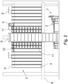
- the storage system 1 is in Fig. 2 in a cut side view and in Fig. 3 shown in a top view.
- the storage system 1 is organized three-dimensionally and comprises a container storage structure 3, a lightweight frame that defines a plurality of storage columns 4. Within these storage columns 4 there are storage spaces arranged vertically one above the other, in which the storage containers 2 can be stacked on top of one another up to a certain height.
- the upper end of the container storage structure 3 is formed by a grid structure 5 designed as a rail grid, on which a number of transport robots 6 operate to operate the storage system 1.
- the grid structure 5 defines a plurality of grid cells corresponding to the storage columns 4.
- the transport robots 6, which can move horizontally on the grid structure 5, each comprise a (in the Fig. 1 and 2 not visible) lift for picking up, transporting and placing storage containers 2, which are stored in the container storage structure 3.
- the storage system 1 further comprises workstations 7, which can be designed as loading stations and/or as order picking stations. Although storage systems of the type in question here have a large number of such workstations in practical operation, for reasons of clarity in the Fig. 1 and 2 only a single workstation 7 is shown. Goods to be stored are transported to the respective workstations 7 via a conveyor line (not shown), or goods to be retrieved or picked are transported away.
- a storage container lifting device 9 which acts as an interface between the workstations 7 and an upper level of the container storage structure 3, is integrated into the interior of the container storage structures 3 so that it is surrounded on all sides by storage columns 4.
- the section in the Fig. 1 and 2 is selected so that both the storage container lifting device 9 and the workstation 7, which which is installed below an intermediate ceiling 8 supporting the container storage structure 3.
- the storage container lifting device 9 could also be integrated into the container storage structure 3 only to such an extent that an outer side of the storage container lifting device 9 is flush with the respective outer side of the container storage structure 3.
- a design in which the storage container lifting device 9 is attached laterally to an outer side of the container storage structure 3 is also feasible.
- the storage container lifting device 9 can also be arranged at a distance from the container storage structure 3, so that no storage space is lost at all within the existing container storage structure 3. The distance to the container storage structure 3 can be bridged using appropriate conveyor devices. It is also possible to provide several separate storage container lifting devices 9.
- the storage container lifting device 9 comprises a (in the Fig. 1 and 2 not visible) lifting platform 10 and is designed to mediate between different levels of the storage system 1 by transporting storage containers 2 in a vertical direction from one level to another level, in particular from a work station 7 to an upper level of the container storage structure 3 and vice versa.
- a lifting platform 10 designed to mediate between different levels of the storage system 1 by transporting storage containers 2 in a vertical direction from one level to another level, in particular from a work station 7 to an upper level of the container storage structure 3 and vice versa.
- the exact functioning of the storage container lifting device 9 is described in detail below.
- the container storage structure 3 is mounted on a platform or intermediate ceiling 8, with a work station 7 being set up in an area below the intermediate ceiling 8.
- a corresponding passage is formed in the intermediate ceiling 8 for the storage container lifting device 9, which, as already mentioned several times, transports storage containers 2 in a vertical direction, in particular between the work station 7 and an upper or the top level of the container storage structure 3.
- the storage container lifting device 9 comprises a lifting and lowering lifting platform 10 for receiving storage containers 2 for vertical transport.
- the lifting platform 10 comprises a conveyor device 13, via which storage containers 2 to be transported in a holding position of the storage container lifting device 9 can be picked up or transported storage containers 2 can be released.
- Two conveyor lines 14a, 14b are provided on the upper transfer level of the container storage structure 3, which can be seen, which are each arranged on opposite sides of the storage container lifting device 9.
- the storage container lifting device 9 is controlled in such a way that the conveyor device 13 discharges the transported storage containers 2 in one direction when the upper transfer level is reached (in the illustration according to Fig. 3 e.g. to the right onto the conveyor line 14b), while the conveyor device 13 receives storage containers 2 from the other direction (ie e.g. from the conveyor line 14a from the left), which must be transported downwards to the work station 7.
- the problem is that the storage system 1 suffers a huge loss of performance when sequences of the type described have to be created directly from the warehouse without any intermediate elements.
- a main reason for the loss of performance is that the waiting times of the transport robots 6 increase because they have to block each other and wait for each other and therefore cannot be used optimally.
- one or more levels of the container storage structure 3 are designed as buffer levels, each with one or more buffer spaces 11 coupled to the storage container lifting device 9 for the intermediate storage of storage containers 2, as shown in particular in the Fig. 1 and 2 can be seen.
- the buffer spaces 11 are designed to be adjacent to the storage container lifting device 9, so that a transfer of storage containers 2 from the lifting platform 10 of the storage container lifting device 9 to the buffer spaces 11 and vice versa is possible.
- the transfer takes place by means of a conveyor device arranged on the respective buffer spaces 11 with a preferably reversible or reversibly adjustable conveying direction, for example in the form of a driven roller conveyor 12.
- buffer spaces 11 directly on the storage container lifting device 9 enables the storage container lifting device 9 to take over the function of sequencing by suitable intermediate storage of storage containers 2 on the buffer spaces 11.
- the required sequencing is implemented by the storage container lifting device 9 by means of appropriate intermediate storage.
- the resulting decoupling of the sequencing from the transport robots 6 means that they can work independently of the specific sequence required and thus more flexibly and quickly.
- all storage levels between the upper transfer level and the work station level i.e. a total of ten levels, are designed as buffer levels with buffer spaces 11, with buffer spaces 11 each arranged on two opposite sides of the storage container lifting device 9.
- the buffer spaces 11 are each designed to be double-deep, so that two storage containers 2 can be temporarily stored per buffer space 11.
- the rack storage 15 is a rack storage 15 which is served with the help of individual transport units equipped with load-handling devices, so-called shuttles 16.
- the shuttles 16 can be designed either as OLS systems (one-level shuttles) or as MLS systems (multi-level shuttles).
- the buffer spaces 11 arranged on one side of the storage container lifting device 9 are designed, on the one hand, to take over storage containers 2 from the storage container lifting device 9 and, on the other hand, to transfer storage containers 2 to the shuttles 16 and/or to take over storage containers from the shuttles 16.
- These buffer locations 11 therefore function as interfaces or transfer points between the container storage structure 3 and the shelf warehouse 15 and thus enable an expansion of the buffer capacity through the shelf warehouse 15.
- storage containers 2 can not only be temporarily stored in the buffer locations 11 coupled to the storage container lifting device 9, but can be expanded to the entire shelf warehouse 15.
- the shuttles 16 can take over storage containers 2 from the respective buffer locations 11 and temporarily store them in the shelf warehouse 15.
- storage containers 2 in which frequently requested articles are stored can advantageously already be kept in the shelf warehouse 15.
- a supply of the (in Fig. 4 not shown) workstations 7 is carried out via the shuttles 16.
- the buffer spaces 11 coupled to the storage container lifting device 9 are integrated into a shelf row 17 of the shelf storage 15. According to a further embodiment, it can be provided that not only the buffer spaces 11, as in Fig. 4 shown, but also the storage container lifting device 9 is integrated into a shelf row 17 of the shelf storage 15, if necessary together with buffer spaces 11 on both sides.
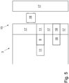
- Fig. 5 shows in a schematic plan view a similar storage system as Fig. 4 , in addition to the embodiment according to Fig. 4 a further storage container lifting device 18 with coupled buffer spaces 19 is provided. It can be provided that, as in connection with Fig. 4 As described, new storage containers 2 from the container storage structure 3 are fed to the shelf warehouse 15 via the buffer spaces 11, while storage containers 2 are removed or fed to the respective workstations via the additional storage container lifting device 18 with coupled buffer spaces 19. In this way, reversible buffer spaces, which are fundamentally susceptible to failure and reduce performance, can be avoided within the shelf warehouse 15.
Landscapes
- Engineering & Computer Science (AREA)
- Mechanical Engineering (AREA)
- Physics & Mathematics (AREA)
- Mathematical Physics (AREA)
- Warehouses Or Storage Devices (AREA)
Claims (11)
- Système de stockage pour le stockage de récipients, comprenant :une structure de grille (5) avec une pluralité de cellules de grille, dans lequel chaque cellule de grille définit une colonne de stockage (4) d'une structure de stockage de récipients (3) disposée en dessous de la structure de grille (5), dans lequel les colonnes de stockage (4) sont conçues pour loger chacune un empilement vertical de récipients de stockage (2),au moins un robot de transport (6), conçu pour se déplacer sur la structure de grille (5), pour la manipulation des récipients de stockage (2), dans lequel le robot de transport (6) comprend des moyens pour le logement, le transport et le dépôt des récipients de stockage (2) logés dans la structure de stockage de récipients (3), ainsi queau moins un dispositif de levage de récipients de stockage (9) avec une plateforme de levage (10) pouvant être levée et abaissée, pour le convoyage vertical de récipients de stockage (2),dans lequel un ou plusieurs niveaux de la structure de stockage de récipients (3) sont conçus comme des niveaux tampons avec chacun un ou plusieurs emplacements tampons (11) se couplant au dispositif de levage de récipients de stockage (9), pour l'entreposage de récipients de stockage (2), caractérisé en ce que la plateforme de levage (10) pouvant être levée et abaissée comprend un dispositif de préhension pour le transfert des récipients de stockage (2) vers les emplacements tampons (11) ainsi que pour la prise en charge des récipients de stockage (2) à partir des emplacements tampons (11).
- Système de stockage selon la revendication 1, caractérisé en ce que les emplacements de stockage (11) sont disposés sur deux côtés opposés du dispositif de levage de récipients de stockage (9).
- Système de stockage selon la revendication 1 ou 2, caractérisé en ce que les emplacements de stockage (11) sur un côté du dispositif de levage de récipients de stockage (9) sont conçus pour l'entreposage des récipients de stockage (2) à stocker dans la structure de stockage de récipients (3) et les emplacements de stockage sur l'autre côté du dispositif de levage de récipients de stockage (9) sont conçus pour l'entreposage des récipients de stockage (2) à déstocker hors de la structure de stockage de récipients (3).
- Système de stockage selon la revendication 1, caractérisé en ce que les emplacements de stockage (11) sont disposés uniquement sur un côté du dispositif de levage de récipients de stockage (9).
- Système de stockage selon l'une des revendications 1 à 4, caractérisé en ce que les emplacements de stockage (11) sont conçus, de manière alternée d'un niveau tampon à un autre, soit pour l'entreposage des récipients de stockage (2) à stocker dans la structure de stockage de récipients (3) soit pour l'entreposage des récipients de stockage (2) à déstocker hors de la structure de stockage de récipients (3).
- Système de stockage selon l'une des revendications 1 à 5, caractérisé en ce qu'un ou plusieurs niveaux tampons comprennent un emplacement tampon (11) qui comprend, pour le transfert des récipients de stockage (2) vers un robot de transport (6) et/ou pour la prise en charge des récipients de stockage (2) par un robot de transport (6), une zone tampon correspondant à une cellule de grille de la structure de grille (5) et librement accessible à partir de la structure de grille (5).
- Système de stockage selon l'une des revendications 1 à 6, caractérisé par au moins un niveau d'emplacement de travail avec un emplacement de travail (7) conçu comme une station de chargement et/ou comme une station de préparation de commande etau moins un niveau de transfert pour le transfert des récipients de stockage (2) de la structure de stockage de récipients (3) vers le dispositif de levage de récipients de stockage (9) ainsi que du dispositif de levage de récipients de stockage (9) vers la structure de stockage de récipients (3),dans lequel le dispositif de levage de récipients de stockage (9) relie le niveau d'emplacement de travail avec le niveau d'emplacement de transfert.
- Système de stockage selon l'une des revendications 1 à 7, caractérisé en ce que le dispositif de levage de récipients de stockage (9) et les emplacements tampons (11) sont conçus comme une seule unité.
- Système de stockage selon l'une des revendications 1 à 8, caractérisé en ce qu'un dispositif de levage de récipients de stockage (9) est disposé sur un côté externe de la structure de stockage de récipients (3) et/ou à l'intérieur de la structure de stockage de récipients (3).
- Système de stockage selon l'une des revendications 1 à 9, comprenant en outre un stockage à rayonnages (15) pouvant être desservi au moyen d'une ou plusieurs navettes (16), dans lequel les emplacements tampons (11) sont conçus pour le transfert des récipients de stockage (2) vers les navettes (16) et/ou pour la prise en charge des récipients de stockage (2) par les navettes (16).
- Système de stockage selon la revendication 10, caractérisé en ce que les emplacements de stockage (11) se couplant au dispositif de levage de récipients de stockage (9) sont intégrés dans une rangée de rayonnages du stockage à rayonnages (15).
Applications Claiming Priority (2)
| Application Number | Priority Date | Filing Date | Title |
|---|---|---|---|
| DE102018218906.4A DE102018218906A1 (de) | 2018-11-06 | 2018-11-06 | Lagersystem zum Lagern von Behältern |
| EP19203903.0A EP3650374B1 (fr) | 2018-11-06 | 2019-10-17 | Système de stockage permettant de stocker des récipients |
Related Parent Applications (2)
| Application Number | Title | Priority Date | Filing Date |
|---|---|---|---|
| EP19203903.0A Division EP3650374B1 (fr) | 2018-11-06 | 2019-10-17 | Système de stockage permettant de stocker des récipients |
| EP19203903.0A Division-Into EP3650374B1 (fr) | 2018-11-06 | 2019-10-17 | Système de stockage permettant de stocker des récipients |
Publications (2)
| Publication Number | Publication Date |
|---|---|
| EP4328154A1 EP4328154A1 (fr) | 2024-02-28 |
| EP4328154B1 true EP4328154B1 (fr) | 2025-01-29 |
Family
ID=68296002
Family Applications (2)
| Application Number | Title | Priority Date | Filing Date |
|---|---|---|---|
| EP23198659.7A Active EP4328154B1 (fr) | 2018-11-06 | 2019-10-17 | Système de stockage permettant de stocker des récipients |
| EP19203903.0A Active EP3650374B1 (fr) | 2018-11-06 | 2019-10-17 | Système de stockage permettant de stocker des récipients |
Family Applications After (1)
| Application Number | Title | Priority Date | Filing Date |
|---|---|---|---|
| EP19203903.0A Active EP3650374B1 (fr) | 2018-11-06 | 2019-10-17 | Système de stockage permettant de stocker des récipients |
Country Status (2)
| Country | Link |
|---|---|
| EP (2) | EP4328154B1 (fr) |
| DE (1) | DE102018218906A1 (fr) |
Families Citing this family (12)
| Publication number | Priority date | Publication date | Assignee | Title |
|---|---|---|---|---|
| NO346009B1 (en) * | 2020-03-31 | 2021-12-20 | Autostore Tech As | Automated storage system having a storage tower in isolating housing |
| WO2022034195A1 (fr) * | 2020-08-14 | 2022-02-17 | Ocado Innovation Limited | Structure d'ossature de grille |
| DE102020128511A1 (de) * | 2020-10-29 | 2022-05-05 | Dematic Gmbh | Lagersystem zum Lagern von Waren in einem dreidimensionalen Lager |
| TWI843186B (zh) * | 2021-08-27 | 2024-05-21 | 大陸商北京極智嘉科技股份有限公司 | 貨架、倉儲系統、轉運機器人及系統、倉儲排程方法及裝置、計算設備、電腦可讀儲存媒體、電腦程式產品 |
| DE102021215079B4 (de) | 2021-12-29 | 2024-10-17 | Gebhardt Fördertechnik GmbH | Lager- und Entnahmesystem sowie Station für ein Lager- und Entnahmesystem |
| DE102022201937A1 (de) | 2022-02-24 | 2023-08-24 | Gebhardt Fördertechnik GmbH | Lager- und Entnahmesystem sowie Verfahren zum Betreiben eines Lager- und Entnahmesystems |
| CN114620387B (zh) * | 2022-02-28 | 2024-04-05 | 北京京东振世信息技术有限公司 | 空单元容器处理方法和装置 |
| EP4353630B1 (fr) | 2022-10-13 | 2025-03-05 | Dematic GmbH | Système de stockage avec un rayonnage de stockage multiniveau |
| EP4428063A1 (fr) * | 2023-03-10 | 2024-09-11 | Gebhardt Fördertechnik GmbH | Système de stockage et de prélèvement et procédé de fonctionnement d'un système de stockage et de prélèvement |
| GB2632104A (en) * | 2023-07-21 | 2025-01-29 | Ocado Innovation Ltd | Storage and retrieval system |
| EP4663578A1 (fr) * | 2024-06-11 | 2025-12-17 | AutoStore Technology AS | Chariot élévateur |
| CN120039544B (zh) * | 2025-03-17 | 2025-11-04 | 山东丰汉机械装备有限公司 | 一种用于木材加工的送料机构 |
Family Cites Families (7)
| Publication number | Priority date | Publication date | Assignee | Title |
|---|---|---|---|---|
| DE2138120C3 (de) * | 1971-07-30 | 1978-07-20 | Enzinger-Union-Werke Ag, 6800 Mannheim | Vorrichtung zum Be- oder Entladen von Paletten mit Schichten von Flaschenkästen oder Flaschenkartons |
| NO334806B1 (no) * | 2012-11-13 | 2014-06-02 | Jakob Hatteland Logistics As | Lagringssystem |
| GB201509921D0 (en) * | 2015-06-08 | 2015-07-22 | Ocado Innovation Ltd | Object storage, handling and retrieving system and method |
| NO345223B1 (en) * | 2016-10-14 | 2020-11-09 | Autostore Tech As | Picking or supply station assembly for storage system and method of transferring an item to and/or from storage system |
| NO344236B1 (en) * | 2017-06-29 | 2019-10-14 | Autostore Tech As | Automated storage and retrieval system comprising different temperature zones and method for moving a container between temperature zones |
| GB201800961D0 (en) * | 2018-01-22 | 2018-03-07 | Ocado Innovation Ltd | System and method for order picking |
| DE102018214214A1 (de) * | 2018-08-22 | 2020-02-27 | Gebhardt Fördertechnik GmbH | Lagersystem zum Lagern von Behältern |
-
2018
- 2018-11-06 DE DE102018218906.4A patent/DE102018218906A1/de not_active Ceased
-
2019
- 2019-10-17 EP EP23198659.7A patent/EP4328154B1/fr active Active
- 2019-10-17 EP EP19203903.0A patent/EP3650374B1/fr active Active
Also Published As
| Publication number | Publication date |
|---|---|
| EP3650374A1 (fr) | 2020-05-13 |
| EP3650374B1 (fr) | 2023-12-06 |
| EP4328154A1 (fr) | 2024-02-28 |
| DE102018218906A1 (de) | 2020-05-07 |
Similar Documents
| Publication | Publication Date | Title |
|---|---|---|
| EP3650374B1 (fr) | Système de stockage permettant de stocker des récipients | |
| EP4219347B1 (fr) | Système de stockage permettant de stocker des récipient | |
| AT512339B1 (de) | Regallagersystem und verfahren zum betreiben desselben | |
| EP3875403B1 (fr) | Procédé de stockage et/ou de retrait d'un produit de stockage dans ou d'un système de stockage, ainsi que système de stockage correspondant | |
| EP2287093B2 (fr) | Système de rayonnage et procédé de fonctionnement d'un système de rayonnage | |
| DE102011014394C5 (de) | Zirkulares Roaming für ein Lager- und Kommissioniersystem | |
| EP4086200B1 (fr) | Procédé d'accès à un récipient dans un système de stockage et de récupération et véhicule de transport destiné à être utilisé dans un système de stockage et de retrait pour récipients, ainsi que système de stockage et de retrait | |
| DE102014003451A1 (de) | Reagalbediengerät mit hochgesetzter Fahrschiene | |
| DE102020212346A1 (de) | Lager- und Entnahmesystem sowie Verfahren zum Betreiben desselben | |
| DE202014100476U1 (de) | Lagerregalanordnung mit stationären Vertikalförderern in stirnseitig angeordneter Vorzone | |
| EP1681247A1 (fr) | Dispositif pour former un ordre défini des porte-charges utilisant un entrepôt transitoire et procédé de stockage intermédiaire | |
| WO2022090033A1 (fr) | Système de stockage pour le stockage de marchandises dans une installation de stockage tridimensionnelle | |
| DE102019211804B4 (de) | Lagersystem zur Speicherung und Abgabe von Ladungsträgern | |
| EP3057887B1 (fr) | Système de stockage pourvu de structures de stockage amenées en rotation dans différents plans | |
| WO2021214079A1 (fr) | Agencement de deux cadres de guidage et de support et d'un véhicule d'ascenseur | |
| EP3473562B1 (fr) | Procédé et technologie de stockage des étagères hautes permettant de stocker la marchandise au moyen du stockage transversal orthogonal | |
| DE102019134776B3 (de) | Verschieberegalanordnung und Verfahren zum Betreiben der Verschieberegalanordnung | |
| WO2021110836A2 (fr) | Système de stockage | |
| DE102023203215B4 (de) | Regalsystem | |
| EP4428063A1 (fr) | Système de stockage et de prélèvement et procédé de fonctionnement d'un système de stockage et de prélèvement | |
| DE102024131148B3 (de) | Verfahren zum sequenzierten Ein- und Auslagern von Packstücken in ein oder aus einem Regallager und entsprechendes Regallagersystem | |
| EP4371907A1 (fr) | Système de navette et procédé de fonctionnement d'un système de navette | |
| DE102023134767A1 (de) | Insektenaufzuchtsystem | |
| WO2025180619A1 (fr) | Système intralogistique | |
| DE2518011A1 (de) | Automatisiertes hohes lagerhaus mit turm-gestell-stapelung von palettisierten guetern |
Legal Events
| Date | Code | Title | Description |
|---|---|---|---|
| PUAI | Public reference made under article 153(3) epc to a published international application that has entered the european phase |
Free format text: ORIGINAL CODE: 0009012 |
|
| STAA | Information on the status of an ep patent application or granted ep patent |
Free format text: STATUS: THE APPLICATION HAS BEEN PUBLISHED |
|
| AC | Divisional application: reference to earlier application |
Ref document number: 3650374 Country of ref document: EP Kind code of ref document: P |
|
| AK | Designated contracting states |
Kind code of ref document: A1 Designated state(s): AL AT BE BG CH CY CZ DE DK EE ES FI FR GB GR HR HU IE IS IT LI LT LU LV MC MK MT NL NO PL PT RO RS SE SI SK SM TR |
|
| STAA | Information on the status of an ep patent application or granted ep patent |
Free format text: STATUS: REQUEST FOR EXAMINATION WAS MADE |
|
| 17P | Request for examination filed |
Effective date: 20240613 |
|
| RBV | Designated contracting states (corrected) |
Designated state(s): AL AT BE BG CH CY CZ DE DK EE ES FI FR GB GR HR HU IE IS IT LI LT LU LV MC MK MT NL NO PL PT RO RS SE SI SK SM TR |
|
| GRAP | Despatch of communication of intention to grant a patent |
Free format text: ORIGINAL CODE: EPIDOSNIGR1 |
|
| STAA | Information on the status of an ep patent application or granted ep patent |
Free format text: STATUS: GRANT OF PATENT IS INTENDED |
|
| INTG | Intention to grant announced |
Effective date: 20240909 |
|
| GRAS | Grant fee paid |
Free format text: ORIGINAL CODE: EPIDOSNIGR3 |
|
| GRAA | (expected) grant |
Free format text: ORIGINAL CODE: 0009210 |
|
| STAA | Information on the status of an ep patent application or granted ep patent |
Free format text: STATUS: THE PATENT HAS BEEN GRANTED |
|
| P01 | Opt-out of the competence of the unified patent court (upc) registered |
Free format text: CASE NUMBER: APP_66766/2024 Effective date: 20241217 |
|
| AC | Divisional application: reference to earlier application |
Ref document number: 3650374 Country of ref document: EP Kind code of ref document: P |
|
| AK | Designated contracting states |
Kind code of ref document: B1 Designated state(s): AL AT BE BG CH CY CZ DE DK EE ES FI FR GB GR HR HU IE IS IT LI LT LU LV MC MK MT NL NO PL PT RO RS SE SI SK SM TR |
|
| REG | Reference to a national code |
Ref country code: GB Ref legal event code: FG4D Free format text: NOT ENGLISH |
|
| REG | Reference to a national code |
Ref country code: CH Ref legal event code: EP |
|
| REG | Reference to a national code |
Ref country code: DE Ref legal event code: R096 Ref document number: 502019012899 Country of ref document: DE |
|
| REG | Reference to a national code |
Ref country code: IE Ref legal event code: FG4D Free format text: LANGUAGE OF EP DOCUMENT: GERMAN |
|
| REG | Reference to a national code |
Ref country code: NL Ref legal event code: MP Effective date: 20250129 |
|
| PG25 | Lapsed in a contracting state [announced via postgrant information from national office to epo] |
Ref country code: NL Free format text: LAPSE BECAUSE OF FAILURE TO SUBMIT A TRANSLATION OF THE DESCRIPTION OR TO PAY THE FEE WITHIN THE PRESCRIBED TIME-LIMIT Effective date: 20250129 |
|
| PG25 | Lapsed in a contracting state [announced via postgrant information from national office to epo] |
Ref country code: RS Free format text: LAPSE BECAUSE OF FAILURE TO SUBMIT A TRANSLATION OF THE DESCRIPTION OR TO PAY THE FEE WITHIN THE PRESCRIBED TIME-LIMIT Effective date: 20250429 |
|
| PG25 | Lapsed in a contracting state [announced via postgrant information from national office to epo] |
Ref country code: FI Free format text: LAPSE BECAUSE OF FAILURE TO SUBMIT A TRANSLATION OF THE DESCRIPTION OR TO PAY THE FEE WITHIN THE PRESCRIBED TIME-LIMIT Effective date: 20250129 |
|
| PG25 | Lapsed in a contracting state [announced via postgrant information from national office to epo] |
Ref country code: PL Free format text: LAPSE BECAUSE OF FAILURE TO SUBMIT A TRANSLATION OF THE DESCRIPTION OR TO PAY THE FEE WITHIN THE PRESCRIBED TIME-LIMIT Effective date: 20250129 |
|
| PG25 | Lapsed in a contracting state [announced via postgrant information from national office to epo] |
Ref country code: ES Free format text: LAPSE BECAUSE OF FAILURE TO SUBMIT A TRANSLATION OF THE DESCRIPTION OR TO PAY THE FEE WITHIN THE PRESCRIBED TIME-LIMIT Effective date: 20250129 |
|
| REG | Reference to a national code |
Ref country code: LT Ref legal event code: MG9D |
|
| PG25 | Lapsed in a contracting state [announced via postgrant information from national office to epo] |
Ref country code: IS Free format text: LAPSE BECAUSE OF FAILURE TO SUBMIT A TRANSLATION OF THE DESCRIPTION OR TO PAY THE FEE WITHIN THE PRESCRIBED TIME-LIMIT Effective date: 20250529 Ref country code: NO Free format text: LAPSE BECAUSE OF FAILURE TO SUBMIT A TRANSLATION OF THE DESCRIPTION OR TO PAY THE FEE WITHIN THE PRESCRIBED TIME-LIMIT Effective date: 20250429 |
|
| PG25 | Lapsed in a contracting state [announced via postgrant information from national office to epo] |
Ref country code: HR Free format text: LAPSE BECAUSE OF FAILURE TO SUBMIT A TRANSLATION OF THE DESCRIPTION OR TO PAY THE FEE WITHIN THE PRESCRIBED TIME-LIMIT Effective date: 20250129 |
|
| PG25 | Lapsed in a contracting state [announced via postgrant information from national office to epo] |
Ref country code: LV Free format text: LAPSE BECAUSE OF FAILURE TO SUBMIT A TRANSLATION OF THE DESCRIPTION OR TO PAY THE FEE WITHIN THE PRESCRIBED TIME-LIMIT Effective date: 20250129 Ref country code: PT Free format text: LAPSE BECAUSE OF FAILURE TO SUBMIT A TRANSLATION OF THE DESCRIPTION OR TO PAY THE FEE WITHIN THE PRESCRIBED TIME-LIMIT Effective date: 20250529 |
|
| PG25 | Lapsed in a contracting state [announced via postgrant information from national office to epo] |
Ref country code: BG Free format text: LAPSE BECAUSE OF FAILURE TO SUBMIT A TRANSLATION OF THE DESCRIPTION OR TO PAY THE FEE WITHIN THE PRESCRIBED TIME-LIMIT Effective date: 20250129 Ref country code: GR Free format text: LAPSE BECAUSE OF FAILURE TO SUBMIT A TRANSLATION OF THE DESCRIPTION OR TO PAY THE FEE WITHIN THE PRESCRIBED TIME-LIMIT Effective date: 20250430 |
|
| PG25 | Lapsed in a contracting state [announced via postgrant information from national office to epo] |
Ref country code: SE Free format text: LAPSE BECAUSE OF FAILURE TO SUBMIT A TRANSLATION OF THE DESCRIPTION OR TO PAY THE FEE WITHIN THE PRESCRIBED TIME-LIMIT Effective date: 20250129 |
|
| PG25 | Lapsed in a contracting state [announced via postgrant information from national office to epo] |
Ref country code: SM Free format text: LAPSE BECAUSE OF FAILURE TO SUBMIT A TRANSLATION OF THE DESCRIPTION OR TO PAY THE FEE WITHIN THE PRESCRIBED TIME-LIMIT Effective date: 20250129 |
|
| PG25 | Lapsed in a contracting state [announced via postgrant information from national office to epo] |
Ref country code: DK Free format text: LAPSE BECAUSE OF FAILURE TO SUBMIT A TRANSLATION OF THE DESCRIPTION OR TO PAY THE FEE WITHIN THE PRESCRIBED TIME-LIMIT Effective date: 20250129 |
|
| PG25 | Lapsed in a contracting state [announced via postgrant information from national office to epo] |
Ref country code: IT Free format text: LAPSE BECAUSE OF FAILURE TO SUBMIT A TRANSLATION OF THE DESCRIPTION OR TO PAY THE FEE WITHIN THE PRESCRIBED TIME-LIMIT Effective date: 20250129 |
|
| PG25 | Lapsed in a contracting state [announced via postgrant information from national office to epo] |
Ref country code: EE Free format text: LAPSE BECAUSE OF FAILURE TO SUBMIT A TRANSLATION OF THE DESCRIPTION OR TO PAY THE FEE WITHIN THE PRESCRIBED TIME-LIMIT Effective date: 20250129 Ref country code: CZ Free format text: LAPSE BECAUSE OF FAILURE TO SUBMIT A TRANSLATION OF THE DESCRIPTION OR TO PAY THE FEE WITHIN THE PRESCRIBED TIME-LIMIT Effective date: 20250129 |
|
| PG25 | Lapsed in a contracting state [announced via postgrant information from national office to epo] |
Ref country code: RO Free format text: LAPSE BECAUSE OF FAILURE TO SUBMIT A TRANSLATION OF THE DESCRIPTION OR TO PAY THE FEE WITHIN THE PRESCRIBED TIME-LIMIT Effective date: 20250129 |
|
| PG25 | Lapsed in a contracting state [announced via postgrant information from national office to epo] |
Ref country code: SK Free format text: LAPSE BECAUSE OF FAILURE TO SUBMIT A TRANSLATION OF THE DESCRIPTION OR TO PAY THE FEE WITHIN THE PRESCRIBED TIME-LIMIT Effective date: 20250129 |
|
| REG | Reference to a national code |
Ref country code: DE Ref legal event code: R097 Ref document number: 502019012899 Country of ref document: DE |
|
| REG | Reference to a national code |
Ref country code: CH Ref legal event code: U11 Free format text: ST27 STATUS EVENT CODE: U-0-0-U10-U11 (AS PROVIDED BY THE NATIONAL OFFICE) Effective date: 20251101 |
|
| PLBE | No opposition filed within time limit |
Free format text: ORIGINAL CODE: 0009261 |
|
| STAA | Information on the status of an ep patent application or granted ep patent |
Free format text: STATUS: NO OPPOSITION FILED WITHIN TIME LIMIT |
|
| 26N | No opposition filed |
Effective date: 20251030 |
|
| PGFP | Annual fee paid to national office [announced via postgrant information from national office to epo] |
Ref country code: GB Payment date: 20251024 Year of fee payment: 7 |
|
| PGFP | Annual fee paid to national office [announced via postgrant information from national office to epo] |
Ref country code: AT Payment date: 20251021 Year of fee payment: 7 |
|
| PGFP | Annual fee paid to national office [announced via postgrant information from national office to epo] |
Ref country code: FR Payment date: 20251022 Year of fee payment: 7 |
|
| PGFP | Annual fee paid to national office [announced via postgrant information from national office to epo] |
Ref country code: CH Payment date: 20251101 Year of fee payment: 7 |
|
| PGFP | Annual fee paid to national office [announced via postgrant information from national office to epo] |
Ref country code: DE Payment date: 20251223 Year of fee payment: 7 |