EP4328428B1 - Kraftfahrzeug mit einem verbrennungsmotor aufweisend eine seitliche abgasauslassöffnung - Google Patents
Kraftfahrzeug mit einem verbrennungsmotor aufweisend eine seitliche abgasauslassöffnung Download PDFInfo
- Publication number
- EP4328428B1 EP4328428B1 EP23192866.4A EP23192866A EP4328428B1 EP 4328428 B1 EP4328428 B1 EP 4328428B1 EP 23192866 A EP23192866 A EP 23192866A EP 4328428 B1 EP4328428 B1 EP 4328428B1
- Authority
- EP
- European Patent Office
- Prior art keywords
- car
- internal combustion
- combustion engine
- silencer
- transmission
- Prior art date
- Legal status (The legal status is an assumption and is not a legal conclusion. Google has not performed a legal analysis and makes no representation as to the accuracy of the status listed.)
- Active
Links
Images







Classifications
-
- F—MECHANICAL ENGINEERING; LIGHTING; HEATING; WEAPONS; BLASTING
- F01—MACHINES OR ENGINES IN GENERAL; ENGINE PLANTS IN GENERAL; STEAM ENGINES
- F01N—GAS-FLOW SILENCERS OR EXHAUST APPARATUS FOR MACHINES OR ENGINES IN GENERAL; GAS-FLOW SILENCERS OR EXHAUST APPARATUS FOR INTERNAL-COMBUSTION ENGINES
- F01N13/00—Exhaust or silencing apparatus characterised by constructional features
-
- B—PERFORMING OPERATIONS; TRANSPORTING
- B60—VEHICLES IN GENERAL
- B60K—ARRANGEMENT OR MOUNTING OF PROPULSION UNITS OR OF TRANSMISSIONS IN VEHICLES; ARRANGEMENT OR MOUNTING OF PLURAL DIVERSE PRIME-MOVERS IN VEHICLES; AUXILIARY DRIVES FOR VEHICLES; INSTRUMENTATION OR DASHBOARDS FOR VEHICLES; ARRANGEMENTS IN CONNECTION WITH COOLING, AIR INTAKE, GAS EXHAUST OR FUEL SUPPLY OF PROPULSION UNITS IN VEHICLES
- B60K1/00—Arrangement or mounting of electrical propulsion units
-
- B—PERFORMING OPERATIONS; TRANSPORTING
- B60—VEHICLES IN GENERAL
- B60K—ARRANGEMENT OR MOUNTING OF PROPULSION UNITS OR OF TRANSMISSIONS IN VEHICLES; ARRANGEMENT OR MOUNTING OF PLURAL DIVERSE PRIME-MOVERS IN VEHICLES; AUXILIARY DRIVES FOR VEHICLES; INSTRUMENTATION OR DASHBOARDS FOR VEHICLES; ARRANGEMENTS IN CONNECTION WITH COOLING, AIR INTAKE, GAS EXHAUST OR FUEL SUPPLY OF PROPULSION UNITS IN VEHICLES
- B60K13/00—Arrangement in connection with combustion air intake or gas exhaust of propulsion units
- B60K13/04—Arrangement in connection with combustion air intake or gas exhaust of propulsion units concerning exhaust
-
- B—PERFORMING OPERATIONS; TRANSPORTING
- B60—VEHICLES IN GENERAL
- B60K—ARRANGEMENT OR MOUNTING OF PROPULSION UNITS OR OF TRANSMISSIONS IN VEHICLES; ARRANGEMENT OR MOUNTING OF PLURAL DIVERSE PRIME-MOVERS IN VEHICLES; AUXILIARY DRIVES FOR VEHICLES; INSTRUMENTATION OR DASHBOARDS FOR VEHICLES; ARRANGEMENTS IN CONNECTION WITH COOLING, AIR INTAKE, GAS EXHAUST OR FUEL SUPPLY OF PROPULSION UNITS IN VEHICLES
- B60K5/00—Arrangement or mounting of internal-combustion or jet-propulsion units
-
- F—MECHANICAL ENGINEERING; LIGHTING; HEATING; WEAPONS; BLASTING
- F01—MACHINES OR ENGINES IN GENERAL; ENGINE PLANTS IN GENERAL; STEAM ENGINES
- F01N—GAS-FLOW SILENCERS OR EXHAUST APPARATUS FOR MACHINES OR ENGINES IN GENERAL; GAS-FLOW SILENCERS OR EXHAUST APPARATUS FOR INTERNAL-COMBUSTION ENGINES
- F01N13/00—Exhaust or silencing apparatus characterised by constructional features
- F01N13/08—Other arrangements or adaptations of exhaust conduits
-
- F—MECHANICAL ENGINEERING; LIGHTING; HEATING; WEAPONS; BLASTING
- F01—MACHINES OR ENGINES IN GENERAL; ENGINE PLANTS IN GENERAL; STEAM ENGINES
- F01N—GAS-FLOW SILENCERS OR EXHAUST APPARATUS FOR MACHINES OR ENGINES IN GENERAL; GAS-FLOW SILENCERS OR EXHAUST APPARATUS FOR INTERNAL-COMBUSTION ENGINES
- F01N13/00—Exhaust or silencing apparatus characterised by constructional features
- F01N13/08—Other arrangements or adaptations of exhaust conduits
- F01N13/082—Other arrangements or adaptations of exhaust conduits of tailpipe, e.g. with means for mixing air with exhaust for exhaust cooling, dilution or evacuation
-
- F—MECHANICAL ENGINEERING; LIGHTING; HEATING; WEAPONS; BLASTING
- F01—MACHINES OR ENGINES IN GENERAL; ENGINE PLANTS IN GENERAL; STEAM ENGINES
- F01N—GAS-FLOW SILENCERS OR EXHAUST APPARATUS FOR MACHINES OR ENGINES IN GENERAL; GAS-FLOW SILENCERS OR EXHAUST APPARATUS FOR INTERNAL-COMBUSTION ENGINES
- F01N13/00—Exhaust or silencing apparatus characterised by constructional features
- F01N13/18—Construction facilitating manufacture, assembly, or disassembly
- F01N13/1805—Fixing exhaust manifolds, exhaust pipes or pipe sections to each other, to engine or to vehicle body
-
- B—PERFORMING OPERATIONS; TRANSPORTING
- B60—VEHICLES IN GENERAL
- B60K—ARRANGEMENT OR MOUNTING OF PROPULSION UNITS OR OF TRANSMISSIONS IN VEHICLES; ARRANGEMENT OR MOUNTING OF PLURAL DIVERSE PRIME-MOVERS IN VEHICLES; AUXILIARY DRIVES FOR VEHICLES; INSTRUMENTATION OR DASHBOARDS FOR VEHICLES; ARRANGEMENTS IN CONNECTION WITH COOLING, AIR INTAKE, GAS EXHAUST OR FUEL SUPPLY OF PROPULSION UNITS IN VEHICLES
- B60K1/00—Arrangement or mounting of electrical propulsion units
- B60K2001/001—Arrangement or mounting of electrical propulsion units one motor mounted on a propulsion axle for rotating right and left wheels of this axle
-
- B—PERFORMING OPERATIONS; TRANSPORTING
- B60—VEHICLES IN GENERAL
- B60K—ARRANGEMENT OR MOUNTING OF PROPULSION UNITS OR OF TRANSMISSIONS IN VEHICLES; ARRANGEMENT OR MOUNTING OF PLURAL DIVERSE PRIME-MOVERS IN VEHICLES; AUXILIARY DRIVES FOR VEHICLES; INSTRUMENTATION OR DASHBOARDS FOR VEHICLES; ARRANGEMENTS IN CONNECTION WITH COOLING, AIR INTAKE, GAS EXHAUST OR FUEL SUPPLY OF PROPULSION UNITS IN VEHICLES
- B60K5/00—Arrangement or mounting of internal-combustion or jet-propulsion units
- B60K2005/003—Arrangement or mounting of internal-combustion or jet-propulsion units the internal combustion or jet propulsion unit is arranged between the front and the rear axle
-
- F—MECHANICAL ENGINEERING; LIGHTING; HEATING; WEAPONS; BLASTING
- F01—MACHINES OR ENGINES IN GENERAL; ENGINE PLANTS IN GENERAL; STEAM ENGINES
- F01N—GAS-FLOW SILENCERS OR EXHAUST APPARATUS FOR MACHINES OR ENGINES IN GENERAL; GAS-FLOW SILENCERS OR EXHAUST APPARATUS FOR INTERNAL-COMBUSTION ENGINES
- F01N1/00—Silencing apparatus characterised by method of silencing
- F01N1/02—Silencing apparatus characterised by method of silencing by using resonance
-
- F—MECHANICAL ENGINEERING; LIGHTING; HEATING; WEAPONS; BLASTING
- F01—MACHINES OR ENGINES IN GENERAL; ENGINE PLANTS IN GENERAL; STEAM ENGINES
- F01N—GAS-FLOW SILENCERS OR EXHAUST APPARATUS FOR MACHINES OR ENGINES IN GENERAL; GAS-FLOW SILENCERS OR EXHAUST APPARATUS FOR INTERNAL-COMBUSTION ENGINES
- F01N13/00—Exhaust or silencing apparatus characterised by constructional features
- F01N13/011—Exhaust or silencing apparatus characterised by constructional features having two or more purifying devices arranged in parallel
-
- F—MECHANICAL ENGINEERING; LIGHTING; HEATING; WEAPONS; BLASTING
- F01—MACHINES OR ENGINES IN GENERAL; ENGINE PLANTS IN GENERAL; STEAM ENGINES
- F01N—GAS-FLOW SILENCERS OR EXHAUST APPARATUS FOR MACHINES OR ENGINES IN GENERAL; GAS-FLOW SILENCERS OR EXHAUST APPARATUS FOR INTERNAL-COMBUSTION ENGINES
- F01N2340/00—Dimensional characteristics of the exhaust system, e.g. length, diameter or volume of the exhaust apparatus; Spatial arrangements of exhaust apparatuses
- F01N2340/04—Arrangement of the exhaust system relative to a vehicle or parts thereof
-
- F—MECHANICAL ENGINEERING; LIGHTING; HEATING; WEAPONS; BLASTING
- F01—MACHINES OR ENGINES IN GENERAL; ENGINE PLANTS IN GENERAL; STEAM ENGINES
- F01N—GAS-FLOW SILENCERS OR EXHAUST APPARATUS FOR MACHINES OR ENGINES IN GENERAL; GAS-FLOW SILENCERS OR EXHAUST APPARATUS FOR INTERNAL-COMBUSTION ENGINES
- F01N2470/00—Structure or shape of exhaust gas passages, pipes or tubes
- F01N2470/14—Plurality of outlet tubes, e.g. in parallel or with different length
Definitions
- the present invention relates to a car provided with an internal combustion engine.
- the present invention is advantageously applied to a car provided with an internal combustion engine arranged in a central/rear position (i.e., behind the passenger compartment), to which the following discussion will make explicit reference without thereby losing generality.
- the exhaust system comprises (at least) a silencer which is arranged in a rear position and has (at least) an outlet opening which is configured to release the exhaust gases into the atmosphere and is located at the rear area of the car.
- the noise of the internal combustion engine which is perceived inside the passenger compartment is important. That is to say, an important component in the assessment of a high-performance sports car is the “ quality " of the sound emitted at the exhaust (not only and not so much in terms of sound intensity, but above all in terms of the " pleasantness " of the sound), i.e., the degree of satisfaction in using a high-performance sports car is also significantly influenced by the " quality " of the sound emitted at the exhaust.
- variable-geometry exhaust system i.e., an exhaust system provided with one or more electrically or pneumatically piloted valves which allow the path of the exhaust gases (and thus the sound) along the exhaust system to be modified; as a result, in use, the electronic control unit of the engine modifies the geometry of the exhaust system in real time to try to always offer a sound emitted at the exhaust which corresponds to the expectations of the car's users and, of course, is compatible with reaching the homologation targets on the intensity of the exhaust noise level.
- turbocharged engines are penalised because the presence of the turbine along the exhaust duct and the compressor along the intake duct add a filter and lower the sound levels of both the exhaust and the intake.
- GPF gasoline Particulate Filter
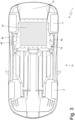
- the exhaust duct is arranged externally in an asymmetrical manner on one side of the car and ends in an outlet opening which is located between a rear drive wheel and a door.
- twin exhaust ducts are provided, each of which ends in an outlet opening which is arranged at one side of the car and is located between a rear drive wheel and a door.
- the aim of the present invention is to provide a car provided with an internal combustion engine which is easy and inexpensive to manufacture and which is free of the drawbacks described above, i.e., it allows a natural and overall pleasant exhaust noise to be perceived inside the passenger compartment according to the expectations of the driver and any passengers.
- a car provided with an optionally hydrogen-powered internal combustion engine is provided in accordance with the appended claims.
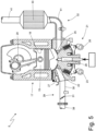
- the number 1 overall indicates a hybrid car (i.e., with hybrid propulsion) provided with two front drive wheels 2 receiving drive torque from (at least) one electric machine 3 (illustrated schematically in figure 4 ) and two rear drive wheels 4 receiving drive torque from an internal combustion engine 5 (illustrated schematically in figure 4 ).
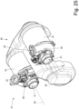
- the electric machine 3 is connected to the two front drive wheels 2 by means of a transmission system (of known type and not illustrated) provided with a front differential; similarly, the internal combustion engine 5 is also connected to the two rear drive wheels 4 by means of a transmission system 6 provided with a transmission 7 and a rear differential 8 (illustrated schematically in figure 15 ).
- the car 1 comprises a bottom 14 which forms the lowest part of the car 1 and in use is facing a road surface on which the car 1 moves.
- the internal combustion engine 5 is powered by hydrogen (or also another gaseous fuel). According to a different embodiment, the internal combustion engine 5 is powered by petrol (or also another liquid fuel).
- the intake system 29 comprises twin, separate intake ducts 34 which are arranged on the two sides of the car 1 (i.e., one intake duct 34 is arranged on the right side and the other intake duct 34 is arranged on the left side) and originates from respective air inlets 35 obtained through the body 12.
- An air filter 36 is arranged along each intake duct 34 near the respective air inlet 35.
- Each intake duct 34 terminates in a compressor unit 37 which increases the air pressure to increase the volumetric efficiency of the cylinders 18.
- a sole (single) intake duct 38 originates from the compressor unit 37, which terminates in the intake manifold 30 after passing through two intercoolers 39 and 40 arranged in series.
- the silencer 44 has a single final exhaust pipe 45 which opens into an outlet opening 46; according to other embodiments not illustrated, the silencer 44 has two or more final pipes 45, each of which opens into a corresponding outlet opening 46.
- the compressor unit 37 (intended for use in the supercharged internal combustion engine 5) comprises a single shaft 47 mounted rotatably about a rotation axis 48.
- the shaft 47 (thus the rotation axis 48) is oriented transversely; according to a different embodiment not illustrated, the shaft 47 (thus the rotation axis 48) is oriented longitudinally or is inclined (non-parallel) both relative to the longitudinal direction and relative to the transverse direction.
- the compressor unit 37 comprises twin (identical) compressors 49, each of which is integral with the shaft 47 to rotate together with the shaft 47 and is configured to compress air intended to be sucked in by the supercharged internal combustion engine 5; in particular, each compressor 49 receives air from a respective intake duct 34 (i.e., each intake duct 34 terminates in a corresponding compressor 49).
- the compressor unit 37 comprises a single common electric motor 50 which is integral with the shaft 47 to bring the shaft 47 into rotation (and thus to bring both compressors 49 mounted on the shaft 47 into rotation).
- the electric motor 50 is arranged between the two compressors 49 and is perfectly equidistant from the two compressors 49; according to a different embodiment not illustrated, the electric motor 50 is arranged on one side with respect to both compressors 49 (i.e., it is closer to one compressor 49 and is farther from the other compressor 49).
- each compressor 49 comprises an axial inlet 51 arranged on the opposite side of the shaft 47 and connected to a respective intake duct 34 and a radial outlet 52.
- the compressor unit 37 comprises a joining duct 53 (illustrated in figures 9-12 ) which is connected to both outlets 52 of the two compressors 49 to receive and join the compressed air from both compressors 49; the joining duct 53 terminates in the intake duct 38, i.e., the intake duct 38 starts from the joining duct 53 to receive and join the compressed air from both compressors 49.
- the joining duct 53 is oriented transversely; according to a different embodiment not illustrated, the joining duct 53 is oriented longitudinally or is inclined (non-parallel) both relative to the longitudinal direction and relative to the transverse direction.
- the joining duct 53 is oriented parallel to the shaft 47 (thus to the rotation axis 48); according to a different embodiment not illustrated, the joining duct 53 is not oriented parallel to the shaft 47, thus to the rotation axis 48).
- the turbine unit 42 comprises two twin (identical) turbines 43 which drive the same electric generator 54 together.
- the two turbines 43 are arranged side by side and have two respective rotation axes 55 which are parallel to each other and spaced apart.
- the turbine unit 42 comprises a transmission device 56 which connects both turbines 43 to the same electric generator 54.
- the transmission device 56 comprises two toothed gears, each of which is integral with the shaft of a corresponding turbine 43 to receive the rotary motion from the turbine 43, and a connecting element (a toothed belt, a chain, a cascade of gearings) which connects the two toothed gears together in such a way as to make both toothed gears rotate together and at the same speed.
- a toothed gear of the two toothed gears of the transmission device 56 is directly coupled to a shaft of the electric generator 54 so that the electric generator 54 rotates at the same rotation speed as the two turbines 43; alternatively, a toothed gear of the two toothed gears of the transmission device 56 is connected to the shaft of the electric generator 54 by means of the interposition of a speed reducer (typically with gearings) such that the electric generator 54 rotates at a lower rotation speed than the rotation speed of the two turbines 43.
- a speed reducer typically with gearings
- the electric generator 54 is coaxial to a turbine 43; i.e., one turbine 43 and the electric generator 54 rotate about the same first rotation axis 55 while the other turbine 43 rotates about a second rotation axis 55 which is parallel to, and spaced from, the first rotation axis 55.
- each turbine 43 is identical and are of the centrifugal type.
- each turbine 43 comprises a radial inlet 57 connected to one side of the respective exhaust duct 41 and an axial outlet 52 arranged on the opposite side of the transmission device 56 and connected to another side (which opens into the silencer 44) of the respective exhaust duct 41.
- the silencer 41 is arranged next to a cylinder block (consisting of the crankcase 17 and cylinder head 21) of the internal combustion engine 5 (on the exhaust valve 25 side).
- the outlet opening 46 of the silencer 41 is obtained through a sidewall of the car 1 (as illustrated in figure 1 ) or, according to an alternative embodiment, through the bottom 14 of the car 1 (as illustrated in figure 3 ).
- the outlet opening 46 of the silencer 44 is arranged asymmetrically at only one side of the car 1 and is located between a rear wheel 4 and a door 13.
- the outlet opening 46 of the silencer 44 is arranged on the side where the driver's station 16 is located, so that the driver sitting in the driver's station 16 is near the outlet opening 46 of the silencer 44 and is thus in the best position to optimally hear the noise diffused through the outlet opening 46 of the silencer 44.
- the outlet opening 46 of the silencer 44 is obtained through a sidewall of the body 12, while in the alternative embodiment illustrated in figure 3 , the outlet opening 46 of the silencer 44 is obtained through the bottom 14.
- the silencer 44 comprises a single outlet opening 46; according to other embodiments not illustrated, the silencer 44 comprises several outlet openings 46 which may be more or less side-by-side (optionally it is also possible for one outlet opening 46 of the silencer 44 to be obtained through a sidewall of the body 12 while the other outlet opening 46 of the silencer 44 is obtained through the bottom 14).
- the silencer 44 is arranged on one side of the car 1 alongside a cylinder block (consisting of the crankcase 17 and cylinder head 21) of the internal combustion engine 5 and in front of a rear drive wheel 4.
- the turbine unit 42 is arranged alongside a cylinder block (consisting of the crankcase 17 and cylinder head 21) of the internal combustion engine 5 (on the exhaust valve 25 side).
- the turbine unit 42 is arranged between the internal combustion engine 5 (i.e., between the cylinder block consisting of the crankcase 17 and cylinder head 21) and the silencer 44; thereby, the exhaust ducts 41 are particularly short and relatively untwisted.
- the compressor unit 37 (comprising the twin compressors 49) is connected between the two intake ducts 34 and 38, is arranged behind the cylinder block (comprising the crankcase 17 and cylinder head 21) of the internal combustion engine 5, is arranged higher than the cylinder block of the internal combustion engine 5, and is driven by the electric motor 50.
- the compressor unit 37 (comprising the two twin compressors 49) is arranged at the rear behind the intercooler 39 (i.e., the two compressors 49 of the compressor unit 37 are arranged at the rear behind the intercooler 39).
- the intercooler 39 is horizontally oriented and is arranged behind (at the rear) of the cylinder block (consisting of the crankcase 17 and cylinder head 21) of the internal combustion engine 5; in particular, the intercooler 39 is arranged higher than the cylinder block of the internal combustion engine 5 and is located behind the cylinder block of the internal combustion engine 5.
- the internal combustion engine 5 comprises a dry sump lubrication circuit 59 which circulates a lubricating oil in all the moving parts of the internal combustion engine 5.
- the lubrication circuit 59 comprises a delivery lubrication pump 60 configured to circulate the lubricating oil; i.e., the delivery lubrication pump 60 draws lubricating oil from an oil tank to send the lubricating oil inside the cylinder block (consisting of the crankcase 17 and cylinder head 21).
- the two recovery lubrication pumps 61 are arranged on opposite sides of the cylinder head 21, so that the lubricating oil is drawn from opposite areas of the cylinder head 21.
- the transmission 7 is directly connected to the drive shaft 20 of the internal combustion engine 5, is aligned with the internal combustion engine 5, and is arranged behind the internal combustion engine 5.
- the transmission 7 is vertically aligned with an upper part of the cylinder block of the internal combustion engine 5; i.e., the transmission 7 is vertically aligned with the upper part of the crankcase 17.
- the transmission 7 is dual-clutch and is interposed between the drive shaft 20 of the internal combustion engine 5 and the rear drive wheels 4.
- the transmission 7 comprises a drum 64 which is brought in rotation by the drive shaft 20 and two clutches 65 contained one next to the other in the drum 64 to receive motion from the drum 64.
- the transmission 7 comprises two primary shafts 66 which are coaxial with each other, are inserted one inside the other, and are each connected to a corresponding clutch 65 to receive motion from the corresponding clutch 65.
- Each clutch 65 comprises driving discs which are integral with the drum 64 (thus they always rotate together with the drive shaft 20 to which the drum 64 is constrained) and driving discs which are interspersed with the driving discs and are integral with the corresponding primary shafts 66 (thus they always rotate together with the corresponding primary shafts 66).
- the drum 64 of the transmission 7 with dual-clutch 65 is arranged on the opposite side of the internal combustion engine 5 (i.e., the drive shaft 20) relative to the two primary shafts 66; furthermore, the transmission 7 with dual-clutch 65 comprises a transmission shaft 67 which connects the drive shaft 20 to the drum 64, is coaxial to the two primary shafts 66, and is inserted within the two primary shafts 66.
- the transmission shaft 67 terminates at an end wall of the drum 64 and is constrained to the end wall of the drum 64.
- a first primary shaft 66 is arranged on the outside, the transmission shaft 67 is arranged on the inside, and the other (second) primary shaft 66 is arranged between the transmission shaft 67 and the first primary shaft 66.
- the transmission shaft 67 which is in the centre
- the two primary shafts 66 which are inserted one inside the other and both surround the transmission shaft 67.
- the primary shafts 66 and the transmission shaft 67 of the transmission 7 are coaxial with the drive shaft 20 of the internal combustion engine 5; i.e., the internal combustion engine 5 is aligned with the transmission 7.
- the transmission 7 with dual-clutch 65 comprises a single secondary shaft 68 connected to the differential 8 which transmits motion to the rear drive wheels 4; according to an alternative and equivalent embodiment, the dual-clutch transmission 7 comprises two secondary shafts 68 both connected to the differential 8. A pair of axle shafts 69, each of which is integral with a rear drive wheel 4, depart from the differential 8.
- the transmission 7 has seven forward gears indicated with Roman numerals (first gear I, second gear II, third gear III, fourth gear IV, fifth gear V, sixth gear VI and seventh gear VII) and one reverse gear (indicated with the letter R).
- Each primary shaft 66 and secondary shaft 68 is mechanically coupled to each other by means of a plurality of gearings, each of which defines a respective gear and comprises a primary toothed gear 70 mounted on the primary shaft 66 and a secondary toothed gear 71 mounted on the secondary shaft 68.
- Each primary toothed gear 70 is keyed to a respective primary shaft 66 to always rotate integrally with the primary shaft 66 and permanently meshes with the respective secondary toothed gear 71; instead, each secondary toothed gear 71 is mounted idle on the secondary shaft 68.
- the transmission 7 comprises four dual synchronisers 72, each of which is coaxially mounted on the secondary shaft 68, is arranged between two secondary toothed gears 19, and is adapted to be actuated to alternately engage the two respective secondary toothed gears 19 to the secondary shaft 68 (i.e., to alternately make the two respective secondary toothed gears 19 angularly integral with the secondary shaft 68).
- each synchroniser 72 can be moved in one direction to engage a secondary toothed gear 71 to the secondary shaft 68, or it can be moved in the other direction to engage the other secondary toothed gear 71 to the secondary shaft 68.
- the car 1 comprises a containing body 73 which (also) contains the dual-clutch transmission 7 therein and has a tapered shape towards the rear so that the height of the containing body 73 progressively reduces from the front to the rear. That is, a front wall of the containing body 73 has a greater extension in height than a rear wall of the containing body 73.
- the containing body 73 has a bottom wall 74 at the bottom which is inclined relative to the horizontal due to the tapered shape of the containing body 73.
- the differential 8 (which receives motion from the secondary shaft 68 of the transmission 7 and transmits the motion to the two rear drive wheels 4 by means of the two respective axle shafts 69) is arranged inside the containing body 73 at the front and below the transmission 7.
- the two axle shafts 69 exit laterally from the containing body 73.
- the transmission 7 is directly connected to the drive shaft 20 of the internal combustion engine 5, is aligned with the internal combustion engine 5 (i.e., the primary shafts 66 and the transmission shaft 67 of the transmission 7 are coaxial with the drive shaft 20 of the internal combustion engine 5), and is arranged behind the internal combustion engine 5; furthermore, the intercooler 39 is arranged horizontally above the transmission 7 (i.e., above the containing body 37 wherein the transmission 7 is located).
- the car 1 comprises a rear aerodynamic diffuser 75 which faces the road surface 14, starts at a rear wall of the cylinder block (consisting of the crankcase 17 and cylinder head 21) of the internal combustion engine 5 and is arranged below the transmission 7 (i.e., below the containing body 73 wherein the transmission 7 is located).
- the bottom wall 74 of the containing body 73 (within which the transmission 7 is located) has the same inclination as the rear aerodynamic diffuser 75; i.e., the bottom wall 74 of the containing body 73 reproduces the shape of the rear aerodynamic diffuser 75, having the same inclination thereof.
- the rear aerodynamic diffuser 75 exploits all the available space below the transmission 7 (i.e., below the containing body 73 wherein the transmission 7 is located).
- the car 1 comprises a chassis 76 (partially illustrated in figure 6 ).
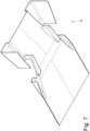
- the rear part of the chassis 76 comprises sidebars 77 which are arranged at the spherical tanks 15 to protect the spherical tanks 15 from lateral impacts; the sidebars 77 form tetrahedrons to have greater impact resistance.
- an engine compartment 78 is obtained inside the chassis 76, wherein the internal combustion engine 5 is arranged.
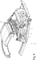
- the bottom 14 of the car 1 comprises an opening 79 which is arranged at the engine compartment 78 and a removable panel 80 which is removably fixed and closes the opening 79.
- the opening 79 has a dimension similar to the dimension of the engine compartment 78; i.e., the dimension of the opening 79 is approximately (as far as possible) equal to the dimension of the engine compartment 78 so that there can be complete access to the engine compartment 78 through the opening 79.
- the removable panel 80 is at least partially transparent; in particular, the removable panel 80 has a transparent window 81 (e.g., glass) in the centre.
- the function of the transparent window 81 is essentially technical in that it allows the internal combustion engine 5 to be visually inspected without having to remove the removable panel 80.
- the body 12 has no opening bonnet (arranged above the engine compartment 78) allowing access to the engine compartment 78; i.e., access to the engine compartment 78 is only from below through the opening 79, as the upper part of the engine compartment 78 is permanently closed by fixed, non-removable panels of the body 12.
- the removable panel 80 is directly fixed to the chassis 76 by means of a plurality of screws 82 (preferably quarter-turn screws 82).
- the rear aerodynamic diffuser 75 faces the road surface 14, is arranged to the rear of the removable panel 80 and borders the removable panel 80. That is, the rear aerodynamic diffuser 75 starts where the removable panel 80 ends.
- the aerodynamic diffuser 75 is also detachable to allow easier access to the containing body 73 of the transmission 7.
- the turbine unit 42 is provided, which generates electrical energy by means of the electric generator 54 and the compressor unit 37 drives the two compressors 49 by means of the electric motor 50, which utilises (at least in part) the electrical energy generated by the electric generator 54 of the turbine unit 42.
- the turbine unit 42 is not provided and the compressor unit 37 lacks the electric motor 50 since the two compressors 49 are driven by the transmission 7, drawing motion from the drum 64 of the clutches 65 of the transmission 7 (as will be further explained below).
- the two compressors 49 are driven by the transmission shaft 67 of the transmission 7 (which directly rotates the drum 64 of the clutches 65 and is directly connected to the drive shaft 20).
- This embodiment is energetically somewhat less efficient (not recovering part of the energy of the exhaust gases through the turbine unit 42) but is lighter, more compact and simpler, eliminating the electrical part altogether (in fact, neither the electric generator 54 of the turbine unit 42 nor the electric motor 50 of the compressor unit 37 are present).
- an actuating system 83 which connects the drum 64 of the transmission 7 to the compressor unit 37 (i.e., to the two compressors 49 of the compressor unit 37) so as to receive motion from the drum 64 of the transmission 7 to bring the two compressors 49 of the compressor unit 37 into rotation.
- the actuating system 83 increases the rotation speed so that the two compressors 49 of the compressor unit 37 always rotate faster than the drum 64 of the transmission 7; for example, the two compressors 49 of the compressor unit 37 could rotate 7-8 times faster than the drum 64 of the transmission 7.
- the actuating system 83 is connected to an end wall of the drum 64 of the transmission 7 on the opposite side of the transmission shaft 67; that is, the drum 64 of the transmission 7 has an end wall which is connected to the transmission shaft 67 on one side and is connected to the actuating system 83 on the opposite side.
- the gear ratio is larger and therefore (for the same rotation speed of the drum 64) the compressors 49 run faster, whereas when the rotation speed of the drum 64 of the transmission 7 is higher, the gear ratio is smaller and therefore (for the same rotation speed of the drum 64) the compressors 49 turn slower; thereby, the compressors 49 are able to generate effective compression even when the drum 64 of the transmission rotates slowly without "over-revving" when the drum 64 of the transmission rotates fast.
- the varying device 84 has only two different gear ratios; by way of example, the two gear ratios obtainable by means of the varying device 84 could differ from each other by 30-40%.
- the varying device 84 is connected to the drum 64 of the transmission 7 on the opposite side of the primary shafts 66 and the transmission shaft 67.
- the compressors 49 rotate much faster than the drive shaft 20 (i.e., the drum 64 of the transmission 7): the compressors 49 rotate about ten times faster than the drive shaft 20 (i.e., the compressors 49 can reach 100,000 rpm while the drive shaft 20 can reach 10,000 rpm).
- each compressor 49 comprises an axial inlet 51 arranged on the opposite side of the actuating system 83 and a radial outlet 52. As described above, there is a joining duct 53 (not illustrated in figures 22-25 ) which is connected to both outlets 52 of the two compressors 49 to receive and join the compressed air from both compressors 49.
- the exhaust system 32 comprises a single exhaust duct 92 which receives exhaust gases from both exhaust ducts 41; i.e., the two exhaust ducts 41 join to converge towards the single exhaust duct 92.
- the exhaust duct 92 starts at the junction of the two exhaust ducts 41 and terminates in the silencer 44.
- the compressor unit 37 comprises two twin compressors 49; according to a different embodiment not illustrated, the compressor unit 37 comprises a single compressor 49.
- the turbine unit 42 (when present) comprises two twin turbines 43; in a different embodiment not illustrated, the turbine unit 42 (when present) comprises a single turbine 43.
- the car 1 as described above has many advantages.
- the car 1 described above allows to simultaneously combines a large hydrogen storage capacity (thus being able to offer a satisfactory range) with very high dynamic performance thanks to an optimal wheelbase, overall weight, and weight distribution. These results are achieved thanks to the particular shape and arrangement of the internal combustion engine 5 and the transmission system 6, which allow to create a large amount of free space to house the hydrogen tanks 9 and 10 without penalising the dynamic performance of the car 1.
- the car 1 as described above allows the construction of an extremely large rear aerodynamic chute (diffuser), thus enabling the generation of a very high aerodynamic load without any penalisation of aerodynamic drag.
- twin compressors 49 are arranged coaxially on opposite sides of the electric motor 50, it is possible to obtain a particularly favourable arrangement of all the elements of the powertrain system (i.e., compact while being very functional); at the same time, the presence of twin compressors 49 allows particularly high air flow rates to be compressed.
- the geometry of the intake ducts 34 and 38 is optimal in terms of both overall dimensions and pressure drop without having to resort to an electric actuation of the compressor unit 37; this result is obtained by drawing the motion necessary to bring the two compressors 49 of the compressor unit 37 into rotation directly from the drum 64 of the dual-clutch transmission 7, which is in a very favourable position for the positioning of the compressor unit 37.
- the particular conformation and positioning of the two intercoolers 39 and 40 allow to maximise the cooling effectiveness and efficiency of the compressed air without requiring overly severe constraints on the placement of all the other components of the internal combustion engine 5.
- the aerodynamic diffuser 75 is very large (thus allowing a high aerodynamic load to be generated with a modest increase in drag) even if the internal combustion engine 5 is located in a central/rear position (thus having an optimal distribution of masses between the front and rear axle) and, at the same time, the wheelbase is relatively short (i.e., the car 1 exhibits extremely high-performance dynamic behaviour).
- This result is obtained by placing the internal combustion engine 5 with the drive shaft 20 arranged higher: thereby, also the transmission 7 can be arranged higher, thus freeing up the necessary space in the lower part of the rear of the car to house the aerodynamic diffuser 75 having a very large size.
- the fact that the removable panel is at least partially transparent constitutes not only an undoubted technical advantage as explained above, but also an aesthetic innovation and makes the removable panel also an aesthetic element; it is important to note that thanks to the large aerodynamic diffuser 75, it is relatively easy to see at least part of the internal combustion engine 5 through the transparent part of the removable panel without having to bend down excessively.
- the body 12 is particularly rigid and strong thanks to the complete absence of an opening for access to the engine compartment 78 (and normally closed by a bonnet). Thereby, with the same rigidity, the overall mass of the body 12 can be reduced. Furthermore, the absence of an opening for access to the engine compartment 78 also makes the body 12 completely continuous (i.e., without interruptions), thus reducing the aerodynamic penetration coefficient.
- the possibility of eliminating an opening for access to the engine compartment 78 through the body 12 is given by the fact that the internal combustion engine 5 does not require any maintenance in the upper part (consisting of the crankcase 17) and consequently it is no longer necessary to access the engine compartment 78 from above. In fact, all the main components of the internal combustion engine 5 are located in the lower part of the engine compartment 78 and are easily accessible from the bottom 14 through the opening 79 closed by the removable panel 80.
- the lubrication pumps 60 and 61 and the cooling pump 63 are optimally placed to minimise the number of components required to bring the pumps 60, 61 and 63 in rotation and, at the same time, keep the pressure drops in the lubrication circuit 59 and the cooling circuit 62 low. That is, the simultaneous grouping and actuation by means of the two camshafts 23 and 26 of the four pumps 60, 61 and 63 makes the solution cheaper, lighter and more compact relative to the known solutions currently on the market.
Landscapes
- Engineering & Computer Science (AREA)
- Chemical & Material Sciences (AREA)
- Combustion & Propulsion (AREA)
- Mechanical Engineering (AREA)
- General Engineering & Computer Science (AREA)
- Transportation (AREA)
- Supercharger (AREA)
- Cooling, Air Intake And Gas Exhaust, And Fuel Tank Arrangements In Propulsion Units (AREA)
- Exhaust Silencers (AREA)
Claims (12)
- Fahrzeug (1), aufweisend:zwei Vorderräder (2);zwei hintere Antriebsräder (4);einen Fahrgastraum (15), der zwischen den zwei Vorderrädern (2) und den zwei Hinterrädern (4) angeordnet ist;eine Karosserie (12), die den Fahrgastraum (15) begrenzt und zwei Seitenwände aufweist, in denen mindestens zwei Türen (13) vorgesehen sind;einem Boden (14), der der unterste Teil des Fahrzeugs (1) ist und im Gebrauch einer Straßenoberfläche zugewandt ist, auf der sich das Fahrzeug (1) bewegt;einen Verbrennungsmotor (5), der in Längsrichtung angeordnet und mit mehreren Zylindern (18) versehen ist, in denen jeweilige Kolben (19) gleiten, und mit einer mit den Kolben (19) verbundenen Antriebswelle (20); undmindestens eine Abgasleitung (41), die von den Zylindern (18) ausgeht und in einem Schalldämpfer (44) endet, der mit mindestens einer Auslassöffnung (46) versehen ist, die asymmetrisch an einer einzelnen Seite des Fahrzeugs (1) angeordnet ist und sich zwischen einem Hinterrad (4) und einer Tür (13) befindet;wobei das Fahrzeug (1) dadurch gekennzeichnet ist, dass:der Verbrennungsmotor (5) in einer zentralen oder hinteren Position hinter dem Fahrgastraum (15) angeordnet ist; undbei dem Verbrennungsmotor (5) die Zylinder (18) in einer Reihe angeordnet sind.
- Fahrzeug (1) nach Anspruch 1, wobei sich die Auslassöffnung (46) des Schalldämpfers (44) auf der Seite angeordnet ist, auf der sich der Fahrerplatz (16) befindet.
- Fahrzeug (1) nach Anspruch 1 oder 2, wobei die Auslassöffnung (46) des Schalldämpfers (44) durch eine Seitenwand der Karosserie (12) hindurch vorgesehen ist.
- Fahrzeug (1) nach Anspruch 1 oder 2, wobei die Auslassöffnung (46) des Schalldämpfers (44) durch den Boden (14) hindurch vorgesehen ist.
- Fahrzeug (1) nach einem der Ansprüche 1 bis 4, wobei der Schalldämpfer (44) eine einzelne Auslassöffnung (46) aufweist.
- Fahrzeug (1) nach einem der Ansprüche 1 bis 5, wobei der Schalldämpfer (44) an einer Seite des Fahrzeugs (1) neben einem Zylinderblock des Verbrennungsmotors (5) und vor einem hinteren Antriebsrad (4) angeordnet ist.
- Fahrzeug (1) nach einem der Ansprüche 1 bis 6, wobei der Verbrennungsmotor (5) zwei Abgasleitungen (41) aufweist, die voneinander unabhängig und getrennt sind, von den Zylindern (18) ausgehen und in den einzelnen gemeinsamen Schalldämpfer (44) münden.
- Fahrzeug (1) nach einem der Ansprüche 1 bis 6,
wobei der Verbrennungsmotor (5) aufweist:zwei erste Abgaskanäle (41), die unabhängig und getrennt voneinander sind und von den Zylindern (18) ausgehen; undeinen zweiten Abgaskanal (92), wobei die zwei ersten Abgaskanäle (41) in diesem zusammenlaufen und der in dem einzelnen gemeinsamen Schalldämpfer (44) endet. - Fahrzeug (1) nach Anspruch 8 mit zwei Abgasbehandlungsvorrichtungen (33), die jeweils entlang eines jeweiligen ersten Abgaskanals (41) angeordnet sind.
- Fahrzeug (1) nach einem der Ansprüche 1 bis 9 und einen einzelnen Schalldämpfer (44) aufweisend, der mit der Auslassöffnung (46) versehen ist.
- Fahrzeug (1) nach Anspruch 10, wobei der einzelne Schalldämpfer (44) asymmetrisch entlang eines Zylinderblocks des Verbrennungsmotors (5) angeordnet ist.
- Fahrzeug (1) nach Anspruch 11, wobei der einzelne Schalldämpfer (44) zwischen dem Zylinderblock des Verbrennungsmotors (5) und einer Seitenwand des Fahrzeugs (1) angeordnet ist.
Applications Claiming Priority (1)
| Application Number | Priority Date | Filing Date | Title |
|---|---|---|---|
| IT202200017568 | 2022-08-25 |
Publications (2)
| Publication Number | Publication Date |
|---|---|
| EP4328428A1 EP4328428A1 (de) | 2024-02-28 |
| EP4328428B1 true EP4328428B1 (de) | 2025-06-11 |
Family
ID=84053017
Family Applications (1)
| Application Number | Title | Priority Date | Filing Date |
|---|---|---|---|
| EP23192866.4A Active EP4328428B1 (de) | 2022-08-25 | 2023-08-23 | Kraftfahrzeug mit einem verbrennungsmotor aufweisend eine seitliche abgasauslassöffnung |
Country Status (4)
| Country | Link |
|---|---|
| US (1) | US12491762B2 (de) |
| EP (1) | EP4328428B1 (de) |
| JP (1) | JP2024037689A (de) |
| CN (1) | CN117621808A (de) |
Family Cites Families (7)
| Publication number | Priority date | Publication date | Assignee | Title |
|---|---|---|---|---|
| DE10042012B4 (de) | 1999-11-22 | 2004-08-19 | Daimlerchrysler Ag | Vorrichtung zur Geräuschgestaltung bei einem Kraftfahrzeug |
| EP1980437B1 (de) * | 2007-04-13 | 2011-12-21 | Mazda Motor Corporation | Vorderaufbau eines Fahrzeugs |
| JP4993755B2 (ja) | 2008-03-18 | 2012-08-08 | 日産自動車株式会社 | 吸気音発生装置 |
| US8127888B1 (en) | 2011-02-02 | 2012-03-06 | Mann + Hummel, GmbH | Engine sound distribution apparatus for a motor vehicle |
| DE102012109668A1 (de) | 2012-10-11 | 2014-04-17 | Dr. Ing. H.C. F. Porsche Aktiengesellschaft | Vorrichtung zur Geräuschübertragung bei einem Kraftfahrzeug |
| IT201900006696A1 (it) * | 2019-05-09 | 2020-11-09 | Ferrari Spa | Veicolo ibrido a quattro ruote motrici comprendente un motore termico a combustione interna provvisto di una turbina elettrificata e corrispondente metodo di controllo |
| US11713700B2 (en) * | 2020-07-24 | 2023-08-01 | Mike's Pipes, Inc. | Method and apparatus for converting a vehicle from a dual-in, single-out exhaust system to a dual-in, dual-out exhaust system |
-
2023
- 2023-08-23 EP EP23192866.4A patent/EP4328428B1/de active Active
- 2023-08-23 JP JP2023135270A patent/JP2024037689A/ja active Pending
- 2023-08-24 CN CN202311075970.3A patent/CN117621808A/zh active Pending
- 2023-08-24 US US18/454,878 patent/US12491762B2/en active Active
Also Published As
| Publication number | Publication date |
|---|---|
| EP4328428A1 (de) | 2024-02-28 |
| US20240100938A1 (en) | 2024-03-28 |
| CN117621808A (zh) | 2024-03-01 |
| JP2024037689A (ja) | 2024-03-19 |
| US12491762B2 (en) | 2025-12-09 |
Similar Documents
| Publication | Publication Date | Title |
|---|---|---|
| EP4328418B1 (de) | Turbinenanordnung für einen verbrennungsmotor | |
| EP4328121B1 (de) | Kraftfahrzeug mit einer brennkraftmaschine und mit einem doppelkupplungsgetriebe | |
| EP4328426B1 (de) | Kraftfahrzeug mit einem verbrennungsmotor, dessen pumpen durch nockenwellen angetrieben werden | |
| EP4328432B1 (de) | Fahrzeug mit einem verbrennungsmotor mit einer obenliegenden antriebswelle | |
| EP4328428B1 (de) | Kraftfahrzeug mit einem verbrennungsmotor aufweisend eine seitliche abgasauslassöffnung | |
| US12234764B2 (en) | Car provided with a supercharged internal combustion engine | |
| EP4328059B1 (de) | Fahrzeug mit wasserstoffbetriebenem verbrennungsmotor | |
| EP4375480B1 (de) | Fahrzeug mit verbrennungsmotor | |
| US12617264B2 (en) | Car provided with an internal combustion engine arranged with the drive shaft up | |
| US12491945B2 (en) | Car provided with an internal combustion engine | |
| EP4328430B1 (de) | Auto-provider mit aufgeladenem verbrennungsmotor mit ladeluftkühler | |
| CN117621796A (zh) | 具有布置成驱动轴在上面的内燃机的汽车 |
Legal Events
| Date | Code | Title | Description |
|---|---|---|---|
| PUAI | Public reference made under article 153(3) epc to a published international application that has entered the european phase |
Free format text: ORIGINAL CODE: 0009012 |
|
| STAA | Information on the status of an ep patent application or granted ep patent |
Free format text: STATUS: THE APPLICATION HAS BEEN PUBLISHED |
|
| AK | Designated contracting states |
Kind code of ref document: A1 Designated state(s): AL AT BE BG CH CY CZ DE DK EE ES FI FR GB GR HR HU IE IS IT LI LT LU LV MC ME MK MT NL NO PL PT RO RS SE SI SK SM TR |
|
| STAA | Information on the status of an ep patent application or granted ep patent |
Free format text: STATUS: REQUEST FOR EXAMINATION WAS MADE |
|
| 17P | Request for examination filed |
Effective date: 20240314 |
|
| RBV | Designated contracting states (corrected) |
Designated state(s): AL AT BE BG CH CY CZ DE DK EE ES FI FR GB GR HR HU IE IS IT LI LT LU LV MC ME MK MT NL NO PL PT RO RS SE SI SK SM TR |
|
| RIC1 | Information provided on ipc code assigned before grant |
Ipc: F01N 13/18 20100101AFI20241125BHEP |
|
| GRAP | Despatch of communication of intention to grant a patent |
Free format text: ORIGINAL CODE: EPIDOSNIGR1 |
|
| STAA | Information on the status of an ep patent application or granted ep patent |
Free format text: STATUS: GRANT OF PATENT IS INTENDED |
|
| INTG | Intention to grant announced |
Effective date: 20250107 |
|
| GRAS | Grant fee paid |
Free format text: ORIGINAL CODE: EPIDOSNIGR3 |
|
| GRAA | (expected) grant |
Free format text: ORIGINAL CODE: 0009210 |
|
| STAA | Information on the status of an ep patent application or granted ep patent |
Free format text: STATUS: THE PATENT HAS BEEN GRANTED |
|
| AK | Designated contracting states |
Kind code of ref document: B1 Designated state(s): AL AT BE BG CH CY CZ DE DK EE ES FI FR GB GR HR HU IE IS IT LI LT LU LV MC ME MK MT NL NO PL PT RO RS SE SI SK SM TR |
|
| REG | Reference to a national code |
Ref country code: GB Ref legal event code: FG4D |
|
| REG | Reference to a national code |
Ref country code: CH Ref legal event code: EP |
|
| REG | Reference to a national code |
Ref country code: DE Ref legal event code: R096 Ref document number: 602023003924 Country of ref document: DE |
|
| REG | Reference to a national code |
Ref country code: IE Ref legal event code: FG4D |
|
| PG25 | Lapsed in a contracting state [announced via postgrant information from national office to epo] |
Ref country code: ES Free format text: LAPSE BECAUSE OF FAILURE TO SUBMIT A TRANSLATION OF THE DESCRIPTION OR TO PAY THE FEE WITHIN THE PRESCRIBED TIME-LIMIT Effective date: 20250611 Ref country code: FI Free format text: LAPSE BECAUSE OF FAILURE TO SUBMIT A TRANSLATION OF THE DESCRIPTION OR TO PAY THE FEE WITHIN THE PRESCRIBED TIME-LIMIT Effective date: 20250611 |
|
| PGFP | Annual fee paid to national office [announced via postgrant information from national office to epo] |
Ref country code: DE Payment date: 20250827 Year of fee payment: 3 |
|
| REG | Reference to a national code |
Ref country code: LT Ref legal event code: MG9D |
|
| PG25 | Lapsed in a contracting state [announced via postgrant information from national office to epo] |
Ref country code: GR Free format text: LAPSE BECAUSE OF FAILURE TO SUBMIT A TRANSLATION OF THE DESCRIPTION OR TO PAY THE FEE WITHIN THE PRESCRIBED TIME-LIMIT Effective date: 20250912 Ref country code: NO Free format text: LAPSE BECAUSE OF FAILURE TO SUBMIT A TRANSLATION OF THE DESCRIPTION OR TO PAY THE FEE WITHIN THE PRESCRIBED TIME-LIMIT Effective date: 20250911 |
|
| PGFP | Annual fee paid to national office [announced via postgrant information from national office to epo] |
Ref country code: IT Payment date: 20250901 Year of fee payment: 3 |
|
| REG | Reference to a national code |
Ref country code: NL Ref legal event code: MP Effective date: 20250611 |
|
| PG25 | Lapsed in a contracting state [announced via postgrant information from national office to epo] |
Ref country code: BG Free format text: LAPSE BECAUSE OF FAILURE TO SUBMIT A TRANSLATION OF THE DESCRIPTION OR TO PAY THE FEE WITHIN THE PRESCRIBED TIME-LIMIT Effective date: 20250611 |
|
| PG25 | Lapsed in a contracting state [announced via postgrant information from national office to epo] |
Ref country code: HR Free format text: LAPSE BECAUSE OF FAILURE TO SUBMIT A TRANSLATION OF THE DESCRIPTION OR TO PAY THE FEE WITHIN THE PRESCRIBED TIME-LIMIT Effective date: 20250611 |
|
| PGFP | Annual fee paid to national office [announced via postgrant information from national office to epo] |
Ref country code: FR Payment date: 20250825 Year of fee payment: 3 Ref country code: AT Payment date: 20251020 Year of fee payment: 3 |
|
| PG25 | Lapsed in a contracting state [announced via postgrant information from national office to epo] |
Ref country code: RS Free format text: LAPSE BECAUSE OF FAILURE TO SUBMIT A TRANSLATION OF THE DESCRIPTION OR TO PAY THE FEE WITHIN THE PRESCRIBED TIME-LIMIT Effective date: 20250911 |
|
| PG25 | Lapsed in a contracting state [announced via postgrant information from national office to epo] |
Ref country code: LV Free format text: LAPSE BECAUSE OF FAILURE TO SUBMIT A TRANSLATION OF THE DESCRIPTION OR TO PAY THE FEE WITHIN THE PRESCRIBED TIME-LIMIT Effective date: 20250611 |
|
| PG25 | Lapsed in a contracting state [announced via postgrant information from national office to epo] |
Ref country code: NL Free format text: LAPSE BECAUSE OF FAILURE TO SUBMIT A TRANSLATION OF THE DESCRIPTION OR TO PAY THE FEE WITHIN THE PRESCRIBED TIME-LIMIT Effective date: 20250611 |
|
| PG25 | Lapsed in a contracting state [announced via postgrant information from national office to epo] |
Ref country code: PT Free format text: LAPSE BECAUSE OF FAILURE TO SUBMIT A TRANSLATION OF THE DESCRIPTION OR TO PAY THE FEE WITHIN THE PRESCRIBED TIME-LIMIT Effective date: 20251013 |
|
| REG | Reference to a national code |
Ref country code: AT Ref legal event code: MK05 Ref document number: 1802427 Country of ref document: AT Kind code of ref document: T Effective date: 20250611 |
|
| PG25 | Lapsed in a contracting state [announced via postgrant information from national office to epo] |
Ref country code: IS Free format text: LAPSE BECAUSE OF FAILURE TO SUBMIT A TRANSLATION OF THE DESCRIPTION OR TO PAY THE FEE WITHIN THE PRESCRIBED TIME-LIMIT Effective date: 20251011 |
|
| PG25 | Lapsed in a contracting state [announced via postgrant information from national office to epo] |
Ref country code: SM Free format text: LAPSE BECAUSE OF FAILURE TO SUBMIT A TRANSLATION OF THE DESCRIPTION OR TO PAY THE FEE WITHIN THE PRESCRIBED TIME-LIMIT Effective date: 20250611 Ref country code: AT Free format text: LAPSE BECAUSE OF FAILURE TO SUBMIT A TRANSLATION OF THE DESCRIPTION OR TO PAY THE FEE WITHIN THE PRESCRIBED TIME-LIMIT Effective date: 20250611 |
|
| PG25 | Lapsed in a contracting state [announced via postgrant information from national office to epo] |
Ref country code: CZ Free format text: LAPSE BECAUSE OF FAILURE TO SUBMIT A TRANSLATION OF THE DESCRIPTION OR TO PAY THE FEE WITHIN THE PRESCRIBED TIME-LIMIT Effective date: 20250611 |
|
| PG25 | Lapsed in a contracting state [announced via postgrant information from national office to epo] |
Ref country code: PL Free format text: LAPSE BECAUSE OF FAILURE TO SUBMIT A TRANSLATION OF THE DESCRIPTION OR TO PAY THE FEE WITHIN THE PRESCRIBED TIME-LIMIT Effective date: 20250611 |
|
| PG25 | Lapsed in a contracting state [announced via postgrant information from national office to epo] |
Ref country code: EE Free format text: LAPSE BECAUSE OF FAILURE TO SUBMIT A TRANSLATION OF THE DESCRIPTION OR TO PAY THE FEE WITHIN THE PRESCRIBED TIME-LIMIT Effective date: 20250611 |
|
| PG25 | Lapsed in a contracting state [announced via postgrant information from national office to epo] |
Ref country code: SK Free format text: LAPSE BECAUSE OF FAILURE TO SUBMIT A TRANSLATION OF THE DESCRIPTION OR TO PAY THE FEE WITHIN THE PRESCRIBED TIME-LIMIT Effective date: 20250611 |
|
| PG25 | Lapsed in a contracting state [announced via postgrant information from national office to epo] |
Ref country code: RO Free format text: LAPSE BECAUSE OF FAILURE TO SUBMIT A TRANSLATION OF THE DESCRIPTION OR TO PAY THE FEE WITHIN THE PRESCRIBED TIME-LIMIT Effective date: 20250611 |
|
| REG | Reference to a national code |
Ref country code: DE Ref legal event code: R097 Ref document number: 602023003924 Country of ref document: DE |
|
| PG25 | Lapsed in a contracting state [announced via postgrant information from national office to epo] |
Ref country code: MC Free format text: LAPSE BECAUSE OF FAILURE TO SUBMIT A TRANSLATION OF THE DESCRIPTION OR TO PAY THE FEE WITHIN THE PRESCRIBED TIME-LIMIT Effective date: 20250611 |
|
| PG25 | Lapsed in a contracting state [announced via postgrant information from national office to epo] |
Ref country code: DK Free format text: LAPSE BECAUSE OF FAILURE TO SUBMIT A TRANSLATION OF THE DESCRIPTION OR TO PAY THE FEE WITHIN THE PRESCRIBED TIME-LIMIT Effective date: 20250611 |
|
| PG25 | Lapsed in a contracting state [announced via postgrant information from national office to epo] |
Ref country code: LU Free format text: LAPSE BECAUSE OF NON-PAYMENT OF DUE FEES Effective date: 20250823 |
|
| PLBE | No opposition filed within time limit |
Free format text: ORIGINAL CODE: 0009261 |
|
| STAA | Information on the status of an ep patent application or granted ep patent |
Free format text: STATUS: NO OPPOSITION FILED WITHIN TIME LIMIT |
|
| REG | Reference to a national code |
Ref country code: CH Ref legal event code: L10 Free format text: ST27 STATUS EVENT CODE: U-0-0-L10-L00 (AS PROVIDED BY THE NATIONAL OFFICE) Effective date: 20260423 |