EP4328436A1 - Restriction proportionnelle d'une buse de carburant avec un circuit auxiliaire - Google Patents
Restriction proportionnelle d'une buse de carburant avec un circuit auxiliaire Download PDFInfo
- Publication number
- EP4328436A1 EP4328436A1 EP23193568.5A EP23193568A EP4328436A1 EP 4328436 A1 EP4328436 A1 EP 4328436A1 EP 23193568 A EP23193568 A EP 23193568A EP 4328436 A1 EP4328436 A1 EP 4328436A1
- Authority
- EP
- European Patent Office
- Prior art keywords
- fuel
- valve
- circuit
- auxiliary
- injector
- Prior art date
- Legal status (The legal status is an assumption and is not a legal conclusion. Google has not performed a legal analysis and makes no representation as to the accuracy of the status listed.)
- Pending
Links
Images



Classifications
-
- F—MECHANICAL ENGINEERING; LIGHTING; HEATING; WEAPONS; BLASTING
- F02—COMBUSTION ENGINES; HOT-GAS OR COMBUSTION-PRODUCT ENGINE PLANTS
- F02C—GAS-TURBINE PLANTS; AIR INTAKES FOR JET-PROPULSION PLANTS; CONTROLLING FUEL SUPPLY IN AIR-BREATHING JET-PROPULSION PLANTS
- F02C7/00—Features, components parts, details or accessories, not provided for in, or of interest apart form groups F02C1/00 - F02C6/00; Air intakes for jet-propulsion plants
- F02C7/22—Fuel supply systems
- F02C7/232—Fuel valves; Draining valves or systems
-
- F—MECHANICAL ENGINEERING; LIGHTING; HEATING; WEAPONS; BLASTING
- F02—COMBUSTION ENGINES; HOT-GAS OR COMBUSTION-PRODUCT ENGINE PLANTS
- F02C—GAS-TURBINE PLANTS; AIR INTAKES FOR JET-PROPULSION PLANTS; CONTROLLING FUEL SUPPLY IN AIR-BREATHING JET-PROPULSION PLANTS
- F02C7/00—Features, components parts, details or accessories, not provided for in, or of interest apart form groups F02C1/00 - F02C6/00; Air intakes for jet-propulsion plants
- F02C7/22—Fuel supply systems
- F02C7/222—Fuel flow conduits, e.g. manifolds
-
- F—MECHANICAL ENGINEERING; LIGHTING; HEATING; WEAPONS; BLASTING
- F02—COMBUSTION ENGINES; HOT-GAS OR COMBUSTION-PRODUCT ENGINE PLANTS
- F02C—GAS-TURBINE PLANTS; AIR INTAKES FOR JET-PROPULSION PLANTS; CONTROLLING FUEL SUPPLY IN AIR-BREATHING JET-PROPULSION PLANTS
- F02C9/00—Controlling gas-turbine plants; Controlling fuel supply in air- breathing jet-propulsion plants
- F02C9/26—Control of fuel supply
- F02C9/263—Control of fuel supply by means of fuel metering valves
-
- F—MECHANICAL ENGINEERING; LIGHTING; HEATING; WEAPONS; BLASTING
- F02—COMBUSTION ENGINES; HOT-GAS OR COMBUSTION-PRODUCT ENGINE PLANTS
- F02C—GAS-TURBINE PLANTS; AIR INTAKES FOR JET-PROPULSION PLANTS; CONTROLLING FUEL SUPPLY IN AIR-BREATHING JET-PROPULSION PLANTS
- F02C9/00—Controlling gas-turbine plants; Controlling fuel supply in air- breathing jet-propulsion plants
- F02C9/26—Control of fuel supply
- F02C9/32—Control of fuel supply characterised by throttling of fuel
- F02C9/34—Joint control of separate flows to main and auxiliary burners
-
- F—MECHANICAL ENGINEERING; LIGHTING; HEATING; WEAPONS; BLASTING
- F23—COMBUSTION APPARATUS; COMBUSTION PROCESSES
- F23R—GENERATING COMBUSTION PRODUCTS OF HIGH PRESSURE OR HIGH VELOCITY, e.g. GAS-TURBINE COMBUSTION CHAMBERS
- F23R3/00—Continuous combustion chambers using liquid or gaseous fuel
- F23R3/28—Continuous combustion chambers using liquid or gaseous fuel characterised by the fuel supply
-
- F—MECHANICAL ENGINEERING; LIGHTING; HEATING; WEAPONS; BLASTING
- F05—INDEXING SCHEMES RELATING TO ENGINES OR PUMPS IN VARIOUS SUBCLASSES OF CLASSES F01-F04
- F05D—INDEXING SCHEME FOR ASPECTS RELATING TO NON-POSITIVE-DISPLACEMENT MACHINES OR ENGINES, GAS-TURBINES OR JET-PROPULSION PLANTS
- F05D2270/00—Control
- F05D2270/30—Control parameters, e.g. input parameters
- F05D2270/31—Fuel schedule for stage combustors
-
- F—MECHANICAL ENGINEERING; LIGHTING; HEATING; WEAPONS; BLASTING
- F05—INDEXING SCHEMES RELATING TO ENGINES OR PUMPS IN VARIOUS SUBCLASSES OF CLASSES F01-F04
- F05D—INDEXING SCHEME FOR ASPECTS RELATING TO NON-POSITIVE-DISPLACEMENT MACHINES OR ENGINES, GAS-TURBINES OR JET-PROPULSION PLANTS
- F05D2270/00—Control
- F05D2270/60—Control system actuates means
- F05D2270/62—Electrical actuators
Definitions
- the present invention relates to fuel control and delivery systems of turbine engines, particularly to fuel injectors and nozzles, such as those found in commercial aircraft.
- Turbine fuel control systems such as those typically found in commercial aircraft include various robust controls to allow for optimized operational characteristics under different load conditions.
- a mechanical fuel metering or “scheduling" valve is provided in connection with a fuel injector and serves to respond to an increase in fuel pressure supplied to it by gradually opening one or more flow paths, such as to a primary and/or secondary fuel injector nozzle.
- a resistive spring provides the force balance to limit the rate at which the scheduling valve opens.
- Gas turbine combustors will typically have a natural frequency that may become excited when a certain heat release is attained. Quite often this phenomenon occurs at ground conditions, however, it can also be a concern under multiple flow conditions. This condition can cause significant levels of noise and occasionally may negatively impact the health of the structural components within and around the combustor. To mitigate this noise, adjustments to fuel scheduling may be directed, in an attempt to decouple the heat release and noise, however, these attempts require additional flow dividing hardware and fuel manifolds, adding significant cost, weight, and power requirements.
- a fuel injector for a turbine engine includes a housing having an internal enclosure for pressurized fluid, a fuel inlet formed on the housing, permitting delivery of a fuel supply to the fuel injector, a scheduling valve disposed within the housing, configured for regulation of fuel flow from the fuel inlet in response to fuel pressure received at the fuel inlet, a primary fuel circuit formed in the housing, receiving fuel from the scheduling valve, a secondary fuel circuit formed in the housing, receiving fuel from the scheduling valve, an auxiliary fuel circuit formed in the housing, receiving fuel from the scheduling valve, an electrically-controlled valve in fluid communication with the auxiliary fuel circuit, adapted and configured to actively control fuel through the auxiliary fuel circuit in response to a control signal, a fuel nozzle in fluid communication with and receiving fuel from the primary, secondary and auxiliary fuel circuits, a primary outlet formed on the nozzle, in fluid communication with the primary fuel circuit, a secondary outlet formed on the nozzle, in fluid communication with the secondary fuel circuit, and an auxiliary outlet formed on the nozzle, in
- the electrically-controlled valve can be a discrete open/closed valve. It is also contemplated that the electrically-controlled valve can be a proportional valve with intermediate conditions between fully open and fully closed.
- the proportional valve can include a proportional solenoid, a stepper motor, or a torque motor based servo valve with flapper and nozzle.
- the scheduling valve can include a valve spool, biased to a closed position by one or more biasing members, wherein the valve spool is configured to regulate flow from the inlet of the injector to each of the primary and secondary circuits, and wherein the valve spool includes a scheduling surface configured to vary flow area through the secondary circuit based on position of the valve spool within the scheduling valve.
- the valve spool can additionally be configured to regulate flow from the inlet of the injector to the auxiliary fuel circuit.
- the auxiliary fuel circuit can branch off of the primary fuel circuit.
- the auxiliary fuel circuit can be an independent fuel circuit downstream from the valve spool.
- activation of the electrically-controlled valve can control fuel flow rate through the auxiliary fuel circuit.
- the electrically-controlled valve can be a binary valve.
- the electrically-controlled valve can be a modulating valve.
- the electrically-controlled valve can be a motorized valve.
- a fuel supply system for a turbine engine includes a single fuel manifold adapted to receive and distribute a fuel supply to a plurality of points of the turbine engine, and a plurality of fuel injectors distributed around a periphery of the engine, adapted and configured to receive fuel from the single fuel manifold.
- At least one of the fuel injectors has a housing having an internal enclosure for pressurized fluid, a fuel inlet formed on the housing, permitting delivery of fuel supply from the single fuel manifold to the fuel injector, a scheduling valve disposed within the housing, configured for regulation of fuel flow from the fuel inlet in response to fuel pressure received at the fuel inlet, a primary fuel circuit formed in the housing, receiving fuel from the scheduling valve, a secondary fuel circuit formed in the housing, receiving fuel from the scheduling valve, an auxiliary fuel circuit formed in the housing, receiving fuel from the scheduling valve, an electrically-controlled valve in fluid communication with the auxiliary fuel circuit adapted and configured to actively control fuel through the auxiliary fuel circuit in response to a control signal, a fuel nozzle in fluid communication with and receiving fuel from the primary, secondary and auxiliary fuel circuits, a primary outlet formed on the nozzle, in fluid communication with the primary fuel circuit, a secondary outlet formed on the nozzle, in fluid communication with the secondary fuel circuit, and an auxiliary outlet formed on the nozzle, in fluid communication
- the electrically-controlled valve can be a discrete open/closed valve. It is also contemplated that the electrically-controlled valve can be a proportional valve with intermediate conditions between fully open and fully closed.
- the proportional valve can include a proportional solenoid or a stepper motor.
- the system can further include at least one passive fuel injector, receiving fuel from the single fuel manifold.
- the at least one passive fuel injector can include only one nozzle. If desired, the at least one passive fuel injector can be a duplex injector.
- a metering valve can be provided, and adapted and configured to receive a fuel supply from a fuel pump, and output the fuel to the single manifold.
- the fuel supply system can further include a check valve arranged in a fuel supply line between a fuel pump and the single manifold.
- a controller can be provided in connection with the system, and electrically connected to the electrically-controlled valve on at least one fuel injector for individual control thereof.
- a controller can be provided in connection with the system, and electrically connected to each of the electrically-controlled valves on a plurality of fuel injectors for ganged control thereof.
- Each of the injectors in the plurality of fuel injectors can include a mass flow sensor operatively connected to the controller to provide mass flow feedback to the controller.
- FIG. 1 there is illustrated a schematic cross-sectional perspective view of a valve arrangement 100 for a fuel injector in accordance with one aspect of the present invention.
- the valve 100 includes a housing 110, a fuel inlet 115, and a movable valve member or spool 111, which is fitted inside the housing 110, and resiliently urged into a normally closed position, unless acted on by sufficient inlet fuel pressure to overcome the biasing force(s).
- the spool 111 When experiencing increased fuel pressure of a predetermined value, the spool 111 is urged downward, allowing fuel to pass into a primary outlet chamber 113. Fuel is thus supplied to a primary fuel circuit 117. In the illustrated embodiment, fuel is also supplied to an auxiliary fuel circuit 118 leading from the primary outlet chamber.
- An electrically-controlled valve 120 is provided in the auxiliary fuel circuit 118, with a first portion 118a thereof leading from the primary fuel outlet chamber 113 to the electrically-controlled valve 120, and a second portion 118b leading from the electrically-controlled valve 120 and toward an auxiliary fuel nozzle.
- the electrically-controlled valve 120 enables active adjustment of fuel flowing through the auxiliary fuel circuit 118.
- the electrically-controlled valve 120 can be formed integrally with the housing 110, or formed separately, attached thereto.
- the spool 111 is urged further downward, opening a path for fuel to enter a secondary fuel outlet chamber 119, and thus also a secondary fuel circuit 119.
- Primary fuel circuit 117 and secondary fuel circuit 119 continue to deliver fuel to respective primary and secondary fuel nozzles of an associated fuel injector, while the auxiliary fuel circuit 118 delivers fuel at the command of the electrically-controlled valve 120.
- the same valve arrangement 100 can be used in conjunction with multiple injectors simultaneously.
- valve arrangement 100 including electrically-controlled valve 120 on the auxiliary fuel circuit, permits active control of fuel flow rate through the auxiliary fuel circuit 118, in addition to the regular fuel pressure-based flow schedule determined by the purely mechanical components of the valve 100.
- control may be desirable in order to change the characteristics of the fuel being injected into the combustor of the turbine engine in order to control acoustics, emissions, or mitigate the potential for flame-out, for example.
- the electrically-controlled valve 120 can be of any suitable type, as may be dictated by the desired implementation. Suitable valves can be of solenoid-operated type, or those utilizing electroactive (e.g. piezoelectric) materials, such as those described by U.S. Patent Publication No. 2016/0230904 to Zarrabi et al ., which is incorporated herein by reference, in its entirety. Alternatively, proportional or modulating operators can be utilized, such as by use of a stepper-motor actuator, as well as 3-way solenoid valves or magnetorestrictive valves.
- electroactive e.g. piezoelectric
- a fuel supply system 200 which includes a plurality of triplex injectors 250, each with a valve arrangement 100 as shown in Fig. 1 .
- Each triplex injector 250 includes a primary nozzle 253, a secondary nozzle 255, and an auxiliary nozzle 254 respectively fed by primary 117, secondary 119 and auxiliary 118 fuel circuits of the injector, as described above.
- a plurality of simplex fuel injectors 240 configured so as to act as secondary nozzles, passively - that is, to become active with other secondary nozzles 255 of the system 200 in response to increased fuel pressure above a predetermined level.
- the triplex 250 and simplex 240 injectors are connected by way of a single fuel manifold 260, which receives fuel via inlet 263, optionally from a common fuel metering valve.
- a single fuel manifold 260 which receives fuel via inlet 263, optionally from a common fuel metering valve.
- different combinations of valve types can be combined, such as duplex injectors in place of simplex injectors 240.
- duplex injectors can be of a purely passive design, as discussed above, depending on the desired implementation.
- a controller 290 is also illustrated interfacing with respective valves 100, in order to actively adjust fuel flow, as described above.
- electrical connections are only illustrated for a portion of the triplex injectors 250 having electrically-controlled valves 120.
- the controller can be configured so as to enable individual control of each electrically-controlled valve 120, or alternatively, can be configured so as to control them in predetermined groupings or in "ganged" fashion.
- a first sub-set of triplex injectors 257a is grouped circumferentially offset from the second sub-set of triplex injectors 257b.
- this circumferential arrangement can be modified as needed for a given engine application, and that control of the injectors 240, 250 as described herein allows for finely tuned control of the flame in an associated combustor.
- control of electrically-controlled valves 120 can be based on sensor feedback from one or more sensors in the system 200, such as mass flow sensors, pressure sensors and/or valve position sensors, which can allow for health monitoring and active flow control.
- the controller 290 can control certain valves to have higher flow rates than others. That is, if one valve 120 is set to reduce flow, other valves 120 can be set to increase flow to compensate.
- active balancing can prove effective in the dynamics of a turbine combustion chamber.
- the valves can be actuated gradually and/or sequentially to minimize sudden pressure fluctuations within the fuel system 200.
- FIG. 3 is a schematic diagram of the valve arrangement of Fig. 1 , illustrating the functional arrangement of components of the valve 100 and its associated fuel injector 250. Illustrated is the fuel inlet 115, followed by a check function, accomplished by a first open position of the valve spool 111 of Figure 1 . After that, fuel is divided into primary 117, secondary 119 and auxiliary 118 fuel circuits.
- the primary fuel circuit 117 leads directly to the primary nozzle 253 of the fuel injector 250.
- the secondary fuel circuit 119 leads through the fuel scheduling function accomplished also by the valve spool 111, and to the secondary nozzle 255 of the fuel injector 250.
- the auxiliary fuel circuit 118 leads through the electrically-controlled valve 120 and to the auxiliary nozzle 254 of the fuel injector 250.
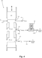
- valve 400 for a fuel injector in accordance with an additional aspect of the present invention.
- the function of the valve 400 is similar to that of valve 100 of Figure 1 , but where the auxiliary fuel circuit 418 is additionally mechanically controlled by the configuration of the valve spool 411.
- the valve 400 includes a housing (not illustrated), a fuel inlet 415, and a movable valve member or spool 411, which is fitted inside the housing, and resiliently urged into a normally closed position, unless acted on by sufficient inlet fuel pressure to overcome the biasing force(s).
- the spool 411 When experiencing increased fuel pressure of a predetermined value, the spool 411 is urged downward, allowing fuel to pass into a primary outlet chamber 413. Fuel is thus supplied to a primary fuel circuit 417.
- auxiliary fuel circuit 418 leading from an auxiliary outlet chamber 412 at a prescribed range in the position of the spool 411, which can be selected as required by the precise implementation.
- the spool 411 is urged further downward, opening a path for fuel to enter a secondary fuel outlet chamber 414, and thus also a secondary fuel circuit 419.
- the primary fuel circuit 417 and secondary fuel circuit 419 continue to deliver fuel to respective primary and secondary fuel nozzles of an associated fuel injector, while the auxiliary fuel circuit 418 delivers fuel at the command of the electrically-controlled valve 120.
- the electrically-controlled valve 120 is provided in the auxiliary fuel circuit 418, with a first portion 418a thereof leading from the auxiliary outlet chamber 412 to the electrically-controlled valve 120, and a second portion 418b leading from the electrically-controlled valve 120 and toward an auxiliary fuel nozzle.
- the electrically-controlled valve 120 enables active adjustment of fuel flowing through the auxiliary fuel circuit 417.
- the electrically-controlled valve 120 can be formed integrally with a housing of the valve 400 or separately attached thereto.
- valve arrangement 400 can be used in conjunction with multiple injectors simultaneously. That is, instead of providing a valve arrangement 400 on each individual injectors, it may be advantageous, depending on the implementation, to distribute the fuel from each of the primary 417, secondary 419 and auxiliary 418 fuel channels to groups of multiple fuel injectors and their respective nozzles.
- valve arrangement 400 including electrically-controlled valve 120 on the auxiliary fuel circuit 418, permits active control of fuel flow rate through the auxiliary fuel circuit 418, in addition to the regular fuel pressure-based flow schedule determined by the purely mechanical components of the valve 100.
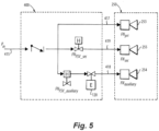
- FIG 5 is a schematic diagram of the valve arrangement 400 of Figure 4 , illustrating the functional arrangement of components of the valve 400 and its associated fuel injector 250. Illustrated is the fuel inlet 415, followed by a check function, accomplished by the positon of the valve spool 411 of Figure 4 . After that, fuel is divided into primary 417, secondary 419 and auxiliary 418 fuel circuits.
- the primary fuel circuit 417 leads directly to the primary nozzle 253 of the fuel injector 250.
- the secondary fuel circuit 419 leads through the fuel scheduling function accomplished also by the valve spool 411, and to the secondary nozzle 255 of the fuel injector 250.
- the auxiliary fuel circuit 418 leads also through a fuel scheduling function accomplished by the valve spool 411, and then through the electrically-controlled valve 120 and to the auxiliary nozzle 254 of the fuel injector 250.
- the fuel schedule for the auxiliary fuel circuit 418 as dictated by the configuration of the spool 411 can be selected as desired. That is, the fuel schedule for the auxiliary fuel circuit 418 can be largely binary, leaving any modulation or gradual control to the electrically-controlled valve 120, which then can be either binary (e.g., solenoid-type), or a more precisely controlled type of electrically-operated valve (e.g., with a stepper motor actuator). Alternatively, the fuel schedule for the auxiliary fuel circuit 418 can be gradually opening, as dictated by the shape of the spool 411, depending on the desired operational characteristics and/or system limitations.
- the electrically-controlled valve 120 is a discrete open/closed valve even if a modulating type valve is used, however it is also contemplated that it can instead be a proportional valve 220, with intermediate conditions between fully open and fully closed.
- the proportional valve 220 includes a proportional solenoid, a stepper motor, or a torque motor based servo valve with flapper and nozzle.
- a stepper motor is used, multiple discrete steps can be used between fully open and fully closed.
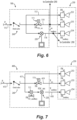
- the check valve 260 is upstream of the branch between the primary, secondary, and auxiliary circuits 117, 118 and 119, and a hydraulic valve, i.e. incorporating the valve spool 111 of Fig. 1 is in the secondary line 119 of the valve 100 for control of flow through the secondary circuit 119.
- Proportionally controlling the electrically controlled valve 220 between fully opened and fully closed states allows for intermediate flow states for fine tuning as needed to combustion conditions.
- Fig. 6 shows the configuration from Fig. 4 using a proportional valve 220
- Fig. 7 similarly shows the configuration from Fig. 5 , but using a proportional valve 220 as described above for Fig. 6.
- FIG. 7 shows a graph of injector flow rate versus manifold pressure for total flow through the injector, e.g. flow through the inlet 115.
- the first line 310 shows the flow response over a range of manifold pressures with the electrically-controlled valve 220 fully open, and the second line 320 shows the same but for the electrically-controlled valve 220 fully closed.
- Proportional control between fully closed and fully opened allows fine tuning of the flow at a given manifold pressure to the area between the two lines 310 and 320.
- the large arrows in Fig. 8 indicate the range of the typical noise zone, and the area between lines 310 and 320 extends over a considerable percentage of the typical noise zone.
- Proportional control within the area between the lines 310, 320 can provide a benefit to have more tailoring between the on/off of the valve states including improved pull away, light around, noise mitigation, and injector to injector total flow profiling at maximum power to improve turbine life.
- each of the injectors 250 can include a mass flow sensor 259 in the auxiliary line 118/418, and/or a mass flow sensor 261 in the secondary line 119/419.
- Each mass flow sensor 259, 261 can be embedded in contact with fuel passing through the injector 250/240 operatively connected to the controller 290 to provide mass flow feedback to the controller.
- the sensor signals can be used to control actuators of the electrically-controlled valves 220 to gain more / less uniformity as desired during operation.
- the sensors 259, 261 can include several devices in isolation or combination, such as a hot wire anemometer, a pitot tube, an ultrasonic transducer, an NIST (National Institute of Standards and Technology) type calibration orifice, a thermocouple, a pressure transducer, a turbine wheel, a Coriolis meter, a chemiluminescence sensor for sensing a signal from flame, or any other suitable type of sensor.
- the sensors 259, 261 in Figs. 6-7 can be located where shown, but could also be upstream of the valves or a single sensor for total flow, e.g. total flow through the inlet 115.
Landscapes
- Engineering & Computer Science (AREA)
- Chemical & Material Sciences (AREA)
- Combustion & Propulsion (AREA)
- Mechanical Engineering (AREA)
- General Engineering & Computer Science (AREA)
- Fuel-Injection Apparatus (AREA)
Applications Claiming Priority (2)
| Application Number | Priority Date | Filing Date | Title |
|---|---|---|---|
| US17/896,773 US11970976B2 (en) | 2022-08-26 | 2022-08-26 | Variable restriction of fuel nozzle with an auxiliary circuit |
| US18/224,843 US12270343B2 (en) | 2022-08-26 | 2023-07-21 | Proportional restriction of fuel nozzle with an auxiliary circuit |
Publications (1)
| Publication Number | Publication Date |
|---|---|
| EP4328436A1 true EP4328436A1 (fr) | 2024-02-28 |
Family
ID=87845680
Family Applications (1)
| Application Number | Title | Priority Date | Filing Date |
|---|---|---|---|
| EP23193568.5A Pending EP4328436A1 (fr) | 2022-08-26 | 2023-08-25 | Restriction proportionnelle d'une buse de carburant avec un circuit auxiliaire |
Country Status (2)
| Country | Link |
|---|---|
| US (1) | US12270343B2 (fr) |
| EP (1) | EP4328436A1 (fr) |
Citations (8)
| Publication number | Priority date | Publication date | Assignee | Title |
|---|---|---|---|---|
| US3662959A (en) * | 1970-08-07 | 1972-05-16 | Parker Hannifin Corp | Fuel injection nozzle |
| US5732730A (en) | 1995-09-11 | 1998-03-31 | Delavan Inc | Combined check valve and metering valve assembly |
| US20040025492A1 (en) * | 2002-03-15 | 2004-02-12 | Michael Griffiths | Fuel system |
| US20050198964A1 (en) * | 2004-03-15 | 2005-09-15 | Myers William J.Jr. | Controlled pressure fuel nozzle system |
| GB2451144A (en) * | 2007-07-26 | 2009-01-21 | Gen Electric | Method and apparatus for actively controlling fuel flow to a mixer assembly of a gas turbine engine combustor |
| GB2458213A (en) * | 2008-03-12 | 2009-09-16 | Delavan Inc | Active Pattern Factor Control for a Gas Turbine Engine |
| US20120260663A1 (en) * | 2011-04-12 | 2012-10-18 | Rolls-Royce Plc | Fuel supply arrangement |
| US20160230904A1 (en) | 2007-10-02 | 2016-08-11 | Parker-Hannifin Corporation | Fluid control systems employing compliant electroactive materials |
Family Cites Families (86)
| Publication number | Priority date | Publication date | Assignee | Title |
|---|---|---|---|---|
| DE1946153C3 (de) | 1969-09-12 | 1973-09-27 | Motoren- Und Turbinen-Union Muenchen Gmbh, 800 Muenchen | Brennstoffdüse fur Gasturbinen triebwerke |
| US4655912A (en) | 1985-09-03 | 1987-04-07 | Ex-Cell-O Corporation | Fluid valve assembly |
| US4726396A (en) | 1986-10-22 | 1988-02-23 | Ex-Cell-O Corporation | Fluid valve assembly |
| FR2610041B1 (fr) * | 1987-01-28 | 1989-03-17 | Snecma | Ensemble de regulation a dosage de carburant ameliore notamment pour turbomachines |
| US4817389A (en) | 1987-09-24 | 1989-04-04 | United Technologies Corporation | Fuel injection system |
| JPH0765550B2 (ja) | 1988-10-21 | 1995-07-19 | いすゞ自動車株式会社 | 蓄圧式燃料噴射装置 |
| US5257502A (en) | 1991-08-12 | 1993-11-02 | General Electric Company | Fuel delivery system for dual annular combustor |
| US5417054A (en) | 1992-05-19 | 1995-05-23 | Fuel Systems Textron, Inc. | Fuel purging fuel injector |
| US5423178A (en) | 1992-09-28 | 1995-06-13 | Parker-Hannifin Corporation | Multiple passage cooling circuit method and device for gas turbine engine fuel nozzle |
| US5339636A (en) | 1992-12-04 | 1994-08-23 | United Technologies Corporation | Fuel splitter valve assembly for gas turbine |
| US5406798A (en) | 1993-10-22 | 1995-04-18 | United Technologies Corporation | Pilot fuel cooled flow divider valve for a staged combustor |
| FR2721693B1 (fr) | 1994-06-22 | 1996-07-19 | Snecma | Procédé et dispositif pour alimenter en carburant et refroidir l'injecteur de décollage d'une chambre de combustion à deux têtes. |
| US5735117A (en) | 1995-08-18 | 1998-04-07 | Fuel Systems Textron, Inc. | Staged fuel injection system with shuttle valve and fuel injector therefor |
| DE19645961A1 (de) | 1996-11-07 | 1998-05-14 | Bmw Rolls Royce Gmbh | Kraftstoffeinspritzvorrichtung für eine Gasturbinen-Brennkammer mit einer flüssigkeitsgekühlten Einspritzdüse |
| WO1998025082A1 (fr) | 1996-12-03 | 1998-06-11 | Elliott Energy Systems, Inc. | Systeme generant de l'electricite avec dispositif combustor |
| US6119960A (en) | 1998-05-07 | 2000-09-19 | Caterpillar Inc. | Solenoid actuated valve and fuel injector using same |
| US6357237B1 (en) | 1998-10-09 | 2002-03-19 | General Electric Company | Fuel injection assembly for gas turbine engine combustor |
| US6351948B1 (en) | 1999-12-02 | 2002-03-05 | Woodward Fst, Inc. | Gas turbine engine fuel injector |
| FR2817017B1 (fr) | 2000-11-21 | 2003-03-07 | Snecma Moteurs | Refroidissement integral des injecteurs de decollage d'une chambre de combustion a deux tetes |
| FR2832492B1 (fr) | 2001-11-20 | 2004-02-06 | Snecma Moteurs | Perfectionnements apportes aux injecteurs de turbomachine |
| DE10222196A1 (de) | 2002-05-18 | 2003-11-27 | Bosch Gmbh Robert | Kraftstoffeinspritzventil für Brennkraftmaschinen |
| DE10246973A1 (de) | 2002-10-09 | 2004-04-22 | Robert Bosch Gmbh | Kraftstoff-Einspritzvorrichtung für eine Brennkraftmaschine |
| CA2442601C (fr) | 2003-09-26 | 2005-05-24 | Westport Research Inc. | Systeme d'injection de carburant et methode de fonctionnement pour moteur a carburant gazeux avec preinjection pour allumage par carburant liquide |
| US6955040B1 (en) | 2004-03-31 | 2005-10-18 | General Electric Company | Controlled pressure fuel nozzle injector |
| US7255290B2 (en) | 2004-06-14 | 2007-08-14 | Charles B. Bright | Very high speed rate shaping fuel injector |
| FR2911665B1 (fr) | 2007-01-22 | 2009-04-17 | Hispano Suiza Sa | Injecteur de carburant a deux etages. |
| US7560881B2 (en) | 2007-06-18 | 2009-07-14 | Honeywell International Inc. | Electric drive fuel control system and method |
| US20090077945A1 (en) * | 2007-08-24 | 2009-03-26 | Delavan Inc | Variable amplitude double binary valve system for active fuel control |
| JP2009191846A (ja) | 2008-02-12 | 2009-08-27 | Delavan Inc | ガスタービン・エンジンの燃焼安定性制御方法及び装置 |
| US20090277185A1 (en) | 2008-05-07 | 2009-11-12 | Goeke Jerry L | Proportional fuel pressure amplitude control in gas turbine engines |
| GB0811820D0 (en) | 2008-06-30 | 2008-07-30 | Rolls Royce Plc | A Fuel control arrangement |
| DE102008032565A1 (de) | 2008-07-11 | 2010-01-14 | Rolls-Royce Deutschland Ltd & Co Kg | Brennstoffzufuhrsystem für ein Gasturbinentriebwerk |
| US8291707B2 (en) | 2008-08-18 | 2012-10-23 | Delavan Inc | Multi-stage check valve |
| US8316630B2 (en) | 2008-08-27 | 2012-11-27 | Honeywell International Inc. | Flow equalizing override assembly for fuel divider system |
| US8820087B2 (en) | 2008-09-08 | 2014-09-02 | Siemens Energy, Inc. | Method and system for controlling fuel to a dual stage nozzle |
| US8141368B2 (en) | 2008-11-11 | 2012-03-27 | Delavan Inc | Thermal management for fuel injectors |
| FR2951246B1 (fr) | 2009-10-13 | 2011-11-11 | Snecma | Injecteur multi-point pour une chambre de combustion de turbomachine |
| EP2469057B1 (fr) | 2010-12-22 | 2013-11-13 | Rolls-Royce Engine Control Systems Ltd | Système de gradation de combustible |
| GB201104161D0 (en) | 2011-03-11 | 2011-04-27 | Rolls Royce Goodrich Engine Control Systems Ltd | Fuel system |
| US9234465B2 (en) | 2011-04-12 | 2016-01-12 | Honeywell International Inc. | Fuel flow divider and ecology system for a gas turbine engine fuel flow control system |
| US8666632B2 (en) | 2011-04-20 | 2014-03-04 | Hamilton Sundstrand Corporation | Distributed aircraft engine fuel system |
| WO2013028561A1 (fr) | 2011-08-19 | 2013-02-28 | Woodward, Inc. | Obturateur de buse à étages destiné à un écoulement de refroidissement |
| CN103748338B (zh) | 2011-08-19 | 2016-05-25 | 伍德沃德公司 | 分流控制装置 |
| US9957891B2 (en) | 2011-09-09 | 2018-05-01 | General Electric Company | Fuel manifold cooling flow recirculation |
| US9631560B2 (en) | 2011-11-22 | 2017-04-25 | United Technologies Corporation | Fuel-air mixture distribution for gas turbine engine combustors |
| US8438851B1 (en) | 2012-01-03 | 2013-05-14 | General Electric Company | Combustor assembly for use in a turbine engine and methods of assembling same |
| FR2987429B1 (fr) | 2012-02-24 | 2014-03-07 | Snecma | Injecteur de carburant pour une turbomachine |
| FR2987430B1 (fr) | 2012-02-24 | 2014-02-28 | Snecma | Injecteur de carburant pour une turbomachine |
| US9068539B2 (en) | 2012-08-03 | 2015-06-30 | Caterpillar Inc. | Dual check fuel injector and fuel system using same |
| FR3003013B1 (fr) | 2013-03-05 | 2016-07-29 | Snecma | Dispositif de dosage compact pour injecteur a deux circuits de carburant, de preference pour turbomachine d'aeronef |
| US8807463B1 (en) | 2013-03-14 | 2014-08-19 | Mcalister Technologies, Llc | Fuel injector with kinetic energy transfer armature |
| US9206778B2 (en) | 2013-04-19 | 2015-12-08 | Caterpillar Inc. | Dual fuel injector with F, A and Z orifice control |
| FR3011619B1 (fr) | 2013-10-08 | 2018-03-02 | Safran Aircraft Engines | Injecteur de carburant pour une turbomachine |
| EP2873924A1 (fr) | 2013-11-15 | 2015-05-20 | Siemens Aktiengesellschaft | Procédé de commande intelligent avec capacité de surveillance prédictive des émissions pour une chambre de combustion de turbine à gaz |
| JP6562028B2 (ja) | 2017-04-11 | 2019-08-21 | トヨタ自動車株式会社 | 内燃機関の制御装置 |
| GB201503162D0 (en) | 2015-02-25 | 2015-04-08 | Rolls Royce Controls & Data Services Ltd | Combustion staging system |
| US9840992B2 (en) | 2015-03-06 | 2017-12-12 | Elwha Llc | Fuel injector system and method for making air-filled diesel droplets |
| EP3070408B1 (fr) | 2015-03-20 | 2018-06-06 | Rolls-Royce PLC | Système de combustion étagé |
| US9989257B2 (en) | 2015-06-24 | 2018-06-05 | Delavan Inc | Cooling in staged fuel systems |
| US10487957B2 (en) | 2015-08-13 | 2019-11-26 | Delavan Inc. | Fluid valves |
| GB201603054D0 (en) | 2016-02-23 | 2016-04-06 | Rolls Royce Controls & Data Services Ltd | Combustion staging system |
| GB201604651D0 (en) | 2016-03-18 | 2016-05-04 | Rolls Royce Controls & Data Services Ltd | Combustion staging system |
| US10502138B2 (en) | 2016-04-11 | 2019-12-10 | Hamilton Sundstrand Corporation | Dual pump fuel system with pump sharing connection |
| FR3055664B1 (fr) | 2016-09-02 | 2020-05-01 | Safran Power Units | Unite de dosage de carburant pour turbomachine |
| GB2553350B (en) | 2016-09-05 | 2020-01-08 | Rolls Royce Plc | A fuel flow system |
| GB2557599B (en) | 2016-12-09 | 2019-05-15 | Rolls Royce Plc | Gas turbine engine fuel supply system having de-priming and re-priming sub-systems |
| GB2557602B (en) | 2016-12-09 | 2019-05-22 | Rolls Royce Plc | Gas turbine engine fuel supply system having de-priming and re-priming ecology valve |
| US20180163635A1 (en) | 2016-12-13 | 2018-06-14 | Delavan Inc | Fluid valves |
| GB2563658B (en) | 2017-06-23 | 2019-09-25 | Rolls Royce Plc | Combustion staging system for fuel injectors of a gas turbine engine |
| GB2563659B (en) | 2017-06-23 | 2019-10-02 | Rolls Royce Plc | Combustion staging system for fuel injectors of a gas turbine engine |
| GB2563660B (en) | 2017-06-23 | 2019-10-02 | Rolls Royce Plc | Combustion staging system for fuel injectors of a gas turbine engine |
| GB201815839D0 (en) | 2018-09-28 | 2018-11-14 | Rolls Royce Plc | Fuel spray nozzle |
| GB201909169D0 (en) | 2019-06-26 | 2019-08-07 | Rolls Royce Plc | A fuel staging system |
| GB201910224D0 (en) | 2019-07-17 | 2019-08-28 | Rolls Royce Plc | Combustion staging system |
| US11408347B2 (en) | 2019-07-22 | 2022-08-09 | Hamilton Sundstrand Corporation | Fuel systems |
| GB202003369D0 (en) | 2020-03-09 | 2020-04-22 | Rolls Royce Plc | Fuel supply system |
| US11346281B2 (en) | 2020-08-21 | 2022-05-31 | Woodward, Inc. | Dual schedule flow divider valve, system, and method for use therein |
| US11421600B1 (en) | 2021-03-26 | 2022-08-23 | Hamilton Sundstrand Corporation | Fuel supply system with combined metering and shutoff valve |
| US12281721B2 (en) * | 2021-05-17 | 2025-04-22 | Honeywell International Inc. | Metering valve with stepper motor-controlled rotary follow-up servo |
| US11746711B2 (en) | 2021-08-12 | 2023-09-05 | Pratt & Whitney Canada Corp. | Pulse width modulation drive for staged fuel manifolds |
| GB202117691D0 (en) * | 2021-12-08 | 2022-01-19 | Rolls Royce Plc | Fuel control system |
| US11913381B1 (en) | 2022-08-26 | 2024-02-27 | Hamilton Sundstrand Corporation | Force modification of passive spool for control of secondary nozzle circuits |
| US11970977B2 (en) * | 2022-08-26 | 2024-04-30 | Hamilton Sundstrand Corporation | Variable restriction of a secondary circuit of a fuel injector |
| US20240068412A1 (en) | 2022-08-26 | 2024-02-29 | Hamilton Sundstrand Corporation | Force modification of passive spool for control of simplex circuit of fuel nozzles |
| US11970976B2 (en) * | 2022-08-26 | 2024-04-30 | Hamilton Sundstrand Corporation | Variable restriction of fuel nozzle with an auxiliary circuit |
| US12060831B1 (en) * | 2023-09-11 | 2024-08-13 | Collins Engine Nozzles, Inc. | Banked force modification for fuel nozzles |
-
2023
- 2023-07-21 US US18/224,843 patent/US12270343B2/en active Active
- 2023-08-25 EP EP23193568.5A patent/EP4328436A1/fr active Pending
Patent Citations (8)
| Publication number | Priority date | Publication date | Assignee | Title |
|---|---|---|---|---|
| US3662959A (en) * | 1970-08-07 | 1972-05-16 | Parker Hannifin Corp | Fuel injection nozzle |
| US5732730A (en) | 1995-09-11 | 1998-03-31 | Delavan Inc | Combined check valve and metering valve assembly |
| US20040025492A1 (en) * | 2002-03-15 | 2004-02-12 | Michael Griffiths | Fuel system |
| US20050198964A1 (en) * | 2004-03-15 | 2005-09-15 | Myers William J.Jr. | Controlled pressure fuel nozzle system |
| GB2451144A (en) * | 2007-07-26 | 2009-01-21 | Gen Electric | Method and apparatus for actively controlling fuel flow to a mixer assembly of a gas turbine engine combustor |
| US20160230904A1 (en) | 2007-10-02 | 2016-08-11 | Parker-Hannifin Corporation | Fluid control systems employing compliant electroactive materials |
| GB2458213A (en) * | 2008-03-12 | 2009-09-16 | Delavan Inc | Active Pattern Factor Control for a Gas Turbine Engine |
| US20120260663A1 (en) * | 2011-04-12 | 2012-10-18 | Rolls-Royce Plc | Fuel supply arrangement |
Also Published As
| Publication number | Publication date |
|---|---|
| US12270343B2 (en) | 2025-04-08 |
| US20240068664A1 (en) | 2024-02-29 |
Similar Documents
| Publication | Publication Date | Title |
|---|---|---|
| US11970976B2 (en) | Variable restriction of fuel nozzle with an auxiliary circuit | |
| US11970977B2 (en) | Variable restriction of a secondary circuit of a fuel injector | |
| US20240068412A1 (en) | Force modification of passive spool for control of simplex circuit of fuel nozzles | |
| US12060831B1 (en) | Banked force modification for fuel nozzles | |
| US12134985B2 (en) | Force modification of passive spool for control of secondary nozzle circuits | |
| US8991186B2 (en) | Fuel control system with servo valve controlled windmill relight mode | |
| EP4328438A1 (fr) | Limitation variable d'un circuit de carburant d'une buse de carburant | |
| EP0672220B1 (fr) | Ensemble vanne de repartition de combustible pour turbine a gaz | |
| US8291707B2 (en) | Multi-stage check valve | |
| US6751942B2 (en) | System for controlling fuel flow to gas turbine engine | |
| EP2411644A2 (fr) | Système de pression d'actionnement variable pour contrôle de pression indépendant | |
| US5235806A (en) | Fuel flow system for a gas turbine engine | |
| US11913382B1 (en) | Variable restriction of a fuel circuit of a fuel nozzle | |
| EP4328436A1 (fr) | Restriction proportionnelle d'une buse de carburant avec un circuit auxiliaire | |
| US12305581B2 (en) | Proportional restriction of a secondary circuit of a fuel injector | |
| EP4495406A1 (fr) | Limitation variable d'un circuit de carburant d'une buse de carburant | |
| US20240271571A1 (en) | Proportional control of cooling circuit of fuel nozzle | |
| EP4328437A1 (fr) | Modification de force de bobines de soupape passives pour la commande de buses | |
| US12313004B2 (en) | Proportional force modification of passive spool for control of secondary nozzle circuits | |
| EP4332361B1 (fr) | Modification de force proportionnelle de tiroir passif pour la commande d'un circuit simplex d'injecteurs de carburant | |
| CA2057346A1 (fr) | Appareil volumetrique pour liquides | |
| US20240271790A1 (en) | Variable cooling of secondary circuit of fuel nozzles | |
| GB2414767A (en) | Fuel control system | |
| GB2455430A (en) | Fluid flow control system |
Legal Events
| Date | Code | Title | Description |
|---|---|---|---|
| PUAI | Public reference made under article 153(3) epc to a published international application that has entered the european phase |
Free format text: ORIGINAL CODE: 0009012 |
|
| STAA | Information on the status of an ep patent application or granted ep patent |
Free format text: STATUS: THE APPLICATION HAS BEEN PUBLISHED |
|
| AK | Designated contracting states |
Kind code of ref document: A1 Designated state(s): AL AT BE BG CH CY CZ DE DK EE ES FI FR GB GR HR HU IE IS IT LI LT LU LV MC ME MK MT NL NO PL PT RO RS SE SI SK SM TR |
|
| STAA | Information on the status of an ep patent application or granted ep patent |
Free format text: STATUS: REQUEST FOR EXAMINATION WAS MADE |
|
| 17P | Request for examination filed |
Effective date: 20240827 |
|
| RBV | Designated contracting states (corrected) |
Designated state(s): AL AT BE BG CH CY CZ DE DK EE ES FI FR GB GR HR HU IE IS IT LI LT LU LV MC ME MK MT NL NO PL PT RO RS SE SI SK SM TR |
|
| GRAP | Despatch of communication of intention to grant a patent |
Free format text: ORIGINAL CODE: EPIDOSNIGR1 |
|
| STAA | Information on the status of an ep patent application or granted ep patent |
Free format text: STATUS: GRANT OF PATENT IS INTENDED |
|
| RIC1 | Information provided on ipc code assigned before grant |
Ipc: F02C 7/22 20060101AFI20251209BHEP Ipc: F02C 7/232 20060101ALI20251209BHEP Ipc: F02C 9/26 20060101ALI20251209BHEP Ipc: F02C 9/34 20060101ALI20251209BHEP |
|
| INTG | Intention to grant announced |
Effective date: 20260113 |
|
| GRAS | Grant fee paid |
Free format text: ORIGINAL CODE: EPIDOSNIGR3 |
|
| GRAA | (expected) grant |
Free format text: ORIGINAL CODE: 0009210 |
|
| STAA | Information on the status of an ep patent application or granted ep patent |
Free format text: STATUS: THE PATENT HAS BEEN GRANTED |