EP4328445A1 - Système de flotteur en mer - Google Patents
Système de flotteur en mer Download PDFInfo
- Publication number
- EP4328445A1 EP4328445A1 EP23020393.7A EP23020393A EP4328445A1 EP 4328445 A1 EP4328445 A1 EP 4328445A1 EP 23020393 A EP23020393 A EP 23020393A EP 4328445 A1 EP4328445 A1 EP 4328445A1
- Authority
- EP
- European Patent Office
- Prior art keywords
- offshore
- floater
- coupled
- systems
- wave
- Prior art date
- Legal status (The legal status is an assumption and is not a legal conclusion. Google has not performed a legal analysis and makes no representation as to the accuracy of the status listed.)
- Granted
Links
Images





Classifications
-
- F—MECHANICAL ENGINEERING; LIGHTING; HEATING; WEAPONS; BLASTING
- F03—MACHINES OR ENGINES FOR LIQUIDS; WIND, SPRING, OR WEIGHT MOTORS; PRODUCING MECHANICAL POWER OR A REACTIVE PROPULSIVE THRUST, NOT OTHERWISE PROVIDED FOR
- F03B—MACHINES OR ENGINES FOR LIQUIDS
- F03B13/00—Adaptations of machines or engines for special use; Combinations of machines or engines with driving or driven apparatus; Power stations or aggregates
- F03B13/12—Adaptations of machines or engines for special use; Combinations of machines or engines with driving or driven apparatus; Power stations or aggregates characterised by using wave or tide energy
- F03B13/14—Adaptations of machines or engines for special use; Combinations of machines or engines with driving or driven apparatus; Power stations or aggregates characterised by using wave or tide energy using wave energy
- F03B13/16—Adaptations of machines or engines for special use; Combinations of machines or engines with driving or driven apparatus; Power stations or aggregates characterised by using wave or tide energy using wave energy using the relative movement between a wave-operated member, i.e. a "wom" and another member, i.e. a reaction member or "rem"
- F03B13/18—Adaptations of machines or engines for special use; Combinations of machines or engines with driving or driven apparatus; Power stations or aggregates characterised by using wave or tide energy using wave energy using the relative movement between a wave-operated member, i.e. a "wom" and another member, i.e. a reaction member or "rem" where the other member, i.e. rem is fixed, at least at one point, with respect to the sea bed or shore
-
- F—MECHANICAL ENGINEERING; LIGHTING; HEATING; WEAPONS; BLASTING
- F03—MACHINES OR ENGINES FOR LIQUIDS; WIND, SPRING, OR WEIGHT MOTORS; PRODUCING MECHANICAL POWER OR A REACTIVE PROPULSIVE THRUST, NOT OTHERWISE PROVIDED FOR
- F03B—MACHINES OR ENGINES FOR LIQUIDS
- F03B13/00—Adaptations of machines or engines for special use; Combinations of machines or engines with driving or driven apparatus; Power stations or aggregates
- F03B13/12—Adaptations of machines or engines for special use; Combinations of machines or engines with driving or driven apparatus; Power stations or aggregates characterised by using wave or tide energy
- F03B13/14—Adaptations of machines or engines for special use; Combinations of machines or engines with driving or driven apparatus; Power stations or aggregates characterised by using wave or tide energy using wave energy
- F03B13/16—Adaptations of machines or engines for special use; Combinations of machines or engines with driving or driven apparatus; Power stations or aggregates characterised by using wave or tide energy using wave energy using the relative movement between a wave-operated member, i.e. a "wom" and another member, i.e. a reaction member or "rem"
- F03B13/18—Adaptations of machines or engines for special use; Combinations of machines or engines with driving or driven apparatus; Power stations or aggregates characterised by using wave or tide energy using wave energy using the relative movement between a wave-operated member, i.e. a "wom" and another member, i.e. a reaction member or "rem" where the other member, i.e. rem is fixed, at least at one point, with respect to the sea bed or shore
- F03B13/1805—Adaptations of machines or engines for special use; Combinations of machines or engines with driving or driven apparatus; Power stations or aggregates characterised by using wave or tide energy using wave energy using the relative movement between a wave-operated member, i.e. a "wom" and another member, i.e. a reaction member or "rem" where the other member, i.e. rem is fixed, at least at one point, with respect to the sea bed or shore and the wom is hinged to the rem
- F03B13/181—Adaptations of machines or engines for special use; Combinations of machines or engines with driving or driven apparatus; Power stations or aggregates characterised by using wave or tide energy using wave energy using the relative movement between a wave-operated member, i.e. a "wom" and another member, i.e. a reaction member or "rem" where the other member, i.e. rem is fixed, at least at one point, with respect to the sea bed or shore and the wom is hinged to the rem for limited rotation
- F03B13/1815—Adaptations of machines or engines for special use; Combinations of machines or engines with driving or driven apparatus; Power stations or aggregates characterised by using wave or tide energy using wave energy using the relative movement between a wave-operated member, i.e. a "wom" and another member, i.e. a reaction member or "rem" where the other member, i.e. rem is fixed, at least at one point, with respect to the sea bed or shore and the wom is hinged to the rem for limited rotation with an up-and-down movement
-
- B—PERFORMING OPERATIONS; TRANSPORTING
- B63—SHIPS OR OTHER WATERBORNE VESSELS; RELATED EQUIPMENT
- B63B—SHIPS OR OTHER WATERBORNE VESSELS; EQUIPMENT FOR SHIPPING
- B63B35/00—Vessels or similar floating structures specially adapted for specific purposes and not otherwise provided for
- B63B35/44—Floating buildings, stores, drilling platforms, or workshops, e.g. carrying water-oil separating devices
-
- H—ELECTRICITY
- H02—GENERATION; CONVERSION OR DISTRIBUTION OF ELECTRIC POWER
- H02K—DYNAMO-ELECTRIC MACHINES
- H02K7/00—Arrangements for handling mechanical energy structurally associated with dynamo-electric machines, e.g. structural association with mechanical driving motors or auxiliary dynamo-electric machines
- H02K7/18—Structural association of electric generators with mechanical driving motors, e.g. with turbines
- H02K7/1807—Rotary generators
- H02K7/1823—Rotary generators structurally associated with turbines or similar engines
-
- B—PERFORMING OPERATIONS; TRANSPORTING
- B63—SHIPS OR OTHER WATERBORNE VESSELS; RELATED EQUIPMENT
- B63B—SHIPS OR OTHER WATERBORNE VESSELS; EQUIPMENT FOR SHIPPING
- B63B35/00—Vessels or similar floating structures specially adapted for specific purposes and not otherwise provided for
- B63B35/44—Floating buildings, stores, drilling platforms, or workshops, e.g. carrying water-oil separating devices
- B63B2035/4433—Floating structures carrying electric power plants
- B63B2035/4466—Floating structures carrying electric power plants for converting water energy into electric energy, e.g. from tidal flows, waves or currents
-
- F—MECHANICAL ENGINEERING; LIGHTING; HEATING; WEAPONS; BLASTING
- F05—INDEXING SCHEMES RELATING TO ENGINES OR PUMPS IN VARIOUS SUBCLASSES OF CLASSES F01-F04
- F05B—INDEXING SCHEME RELATING TO WIND, SPRING, WEIGHT, INERTIA OR LIKE MOTORS, TO MACHINES OR ENGINES FOR LIQUIDS COVERED BY SUBCLASSES F03B, F03D AND F03G
- F05B2240/00—Components
- F05B2240/90—Mounting on supporting structures or systems
- F05B2240/91—Mounting on supporting structures or systems on a stationary structure
-
- F—MECHANICAL ENGINEERING; LIGHTING; HEATING; WEAPONS; BLASTING
- F05—INDEXING SCHEMES RELATING TO ENGINES OR PUMPS IN VARIOUS SUBCLASSES OF CLASSES F01-F04
- F05B—INDEXING SCHEME RELATING TO WIND, SPRING, WEIGHT, INERTIA OR LIKE MOTORS, TO MACHINES OR ENGINES FOR LIQUIDS COVERED BY SUBCLASSES F03B, F03D AND F03G
- F05B2240/00—Components
- F05B2240/90—Mounting on supporting structures or systems
- F05B2240/95—Mounting on supporting structures or systems offshore
-
- F—MECHANICAL ENGINEERING; LIGHTING; HEATING; WEAPONS; BLASTING
- F05—INDEXING SCHEMES RELATING TO ENGINES OR PUMPS IN VARIOUS SUBCLASSES OF CLASSES F01-F04
- F05B—INDEXING SCHEME RELATING TO WIND, SPRING, WEIGHT, INERTIA OR LIKE MOTORS, TO MACHINES OR ENGINES FOR LIQUIDS COVERED BY SUBCLASSES F03B, F03D AND F03G
- F05B2270/00—Control
- F05B2270/10—Purpose of the control system
- F05B2270/20—Purpose of the control system to optimise the performance of a machine
- F05B2270/202—Tuning to wave conditions
-
- Y—GENERAL TAGGING OF NEW TECHNOLOGICAL DEVELOPMENTS; GENERAL TAGGING OF CROSS-SECTIONAL TECHNOLOGIES SPANNING OVER SEVERAL SECTIONS OF THE IPC; TECHNICAL SUBJECTS COVERED BY FORMER USPC CROSS-REFERENCE ART COLLECTIONS [XRACs] AND DIGESTS
- Y02—TECHNOLOGIES OR APPLICATIONS FOR MITIGATION OR ADAPTATION AGAINST CLIMATE CHANGE
- Y02E—REDUCTION OF GREENHOUSE GAS [GHG] EMISSIONS, RELATED TO ENERGY GENERATION, TRANSMISSION OR DISTRIBUTION
- Y02E10/00—Energy generation through renewable energy sources
- Y02E10/30—Energy from the sea, e.g. using wave energy or salinity gradient
Definitions
- the invention relates to an offshore floater system for a wave electricity generator.
- JP2014540551A 8 November 2011 discloses a generator that can be used to extract energy from waves in a body of water by converting wave energy into an electric energy.
- the generator comprises a movable float responding to the wave motion, a reaction member positioned below the float, bonding lines forming distance between the float and the reaction member.
- the generator is adaptable to the depth of water and the height of the reaction member from the bottom.
- the generator further includes a bonding wire mounted on the periphery of a drum with adjustable length.
- the document fails to disclose an offshore floater system including a lever arm and floaters configured to be able to follow contours of a wave and to increase or decrease an effective length of the lever arm.
- US 1997/6109029A (Alan Keith Vowles, Gerald John Vowles [US]) 29 January 1997 (1997-01-29) discloses an apparatus and method for converting the motion of waves on a body of fluid into useable lenergy.
- the apparatus employs a reciprocating wave follower tracking the rising and falling waves and interacting with a driven device such as a pump.
- the invention increases the work producing travel distance beyond the previous art.
- US11/795,661 (Green Ocean Energy Ltd [US] 26 January 2005 (2005-01-26) discloses a method and an apparatus for energy generation from wave motion comprising at least one member moving by the waves, an energy transfer mechanism converting kinetic energy to potential energy by pressurization of a fluid.
- US17/496,775 (Flh Energy Technology Ltd. [US] 13 January 2021 (2021-01-13) discloses a multi-axial energy conversion device including a main body and a plurality of permanent magnet generating assemblies each including at least one permanent magnet generator, an arm and a driving component.
- a rotor structure rotates or swings relative to a stator structure.
- the document fails to disclose an adaptable system capable to conform its settings to an actual water level and wave parameters.
- OFS offshore floater system
- a wave electricity generator comprising one or more lever arms coupled with one or more floaters and rotatably coupled with a base member, wherein the floaters and/or the base member are configured to follow contours of one or more waves, the system is characterised in that one or more floaters are configured be able to increase or decrease an effective length of the lever arm according to wave parameters.
- a further object is to propose the OFS further comprising at least one magnetic element.
- a further object is to propose the OFS with the floaters differently sized.
- a further object is to propose the OFS with the floaters and/or the base member having a defined form.
- a further object is to propose the OFS installed off shore.
- a further object is to propose the OFS with the base member being able to react on a water level change.
- a further object is to propose the OFS with the base member rotatably mounted to be able to react on a wave direction.
- a further object is to propose the OFS coupled with an electric energy generator.
- a further object is to propose the OFS coupled with a homopolar generator.
- a further object is to propose the OFS with the electric energy generator coupled with a defined electrocomponent.
- a further object is to propose the OFS with the lever arms coupled with a defined mechanocomponent.
- a futher object is to propose the OFS providing data transmissions.
- a further object is to propose the OFS provided in a defined computing system.
- a further object is to propose the OFS provided in a modular system.
- a further object is to propose an offshore floater method for generating wave electricity based on operating the proposed system.
- the method can further comprise the step of regulating an effective length of the lever arm according to wave parameters.
- the invention discloses an offshore floater system for a wave electricity generator.
- the invention discloses an offshore floater method for generating wave electricity.
- to couple shall refer to a direct or indirect connection via another device, connection, element, and the like, the term shall refer to various types of coupling such as mechanical, hydraulic, pneumatic, electromagnetic, etc.
- to support and derivatives shall refer to a direct or indirect supporting function via another device, structure, element, and the like.
- base member shall also refer to a base floater, a level adjustable floater, a level adjustable bottom rest supporting construction, a mass, a counterweight, a balancing weight, a pendulum, and the like.
- base member shall preferably not exclusively refer to an anchored floater wherein said anchoring may be selected from the group consisting of static anchoring (e.g. with anchoring lines, truss structures, various types of joints and couplings inclusive of ball-and-socket joints, various degrees of freedom joints, balast tanks, gravity foundations at the seabed or mudline, structures burried in the sea floor, suction anchors, anchor-buoys, etc.; the anchoring can be permanent or temporary), dynamic anchoring (e.g.
- dynamic active or passive position keeping or changing systems which can be provided by the proposed system or by a coupled construction such as a boat, a drone, etc., the system can be moved into/away from its expected geographic position by various (un-manned) propulsion systems, may be driven by action of the waves, etc.), or combinations thereof, (the same applies to mooring, tethering, etc.) and shall further refer to any construction providing buoyancy and shall refer to passive buoyancy control systems and active buoyancy control systems wherein flotation may be obtained by various active devices (variable ballast tanks, compressed air, propellers, jets, etc.), shall refer to combined systems and shall refer to built-in, attached, detachably attached, etc., floaters in various configurations.
- active devices variable ballast tanks, compressed air, propellers, jets, etc.
- bottom rest supporting construction shall preferably not exclusively refer to a bottom rest supporting construction, wherein at least one said bottom rest supporting construction is selected from the group consisting of fixed constructions, compliant constructions, or combinations thereof.
- level as in “level adjustable base member”, “level adjustable bottom rest supporting construction” shall preferably not exclusively refer to a level wherein at least one said level is selected from the group consisting of levels situated between above water level (the waterline) and a water bottom, or combinations thereof.
- level adjustable shall preferably not exclusively refer to mechanical (e.g. sliding constructions, slack-line configurations), hydraulical, electromagnetical, pneumatic constructions, servo systems, and shall refer to constructions powered manually, electrically, hydraulically, pneumatically, and shall refer to constructions powered by natural forces, e.g. buoyant force, gravitation force, etc., and shall refer to constructions controlled manually, computer controlled, remote controlled, natural phenomena controlled (e.g. controlled by tides, where consistent cyclic motions of water levels are known such as tides, a systematic timing device may be implemented to automatically rise and lower the system components such as a base member), etc.
- mechanical e.g. sliding constructions, slack-line configurations
- hydraulical, electromagnetical, pneumatic constructions servo systems
- constructions powered manually, electrically, hydraulically, pneumatically and shall refer to constructions powered by natural forces, e.g. buoyant force, gravitation force, etc.
- natural phenomena controlled e.g. controlled by tides, where
- onshore power source shall refer to power transmission systems, power distribution systems and shall refer to mobile systems and shall refer to “power grid” and the like as well.
- the term "motor generator” shall preferably not exclusively refer to electric energy generating systems using an electrical generator coupled with an engine (which can be a jet engine, an engine burning a hydrocarbon fuel, a gas generator, a turbine, etc.) and shall also refer to the term "power plant”, and the like, and shall also refer to pump-motors, mobile units, compact units, enclosed units, portable units, skid mounted units and shall also refer to thermal electric types and atomic types and shall also refer to floating and underwater types and shall also refer to power plants, power units comprising exhaust products (e.g. gases, fluids) treatments.
- an engine which can be a jet engine, an engine burning a hydrocarbon fuel, a gas generator, a turbine, etc.
- power plant and the like, and shall also refer to pump-motors, mobile units, compact units, enclosed units, portable units, skid mounted units and shall also refer to thermal electric types and atomic types and shall also refer to floating and underwater types and shall also refer to power plants, power units comprising exhaust products (e.g. gases, fluid
- rechargeable power source shall refer to rechargeable batteries, (super) capacitors, hybrid sources, energy storage elements, energy accumulators, (high-pressure) accumulator banks, and the like.
- A/B shall refer to A and/or B.
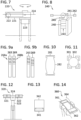
- FIG. 1 is a schematic side view of an embodiment of an offshore floater system (100) for a wave electricity generator comprising a lever arm (101) [i.e. a rocker arm, a tilting arm, a moment arm, a swinging power-transmitting lever, etc., which can be from any convenient material such as metals, metal alloys, wood, polymers, molded reinforced or prestressed concrete, combinations, etc., the materials can be provided with a convenient anticorrosion protection including metal plating, painting, sacrificial anode cathodic protection (SACP), etc., and which can provide leverage action multiplying the buoyancy force;
- the lever arm can (at least partially) rotate about an axis (108) [in a clockwise or counter-clockwise direction] and can be coupled with bearings;
- the bearings can be conventional roller and ball bearings which can be coupled with a freewheel;
- the bearings for oscillating movement can be from rings and flexible material such as rubber material of various designs which can suitably provide cavities
- the floaters (102) can be semi-submerged or submerged at different depths of submergence according to specific demands on the system] and rotatably coupled with a base member (103) [which can be from similar materials, can be comprised of hollow forms, tanks, floating platforms, pontoons, etc.; the base member can provide or can be coupled with constructions and (preferably perfectly watertight) installation spaces, casings, housings, etc., which be used to install hydraulics, electronics, power and other systems].
- the floaters (102) can be able to increase or decrease an effective length of the lever arm (101) [e.g.
- the offshore floater system (100) can be installed off shore and the base member (103) can be anchored to be able to react on a water level change [e.g.
- the system can be slidably coupled to a supporting construction (109) such as piers, rails, etc., anchored to the seabed (110) [which may be horizontal or slope] and provided high enough above the water level (104) [e.g. the crestline of the highest waves] to ensure that in storm conditions the system can be lifted from the sea; the system can make use of a buoyancy of the base member (103); the system can further comprise active or passive systems controlling the buoyancy, active coupling systems including motors, actuators, etc., sensing circuits to control, change, adjust, etc., the level of the base member (103) with respect to the wave floor for an optimal output of the system, or with respect to predetermined maximum settings /e.g.
- these control systems can be coupled with a remote controller, a cloud, a central controller, etc., with various local/distant wired/wireles communication techniques, the system can submerge /e.g. 5 to 20 meters/ or lift from the sea the floater system (100) if needed, e.g. in case of an emmergency to protect the system /e.g. a sea storm, a malevolent attack, freezing, the threat of a collision with a maritime transport, etc./, the components of the anchoring system can be further controllable, e.g.
- the base member can be level adjustable by different means /e.g. mechanical, hydraulic, pneumatic, electromagnetic, etc./, the buyoancy and the mass of the base member can be controllable actively or passively, the base member can be coupled with a mechanism configured to introduce the base member into the waves, to position the base member at different levels; the positioning mechanims can for example force the base member (103) into the wave thus increasing vertical distance traveled by the floaters (102) and analogically can be forced the floaters (102); the proposed ability to react on the water level change can further provide a wave energy conversion device that can operate despite tidal variations].
- the base member can be level adjustable by different means /e.g. mechanical, hydraulic, pneumatic, electromagnetic, etc./, the buyoancy and the mass of the base member can be controllable actively or passively, the base member can be coupled with a mechanism configured to introduce the base member into the waves, to position the base member at different levels; the positioning mechanims can for example force the base member (103) into the wave thus increasing
- the lever arm (101) can be coupled with an electric energy generator (105) [which can be an alternator, a dynamo, a homopolar generator, etc.] which can be coupled with an electrocomponent (not shown) [which can be provided in power, communication, signal, sensor circuits /e.g. which can be able to monitor at least wave amplitude and frequency, to measure the height of wave troughs and wave crests, etc.; load-monitoring devices, pressure transducers, pitot tubes, etc./, which can provide power components, communication components, controlling components, which can provide banks of components, distributed components, component arrays and which can be provided in one or multiple packing confomed to the offshore condition /e.g.
- the sensors can further monitor mechanical forces acting on the system components, hydrodynamic forces, wave impact forces, buoyancy forces, actuator pressing forces into the waves, energy output of the system, parameters of hydraulic and other system componets, depth parameters, etc.; the sensors can be used to adjust adjustable mechanical components such as gears, reducers, multipliers, (one-way) clutches, freewheels, brakes, hydraulic cylinders, etc.; continuous wave phase control can optimize the wave energy harnessing efficiency; the sensor can be acoustic inclusive of echo sound systems, electromagnetic inclusive of a radar, mechanical inclusive of pressure transducers, optical inclusive of laser beams, etc.; the sensors can be placed on any component of the system, on surrounding structures and constructions, etc.; drones can be used as sensing aids].
- the lever arm (101) can be coupled with a mechanocomponent (not shown) [which can convert a swinging movement into a rotational movement, which can transfer the rotational movement to the electric energy generator or generators, which can provide a shock absorbing function, relieve shock effects, etc.].
- a mechanocomponent (not shown) [which can convert a swinging movement into a rotational movement, which can transfer the rotational movement to the electric energy generator or generators, which can provide a shock absorbing function, relieve shock effects, etc.].
- a mechanocomponent (not shown) [which can convert a swinging movement into a rotational movement, which can transfer the rotational movement to the electric energy generator or generators, which can provide a shock absorbing function, relieve shock effects, etc.].
- the offshore system (100) can provide wired/wireless data transmissions in relation with electricity production, servicing, controlling, managing, etc.
- the data transmissions can be local [e.g. via communication interfaces, local wired/wireless networks] and distant [e.g. via offshore power and/or communication cables, satellite connections, telephone techniques, etc.].
- the data transmissions can include underwater acoustic techniques.
- the OFS can use any type of communication interfaces, lines, techniques and protocols.
- the OFS can be provided in a modular system [each component of the system (100) can be modularly scalable and/or exchangeable] .
- the OFS coupled with a rechargeable power source and the system can comprise thermal management systems to thermally manage charging and/or discharging the rechargeable power source [e.g. the systems can thermally manage the chargers and/or charging interfaces and/or charging cables] using air tempering systems, liquid tempering systems, liquid tempering systems using offshore water as a thermal medium, systems pumping cold water from the sea depths and recirculating water to cooler depths for heat exchange purposes, pumping compressed air or other fluids, etc.
- the systems can comprise ventilators, thermal exchangers, oil/water heat exchangers /with a biodegradable non-toxic hydraulic oil/, compressors, chillers, condensers, heaters, sensors, pumps, programmable controllers, thermal medium conducts, valves, etc.
- the wave electricity production components may need to be provided with a thermal management system [e.g. mechanocomponents such as gears, electrocomponents, electric energy generators, provided hydraulic or pneumatic systems, etc.].
- a thermal management system e.g. mechanocomponents such as gears, electrocomponents, electric energy generators, provided hydraulic or pneumatic systems, etc.
- the rechargeable power source can be banks of rechargeable capacitors and/or batteries of various known types.
- the source management system can manage charging and/or discharging the rechargeable power source [it can comprise various circuit topologies including electrocomponents such as converters, inverters, voltage regulators, power factor corrections, rectifiers, filters, controllers, processors, etc.].
- a rectifier can be coupled to a voltage converter to generate a consistent DC current to be used as a final source of electricity or to be converted to an AC current and delivered to a power generation grid, may be accumulated on shore and deliverd to a power distribution grid, etc.
- Progammable logic control devices may be incorporated into the system to control the generators, rechargeable power sources [e.g. the supercapacitors and batteries, etc.], and other components to deliver a consistent electrical current to the shore.
- Power generators may be arranged to generate electric power regardless of the direction a driveshaft rotates.
- FIG. 2 is a schematic perspective illustration of another embodiment of an offshore floater system (120) for a wave electricity generator comprising a lever arm (121) coupled with floaters (122) and rotatably coupled with a base member (123).
- the floaters (122) can be able to increase or decrease an effective length of the lever arm (121) according to wave paramaters (126) [which can be a wave height, width, depth /i.e. a zone wherein an influence from waves occurs under the water surface/, frequency, cadence, form, shape, volume, pitch, wave crest form, wave trough form, wavelength /e.g.
- the offshore floater system (120) can be installed off shore and the lever arm (121) can be coupled with an electric energy generator (not shown) [e.g.
- a conventional or variable-speed generator may be used, the generator may be powered using high pressure fluid or gas generated by a pump, a linear generator may be used uisng the oscillating motion, other lever arms may be used to leverage the reciprocating motion, wherein the mechanical advantage can be reversed where torque is traded for longer strokes in the reciprocating system; less moving parts can represent less energy losses trhough friction and inertia between components] which can be coupled with an electrocomponent (127) [which can be an offshore distribution (smart) substation, etc.].
- an electrocomponent (127) which can be an offshore distribution (smart) substation, etc.
- one lineal mile of ocean wave front with eight foot crest to trough waves and with a period of ten seconds can have one hundred eighty seven megawatts of power available.
- Waves in both shallow and intermediate depth water near the shore contain the same amount of energy as those in deep ocean water if the wave height and period are the same. Materials and construction costs may be less if the energy extraction system may be located near the shore [e.g. 500 feet off shore, up to 3000 feet off shore, etc.].
- the electricity generated by the system may be transmitted by cable to a power distribution center or transmitted to an electric motor or other device.
- FIG. 3 is a schematic side view of another embodiment of an offshore floater system (140) for a wave electricity generator comprising a lever arm (141) coupled with floaters (142) and rotatably coupled with a base member (143) [which can be anchored with anchoring lines which can be chain lines, wire lines, synthetic fiber ropes /e.g. Nylon, Polyester, Sisal, Polypropylene, etc./, e.g. in a tout-line anchorage system, etc., and which can be configured to provide an adequate buoyancy and stability /e.g. by means of stabilizing fins, bilge keels, protrusions, or other structures which can be provided to keep balance/].
- anchoring lines which can be chain lines, wire lines, synthetic fiber ropes /e.g. Nylon, Polyester, Sisal, Polypropylene, etc./, e.g. in a tout-line anchorage system, etc.
- anchoring lines which can be chain lines, wire lines, synthetic fiber ropes /
- FIG. 4 is a schematic perspective illustration of another embodiment of an offshore floater system (160) for a wave electricity generator comprising a lever arm (161) coupled with floaters (162) and rotatably coupled with a base member (163).
- the floaters (162) can be able to increase or decrease an effective length of the lever arm (161) according to wave paramaters (166).
- the offshore floater system (160) can be installed off shore and the lever arm (161) can be coupled with an electric energy generator (not shown) which can be coupled with an electrocomponent (167) [which can be an onshore distribution (smart) substation, etc.].
- FIG. 5 is a schematic side view of another embodiment of an offshore floater system (180) for a wave electricity generator comprising a lever arm (181) coupled with floaters (182) and rotatably coupled with a base member (183) which can be anchored to be able to react on a water level (184) change so that the floaters (182) and the base member (183) can at least partially or at least substantially follow contours of a wave (not shown).
- the elements of the invention can be preferably designed to allow shoaling to continue without causing the waves to break because breaking waves lose a large percentage of their energy to turbulent mixing, which reduces the energy available to the system.
- Waves created by wind moving ofer the surface form a vertical pressure front transported through the water masses in a horizontal direction, the pressure front can be equivalent to the amplitude of an incident wave, the stored wind's energy depends on the wind velocity and the length of time and the distance over which the wind is blowing which determines wave height and length.
- the wave length becomes shorter as the water decreases in depth.
- the total amount of enery stored in the water is composed of kinetic (associated with the water movement, i.e., mass and velocity) and potential (associated with the ability of a mass of water to fall a distance due to gravity). If the wave meets an obstacle it can be reflected and/or refracted. The wave can pass over the obstacle principally unafected.
- the positioning of a moving object can result in the mass set in motion by the passing wave which can activate an energy collecting and converting mechanism such as the proposed offshore floater system - a hydraulic pressure building system - a hydraulic motor - an electric energy generator, etc.
- the proposed system can be further optionally equiped with streaming devices such as side walls, barriers, chokes, panels, funnells, movable elements, etc., to concentrate the wave energy travelling through the pressure fronts.
- the barriers can be bottom fixed construtions or floating bodies.
- FIG. 6 is a schematic perspective illustration of another embodiment of an offshore floater system (200) for a wave electricity generator comprising a lever arm (201) coupled with floaters (202) and rotatably coupled with a base member (203) which can be anchored to be able to react on a water level (204) change and rotatably mounted to be able to react on a wave direction (to yaw in response to incident waves) and/or to work with the wind [e.g.
- FIG. 7 is a schematic side view of another embodiment of an offshore floater system (220) for a wave electricity generator comprising an unilateral lever arm (221) coupled with a floater (222) and rotatably coupled with a base member (223) which can be anchored to be able to react on a water level (224) change and rotatably mounted to be able to react on a wave direction [e.g. mounted on bearings arranged to remove radial and axial forces, the bearings can be prestressed and substantially free of looseness; the bearings can include inner and outer rings; flexible materials can be included in bearing systems; spring systems can be included; the bearings can be suitably spaced on a (central) axis to withstand impact of waves and to provide a desired stability].
- the lever arm (221) can be optionally coupled with a spring (not shown) with a spring constant to force the arm (221) into the return movement.
- FIG. 8 is a schematic perspective illustration of another embodiment of an offshore floater system (240) for a wave electricity generator comprising a lever arm (241) coupled with floaters (242) and rotatably coupled [e.g. via gears (245) wherein various systems of large and small gears, planetary gears, etc., can be provided; all kinds of gears can be utilized /e.g.
- the OFC can further comprise a magnetic element (248) [which can be one or more permanent magnets, magnetized buoyancy blocks, electromagnets or combinations] being in a magnetic relation with at least one component of the OFC [e.g. the magnetic elements (248) can be provided in, on, attached, coupled, etc.
- an anchoring system can comprise magnetically coupling coils or other magnetic elements (not shown) relative movement between the magnetic elements (248) can produce electricity which can be used together with the electricity produced by an electric energy generator (not shown) coupled with the lever arms].
- FIG. 9a is a schematic side view of one position of a base member (263) and an anchoring system (269) which can comprise magnetic elements (268a, 268b) [which can be permanent magnets, magnetic materials, electromagnets, coupling coils, coils with cores, with backing plates, etc., magnetically coupling coils or other magnetic elements (not shown)] wherein a relative movement between the magnetic elements (268a and 268b) can produce electricity.
- the electromotive force (emf) may be calculated from a flux density, a conductor coil length and a velocity of the relative movement.
- the coils can be connected in series to increase the output voltage and can be connected with other electrocomponents such as capacitors, rectifiers, invertors, comparators, etc.
- the electromagnets can be W-shaped, double U-shaped, I-shaped, E-shaped, etc.]
- FIG. 9b is a schematic side view of another position of the base member (263) and the anchoring system (269) as shown in FIG. 9a .
- FIG. 10 is a schematic cross sectional view of a lever arm (281) coupled with a floater (282) [which can have double convex faces] which can be used in the proposed system.
- FIG. 11 is a schematic cross sectional view of a lever arm (301) coupled with a floater (302) [which can have be a sphere] which can be used in the proposed system.
- FIG. 12 is a schematic side view of another embodiment of an offshore floater system (320) for a wave electricity generator comprising a lever arm (321) coupled with floaters (322) and rotatably coupled with a base member (323) which can be anchored to be able to react on a water level (324) change and rotatably mounted to be able to react on a wave direction [e.g. mounted on an axle, a pivot, a pole, a shaft, a spindle, a turning point, etc.].
- a wave direction e.g. mounted on an axle, a pivot, a pole, a shaft, a spindle, a turning point, etc.
- FIG. 13 is a schematic cross sectional view of a lever arm (341) coupled with a floater (342) [which can be a polyhedron /e.g. a cube/] which can be used in the proposed system.
- FIG. 14 is a schematic perspective view of another embodiment of an offshore floater system (360) for a wave electricity generator comprising a lever arm (361) coupled with floaters (362) [which can be cuboids, desks, plates, wave-energy absorbing panels, sandwiched constructions, constructions enabling throughflow, etc.] and coupled with base members (362) [the floaters (362) can function as base members] which can be anchored to be able to react on a water level (364) change [e.g. slidably coupled].
- FIG. 15 is a schematic side view of a freewheel (382) which can be coupled with a lever arm of the invention [any type of a freewheel can be used instead, e.g. comprising springpressed balls wedged between tapered surfaces of a gear ring and a disc, etc.] and which can be coupled with other mechanocomponents and components such as shafts, gears, electric energy generators, etc., and which can convert a swinging movement of the lever arm into a rotational movement whose parameters can be further modified, e.g. by gears, etc.
- FIG. 16 is a schematic side view of an electromagnetic freewheel (402) which can consist of a mechanical part and an electromagnetical part which can include magnetic elements [e.g. electromagnets (403)] which can be locally/distantly, automatically, mechanically, electromagnetically, electrically, electronically controlled to provide a selected functionality, wherein the freewheel can function for both rotational senses; electromagnetically can be controlled roller freewheels, sprag freewheels, ratchets and pawls, etc.
- clutches can be used which can be controlled mechanically, electrically, electronically, electromagnetically, hydralically, etc.
- Various types of clutches can be used such as conical, disc, sprag, overrunnig, etc.
- the controllable freewheels, clutches, gear locking mechanisms, etc., couplings can conveniently stop the operation of the system [e.g. during repairs, during a storm, while the system lifted from the sea, while a smaller number of electic energy generators should be operated as the waves diminish, etc.].
- FIG. 17 is a schematic oblique view of a homopolar generator (423) which can be coupled with lever arms of the proposed system (not shown).
- the homopolar generator (423) can be composed of a stator (423a) and a rotor (423b).
- the stator (423a) can be composed of a permanent magnet or an electromagnet which can have various forms, e.g. cylindrical, segmental, sectional, etc.
- the rotor can be composed of a magnetic conductor which can be provided with electrically conductive surface layer or can be composed of electrical conductors [e.g. in a composed form of conductive drums and discs].
- the rotor can be coupled with conductive bearings and with other electrocomponents of the power production and distribution system.
- homopolar generator types can be used [e.g. disc types, drum types, combined types, coupled types, etc.].
- Advantageously can be used types collecting electric energy by means of conductive bearings, but also types collecting electric energy by means of peripheral contacts because the system can be geared so that the homopolar generator can turn relatively slowly so that the peripheral collecting can be utility.
- Systems employing freewheels, clutches or other analogous devices and homopolar generators can provide substantially constant energy output over time and reduce the need for a frequency converter.
- FIG. 18 is a schematic oblique view of a variant of a homopolar generator (443) as shown in FIG. 17 wherein a stator (443a) can be composed of a magnetic conductor and a rotor (443b) can be composed of a permanent magnet or electromagnet. Similarly as shown in FIG. 17 the stator can have cylindrical or segmential forms. Different variants of the generators shown in FIGs. 17 and 18 can be provided proposing various winding, collector, electromagnet arrangements and combinations.
- FIG. 19 is a schematic perspective illustration of another embodiment of an offshore floater system (460) for a wave electricity generator comprising lever arms (461) coupled with floaters (462) and rotatably coupled with a base member (463) which can be anchored to be able to react on a water level (not shown) change and rotatably mounted to be able to react on a wave direction.
- FIG. 20 is a schematic perspective illustration of another embodiment of an offshore floater system (480) for a wave electricity generator comprising lever arms (481) coupled with floaters (482) and rotatably coupled with base members (483) [e.g. by meaning of a freewheel, a clutch so that different rotational speeds and swinging phases can be compensed] which can be anchored to be able to react on a water level change.
- the base members (483) can be flexibly coupled [e.g. by means of homokinetic joints, flexible shafts, shaft segments, etc.] so that the system can provide its functionality in a real offshore environment with three dimensionally formed waves (486).
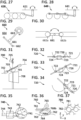
- FIG. 21 is a schematic side view of a lever arm (501) coupled with floaters (502) which can be used in the proposed system.
- the illustration shows a possibility of the proposed system to overturn [e.g. in case of a sudden squall, a wave, etc.] and still to maintaint the functionality of the system.
- This feature means that the system is apt to be installed in a real harsh environment of seas.
- a release mechanism can be provided to allow the lever arm (501) to rotate freely so that the forces of the strong waves cannot damage the construction [which can solve e.g. a twisted year wave problem].
- FIG. 22 is a schematic perspective illustration with a partial cutout of a lever arm (521) coupled with a floater (522) which can be used in the proposed system.
- the illustration shows that forms and shapes of lever arms and floaters can conveniently correspond and it further shows, that the construction of an arm can make possible for the water to flow in and flow out [e.g. by means of convenient openings, valves, nets, truss, etc.], overflow, etc.
- a form of the arm can be designed so that it represents a necessary lever mean but forms and obstactle to the wave to the smallest possible extent.
- FIG. 23 is a schematic side view of a base member (543) which can be anchored to be able to react on a water level (544) change and rotatably mounted to be able to react on a wave direction.
- the base member (543) can contain various means to stabilize its position in relation to a lever arm (not shown) so that the swinging movement could be maximized.
- Various means can be employed [e.g. anchoring system, creating balast zones (543a) /e.g. with ballast provided at or towards a lower end such that the center of gravity can be closer to the lower end and the center of buoyancy closer to the upper end/, suitably designed shapes and forms of the floaters (543) so that they can remain stable in an upright position, etc.].
- the illustration also shows, that natural servos systems can be used to establish a relatively stable position of the base member (543) such as hollow buoyancy zones, balast zones creating restoring torques to the vertical, a larger torque can be provided by more stable constructions such as embedded piers, rails, etc.
- natural servos systems can be used to establish a relatively stable position of the base member (543) such as hollow buoyancy zones, balast zones creating restoring torques to the vertical, a larger torque can be provided by more stable constructions such as embedded piers, rails, etc.
- FIG. 24 is a schematic side view of a base member (563) which can be anchored to be able to react on a water level (564) [e.g. by means of a slack anchoring line configuration which can include sinker weights, anchors attaching to the seabed, etc.].
- the illustration shows a convenient form of the base member (563) which can provide a required stability of the system and which can be various types of spars [e.g.
- the anchoring components can provide self-furling feature to roll with the punches of extreme waves so that the system can be preserved from a dammage rendering it inoperable; the anchoring means can minimize and/or optimize an undue vertical movement due to harmonic movement of the water below normal wave action depth.
- the different parts can have various forms [e.g. disc, bulb bulbous, dome, inverse dome, etc.] to attain a maximum stability in water and to minimize deviations from an upright position. All the system components, especially the spar buoys and the floaters can be designed to minimize the drag from the waves.
- FIG. 25 is a schematic perspective illustration of a lever arm (581) [which can be a conveniently hydrodynamically designed telescopically adjustable (or sliding) arm which can be controlled by various means such as natural control by wave forms, telematically controlled to adjust the output of the system e.g. accorging to weather conditions, waves' progress and parameters, etc.] coupled with floaters (582) [which can be hollow or foam balls] which can be used in the proposed system.
- a timed periodic adjustment device may be used to accomodate changes in the waves parameters.
- the arms (581) can include various conduits, installations spaces, hermetically sealed spaces, watertight spaces, thermally managed spaces, etc.].
- the lever arm (581) can be advantageously coupled with one or more underwater sail components (588) [which can be supported in the water in a manner such that it will be moved back and forth in an oscillatory manner by the movement of the water beneath the waves.
- the underwater sails can be reefable, foldable, extendable, regulable, rotatably mounted to orient the apparatus, etc.
- the sails can be horizontally or vertically rotatably mounted.
- lever arm (581) can be coupled by various means such as connecting rods with the vertically rotated underwater sails, etc., or the underwater sails and the proposed offshore floater system can be coupled with a shaft, a gear, a rack, an electric energy generator, etc.
- Secondary underwater sail concept can be further used which interact with the underwater sail components (588) in a manner to capture energy on a leeward side.
- Other structures as breakwater reflecting the energy seaward can be used.
- the breakwaters creates standing waves which are different from travelling waves.
- the breakwaters and other reflecting devices, if phased properly e.g.
- the separation can be changeable
- the reflectors can be driven by motors in pivotal (or rectilinear) motion according to for example transducer signals processed through computer [e.g. amplified, attenuated, phased, etc.].
- FIG. 26 is a schematic oblique illustration showing possibility of a lever arm (601) [only a central part shown] to be coupled with a crankshaft (608) which can be coupled with an electric energy generator (605).
- the shown arrangement can advantageously convert a swinging movement of the arm (601) into a rotational one of the shaft (608) and the generator (605).
- the lever arm (601) can be coupled with other mechanocomponents such as energy transfer mechanisms comprising fluid or gas compressors and storage elements such as containers, tanks, expandable bladders filled with an inert gas, such as nitrogen, etc., and converting the kinetic energy into potential energy, storing the potential energy and further converting the potential energy into electrical energy.
- Various mechanocomponets can be housed within one or multiple bodies.
- FIG. 27 is a schematic side view showing possibility of a lever arm (621) which can be coupled with mechanocomponents (628) [e.g. an arm, a connecting rod, a flywheel, a cheek, a crank web, a belt, a chain, a joint, a cardan, a shaft, a sprocket, a cog wheel, etc.] and with electric energy generators (not shown) [which can be coupled in parallel, in series, in tandem, in arrays, etc., to individual mechanocomponets].
- mechanocomponents e.g. an arm, a connecting rod, a flywheel, a cheek, a crank web, a belt, a chain, a joint, a cardan, a shaft, a sprocket, a cog wheel, etc.
- electric energy generators not shown
- the shown arrangement can convert a swinging movement of the arm (621) into a rotational one.
- FIG. 28 is a schematic side view showing possibility of a lever arm (641) which can be coupled with mechanocomponents (648) [e.g. a transmission system which can be similar to steam locomotives and far more elaborated than as shown, etc.] which can be provided in a casing (not shown).
- mechanocomponents e.g. a transmission system which can be similar to steam locomotives and far more elaborated than as shown, etc.
- FIG. 29 is a schematic plan view of another embodiment of an offshore floater system (660) for a wave electricity generator comprising a lever arm (661) coupled with floaters (662) and rotatably coupled with a base member (663) which can be installed in an offshore water (664) and rotatably mounted to be able to react on a wave direction [e.g. mounted on a suitable thrust bearing system].
- a lever arm 661 coupled with floaters (662) and rotatably coupled with a base member (663) which can be installed in an offshore water (664) and rotatably mounted to be able to react on a wave direction [e.g. mounted on a suitable thrust bearing system].
- FIG. 30 is a side view of a lever arm (681) coupled with floaters (682a, 682b) which can be used in the proposed system.
- the illustration shows that embodiment of the invention can be provided with releasable floaters which can be released in case of extreme weather conditions off shore so that the system can be protected from strong impacts of waves.
- elements of the system can be designed to fail in a benign manner to protect the integrity of the system in extreme conditions.
- the floaters (682) can be for example simple inflated balls the price of which can be inferior to the price of other system components, mainly mechanical and power components.
- the released floaters (682) can be attached by ropes, traceable by GPS or other antenna systems, etc. Similarly inflatable/deflatable floaters, airway lines, buoyancy controllers, pressure members such as compressors and valves, etc., can be used.
- the system can be alternatively protected and/or optimized by flooding a base member and the floaters (682a, 682b) so that the system can sink to a lower limit, the inner spaces can be watertight sealed for this event [the system components can for this purpose comprise load release and re-establish means such as inlets, outlets, vents, valves, pressure sensing switches, solenoids, release pins or cams, active/passive systems, etc.].
- water can be displaced from the base member and the floaters (682a, 682b) by various means such as compressors, by means of pressurised air or liquid reservoirs, etc.].
- the illustration further shows that the floaters (682a, 682b) can be differently sized.
- the system can be programmed to enter a storm survival mode wherein the energy transfer mechanism can be for example locked. Similarly a control system can shut the energy transfer mechanism in calm conditions when the wave energy is not able to run an electric energy generator.
- the base member and the floaters (682a, 682b) can further have adjustable buoyancy and adjustable mass; they can be provided in multiple buoyancy modes [e.g. subsurface, above the surface modes, etc.].
- the adjustable buoyancy can control the energy capture in according to wave parameters such as wave size and wave period.
- the floaters (682a, 682b) can have inertia, drag and buoyancy components designed for particular applications to maximize the energy capture. They can have various forms [e.g. with a large surface area perpendicular to the direction of the undulating force to create a large drag and increased mass, etc., to capture the wave energy which is greatest at the water surface and decreases with the depth which can be used to optimalize the energy capture according to wave parameters /e.g. to lower the energy capture in case of storm-waves/].
- the lever arm (681) can be configured to sustain the loads transferred from the floaters (682a, 682b) to other energy capturing components inclusive of slamming loads in extreme waves, etc.
- hydraulic systems can further include components such as (shared) hydraulic conduits, pumps of various types inclusive of reciprocating piston pumps, double acting pumps, etc., valves, actuators, hydraulic storage tanks, variable capacity hydraulic machines, spike suppression devices, control circuits keeping revolutions essentially constant to generate alternating current with or without a frequency converter
- various types of hydraulic motors or the like can be employed such as gear, piston, vane, motors having variable displacement volume per revolution, etc.
- various motor coupling can be used /e.g. in parallel, to the same shaft, etc./; by means of various hydraulic systems the wave energy can be converted into hydraulic energy which can be stored and/or converted into electric energy; analogically pneumatic motors and systems can be provided to convert and/or
- FIG. 31 is a schematic perspective illustration of another embodiment of an offshore floater system (700) for a wave electricity generator comprising a lever arm (701) coupled with floaters (702) and rotatably coupled with a base member (703) which can be anchored to be able to react on a water level (704) change and rotatably mounted to be able to react on a wave direction [e.g.
- the lever arm (701) can be coupled with an electric energy generator (not shown) which can be coupled with a wind energy system (705) [e.g.
- an offshore power production unit with power electronics and control and coupled via an offshore power cable with an onshore load, an offshore charging station, etc.].
- above-water structures such as vertical (airfoil-) sails, blades, rudders, etc. can be used to orient the system.
- FIGs. 32 to 34 are functional schematic illustrations of another embodiment of an offshore floater system (720) for a wave electricity generator comprising a lever arm (721) coupled with floaters (722) configured to be able to increase or decrease an effective lenght of the lever arm (721) rotatably coupled with a base member (723) which can be anchored to be able to react on a water level (724) change.
- the figures show various phases and positions of the system relative to the advancing wave (726).
- FIG. 35 is a functional schematic illustration of another embodiment of an offshore floater system (740) for a wave electricity generator comprising a lever arm (741) coupled with a floater (742) and rotatably coupled with a base member (743) which can be anchored to be able to react on a water level (744) change.
- the figures show the working principle of the proposed system with waves's cyclic movement and the base member (743) with the floaters (742) being able to react on it and swing the lever arm (741).
- the proposed system can employ the horizontal and the vertical vector elements of wave motion energy which can be transmitted by the force of viscosity between water particles.
- FIG. 36 is a partial schematic oblique view of another embodiment of an offshore floater system (760) for a wave electricity generator comprising lever arms (761) coupled with floaters (762) and rotatably coupled with one or more base members (763) by means of a mechanocomponent (768a) [e.g. a freewheel, a clutch so that different rotational speeds and swinging phases can be compensed for a shaft (768b) which can be coupled with another mechanocomponent such as gears and/or with an electric energy generator (765) /e.g. a homopolar generator/].
- the base member (763) can be anchored to be able to react on a water level (764) change.
- FIG. 37 is a partial schematic oblique view of an array of offshore floater systems (780) for a wave electricity generator comprising lever arms (781) coupled with floaters (782) and rotatably coupled with one or more base members (not shown).
- the figure shows a possibility of coupling floater systems (780) variably into arrays in X-axis and/or Y-axis (and/or Z-axis) directions [e.g. by means of flexible shafts, joints, flexible connections, etc.] in various patterns [e.g. rows, hexagonal, star, V, Y, etc.] to efficiently exploit the wave energy.
- Offshore power networks which can include or be coupled with other components such as frames, outrigger reactor means such as floats, supports, pipes, (flexible) mechanocomponents, moorings, (static/dynamic) anchoring structures, marine rechargeable power sources, offshore power production units, control units, mobility units, auxiliary buoyancy units, power and communication lines, power and communication interfaces, marine attachments, navigational aids, etc.] can be formed.
- a control system can operate the array in different modes [e.g. a storm mode, a partially activated array mode, a calm conditions mode, etc.].
- the control system with a mobility system can deplace, rotate, etc., the array according to weather conditions and forecast and waves direction.
- the arrays (780) can be anchored in multiple ways; a center anchor can be provided which can further house electronics, hydraulics, pneumatics, control elements, etc.; peripheral anchors, anchors arrays, combined static/dynamic systems, etc.
- FIG. 38 is a schematic oblique view of a pendulum type electric energy generator (805) which can be used in the proposed offshore floater system.
- the generator (805) can include a stator (802) which can be coupled with a base member (803) and a rotor (804).
- the stator (802) and the rotor (804) can include magnetic elements [e.g. permantent magnets, electromagnets, coils, cores, backing plates, etc.].
- a relative movement between the stator (802) and the rotor (804) can produce electricity.
- a lever arm (not shown) can pivot about an axis (808).
- FIG. 39 is a schematic side view of a spring type electric energy generator (825) which can be used in the proposed offshore floater system.
- the generator (825) can include a stator (822) which can be coupled with a base member (823) and a rotor (824).
- the stator (822) and the rotor (824) can include magnetic elements [e.g. permantent magnets, electromagnets, coils, cores, backing plates, etc.].
- a relative movement between the stator (822) and the rotor (824) can produce electricity. Shown is an axis (828) where can be coupled a lever arm (not shown).
- the illustration also shown a self regulating principle or an adaptive control which can be employed in power generation wherein one or more coils may be energized in various types of generators which can increase resistance and the ability of an armature to turn and at the same time by increasing the electrical field strength [which can be computer-optimized] incresases the electrical power output of the generators. In this way a maximum amount of energy available in water in varying sea states can be captured.
- various damping structures can be used such as springs, dashpots, various schemes to vary damping and restoring forces, etc.
- Various controls can be provided to increase resistance such as pressure sensors, motion sensors, (roller) contacts, etc.
- FIG. 40 is a schematic oblique view of a translational type electric energy generator (845) which can be used in the proposed offshore floater system.
- the generator (845) can include a stator (842) which can be coupled with a base member (not shown) and a mover (not shown) which can be coupled with external actuators (844) [which can be mechanical, pneumatic, electromagnetic].
- the stator (842) and the mover can include magnetic elements and a relative movement can produce electricity.
- lever arms (not shown) can be coupled with a pulley system, a connecting rods system, etc., and alternately push or pull the external actuators (844).]
- FIG. 41 is a schematic oblique view of a coil type electric energy generator (865) which can be used in the proposed offshore floater system.
- the generator (865) can include a stator (862) [which can be one or more coils, electromagnets, permantent magnets, etc.] which can be coupled with a base member (863) and a rotor (864) [which can be one or more permantent magnets, electromagnets, coils, etc.].
- a relative movement between the stator (862) and the rotor (864) can produce electricity. Shown is an axis (868) where can be coupled a lever arm (not shown).
- FIG. 42 is a schematic side view of another embodiment of an offshore floater system (880) for a wave electricity generator comprising lever arms (881) coupled with floaters (882) and rotatably coupled with base members (883a, 883b) which can be moored to be able to react on a water level change.
- the illustration shows a possibility of the invention to stabilize the base members (883a, 883b) by other means than coupling with the seabed [e.g.
- the mooring system may further provide restraint or excitation to the system to influence its properties.
- the mooring system and/or the joints between the base members (883a, 883b) can be configurated to (resonantly) respond to heave and sway motions of the elements in such a way as to maximize a power absorption and a power output
- the base members (883a, 883b) can form a chain-like structure which length can be comparable to the incident wavelength to span at least two crests; in small waves the system can give a resonant response, in extreme waves various constraints may be provided so that the system give a benign response.
- the base members (883a, 883b) can be located in tandem, can form chains, networks affixed to a common structural floating frame and allowed to articulate in the same manner (rectilinear or pivotal), etc.
- FIG. 43 is a schematic illustration of sea waves representing a real environment for an off shore installation of the proposed system.
- the illustration shows that the wavelength at sea (904) [or another off shore water] can differ and that for shorter wavelength the system may need a modification of lever arms.
- the solution of the problem is shown in FIG. 44 .
- FIG. 44 is a schematic side view of another embodiment of an offshore floater system (920) for a wave electricity generator comprising lever arms (921a, 921b) coupled with floaters (922) and rotatably coupled with a base member (923) which can be anchored to be able to react on a water level change.
- the illustration shows a possibility of the invention to remain functional for shorter wavelength by providing shorter lever arms (921a, 921b) [which can be provided as separate constructions coupled with an axis (928) and/or which can be lockable/unlockable to form one lever arm wherein various locking or controlling means can be provided such as mechanical, hydraulic, electromagnetic, etc., the lever arms (921a, 921b) can be coupled with various mechanocomponents such as shafts, clutches, freewheels, concentric components, etc.].
- FIG. 45 is a perspective illustration of a lever arm (941) which can be provided with floater movements controlling structures (948) [e.g. rubber barriers, springs, protrusions, notches, stops, controls, electromagnets, mechanical, pneumatic, hydraulic structures and/or actuators, and other regulating structures] which can passively or actively control a position of a floater (942) [e.g. a buoyancy force can pass the floater (942) through a rubber barrier at a certain threshold; sensing circuits can be provided and coupled with actuators, etc.] and provide a stabilizing effect on the energy output of the system.
- the arm (941) can be open to a throughflow of an offshore water (944).
- FIG. 46 is a schematic perspective illustration of another embodiment of an offshore floater system (960) for a wave electricity generator comprising a lever arm (961) coupled with floaters (962) [e.g. (multi-) wing floaters, disc floaters, etc., producing at least lifting forces and being rotatably coupled] and with a base member (963) which can be anchored to be able to react on a water level (964) change.
- the illustration shows a possibility of the invention to adapt the orientation of the floaters (962) to the undercurrents, wave directions, etc., to optimalize output of the system, to protect the system.
- the floaters (962) can be individually controllable, adjustable, etc., so as to affect an effective length of the arm (961) and the floaters (962) can further be optionally slidably mounted to the lever arm (961).
- the floaters (962) can have small depth nad freeboard to provide complete submergence and emergence (hydrostatic-clipping) in large waves.
- FIG. 47 is a perspective view of a floater (982) optionally rotatably coupled with a lever arm (981) which can be used in the proposed system.
- the floater (982) can reduce drag with help of various means [e.g. hydrodynamical shape such as conical shape, slots (982c), hydrofoil profiles, blades, discs, wedges, etc.].
- the floater (982) can generate lift with help of various means [e.g. with its buoyancy, hydrofoil profiles, etc.].
- the connection between the floater (982) and the lever arm (981) can use various types of joints [e.g.
- the joints can enable various movement such as wobbling, rocking, etc., if desired] which can be controllable [e.g. mechanically, hydraulically, pneumatically, electromagnetically, naturally by the hydrodynamical shape, etc.; various types of motors, actuators, sensors, etc., can be used] so that a proper position of the floater (982) can be obtained.
- FIG. 48 is a schematic perspective illustration of another embodiment of an offshore floater system (1000) for a wave electricity generator comprising lever arms (1001) coupled with a floater (1002) [which can have a billowed surface and can be from a sheet of a rigid and/or flexible floating material such as polymers /e.g.
- PU heavy duty polyurethane
- polyethylene polyethylene
- polypropylene polyamide
- nylon buoyancy plastics
- the floating materials and/or bodies can include cavities of various forms] and rotatably coupled with a base member (1003) which can be anchored to be able to react on a water level (1004) change so that the floaters (1002) and the base member (1003) can substantially follow contours of a wave (not shown).
- the lever arms (1001) and the floater (1002) can be of a fan design, a roll-up design, etc., to fold and unfold, conceal, etc., sections which system can be motor, hydraulics, wave-action, etc., actuated. If the floater (1002) is too flexible, development may be coordinated with the wave motion. The floater (1002) may be flexible to some degree to maintain a necessary stiffness [drag, turbulence considerations may be allowed]. Biological growths may be factor which may be further accounted for the system components design.
- FIG. 49 is a variant of a system (1020) as shown in FIG. 48 wherein a floater (1022) can reduce drag and provide lift by means of a sandwiched structure which can include a throughflow space (1022c) [which can be further conveniently hydrodynamically shaped], an upper buoyancy structure (1022a) and a lower buoyancy structure (1022b) [wherein the buoyancies of the structures (1022a, 1022b) can be preset to determined values to obtain an optimal position of the floater structure (1022) in relation to waves and undercurrents to optimize the dynamic response of the system wherein either of the structures (1022a, 1022b) can be provided partially under the water level in various depths /e.g.
- the wave energy can be optimally collected up to L/2 depth from the sea surface wherein L is the wavelength, the distance of water particle travel at the L/2 depth is four percent of the distance of particle travel at the surface, energy is related to the square of the motion of water particles; 99,8 percent of the total energy is within the L/2 depth; water particle motions due to wave motion are nearly circular in deep water (the depth up to the L/2) and flatten to become flattened in shallow water (the depth less than L/20) and elliptical in between, with larger motions occurring near the surface and diminishing in orbital motion to the depth/; the buoyancies can be controllable by various means].
- Lever arms (1021) can be optionally articulated to be able to follow contours of the waves, lever arm's portions can be coupled with power extraction systems, springs; different magnitudes of constraint may be applied to increase power capture according to waves parameters /e.g. by means of orientation of provided joints/; the lever arms (1021) can be actively or passively variable].
- a base member (1023) can be anchored or moored by various means to be able to to react on a water level change.
- FIG. 50 is a schematic side view of another embodiment of an offshore floater system (1040) for a wave electricity generator comprising a pendulum-like lever arm (1041) (shown in a median and an upper position) coupled with a floater (1042) [which can be from a bend tubular or similar form enabling throughflow or analogical construction constructed conforming to the fluid dynamics with various inflow, outflow openings and lines, valves, flow hampers, buoyancy and mass zones, etc.] and rotatably coupled with a base member (1043) [in various wave phases gravity and buyoancy forces can make the elements relatively oscillate or rotate] which can be anchored to be able to react on a water level change [e.g.
- the floater (1042) can be hidden at least partially in the natural water.
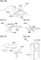
- FIG. 51 is a schematic perspective view of another embodiment of an offshore floater system (1060) for a wave electricity generator comprising a lever arm (1061) coupled with floaters (1062) and rotatably coupled with a base member (1063) [which can be a buoyant or non-buoyant housing for electro- and mechanocomponents such as various shafts, gears, clutches and power electronics, communication electronics, etc.] which can be positioned between the floaters (1062) on the lever arm (1061) so that the floaters (1062) can follow contours of waves (1066).
- the lever arm (1061) can be via the base member (1063) coupled with a weight (1068) [which can have various shapes, forms and provide other functions /e.g.
- the base member (1063) can host sensors, actuators, etc./] which can substantially keep the base member (1063) in a relatively vertical position which can ensure a relative rocking motion of the lever arm (1061) which kinetic energy can be further converted into other types such as a potential energy, an electric energy, etc.
- the illustration shows the embodiment in which the base member (1063) can be provided only in a splash (temporary) contact with an ambient water which can be advantageous for servicing, maintenance, components' accessibility, but also can have less demanding requirements in terms of watertight action in comparison with (constantly) fully submerged (pressurised) solutions.
- FIG. 52 is a schematic perspective illustration of an offshore installation of another embodiment of an offshore floater system (1080) which can be coupled with the shore (1089) via a power cable (1088) [which can further perform a mechanical mooring function wherein in situ anchoring can be further provided by the system (1080)].
- Various load types can be provided on shore such as power grids, electric motors, desalinations centers, industrial, recreational, etc., facilities, energy systems of engineering and/or architectural constructions, etc.
- the floater system (1080) can be "mobile", i.e. can be anchored ad hoc, temporarily, can be provided as a foldable kit, skid mounted kit, etc., can be deployed [e.g. from an onshore vehicle] if needed, or can be provided as relatively permanent [e.g. 20 years] offshore power installation, etc.
- FIG. 53 is a schematic perspective illustration of an offshore installation of another embodiment of an offshore floater system (1100) which can be coupled with a water vessel (1109) [which can be a commercial vessel, a multipurpose vessel, a power production vessel, etc.] via a power cable (1108) [wireless coupling via wireless power/communication interfaces can be contemplated as well /e.g. inductive, capacitive, magnetodynamic, electromagnetic, resonant, non-resonant, combinations, etc., powerline communication or other wired or wireless communication means can be provided].
- Various load types can be provided by the vessel (1109) such as rechargeable power sources, hydrogen energy generation and storage systems, loads, auxiliary devices, electric motors, facilities, etc.
- the floater system (1100) can be "mobile"[e.g. can be anchored by dynamic anchoring, demontable, modularly scalable, etc.].
- FIG. 54 is a schematic perspective illustration of an offshore installation of another embodiment of an offshore floater system (1120) which can be part of an offshore charging station for overwater and/or underwater vessels at least partially electrically driven which can comprise at least one rechargeable power source [e.g. providing traction power, auxiliary power, etc.] and which can include a base floater (1123) coupled with a static installation housing (1128) which can be modularly configured and can include a wave energy controller with power and communication modules adapted to particular system demands /e.g. on the rated operating voltage and current/].
- One or more lever arms coupled with one or more floaters can be rotatably coupled with the base floater (1123).
- FIG. 55 is a schematic illustration of another offshore installation of an offshore floater system (1140) which can be coupled with water vessels (1149a, 1149b) via a power/mooring cable (1148) wherein other anchoring systems [e.g. bottom anchoring systems (1149)] can be used.
- the illustration shows an advantage of a "mobile” system which can adapt to weather conditions and "track” waves.
- the illustration shows advantages of an easily deployable system for the wave electricity generation.
- the illustration shows the floater system (1140) with more anchoring and mooring points [or a combination of more anchoring systems inclusive of active and passive positioning systems] which can ensure a convenient orientation towards local incident waves to optimize the wave energy collection [or to move the system (1140) from a stormy area, etc.].
- FIG. 56 is a schematic side view of another embodiment of an offshore floater system (1160) for a wave electricity generator comprising a lever arm (1161) coupled with floaters (1162) and rotatably coupled with a base member (1163) [which can be a buoyant or non-buoyant housing for hydraulic, pneumatic, power and communication systems, etc.] which can be positioned between the floaters (1162) under (or above, or in another position) the lever arm (1161) so that the floaters (1162) can follow contours of waves (not shown).
- a lever arm 1161 coupled with floaters (1162) and rotatably coupled with a base member (1163) [which can be a buoyant or non-buoyant housing for hydraulic, pneumatic, power and communication systems, etc.] which can be positioned between the floaters (1162) under (or above, or in another position) the lever arm (1161) so that the floaters (1162) can follow contours of waves (not shown).
- the lever arm (1161) can be coupled with a pneumatic and/or hydraulic system (1168) [which can include respective hydraulic/pneumatic pressure building systems, hydraulic/pneumatic motors which can be coupled with or include an electric energy generator and/or a rechargeable power source, etc., to produce, respective to store the electric energy].
- a pneumatic and/or hydraulic system (1168) which can include respective hydraulic/pneumatic pressure building systems, hydraulic/pneumatic motors which can be coupled with or include an electric energy generator and/or a rechargeable power source, etc., to produce, respective to store the electric energy.
- FIG. 57 is a schematic perspective view of another embodiment of an offshore floater system (1180) for a wave electricity generator comprising a lever arm (1181) coupled with a floater (1182) [e.g. integrated into the floater body, forming a framework, etc.] and rotatably coupled with a base member (1183) [e.g. two parallel concrete pylons] housing mechanocomponents and electrocomponents (eventually pneumatic or hydraulic systems) and enabling hoisting and dropping the floater (1182) into waves (1186).
- the shown embodiment can form a chain with multiple production units and any component of the system can be coupled with other green energy systems such as solar panels, wind energy systems, etc.]
- FIG. 58 is a schematic perspective illustration of an offshore floater method for generating wave electricity, the method comprising the steps of deploying an offshore floater electricity generator (1200) including one or more lever arms (1201) coupled with one or more floaters (1202) and rotatably coupled with a base member (1203) including or coupled with an electricity generator (not shown) [which can be provided inside in a watertight installation] (S1221);
- FIG. 59 is a schematic illustration showing the possibilities of the proposed system and method to deploy a (modularly designed) offshore floater electricity generator (1240), which can be fabricated in one area [e.g. U.S.] and prepared in a transportable packaging (1250) to supply the wave electricity for another area (1251).
- a (modularly designed) offshore floater electricity generator (1240) which can be fabricated in one area [e.g. U.S.] and prepared in a transportable packaging (1250) to supply the wave electricity for another area (1251).
- FIG. 60 is a schematic perspective view of another embodiment of an offshore floater system (1260) for a wave electricity generator comprising lever arms (1261) which can be an integral part [e.g. a framework, an iron core of a foam material, etc.] of floaters (1262) and rotatably coupled [e.g.
- a base member (1263) which can be a buoyant casing for mechanical, power and communication components, etc.
- floaters (1162) which can be disposed in any other than shown pattern to collect the wave energy;
- the shown plurality of floters can be substituted by two floaters;
- the plurality can be coupled with a common (flexible, articulated) shaft by means of one-way clutches, freewheels, etc.] so that the floaters (1262) can follow contours of waves (1266).
- the systems (1260) can be provided in chaines, groups, etc.
- the both fulcrums can be stabilized in the waves (1266) by various means such as mechanical, hydraulic, pneumatic, electromagnetic constructions, springs, dampers, bottom rest supporting constructions, anchorings, moorings, buoyant anchored constructions, water vessels, onshore vehicles, etc.
- FIG. 61 is a front view of a mechanical coupling of three axes (1268a, 1268b, 1268c) which can be used in the proposed system.
- the illustration shows, that multiple axes as for example shown in the embodiment of FIG. 60 can be coupled by various means such as gears, variators, belts, chains, electromagnetic couplings, etc., so that a multiple secondary axes coupled in a rotative or swinging motion with floaters (not shown) can transfer the rotative or swinging motion [e.g. via a freewheel, or a (one-way) clutch, a lockable/unlockable coupling, etc.] to one or more primary axes coupled with an electric energy generator (not shown).
- an electric energy generator not shown
- FIG. 62 is a schematic perspective view of another embodiment of an offshore floater system (1280) for a wave electricity generator comprising a lever arm (1281) [which can have a form of a crankshaft which can have various shapes, include counterweights, have forms of discs or wheels with one or more floaters provided for example round the perimeter, etc.] which can be coupled with a floater (1282) and rotatably coupled with a base member (1283) [which can be buoyant or non-buoyant and which can house power and communication components, etc.].
- the floater (1282) can follow contours of waves (1286) [e.g.
- buoyancy of the floater (1282) can be controllable to position the system in different levels; various means can be used such as pneumatic, hydraulic, electromagnetic systems, valves, inlets, outlets, etc.; the buoyancy can be thermally controlled by various heating or cooling systems; the seas or oceans are stratified due to differencies in density, with warmer, lighter, less salty water layering on top of heavier, colder, saltier water]. Fulcrums can be stabilized in the waves (1286) by various means [e.g. buoyant, or bottom rest supporting constructions].
- FIG. 63 is a schematic side view of another embodiment of an offshore floater system (1300) for a wave electricity generator comprising lever arms (1301a, 1301b) [which can provide devices exploiting translational movement as shown or at least partially rotational /that means that the lever arms (1301a and 1301b) can be slidably, rollably, rotationably, etc., coupled/ movement or combinations to collect x-axis and y-axis and/or rotational forces; the substantially horizontal arm (1301a) can couple more substantially vertical arms (1301b)] which can be coupled with a floater (1302) and rotatably coupled with a base member (not shown) [which can be buoyant or non-buoyant].
- lever arms (1301a, 1301b) which can provide devices exploiting translational movement as shown or at least partially rotational /that means that the lever arms (1301a and 1301b) can be slidably, rollably, rotationably, etc., coupled/ movement or combinations to collect x-axis and y-
- the floater (1302) can follow contours of waves (not shown) [e.g. can follow orbital, elliptic, flattened movement of water particles]. Fulcrums can be stabilized in the waves by various means [e.g. buoyant, or bottom rest supporting constructions].
- the exploiting devices can be mechanical, pneumatic, hydraulic, electromagnetic. They can include various means to collect the wave energy and convert it into an useful energy such as electric energy, potential energy, etc.
- the devices can be pumps, gears, levers, pulleys, electromagnets.
- the lever arms (1301a, 1301b) can be mutually slidably, rollably, rotatably, etc. coupled.
- the whole of the system (1300) can be provided in an effective contact with an underwater environment affected by the wave action.
- Various sensing circuits can be used to determine this environment wherein the wave depth is only one of the potentially important parameters; further can be water velocity, direction, persistance, frequency, impact strength, etc., wherein accordingly various sensors can be provided.
- the whole of the system (1300) can be positioned to the sphere of influence where the wave energy can be collected by various means which can be buoyant and/or non-buoyant constructions inclusive of natural structures and/or constructions with other purposes such as oil platforms.
- various anchoring systems can be used inclusive of static and dynamic anchoring, position keeping, etc. Drones can be used or an autonomous drive system do deplace the system to the most appropriate underwater area.
- FIG. 64 is a schematic perspective view of another embodiment of an offshore floater system (1320) for a wave electricity generator comprising a lever arm (1321) [which can have a form of a crankshaft] which can be coupled with floaters (1322) and rotatably coupled [e.g. via a variable flywheel (1328) which can change the momentum by various means, e.g. weights] with a base member (1323) [which can include an electric energy generator].
- the floaters (1322) can follow contours of waves similarly as shown in FIG. 62 [freewheels can be provided on the crankshaft (1321) between the floaters (1322)]. Fulcrums can be stabilized in the waves by various convenient means.
- FIG. 65 is a schematic perspective view of another embodiment of an offshore floater system (1340) for a wave electricity generator comprising lever arms (1341) which can be an integral part of floaters (1342) [which can be slidable, stowable, reefable, etc.] and rotatably coupled with a base member (1343) [which can contain mechanocomponents, electrocomponents and an electric energy generator].
- the system may be easily transportable, deployable accordingly to the proposed method and modular.
- FIG. 66 is a schematic side view of another embodiment of an offshore floater system (1360) for a wave electricity generator comprising an unilateral lever arm (1361) coupled with a floater (1362) and rotatably coupled with a base member (1363) which can be anchored to be able to react on a water level (1364) change.
- the floater (1362) can be delimited by a structure as breakwater (1365) reflecting the energy seaward.
- Offshore floater systems situated in seas or in oceans may be object of various tidal ranges varying from near zero to about 53,5 feet (16 meters) and averaging about 2 feet (0.6 meters) in the open ocean.
- level adjustable base members or level adjustable bottom rest supporting constructions may be designed to cope with a tidal range in a selected area for placement of the OFS.
- Pasive e.g. slack-line anchorages, sliding anchorages, etc.
- active anchorage systems systems with active components
- the OFSs operated/temporarily operated under water level may provide atmospheric pressure in its inner space (e.g. in the container which can be filled with dry air, nitrogen, etc.) which may be advantageous for its electronic components or it may be kept at another pressure.
- the OFSs may include further components enhancing their functionality such as installation spaces, connecting boxes, electricity meters, main switches, input/output terminals, fuse distributions, etc.
- the electronic control and communication components may be housed in electromagnetically shielded spaces. All electrical and electronical equipment may be particularly protected against moisture, salt water and grid to prevent failure of power and electronic components. External controls may be suitably adapted to function in offshore conditions. Subsea plugs, isolation bushings, cathodic protection and special resistive materials and anticorrosive surface treatments may be used.
- the OFSs may be situated offshore in the Arctic, the Antarctic, subpolar and cold seas. In that case, components of the OFSs may be designed to be conform with cold/extremely cold/temporarily cold conditions.
- a special insulation of offshore power cables (which may be posed on ice), power cables may be provided.
- a special thermal insulation of marine rechargeable power sources e.g. rechargeable power sources in containers) may be provided. Thermal management systems of the OFSs and the marine rechargeable power sources may require heating systems.
- the present invention may provide an offshore floater system (OFS) which can propose a compact design which makes it able to withstand harsh conditions at seas since the wave energy can be efficiently developed on open seas, the high seas, unprotected areas, etc.
- the design conforms the wave theory with practical requirements of the wave energy conversion.
- the device has the advantage of working in harmony with the offshore environment.
- the system can be deployed near docking facilities, offshore charging stations, recreational areas, etc.
- the present invention can provide a technologically not complicated and easily to service offshore floater system which can generate wave electricity.
- the proposed floater system configured to be able to adapt an effective length of a working lever arm to wave parameters and the proposed base member being able to react on a water level change can form a system which can bring a high efficiency in harvesting the wave energy.
- the OFS in a cloud-based communication system may bring efficiency, flexibility, lower costs and lower CO 2 emissions of an OCS management.
- the OFS installations at seas can be used to provide support for other sea energy harvesting devices such as solar energy systems, wind energy systems, hydrogen energy systems, reverse osmososis desalination systems, systems pumping cold water from the water body depths for air-chilling systems, systems pumping water to a storage reservoir providing a supply of water to a hydraulic turbine, marine architecture and engineering systems, marine facilities such as industrial facilities, recreational facilities, shopping facilities, accomodation facilities, etc.
- sea energy harvesting devices such as solar energy systems, wind energy systems, hydrogen energy systems, reverse osmososis desalination systems, systems pumping cold water from the water body depths for air-chilling systems, systems pumping water to a storage reservoir providing a supply of water to a hydraulic turbine, marine architecture and engineering systems, marine facilities such as industrial facilities, recreational facilities, shopping facilities, accomodation facilities, etc.
- Such joined systems can be coupled with rechargeable power source systems such as rechargeable batteries, capacitors, hydrogen storage systems, etc.
- the systems can be further bidirectionally coupled with onshore and/or offshore transmission and/or distribution systems, smart systems, etc.
- the systems may provide a power reserve to be used for electricity production and supply by the OFS (e.g. in peak load times) or may be a principal power source for offshore or onshore loads.
- the proposed modularity may concern all elements of the OFS and can bring functional and financial benefits to the parties.
- Modular designs may use various degrees of modularity [e.g. component slottability, platform systems, holistic approach, etc.]. Modules may be catalogued. Modules can be conveniently transported from an onshore production facility to an operating site off shore. Modularity can make possible to interconnect a plurality of modules to form a flotilla, a farm, etc., and to obtain as much of an offshore area energy as desired.
- the proposed offshore floater method provided by the OFS may provide an effective method of harvesting sea energy.
Landscapes
- Engineering & Computer Science (AREA)
- Chemical & Material Sciences (AREA)
- Combustion & Propulsion (AREA)
- Mechanical Engineering (AREA)
- General Engineering & Computer Science (AREA)
- Power Engineering (AREA)
- Architecture (AREA)
- Civil Engineering (AREA)
- Structural Engineering (AREA)
- Ocean & Marine Engineering (AREA)
- Other Liquid Machine Or Engine Such As Wave Power Use (AREA)
Applications Claiming Priority (1)
| Application Number | Priority Date | Filing Date | Title |
|---|---|---|---|
| US17/896,115 US12234800B2 (en) | 2022-08-26 | 2022-08-26 | Offshore floater system |
Publications (2)
| Publication Number | Publication Date |
|---|---|
| EP4328445A1 true EP4328445A1 (fr) | 2024-02-28 |
| EP4328445B1 EP4328445B1 (fr) | 2026-02-11 |
Family
ID=87762745
Family Applications (1)
| Application Number | Title | Priority Date | Filing Date |
|---|---|---|---|
| EP23020393.7A Active EP4328445B1 (fr) | 2022-08-26 | 2023-08-22 | Système de flotteur en mer |
Country Status (2)
| Country | Link |
|---|---|
| US (1) | US12234800B2 (fr) |
| EP (1) | EP4328445B1 (fr) |
Cited By (3)
| Publication number | Priority date | Publication date | Assignee | Title |
|---|---|---|---|---|
| CN118705106A (zh) * | 2024-08-30 | 2024-09-27 | 哈尔滨工业大学(威海) | 双浮子波浪能转换装置 |
| CN119195093A (zh) * | 2024-11-22 | 2024-12-27 | 中科合肥技术创新工程院 | 一种河道水质净化用浮油分离装置 |
| CN119664564A (zh) * | 2025-02-24 | 2025-03-21 | 中国电建集团贵阳勘测设计研究院有限公司 | 基于感知波浪摇摆的漂浮式单向转动发电机 |
Families Citing this family (2)
| Publication number | Priority date | Publication date | Assignee | Title |
|---|---|---|---|---|
| AU2022303461A1 (en) * | 2021-07-01 | 2023-12-07 | Narsimhan Jayaram | Wave energy harvester |
| US20240191823A1 (en) * | 2022-12-09 | 2024-06-13 | Salamander Ip Holdings Llc | Offshore Renewable Energy Subsea Heat Bank |
Citations (5)
| Publication number | Priority date | Publication date | Assignee | Title |
|---|---|---|---|---|
| US4792290A (en) * | 1987-04-29 | 1988-12-20 | Berg John L | Wave actuated pump apparatus |
| US6109029A (en) | 1997-01-29 | 2000-08-29 | Vowles; Alan Keith | Wave energy converter |
| FR2924768A1 (fr) * | 2007-12-10 | 2009-06-12 | Los Rios Pierre De | Recuperateurs de l'energie marine |
| WO2012080749A1 (fr) * | 2010-12-17 | 2012-06-21 | David Foster | Générateur d'électricité entraîné par les vagues |
| CN107989739B (zh) * | 2017-11-28 | 2020-03-17 | 太重(天津)滨海重型机械有限公司 | 波浪能发电装置及波浪能发电系统 |
Family Cites Families (25)
| Publication number | Priority date | Publication date | Assignee | Title |
|---|---|---|---|---|
| US2848189A (en) * | 1955-04-22 | 1958-08-19 | John A Caloia | Apparatus for producing power from water waves |
| US4389843A (en) * | 1981-03-27 | 1983-06-28 | John Lamberti | Water wave energy transducer |
| US4454429A (en) * | 1982-12-06 | 1984-06-12 | Frank Buonome | Method of converting ocean wave action into electrical energy |
| US6647716B2 (en) * | 2000-06-08 | 2003-11-18 | Secil Boyd | Ocean wave power generator (a “modular power-producing network”) |
| US20020195823A1 (en) * | 2001-06-26 | 2002-12-26 | Aguirre Abel L. | Wave energy transducer |
| US20080025852A1 (en) * | 2006-07-25 | 2008-01-31 | Davis Albert H | Economical tide/wave/swell/wind/solar powered high pressure fluid pump |
| GB0802291D0 (en) * | 2008-02-07 | 2008-03-12 | Pure Marine Gen Ltd | Wave energy conversion apparatus |
| JP5604310B2 (ja) * | 2008-02-20 | 2014-10-08 | オーシャン・ハーベスティング・テクノロジーズ・エイビイ | 波力エネルギープラント |
| GB0900982D0 (en) * | 2009-01-22 | 2009-03-04 | Green Ocean Energy Ltd | Method and apparatus for energy generation |
| US8018079B2 (en) * | 2009-02-23 | 2011-09-13 | Tetraheed Llc | Reciprocating system with buoyant aircraft, spinnaker sail, and heavy cars for generating electric power |
| US9309860B2 (en) * | 2009-11-06 | 2016-04-12 | Raphael Hon | Wave energy conversion device |
| US20110121572A1 (en) * | 2009-11-20 | 2011-05-26 | Leonid Levchets | Wave Motion Power Generator |
| US8943821B2 (en) * | 2009-12-30 | 2015-02-03 | Robert Bosch Gmbh | Wave power plant |
| US9127640B2 (en) * | 2011-09-02 | 2015-09-08 | Rohrer Technologies, Inc. | Multi-capture mode wave energy converter with submergible float |
| US10094356B2 (en) * | 2012-05-08 | 2018-10-09 | Rohrer Technologies, Inc. | Multi mode wave energy converter with elongated wave front parallel float having integral lower shoaling extension |
| US9863395B2 (en) * | 2012-05-08 | 2018-01-09 | Rohrer Technologies, Inc. | Wave energy converter with concurrent multi-directional energy absorption |
| US20140252766A1 (en) * | 2013-03-08 | 2014-09-11 | Lockheed Martin Corporation | Shape changing wave energy converter |
| US8884457B1 (en) * | 2013-06-14 | 2014-11-11 | The Boeing Company | Sail-based electrical generation system and method |
| CN203476597U (zh) * | 2013-07-29 | 2014-03-12 | 陈家山 | 水压式波浪能转换器 |
| GB2529210B (en) * | 2014-08-13 | 2018-01-31 | Gregory Bruce | Improved wave energy converter |
| US11028818B2 (en) * | 2018-04-27 | 2021-06-08 | Oscilla Power Inc. | Wave energy conversion of horizontal surge motion |
| US11802537B2 (en) * | 2018-08-13 | 2023-10-31 | International Business Machines Corporation | Methods and systems for wave energy generation prediction and optimization |
| US10938274B2 (en) * | 2019-01-31 | 2021-03-02 | Robert David Sauchyn | Devices and methods for fluid mass power generation systems |
| GB2586643A (en) * | 2019-08-30 | 2021-03-03 | Marine Power Systems Ltd | Drive assembly |
| GB2590508B (en) * | 2019-12-20 | 2021-12-22 | Sustainable Marine Energy Ltd | Improved turret mooring system |
-
2022
- 2022-08-26 US US17/896,115 patent/US12234800B2/en active Active
-
2023
- 2023-08-22 EP EP23020393.7A patent/EP4328445B1/fr active Active
Patent Citations (5)
| Publication number | Priority date | Publication date | Assignee | Title |
|---|---|---|---|---|
| US4792290A (en) * | 1987-04-29 | 1988-12-20 | Berg John L | Wave actuated pump apparatus |
| US6109029A (en) | 1997-01-29 | 2000-08-29 | Vowles; Alan Keith | Wave energy converter |
| FR2924768A1 (fr) * | 2007-12-10 | 2009-06-12 | Los Rios Pierre De | Recuperateurs de l'energie marine |
| WO2012080749A1 (fr) * | 2010-12-17 | 2012-06-21 | David Foster | Générateur d'électricité entraîné par les vagues |
| CN107989739B (zh) * | 2017-11-28 | 2020-03-17 | 太重(天津)滨海重型机械有限公司 | 波浪能发电装置及波浪能发电系统 |
Cited By (3)
| Publication number | Priority date | Publication date | Assignee | Title |
|---|---|---|---|---|
| CN118705106A (zh) * | 2024-08-30 | 2024-09-27 | 哈尔滨工业大学(威海) | 双浮子波浪能转换装置 |
| CN119195093A (zh) * | 2024-11-22 | 2024-12-27 | 中科合肥技术创新工程院 | 一种河道水质净化用浮油分离装置 |
| CN119664564A (zh) * | 2025-02-24 | 2025-03-21 | 中国电建集团贵阳勘测设计研究院有限公司 | 基于感知波浪摇摆的漂浮式单向转动发电机 |
Also Published As
| Publication number | Publication date |
|---|---|
| EP4328445B1 (fr) | 2026-02-11 |
| US12234800B2 (en) | 2025-02-25 |
| US20240068434A1 (en) | 2024-02-29 |
Similar Documents
| Publication | Publication Date | Title |
|---|---|---|
| EP4328445B1 (fr) | Système de flotteur en mer | |
| JP6297576B2 (ja) | 波力エネルギー変換のための方法及びシステム | |
| AU2011269845B2 (en) | System and method for renewable electrical power production using wave energy | |
| AU2007322458B2 (en) | Wave energy converter | |
| US8912677B2 (en) | Method and apparatus for converting ocean wave energy into electricity | |
| KR20110102460A (ko) | 파동의 작용을 통한 에너지 생산 시스템 | |
| US10641242B2 (en) | Offshore energy storage device | |
| US8439641B2 (en) | Flow driven engine | |
| WO2011056919A2 (fr) | Dispositif de conversion de l'énergie des vagues | |
| WO2009131461A2 (fr) | Système énergétique | |
| JP2024539428A (ja) | 波エネルギー変換装置 | |
| US20140322012A1 (en) | Flow Driven Engine | |
| EP2961979B1 (fr) | Dock flottant modulair avec générateur d'énergie à partir de sources renouvelables | |
| Raftery et al. | Ocean surface wave energy harnessing development at Stevens Institute of Technology (SIT) |
Legal Events
| Date | Code | Title | Description |
|---|---|---|---|
| PUAI | Public reference made under article 153(3) epc to a published international application that has entered the european phase |
Free format text: ORIGINAL CODE: 0009012 |
|
| STAA | Information on the status of an ep patent application or granted ep patent |
Free format text: STATUS: THE APPLICATION HAS BEEN PUBLISHED |
|
| AK | Designated contracting states |
Kind code of ref document: A1 Designated state(s): AL AT BE BG CH CY CZ DE DK EE ES FI FR GB GR HR HU IE IS IT LI LT LU LV MC ME MK MT NL NO PL PT RO RS SE SI SK SM TR |
|
| STAA | Information on the status of an ep patent application or granted ep patent |
Free format text: STATUS: REQUEST FOR EXAMINATION WAS MADE |
|
| 17P | Request for examination filed |
Effective date: 20240822 |
|
| GRAP | Despatch of communication of intention to grant a patent |
Free format text: ORIGINAL CODE: EPIDOSNIGR1 |
|
| STAA | Information on the status of an ep patent application or granted ep patent |
Free format text: STATUS: GRANT OF PATENT IS INTENDED |
|
| INTG | Intention to grant announced |
Effective date: 20250703 |
|
| GRAS | Grant fee paid |
Free format text: ORIGINAL CODE: EPIDOSNIGR3 |
|
| GRAJ | Information related to disapproval of communication of intention to grant by the applicant or resumption of examination proceedings by the epo deleted |
Free format text: ORIGINAL CODE: EPIDOSDIGR1 |
|
| GRAL | Information related to payment of fee for publishing/printing deleted |
Free format text: ORIGINAL CODE: EPIDOSDIGR3 |
|
| STAA | Information on the status of an ep patent application or granted ep patent |
Free format text: STATUS: REQUEST FOR EXAMINATION WAS MADE |
|
| GRAP | Despatch of communication of intention to grant a patent |
Free format text: ORIGINAL CODE: EPIDOSNIGR1 |
|
| STAA | Information on the status of an ep patent application or granted ep patent |
Free format text: STATUS: GRANT OF PATENT IS INTENDED |
|
| INTC | Intention to grant announced (deleted) | ||
| INTG | Intention to grant announced |
Effective date: 20251126 |
|
| GRAA | (expected) grant |
Free format text: ORIGINAL CODE: 0009210 |
|
| STAA | Information on the status of an ep patent application or granted ep patent |
Free format text: STATUS: THE PATENT HAS BEEN GRANTED |
|
| AK | Designated contracting states |
Kind code of ref document: B1 Designated state(s): AL AT BE BG CH CY CZ DE DK EE ES FI FR GB GR HR HU IE IS IT LI LT LU LV MC ME MK MT NL NO PL PT RO RS SE SI SK SM TR |
|
| REG | Reference to a national code |
Ref country code: CH Ref legal event code: F10 Free format text: ST27 STATUS EVENT CODE: U-0-0-F10-F00 (AS PROVIDED BY THE NATIONAL OFFICE) Effective date: 20260211 Ref country code: GB Ref legal event code: FG4D |
|
| REG | Reference to a national code |
Ref country code: DE Ref legal event code: R096 Ref document number: 602023011727 Country of ref document: DE |
|
| REG | Reference to a national code |
Ref country code: IE Ref legal event code: FG4D |