EP4328511A1 - Stromleitungskommunikationsbasiertes paarungsverfahren und -vorrichtung für klimaanlage und speichermedium - Google Patents
Stromleitungskommunikationsbasiertes paarungsverfahren und -vorrichtung für klimaanlage und speichermedium Download PDFInfo
- Publication number
- EP4328511A1 EP4328511A1 EP21938841.0A EP21938841A EP4328511A1 EP 4328511 A1 EP4328511 A1 EP 4328511A1 EP 21938841 A EP21938841 A EP 21938841A EP 4328511 A1 EP4328511 A1 EP 4328511A1
- Authority
- EP
- European Patent Office
- Prior art keywords
- pairing
- module
- information
- cco
- power line
- Prior art date
- Legal status (The legal status is an assumption and is not a legal conclusion. Google has not performed a legal analysis and makes no representation as to the accuracy of the status listed.)
- Pending
Links
Images

Classifications
-
- F—MECHANICAL ENGINEERING; LIGHTING; HEATING; WEAPONS; BLASTING
- F24—HEATING; RANGES; VENTILATING
- F24F—AIR-CONDITIONING; AIR-HUMIDIFICATION; VENTILATION; USE OF AIR CURRENTS FOR SCREENING
- F24F11/00—Control or safety arrangements
- F24F11/50—Control or safety arrangements characterised by user interfaces or communication
- F24F11/56—Remote control
-
- F—MECHANICAL ENGINEERING; LIGHTING; HEATING; WEAPONS; BLASTING
- F24—HEATING; RANGES; VENTILATING
- F24F—AIR-CONDITIONING; AIR-HUMIDIFICATION; VENTILATION; USE OF AIR CURRENTS FOR SCREENING
- F24F11/00—Control or safety arrangements
- F24F11/50—Control or safety arrangements characterised by user interfaces or communication
-
- F—MECHANICAL ENGINEERING; LIGHTING; HEATING; WEAPONS; BLASTING
- F24—HEATING; RANGES; VENTILATING
- F24F—AIR-CONDITIONING; AIR-HUMIDIFICATION; VENTILATION; USE OF AIR CURRENTS FOR SCREENING
- F24F11/00—Control or safety arrangements
- F24F11/62—Control or safety arrangements characterised by the type of control or by internal processing, e.g. using fuzzy logic, adaptive control or estimation of values
-
- H—ELECTRICITY
- H04—ELECTRIC COMMUNICATION TECHNIQUE
- H04B—TRANSMISSION
- H04B3/00—Line transmission systems
- H04B3/54—Systems for transmission via power distribution lines
-
- H—ELECTRICITY
- H04—ELECTRIC COMMUNICATION TECHNIQUE
- H04B—TRANSMISSION
- H04B3/00—Line transmission systems
- H04B3/54—Systems for transmission via power distribution lines
- H04B3/544—Setting up communications; Call and signalling arrangements
Definitions
- the application relates to the field of air conditioners, and in particular to a Power Line Communication (PLC)-based pairing method and device for an air conditioner, and a storage medium.
- PLC Power Line Communication
- Power Line Communication (or Carrier) (abbreviated as PLC) is a technology which modulates an analog or digital signal through a carrier and then couples the modulated signal to a power line, to transmit the modulated signal.
- PLC Power Line Communication
- a biggest feature thereof is that it is unnecessary to rebuild a network, data transmission may be done as long as there is a power line.
- the PLC technology is usually applied to scenarios such as smart meter reading, smart home, smart buildings, etc.
- communication and connection between the indoor unit and the outdoor unit are usually achieved by using a communication line.
- connection, control and communication are usually performed based on a Controller Area Network (CAN) bus or 485 bus connected and arranged from the outdoor unit to each of the indoor units, resulting in drawbacks such as complex installation, high material and labor costs, inconvenient maintenance, etc.
- CAN Controller Area Network
- a dedicated pairing device is required to achieve paired connection between the indoor unit and the outdoor unit, so as to avoid a problem that reliable communication and connection between the indoor unit and the outdoor unit of the same air conditioner cannot be achieved in a power line network used as a public network.
- related pairing methods are usually labor-intensive and have complex operations.
- embodiments of the application provide a PLC-based pairing method and device for an air conditioner, and a storage medium, which are intended to simply and reliably achieve pairing and connection between the indoor unit and the outdoor unit of the air conditioner.
- An embodiment of the application provides a PLC-based pairing method for an air conditioner.
- the air conditioner includes an indoor unit and an outdoor unit connected to a power line network, the indoor unit includes a Central Coordinator (CCO) module coupled and connected to the power line network, and the outdoor unit includes a station (STA) module coupled and connected to the power line network.
- the method includes the following operations.
- the CCO module selects a to-be-paired STA module in the power line network as a pairing object, based on a pairing request instruction.
- the CCO module sends pairing request information to the power line network, the pairing request information includes the pairing request instruction, identifier (ID) information of the CCO module and ID information of the pairing object.
- ID identifier
- the STA module receives the pairing request information based on the power line network.
- the STA module establishes a pairing relationship with the CCO module in response to determining that ID information of the STA module itself exists in the pairing request information.
- the STA module sends pairing feedback information to the power line network, the pairing feedback information includes a pairing success instruction, the ID information of the CCO module and the ID information of the STA module.
- the CCO module receives the pairing feedback information based on the power line network.
- the CCO module determines that pairing is successful in response to determining that the ID information of the CCO module itself exists in the pairing feedback information, and establishes a pairing relationship with the STA module.
- the method may further include the following operations.
- An indoor unit controller of the indoor unit sends a test instruction to a paired outdoor unit in response to successful pairing of the CCO module, and the test instruction is sequentially transmitted by the CCO module, the power line network and the STA module to an outdoor unit controller of the outdoor unit.
- the method may further include the following operations in response to erroneous pairing of the outdoor unit and the indoor unit.
- the outdoor unit receives a pairing removal instruction, and the STA module removes stored ID information based on the pairing removal instruction.
- the indoor unit receives the pairing request instruction, and the CCO module restarts pairing based on the pairing request instruction.
- the method may further include the following operations.
- the CCO module determines that pairing fails in response to no confirmation on successful pairing of a current pairing request information within a set time period.
- the method may further include the following operations.
- An indoor unit controller of the indoor unit sends the pairing request instruction to the CCO module to restart pairing, in response to failed pairing of the CCO module.
- An embodiment of the application further provides an indoor unit of an air conditioner, the indoor unit including a CCO module.
- the CCO module is coupled and connected to a power line network, and is configured to:
- the indoor unit may further include an indoor unit controller.
- the indoor unit controller is configured to send a test instruction to a paired outdoor unit in response to successful pairing of the CCO module, and the test instruction is sequentially transmitted by the CCO module, the power line network and the STA module to an outdoor unit controller of the outdoor unit.
- the indoor unit controller may be further configured to send the pairing request instruction to the CCO module to restart pairing, in response to failed pairing of the CCO module.
- An embodiment of the application further provides an outdoor unit of an air conditioner, the outdoor unit includes a STA module.
- the STA module is coupled and connected to a power line network, and is configured to:
- the STA module may be further configured to remove stored ID information based on a pairing removal instruction.
- An embodiment of the application further provides an air conditioner, the air conditioner including an indoor unit and an outdoor unit connected to a power line network, the indoor unit including a CCO module coupled and connected to the power line network, and the outdoor unit including a STA module coupled and connected to the power line network.
- the outdoor unit and the indoor unit are configured to execute operations of the method according to the embodiments of the application when the outdoor unit and the indoor unit run a computer program.
- An embodiment of the application further provides a storage medium, having stored thereon a computer program, the computer program implementing operations of the method according to the embodiments of the application when the computer program is executed by a processor.
- paired connection between the indoor unit and the outdoor unit based on the power line network may be achieved based on establishing pairing between the CCO module of the indoor unit and the STA module of the outdoor unit.
- the CCO module transmits pairing request information to the STA module used as a pairing object based on the power line network, and the STA module establishes a pairing relationship with the CCO module based on the pairing request information;
- the STA module transmits pairing feedback information to the CCO module based on the power line network, and the CCO module determines that pairing is successful based on the pairing feedback information, and establishes a pairing relationship with the STA module.
- the technical solutions implement establishing a pairing relationship between the CCO module on the indoor unit side and the STA module on the outdoor unit side, so that paired connection between the indoor unit and the outdoor unit of the air conditioner may be achieved based on the power line network without aid of additional pairing devices, installation and debugging according to the technical solutions are simple, so that cost of pairing between the indoor unit and the outdoor unit of the air conditioner may be saved.
- An embodiment of the application provides a Power Line Communication (PLC)-based pairing method for an air conditioner, wherein the air conditioner is configured to adjust temperature, humidity, or the like of the environment where the air conditioner is located.
- the air conditioner includes an indoor unit machine (abbreviated as an indoor unit) and an outdoor unit machine (abbreviated as an outdoor unit) connected by refrigerant pipes.
- the air conditioner may be an independent air conditioner of which indoor units correspond to outdoor units one-to-one.
- the outdoor unit includes a compressor and a condenser
- the indoor unit includes an evaporator and a fan
- the outdoor unit is connected to the outdoor unit through refrigerant pipes
- the refrigerant pipe may be a copper pipe or an aluminum pipe.
- the compressor compresses a gaseous refrigerant (such as Freon) into a liquid refrigerant with high temperature and high pressure, and then sends the liquid refrigerant to the condenser for heat dissipation, thereby forming a liquid refrigerant with medium temperature and medium pressure; and the liquid refrigerant formed by the condenser enters the evaporator of the indoor unit through refrigerant pipes.
- a gaseous refrigerant such as Freon
- the liquid refrigerant is vaporized, a large amount of heat is absorbed in a process of converting from a liquid state to a gaseous state, and the evaporator may become cold at this time.
- the fan of the indoor unit blows indoor air through the evaporator, the fan of the indoor unit may blow cold air out.
- the outdoor unit also needs to communicate with the indoor unit.
- the indoor unit sends a control instruction to the outdoor unit to control an operation mode of the outdoor unit (for example, start the compressor, etc.), and the outdoor unit sends its own operation status, environmental parameters, fault codes, or the like to the indoor unit. Therefore, when PLC is used to achieve communication between the indoor unit and the outdoor unit, it needs to establish a pairing relationship between the indoor unit and the outdoor unit, to meet information transmission requirements between the indoor unit and the outdoor unit.
- the indoor unit of the air conditioner includes an indoor unit controller and a Central Coordinator (CCO) module coupled and connected to a power line network; and the outdoor unit includes an outdoor unit controller and a station (STA) module coupled and connected to the power line network.
- CCO Central Coordinator
- STA station
- the indoor unit controller may be an indoor unit main control board, and the outdoor unit controller may be an outdoor unit control board.
- the CCO module may be used as a PLC host, and its main function is to convert communication data of the indoor unit controller and couple the converted data to the power line network, while convert data received from the power line network and send the converted data to the indoor unit controller.
- the STA module may be used as a PLC slave, and its main function is to convert data received from the power line network and send the converted data to the outdoor unit controller, while convert communication data fed back by the outdoor unit controller and couple the converted data to the power line network.
- the indoor unit controller may also be connected to a display module to output relevant indication information.
- the indoor unit controller may also be connected to a wireless receiving module to receive instructions sent by a wireless remote controller.
- the outdoor unit controller may be connected to an input module to receive instructions input by a user. For example, the user may set the outdoor unit to be in a to-be-paired state or exit the to-be-paired state.
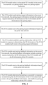
- An embodiment of the application provides a PLC-based pairing method for an air conditioner. As shown in FIG. 1 , the method includes the following operations 101 to 107.
- the CCO module selects a to-be-paired STA module in the power line network as a pairing object, based on a pairing request instruction.
- the indoor unit controller may receive a pairing request instruction sent by the wireless remote controller, and send the received pairing request instruction to the CCO module.
- a dial switch may be provided on the CCO module, and the CCO module may acquire the pairing request instruction based on the dial switch; or, the indoor unit controller may receive the pairing request instruction through a human-computer interaction module (such as key, touch screen, etc.), and send the pairing request instruction to the CCO module.
- a manner by which the CCO module acquires the pairing request instruction is not specifically limited in the application.
- the user may send a pairing request instruction to the indoor unit of the air conditioner through the wireless remote controller, the indoor unit controller sends the received pairing request instruction to the CCO module, and the CCO module starts pairing based on the acquired pairing request instruction.
- the CCO module may select a to-be-paired STA module in the power line network as a pairing object, based on the acquired pairing request instruction.
- both the CCO module on the indoor unit side of the air conditioner and the STA module on the outdoor unit side have network-wide unique identifier (ID) information
- ID information of the CCO module may be a Media Access Control (MAC) address of the outdoor unit or a Serial Number (SN) code of the outdoor unit which is uniquely identified network-wide
- the ID information of the STA module may be a MAC address of the indoor unit or a SN code of the indoor unit which is uniquely identified network-wide.
- the CCO module may acquire ID information of the to-be-paired STA module based on the power line network.
- the CCO module selects a to-be-paired STA module in a current power line network as a pairing object, and adds ID information of the selected pairing object to a pairing list such as a whitelist.
- the CCO module sends pairing request information to the power line network, the pairing request information including the pairing request instruction, ID information of the CCO module and ID information of the pairing object.
- pairing request information may be generated by the CCO module; or, the pairing request information may be generated by the indoor unit controller and sent to the CCO module, which are not specifically limited in the application.
- the CCO module generates the pairing request information based on ID information of the pairing object in the whitelist, and sends the pairing request information to the power line network, so that processing logic of the indoor unit controller may be reduced.
- the pairing request instruction may be preset coded information, which is not specifically limited in the application.
- the STA module receives the pairing request information based on the power line network.
- the STA module on the outdoor unit side may receive the pairing request information from the CCO module, based on the power line network.
- the STA module establishes a pairing relationship with the CCO module in response to determining that ID information of the STA module itself exists in the pairing request information.
- the STA module compares the ID information of the STA module itself to ID information in the pairing request information, and determines that the pairing request information is pairing request information to be received by the STA module itself when the STA module determines that the ID information of the STA module itself exists in the pairing request information; or, discards the pairing request information when the STA module determines that the ID information of the STA module itself does not exist in the pairing request information.
- the STA module may store the ID information of the CCO module in the pairing request information based on the received pairing request information, and then establish a pairing relationship with the CCO module.
- the STA module adds the ID information of the CCO module to the whitelist, that is, establishing a pairing relationship with the CCO module refers to adding the ID information of the CCO module to the whitelist.
- the STA module sends pairing feedback information to the power line network, the pairing feedback information includes a pairing success instruction, the ID information of the CCO module and the ID information of the STA module.
- the STA module determines that the pairing request information is the pairing request information to be received by the STA module itself, the STA module also sends pairing feedback information to the power line network, the pairing feedback information including a pairing success instruction, the ID information of the CCO module and the ID information of the STA module.
- pairing feedback information may be generated by the STA module; or, the pairing feedback information may be generated by the outdoor unit controller and sent to the STA module, which are not specifically limited in the application.
- the STA module may generate the pairing feedback information after determining that the pairing request information is the pairing request information to be received by the STA module itself, and sends the pairing feedback information to the power line network, so that processing logic of the outdoor unit controller may be reduced.
- the pairing success instruction may be preset coded information, which is not specifically limited in the application.
- the CCO module receives the pairing feedback information based on the power line network.
- the CCO module on the indoor unit side may receive the pairing feedback information from the STA module, based on the power line network.
- the CCO module determines that pairing is successful in response to determining that the ID information of the CCO module itself exists in the pairing feedback information, and establishes a pairing relationship with the STA module.
- the CCO module compares the ID information of the CCO module itself to ID information in the pairing feedback information, and determines that the pairing feedback information is pairing feedback information to be received by the CCO module itself when the CCO module determines that the ID information of the CCO module itself exists in the pairing feedback information; or, discards the pairing feedback information when the CCO module determines that the ID information of the CCO module itself does not exist in the pairing feedback information, so that the pairing feedback information sent by the STA module may be transmitted to the CCO module sending the pairing request information.
- the CCO module determines that pairing is successful based on the received pairing feedback information, and stores the ID information of the STA module, thereby establishing a pairing relationship with the STA module.
- the ID information of the STA module when the ID information of the STA module is stored in the whitelist at 101, it may confirm that stored information of the whitelist is correct based on the pairing feedback information at 107, thereby establishing a pairing relationship with the STA module.
- ID information of a successfully paired STA module may be stored in the whitelist at 107, thereby establishing a pairing relationship with the STA module. That is, the CCO module may be stored in the whitelist based on the ID information of the selected pairing object, or may be stored in the whitelist based on the ID information of the STA module carried in the pairing feedback information, thereby establishing a pairing relationship with the STA module.
- the CCO module may send information indicating successful pairing to the indoor unit controller after determining that pairing is successful, and the indoor unit controller may output the information indicating successful pairing through a human-computer interaction unit, for example, through a display screen, a speaker, an indicator light or the like, so that the user may know that pairing is successful.
- a human-computer interaction unit for example, through a display screen, a speaker, an indicator light or the like, so that the user may know that pairing is successful.
- paired connection between the indoor unit and the outdoor unit based on the power line network may be achieved based on establishing pairing between the CCO module of the indoor unit and the STA module of the outdoor unit.
- the CCO module transmits pairing request information to the STA module used as a pairing object based on the power line network, and the STA module establishes a pairing relationship with the CCO module based on the pairing request information; the STA module transmits pairing feedback information to the CCO module based on the power line network, and the CCO module determines that pairing is successful based on the pairing feedback information, and establishes a pairing relationship with the STA module.
- the method implements establishing a pairing relationship between the CCO module on the indoor unit side and the STA module on the outdoor unit side, so that paired connection between the indoor unit and the outdoor unit of the air conditioner may be achieved based on the power line network without aid of additional pairing devices, installation and debugging according to the method are simple, so that cost of pairing between the indoor unit and the outdoor unit of the air conditioner may be saved.
- the method further includes the following operations.
- An indoor unit controller of the indoor unit sends a test instruction to a paired outdoor unit in response to successful pairing of the CCO module, and the test instruction is sequentially transmitted by the CCO module, the power line network and the STA module to an outdoor unit controller of the outdoor unit.
- the indoor unit controller may send a test instruction to an outdoor unit controller of the paired outdoor unit, the test instruction may be sequentially transmitted by the CCO module on the indoor unit side, the power line network and the STA module on the paired outdoor unit side to the outdoor unit controller of the outdoor unit.
- the paired CCO module and STA module constitute a communication network based on the power line network, which may transmit the test instruction.
- the test instruction may be an instruction of controlling startup and operation of the outdoor unit.
- An operator may observe whether a compressor and/or fan of an outdoor unit which requires pairing actually is started, to determine whether the established pairing relationship is correct.
- the outdoor unit which requires pairing actually is not successfully started, it may be determined that the established pairing relationship is erroneous, that is, pairing between the outdoor unit and the indoor unit is erroneous.
- the method further includes the following operations when the pairing between the outdoor unit and the indoor unit is erroneous.
- the outdoor unit receives a pairing removal instruction, and the STA module removes stored ID information based on the pairing removal instruction.
- the indoor unit receives the pairing request instruction, and the CCO module restarts pairing based on the pairing request instruction.
- an input module such as a dial switch, a key, or the like may be provided on the outdoor unit side to input the pairing removal instruction.
- a key or a dial switch is provided on the outdoor unit controller to input the pairing removal instruction; or, a dial switch is provided on the STA module to input the pairing removal instruction, etc.
- the dial switch refers to an address switch operated and controlled based on a binary coding principle of 0/1, and may also be referred to as a DIP switch, a toggling switch, an address switch, a stirring switch, a digital switch, a finger-toggling switch, etc.
- the operator may input the pairing removal instruction based on the input module on the outdoor unit side, and the STA module may remove the stored ID information based on the pairing removal instruction, that is, the STA module may clear the whitelist and release the bound CCO module.
- the operator may also re-send a pairing request instruction to the indoor unit controller through the wireless remote controller, the indoor unit controller sends the pairing request instruction to the CCO module, and the CCO module restarts pairing based on the pairing request instruction.
- the method further includes the following operations.
- the CCO module determines that pairing fails in response to no confirmation on successful pairing of a current pairing request information within a set time period.
- the CCO module determines that pairing fails when the CCO module does not receive pairing feedback information required to be received by the CCO module itself within the set time period, and sends information indicating failed pairing to an indoor unit master controller.
- the method further includes the following operations.
- An indoor unit controller of the indoor unit sends the pairing request instruction to the CCO module to restart pairing, in response to failed pairing of the CCO module.
- the indoor unit controller may re-send the pairing request instruction to the CCO module to restart pairing.
- the PLC-based pairing method for the air conditioner is exemplified below in combination with an application example.
- the pairing method includes the following operations 201 to 210.
- a remote controller sends a pairing request instruction.
- the user may send a pairing request instruction to the indoor unit of the air conditioner through the wireless remote controller, and the indoor unit controller receives the pairing request instruction.
- the indoor unit controller displays a pairing ID and sends the pairing request instruction to the CCO module.
- the indoor unit controller may display the pairing ID on the display screen to indicate that the indoor unit is in a pairing state at present, and send the pairing request instruction to the CCO module.
- the pairing ID may be text information or light indication information, which is not specifically limited in the application.
- the CCO module adds the STA module in the power line network to the whitelist.
- the CCO module may select a to-be-paired STA module in the power line network as a pairing object based on the acquired pairing request instruction, and add ID information of the pairing object to the whitelist.
- the ID information of the pairing object may be a MAC address of the outdoor unit where the STA module is located.
- the STA module adds the CCO module in the power line network to the whitelist.
- the CCO module generates pairing request information based on ID information of the pairing object in the whitelist, and sends the pairing request information to the power line network
- the pairing request information may include the pairing request instruction, ID information of the CCO module and the ID information of the pairing object.
- the ID information of the CCO module may be a MAC address of the indoor unit where the CCO module is located.
- the STA module may receive the pairing request information from the CCO module based on the power line network.
- the STA module compares the ID information of the STA module itself to ID information in the pairing request information, and determines that the pairing request information is pairing request information to be received by the STA module itself when the STA module determines that the ID information of the STA module itself exists in the pairing request information; or, discards the pairing request information when the STA module determines that the ID information of the STA module itself does not exist in the pairing request information.
- the STA module may store the ID information of the CCO module in the pairing request information based on the received pairing request information, that is, add the ID information of the CCO module to the whitelist.
- the indoor unit controller determines whether pairing is successful, and operation 206 is executed when pairing is unsuccessful; otherwise, operation 207 is executed.
- the STA module determines that the pairing request information is the pairing request information to be received by the STA module itself, the STA module also sends pairing feedback information to the power line network, the pairing feedback information includes a pairing success instruction, the ID information of the CCO module and the ID information of the STA module.
- the CCO module compares the ID information of the CCO module itself to ID information in the pairing feedback information, and determines that the pairing feedback information is the pairing feedback information to be received by the CCO module itself when the CCO module determines that the ID information of the CCO module itself exists in the pairing feedback information; or, discards the pairing feedback information when the CCO module determines that the ID information of the CCO module itself does not exist in the pairing feedback information, so that the pairing feedback information sent by the STA module may be transmitted to the CCO module sending the pairing request information.
- the CCO module determines that pairing fails when the CCO module does not receive pairing feedback information required to be received by the CCO module itself within the set time period, and sends information indicating failed pairing to an indoor unit master controller.
- the CCO module determines that pairing is successful based on the received pairing feedback information, and sends information indicating successful pairing to the indoor unit controller.
- the indoor unit controller may determine whether pairing is successful based on the information fed back by the CCO module, and operation 206 is executed when pairing is unsuccessful; otherwise, operation 207 is executed.
- the indoor unit displays that pairing fails, and the process returns to 201.
- the display module of the indoor unit may display information indicating failed pairing, and the process returns to 201 to restart pairing.
- the indoor unit displays that pairing is successful.
- the display module of the indoor unit may display information indicating successful pairing.
- operation 209 is executed when the bound outdoor unit is not a corresponding outdoor unit; otherwise, operation 210 is executed.
- the indoor unit controller may send a test instruction to an outdoor unit controller of the paired outdoor unit, the test instruction may be sequentially transmitted by the CCO module on the indoor unit side, the power line network and the STA module on the paired outdoor unit side to the outdoor unit controller of the outdoor unit.
- the test instruction may be an instruction of controlling startup and operation of the outdoor unit.
- the operator may observe whether a compressor and/or fan of an outdoor unit which requires pairing actually is started, to determine whether the established pairing relationship is correct.
- the outdoor unit which requires pairing actually is not successfully started, it may be determined that the established pairing relationship is erroneous, that is, pairing between the outdoor unit and the indoor unit is erroneous.
- the outdoor unit triggers unbinding, and the process returns to 201.
- the operator may manually input a removal instruction on the input module on the outdoor unit side.
- a pairing removal instruction is input based on the input module of the outdoor unit controller, and the STA module remove the stored ID information based on the pairing removal instruction, that is, the STA module clears the whitelist and releases the bound CCO module.
- the process returns to 201 to restart pairing.
- pairing is completed, and the pairing process is exited.
- pairing may be directly made based on the CCO module and the STA module in the power line network, without aid of additional pairing devices, installation and debugging according to the method are simple, so that cost of pairing between the indoor unit and the outdoor unit of the air conditioner may be saved.
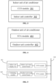
- An embodiment of the application further provides an indoor unit of an air conditioner.
- the indoor unit includes a CCO module 301, the CCO module 301 is coupled and connected to a power line network, and is configured to:
- the indoor unit further includes an indoor unit controller 302, the indoor unit controller 302 is connected in communication with the CCO module 301, and is configured to send a test instruction to a paired outdoor unit in response to successful pairing of the CCO module, the test instruction is sequentially transmitted by the CCO module, the power line network and the STA module to an outdoor unit controller of the outdoor unit.
- the indoor unit controller 302 is connected in communication with the CCO module 301, and is configured to send a test instruction to a paired outdoor unit in response to successful pairing of the CCO module, the test instruction is sequentially transmitted by the CCO module, the power line network and the STA module to an outdoor unit controller of the outdoor unit.
- the indoor unit controller 302 when pairing between the outdoor unit and the indoor unit is erroneous, the indoor unit controller 302 further receives the pairing request instruction, and the CCO module 301 is further configured to restart pairing based on the pairing request instruction.
- the CCO module 301 is further configured to determine that pairing fails in response to no confirmation on successful pairing of a current pairing request information within a set time period.
- the indoor unit controller 302 is further configured to send the pairing request instruction to the CCO module 301 to restart pairing, in response to failed pairing of the CCO module 301.
- An embodiment of the application further provides an outdoor unit of an air conditioner.
- the outdoor unit includes a STA module 401, the STA module 401 is coupled and connected to a power line network, and is configured to:
- the STA module 401 is further configured to remove stored ID information based on a pairing removal instruction.
- the outdoor unit includes an outdoor unit controller 402, an input module is provided on the outdoor unit controller 402, and the operator may input a pairing removal instruction through the input module when it is determined that pairing between the outdoor unit and the indoor unit is erroneous, and the outdoor unit controller 402 sends the pairing removal instruction to the STA module 401.
- the input module may be a key or a dial switch.
- An embodiment of the application further provides an air conditioner.
- the air conditioner includes an indoor unit 501 and an outdoor unit 502 connected to a power line network 503.
- the indoor unit 501 and the indoor unit 502 are configured to execute operations of the method according to the foregoing embodiments of the application when the outdoor unit and the indoor unit run a computer program. Details may refer to descriptions of the foregoing method embodiments, and are not elaborated here.
- the air conditioner is configured to adjust temperature, humidity, or the like of the environment where the air conditioner is located.
- the air conditioner may be a single-refrigerating air conditioner or a dual-purpose air conditioner, and may be a wall-mounted air conditioner, a vertical cabinet air conditioner, a window-mounted air conditioner, a ceiling-mounted air conditioner, or other forms of air conditioners, which are not specifically limited in the embodiment of the application.
- the air conditioner according to the embodiment of the application may be an independent air conditioner of which indoor units correspond to outdoor units one-to-one.
- the indoor unit 501 includes an indoor unit main control board, a CCO module and an indoor unit display box (equivalent to a display module), the indoor unit display box and the CCO module are connected to the indoor unit main control board, and the CCO module is coupled to the power line network.
- the outdoor unit 502 includes an outdoor unit main control board, a STA module and an unbinding module (equivalent to an input module), the unbinding module and the STA module are connected to the outdoor unit main control board, and the STA module is connected to the power line network.
- an embodiment of the application further provides a storage medium, i.e., a computer storage medium.
- the storage medium may be a computer-readable storage medium, for example, including a memory having stored thereon a computer program, and the computer program may be executed by a processor of the air conditioner to implement operations of the method according to the embodiments of the application.
- the computer-readable storage medium may be a Read Only Memory (ROM), a Programmable Read-Only Memory (PROM), an Erasable Programmable Read-Only Memory (EPROM), an Electrically Erasable Programmable Read-Only Memory (EEPROM), a flash memory, a magnetic surface memory, an optical disk, a Compact Disc Read-Only Memory (CD-ROM), or other memories.
Landscapes
- Engineering & Computer Science (AREA)
- Signal Processing (AREA)
- Chemical & Material Sciences (AREA)
- Combustion & Propulsion (AREA)
- Mechanical Engineering (AREA)
- General Engineering & Computer Science (AREA)
- Power Engineering (AREA)
- Computer Networks & Wireless Communication (AREA)
- Human Computer Interaction (AREA)
- Physics & Mathematics (AREA)
- Fuzzy Systems (AREA)
- Mathematical Physics (AREA)
- Air Conditioning Control Device (AREA)
- Selective Calling Equipment (AREA)
Applications Claiming Priority (2)
| Application Number | Priority Date | Filing Date | Title |
|---|---|---|---|
| CN202110483060.3A CN113203190B (zh) | 2021-04-30 | 2021-04-30 | 空调器基于电力线通讯的配对方法、装置和存储介质 |
| PCT/CN2021/118989 WO2022227377A1 (zh) | 2021-04-30 | 2021-09-17 | 空调器基于电力线通讯的配对方法、装置和存储介质 |
Publications (2)
| Publication Number | Publication Date |
|---|---|
| EP4328511A1 true EP4328511A1 (de) | 2024-02-28 |
| EP4328511A4 EP4328511A4 (de) | 2024-10-16 |
Family
ID=77028223
Family Applications (1)
| Application Number | Title | Priority Date | Filing Date |
|---|---|---|---|
| EP21938841.0A Pending EP4328511A4 (de) | 2021-04-30 | 2021-09-17 | Stromleitungskommunikationsbasiertes paarungsverfahren und -vorrichtung für klimaanlage und speichermedium |
Country Status (4)
| Country | Link |
|---|---|
| US (1) | US12435896B2 (de) |
| EP (1) | EP4328511A4 (de) |
| CN (1) | CN113203190B (de) |
| WO (1) | WO2022227377A1 (de) |
Families Citing this family (4)
| Publication number | Priority date | Publication date | Assignee | Title |
|---|---|---|---|---|
| CN113203190B (zh) * | 2021-04-30 | 2022-05-27 | 佛山市顺德区美的电子科技有限公司 | 空调器基于电力线通讯的配对方法、装置和存储介质 |
| CN113566390A (zh) * | 2021-08-06 | 2021-10-29 | 广东美的制冷设备有限公司 | 空调系统的组网方法、空调系统、空调设备和存储介质 |
| CN113839997A (zh) * | 2021-09-17 | 2021-12-24 | 四川长虹空调有限公司 | 一种空调机的设备信息获取方法及空调机 |
| CN118400204B (zh) * | 2024-06-28 | 2024-08-23 | 广东信通通信有限公司 | 基于电力双模载波的传感器白名单远程管理方法及系统 |
Family Cites Families (22)
| Publication number | Priority date | Publication date | Assignee | Title |
|---|---|---|---|---|
| JP3858154B2 (ja) * | 2003-10-23 | 2006-12-13 | 株式会社日立製作所 | 空調システム |
| JP4846621B2 (ja) * | 2007-02-28 | 2011-12-28 | シャープ株式会社 | 通信装置およびプログラム |
| FR2980060B1 (fr) * | 2011-09-13 | 2013-10-04 | Voltalis | Optimisation d'un systeme domotique utilisant un reseau local de courant porteur de ligne |
| CN103954011B (zh) * | 2014-05-07 | 2017-10-03 | 珠海格力电器股份有限公司 | 空调机组的室内、外机匹配方法和装置以及空调机组 |
| CN104776562B (zh) | 2015-04-14 | 2017-10-31 | 广东美的暖通设备有限公司 | 多联机系统及内外机通过电力线载波通讯建立连接的方法 |
| CN106533501A (zh) * | 2015-09-14 | 2017-03-22 | 深圳市中兴微电子技术有限公司 | 电力线通信网络的站点间通信状态检测方法及装置 |
| CN105953370B (zh) * | 2016-05-18 | 2019-01-01 | 珠海格力电器股份有限公司 | 多联空调机组及其内外机的自动匹配方法和装置 |
| CN106210170B (zh) * | 2016-07-18 | 2019-01-29 | 珠海格力电器股份有限公司 | 一种多联空调机组网络的内机地址确定装置及方法 |
| CN108696298B (zh) * | 2017-04-10 | 2020-11-17 | 华为技术有限公司 | 数据传输方法及装置、电力线通信网络、电力系统 |
| US12422157B2 (en) * | 2017-06-16 | 2025-09-23 | Copeland Comfort Control Lp | Wirelessly configuring climate control system controls |
| KR102393277B1 (ko) * | 2017-08-24 | 2022-05-03 | 삼성전자주식회사 | 에어컨 중계기, 에어컨 시스템 및 에어컨 시스템 제어 방법 |
| CN108541055B (zh) | 2018-03-02 | 2019-09-20 | 珠海格力电器股份有限公司 | 功率调整方法及装置、基于电力线载波的功率调整方法 |
| CN108386968B (zh) * | 2018-03-08 | 2020-07-10 | 上海物麒科技有限公司 | 多联机空调通过设备唯一编码与物理地址实现的组网方法 |
| CN108266861B (zh) * | 2018-03-08 | 2023-11-28 | 重庆物奇科技有限公司 | 通过识别卡进行配对组网的多联机空调系统及其组网方法 |
| CN108386965B (zh) * | 2018-03-08 | 2020-09-04 | 上海物麒科技有限公司 | 通过设备唯一编码配对和识别卡配对的plc组网方法 |
| US20190309977A1 (en) * | 2018-04-04 | 2019-10-10 | Johnson Controls Technology Company | Systems and methods for dynamically generating barcodes for thermostat installation |
| US20190309971A1 (en) * | 2018-04-04 | 2019-10-10 | Johnson Controls Technology Company | Systems and methods for dynamically generating barcodes to identify hvac system faults |
| CN108488914A (zh) * | 2018-04-13 | 2018-09-04 | 珠海格力电器股份有限公司 | 空调机组、空调机组的操作方法和装置 |
| CN108592302B (zh) * | 2018-04-13 | 2021-04-30 | 珠海格力电器股份有限公司 | 数据的发送方法,装置,多联机系统,存储介质 |
| CN108800455B (zh) * | 2018-04-13 | 2023-06-06 | 珠海格力电器股份有限公司 | 空调机组、空调机组的控制方法和中央协调器 |
| CN110430293B (zh) * | 2019-08-06 | 2021-01-12 | 珠海格力电器股份有限公司 | 多联机系统的配对方法及装置、存储介质和处理器 |
| CN113203190B (zh) * | 2021-04-30 | 2022-05-27 | 佛山市顺德区美的电子科技有限公司 | 空调器基于电力线通讯的配对方法、装置和存储介质 |
-
2021
- 2021-04-30 CN CN202110483060.3A patent/CN113203190B/zh active Active
- 2021-09-17 WO PCT/CN2021/118989 patent/WO2022227377A1/zh not_active Ceased
- 2021-09-17 EP EP21938841.0A patent/EP4328511A4/de active Pending
-
2023
- 2023-10-27 US US18/384,503 patent/US12435896B2/en active Active
Also Published As
| Publication number | Publication date |
|---|---|
| CN113203190A (zh) | 2021-08-03 |
| US12435896B2 (en) | 2025-10-07 |
| CN113203190B (zh) | 2022-05-27 |
| WO2022227377A1 (zh) | 2022-11-03 |
| EP4328511A4 (de) | 2024-10-16 |
| US20240053041A1 (en) | 2024-02-15 |
Similar Documents
| Publication | Publication Date | Title |
|---|---|---|
| US12435896B2 (en) | Power line communication-based pairing method and device for air conditioner, and storage medium | |
| CN108386968B (zh) | 多联机空调通过设备唯一编码与物理地址实现的组网方法 | |
| JP2015121392A (ja) | 空気調和システム | |
| JP6051089B2 (ja) | 空調システム | |
| JPWO2008035402A1 (ja) | 空気調和システム | |
| CN101135903A (zh) | 一种电器远程控制系统 | |
| CN113587391A (zh) | 一种基于蓝牙通信的多联机系统 | |
| CN113300738A (zh) | 跨相通讯器、通讯方法、系统及存储介质 | |
| WO2015033596A1 (ja) | 空調システム | |
| JPWO2019239830A1 (ja) | 空調システム | |
| EP1657639A1 (de) | Aktualisierungssystem und -verfahren für eine Ausseneinheitssoftware | |
| JP5316477B2 (ja) | 空調制御装置 | |
| CN113203189B (zh) | 空调器基于电力线通讯的配对方法、装置和存储介质 | |
| CN104730977A (zh) | 一种存储和读取空调容量码的方法及空调 | |
| EP3139543B1 (de) | Addresszuweisung in einem klimaanlagensystem | |
| JP5774178B2 (ja) | 通信アダプタ、通信方法、及び、プログラム | |
| JP2000101578A (ja) | 無線ネットワークシステム | |
| CN111964222B (zh) | 空调控制方法和装置、设备及存储介质 | |
| CN113218041B (zh) | 空调器基于电力线通讯的配对方法、装置和存储介质 | |
| JPWO2019069481A1 (ja) | 制御システムおよび制御プログラム | |
| CN115550159A (zh) | 一种设备入网方法和线控器 | |
| JP7468152B2 (ja) | 空調機システム | |
| CN113531775B (zh) | 空调器的内外机配对故障定位方法、空调器和存储介质 | |
| CN113757927B (zh) | 空调设备 | |
| CN117537454A (zh) | 空调器的通信方式确定方法、控制器、空调器及存储介质 |
Legal Events
| Date | Code | Title | Description |
|---|---|---|---|
| STAA | Information on the status of an ep patent application or granted ep patent |
Free format text: STATUS: THE INTERNATIONAL PUBLICATION HAS BEEN MADE |
|
| PUAI | Public reference made under article 153(3) epc to a published international application that has entered the european phase |
Free format text: ORIGINAL CODE: 0009012 |
|
| STAA | Information on the status of an ep patent application or granted ep patent |
Free format text: STATUS: REQUEST FOR EXAMINATION WAS MADE |
|
| 17P | Request for examination filed |
Effective date: 20231120 |
|
| AK | Designated contracting states |
Kind code of ref document: A1 Designated state(s): AL AT BE BG CH CY CZ DE DK EE ES FI FR GB GR HR HU IE IS IT LI LT LU LV MC MK MT NL NO PL PT RO RS SE SI SK SM TR |
|
| DAV | Request for validation of the european patent (deleted) | ||
| DAX | Request for extension of the european patent (deleted) | ||
| A4 | Supplementary search report drawn up and despatched |
Effective date: 20240917 |
|
| RIC1 | Information provided on ipc code assigned before grant |
Ipc: F24F 11/62 20180101ALI20240911BHEP Ipc: H04B 3/54 20060101ALI20240911BHEP Ipc: F24F 11/56 20180101ALI20240911BHEP Ipc: F24F 11/50 20180101AFI20240911BHEP |
|
| STAA | Information on the status of an ep patent application or granted ep patent |
Free format text: STATUS: EXAMINATION IS IN PROGRESS |
|
| 17Q | First examination report despatched |
Effective date: 20251210 |