EP4328543B1 - Procédé d'évaluation du résultat d'un traitement de surface effectué sur une pièce par jets de particules - Google Patents
Procédé d'évaluation du résultat d'un traitement de surface effectué sur une pièce par jets de particules Download PDFInfo
- Publication number
- EP4328543B1 EP4328543B1 EP22191729.7A EP22191729A EP4328543B1 EP 4328543 B1 EP4328543 B1 EP 4328543B1 EP 22191729 A EP22191729 A EP 22191729A EP 4328543 B1 EP4328543 B1 EP 4328543B1
- Authority
- EP
- European Patent Office
- Prior art keywords
- particle
- measuring
- workpiece
- determined
- level
- Prior art date
- Legal status (The legal status is an assumption and is not a legal conclusion. Google has not performed a legal analysis and makes no representation as to the accuracy of the status listed.)
- Active
Links
Images



Classifications
-
- G—PHYSICS
- G01—MEASURING; TESTING
- G01B—MEASURING LENGTH, THICKNESS OR SIMILAR LINEAR DIMENSIONS; MEASURING ANGLES; MEASURING AREAS; MEASURING IRREGULARITIES OF SURFACES OR CONTOURS
- G01B11/00—Measuring arrangements characterised by the use of optical techniques
- G01B11/30—Measuring arrangements characterised by the use of optical techniques for measuring roughness or irregularity of surfaces
- G01B11/303—Measuring arrangements characterised by the use of optical techniques for measuring roughness or irregularity of surfaces using photoelectric detection means
-
- G—PHYSICS
- G01—MEASURING; TESTING
- G01N—INVESTIGATING OR ANALYSING MATERIALS BY DETERMINING THEIR CHEMICAL OR PHYSICAL PROPERTIES
- G01N21/00—Investigating or analysing materials by the use of optical means, i.e. using sub-millimetre waves, infrared, visible or ultraviolet light
- G01N21/84—Systems specially adapted for particular applications
- G01N21/88—Investigating the presence of flaws or contamination
- G01N21/95—Investigating the presence of flaws or contamination characterised by the material or shape of the object to be examined
- G01N21/956—Inspecting patterns on the surface of objects
- G01N21/95607—Inspecting patterns on the surface of objects using a comparative method
-
- B—PERFORMING OPERATIONS; TRANSPORTING
- B24—GRINDING; POLISHING
- B24C—ABRASIVE OR RELATED BLASTING WITH PARTICULATE MATERIAL
- B24C1/00—Methods for use of abrasive blasting for producing particular effects; Use of auxiliary equipment in connection with such methods
- B24C1/10—Methods for use of abrasive blasting for producing particular effects; Use of auxiliary equipment in connection with such methods for compacting surfaces, e.g. shot-peening
-
- G—PHYSICS
- G01—MEASURING; TESTING
- G01B—MEASURING LENGTH, THICKNESS OR SIMILAR LINEAR DIMENSIONS; MEASURING ANGLES; MEASURING AREAS; MEASURING IRREGULARITIES OF SURFACES OR CONTOURS
- G01B11/00—Measuring arrangements characterised by the use of optical techniques
- G01B11/28—Measuring arrangements characterised by the use of optical techniques for measuring areas
- G01B11/285—Measuring arrangements characterised by the use of optical techniques for measuring areas using photoelectric detection means
-
- G—PHYSICS
- G01—MEASURING; TESTING
- G01B—MEASURING LENGTH, THICKNESS OR SIMILAR LINEAR DIMENSIONS; MEASURING ANGLES; MEASURING AREAS; MEASURING IRREGULARITIES OF SURFACES OR CONTOURS
- G01B11/00—Measuring arrangements characterised by the use of optical techniques
- G01B11/24—Measuring arrangements characterised by the use of optical techniques for measuring contours or curvatures
-
- G—PHYSICS
- G01—MEASURING; TESTING
- G01B—MEASURING LENGTH, THICKNESS OR SIMILAR LINEAR DIMENSIONS; MEASURING ANGLES; MEASURING AREAS; MEASURING IRREGULARITIES OF SURFACES OR CONTOURS
- G01B9/00—Measuring instruments characterised by the use of optical techniques
- G01B9/02—Interferometers
- G01B9/0209—Low-coherence interferometers
-
- G—PHYSICS
- G01—MEASURING; TESTING
- G01N—INVESTIGATING OR ANALYSING MATERIALS BY DETERMINING THEIR CHEMICAL OR PHYSICAL PROPERTIES
- G01N21/00—Investigating or analysing materials by the use of optical means, i.e. using sub-millimetre waves, infrared, visible or ultraviolet light
- G01N21/84—Systems specially adapted for particular applications
- G01N2021/8411—Application to online plant, process monitoring
-
- G—PHYSICS
- G01—MEASURING; TESTING
- G01N—INVESTIGATING OR ANALYSING MATERIALS BY DETERMINING THEIR CHEMICAL OR PHYSICAL PROPERTIES
- G01N21/00—Investigating or analysing materials by the use of optical means, i.e. using sub-millimetre waves, infrared, visible or ultraviolet light
- G01N21/84—Systems specially adapted for particular applications
- G01N21/88—Investigating the presence of flaws or contamination
- G01N21/95—Investigating the presence of flaws or contamination characterised by the material or shape of the object to be examined
- G01N21/956—Inspecting patterns on the surface of objects
- G01N21/95607—Inspecting patterns on the surface of objects using a comparative method
- G01N2021/95615—Inspecting patterns on the surface of objects using a comparative method with stored comparision signal
Definitions
- the present invention relates to methods for assessing the result of a surface treatment carried out on a workpiece by particle blasting. This is used, for example, in the aviation and/or automotive industries.
- the invention relates to a method for automatically checking the coverage of particle-blasted, e.g. shot-blasted, surfaces.
- the US 5293320 A The aim is to create a surface map by measuring the surface line by line using tactile measurements. In elevation sections of this surface map, contours, comparable to contour lines on maps, are searched for and classified. The degree of coverage is determined based on the number and type of these contours.
- a correlation analysis is carried out on two ideally parallel line tracings of the surface to be tested.
- High correlation values are due to regular surface geometries such as turning grooves.
- Low correlation values indicate random surface geometries, such as those caused by shot peening, show high degrees of coverage.
- the DE 102010001286 A1 suggests taking a 3D surface image using a white light interferometer or confocal microscope and then determining the local heights caused by blasting by subtracting the determined component shape from a known surface geometry of the untreated workpiece. Heights that are below the zero line are identified as impacts. The degree of coverage is then determined based on their surface area.
- the proposed approach creates a 3D depth map from photographic images of the blasted surface under different illumination directions. Deep areas whose variation is greater than or equal to 10% of the global variation in the image are identified as impact craters.
- the JP 2010017807 A proposes determining the degree of coverage by analyzing the height distribution of the individual points, although it is not specified which measuring instrument should be used to make this determination.
- the Gaussian distributions of the heights of blasted and non-blasted surfaces have different widths and mean values; the measured height distribution is broken down into these two components and the proportions of the surface are determined using the integrals under the distributions.
- images of the surface are taken using a telecentric lens with a spacer.
- Coaxial illumination is achieved using a beam splitter with an LED mounted orthogonally to the optical axis.
- the impacts are identified using the method according to the JP 5511407 B2 using a simple threshold value of brightness, the area calculation by counting pixels.
- the degree of coverage is determined by the average luminance (as the arithmetic mean of all pixel brightnesses) and corresponding calibration functions for the surface to be illuminated.
- the DE 102020108956 A1 proposes the recording of at least one impact geometry in order to calculate at least one quality parameter.
- the blasting process is to be controlled on the basis of this.
- the detection system is described as an optical one, preferably based on the principle of white light interferometry.
- the detection system should be able to communicate with the blasting system control system with the possible assistance of a digital computer. No further details are given on the structure, algorithms or procedure.
- Tactile surface measurement is time-consuming and is usually carried out on measuring machines with limited measuring space and inflexible positioning of the probe tip. This makes testing large or irregularly shaped parts difficult or impossible. Furthermore, the radius of the measuring tip usually means that error-free scanning of the very irregular blasted surface is not possible.
- Photographic recordings usually require strict and complex control of the lighting conditions. Deviations from these conditions as well as irregularities and contamination on the components to be tested lead to unreliable results.
- the common automatic methods generally have in common that they directly determine the covered portion of the surface. Based on the usual definition of 98% coverage as "completely blasted" in practice, an error of 1% in determining the corresponding area leads to a falsification of the measurement result by 0.98%.
- This invention aims to remedy this situation.
- the surface treated by particle blasting is recorded with spatial resolution using an optical measuring method.
- this is done with a high resolution.
- the resolution should be selected so that an average impact has at least ten image points in width and/or length, preferably at least twenty. For the smallest particles used in practice, this would mean a lateral minimum resolution of 7 ⁇ m , and for the largest particles 0.13mm.
- the height resolution should ideally be at least five times, in particular at least ten times, as good as the lateral minimum resolution specified above, in particular the lateral resolution used.
- a lateral resolution of 5 ⁇ m or better and/or a height resolution of ⁇ 1 ⁇ m can be used in one or two lateral directions.
- the height is recorded with spatial resolution.
- a surface level and a value of a local gradient are determined in relation to neighboring measurement points.
- a surface level refers to a spatial position of the surface point in relation to a reference point, e.g. to a predefined origin point or to an origin plane in the workpiece itself. The surface level therefore indicates a value for the height of the surface at the location of the respective measurement point.
- the detected surface level is compared with a target level expected for the untreated workpiece at the measuring location of the measuring point, and a deviation is determined.
- the expected target level can be derived, for example, in particular from a design model of the workpiece, but also from a measurement of the workpiece before treatment by means of particle blasting.
- those measuring points for which both the surface level recorded according to the invention is above a level that is lower than the target level by a predetermined height threshold are then classified as If the slope recorded also falls below a predetermined slope threshold, the measurement points are identified as those not hit by a particle of the particle beam.
- White light interferometry can be used advantageously as an optical measuring method.
- This measuring method has proven to be particularly robust and not susceptible to interference, especially with regard to possible scattered light. At the same time, it can create high-resolution images of the treated surface with good spatial and height resolution.
- the method is advantageously carried out for a plurality of sections of the same surface, which are in particular disjoint.
- the sections are each recorded with spatial resolution, i.e. in particular the height in the sections is recorded with spatial resolution.
- the sections are in particular rectangular or square.
- the sections are arranged on a surface or along a line.
- the number of sections is between 10 and 500.
- the sections each have a size in the range of 10x10mm to 100x100mm.
- the sections are spaced apart from one another in the range of 1mm to 100mm and/or span a distance in the range of 5mm to 300mm and/or an area in the range of 10x10mm to 50x100mm.
- the sections are arranged equidistantly and/or regularly on the line and/or surface. This allows a particularly representative coverage to be determined with the least possible effort.
- the evaluation described above is typically carried out computer-aided, using software that carries out the evaluation. This can then archive the evaluation results, possibly together with the raw data, e.g. the surface images, associated with the workpiece, as a kind of quality pass.
- the deformation of the surface depends on both the material of the workpiece and the parameters of the particle blasting process, such as in particular the geometric shape and size / size distribution of the particles, their material, such as glass, ceramic, steel or the like, as well as the speed of the particle beam, which determines the momentum and energy of the particles when they hit the surface of the workpiece, very different and individual impact patterns and geometries of the blasted workpiece result. Due to this, the values for the height threshold and also the slope threshold must be determined for a given combination of workpiece and blasting parameters or approximately derived from a large database. If the ratio of diameter to depth of the impact caps remains similar, height thresholds and also the slope thresholds obtained with other parameters can be used without any problems.
- the height threshold value to be used and the gradient threshold value to be used with the most similar ratio of diameter to depth of the impact caps or an interpolation or a weighted average of the height threshold values and the gradient threshold values with the most similar ratios of diameter to depth of the impact caps are used.
- the values for the height threshold and/or the gradient threshold can preferably be determined on the basis of an analysis of a reference pattern processed with a specific particle beam with specified particles and beam parameters and/or a simulation model of a processing pattern created for such a processing process and/or determined on the basis of analyses of a large number of reference samples processed with different particle beams (each with specified particles and beam parameters) and/or simulation models of processing patterns created for such processing operations.
- the threshold values can be determined using statistical methods based on the height and gradient distribution in images of blasted surfaces on reference workpieces, ideally but not necessarily with little coverage. However, it can also be determined based on considerations of the The deformations expected from impacts and induced residual compressive stresses can be derived from a simulation.
- the threshold values can be understood, for example, as coordinates in a two-dimensional parameter space consisting of local height and local slope, with the measured coverage CR G ( Z , Z ') forming the response variable.
- the mean value of the measured coverage CR ⁇ ,i ( Z,Z' ) including the standard deviation ⁇ i (Z,Z') can be determined over the parameter space for several actual coverage levels (e.g. 60%, 80% and 100%) using several samples. The differences in the mean values of the measured coverage level between two differently covered sample groups (over the parameter space) are then determined and then normalized with the sum of the respective local standard deviations. This results in a representation of the discrimination ability Sig ( Z,Z' ) achievable with different threshold combinations over the parameter space.
- Sig Z , Z ′ CR G ⁇ ,1 Z , Z ′ ⁇ CR G ⁇ ,2 Z , Z ′ ⁇ 1 Z , Z ′ + ⁇ 2 Z , Z ′
- the result is given in standard deviations at the achievable distance between the measured values, which can be used to easily select optimal threshold combinations.
- the connection between the measured and actual coverage can be established using a correlation function or look-up table, for example.
- a separate, particularly predetermined, threshold can be used to distinguish between good and bad parts, i.e. those with sufficient and those with insufficient coverage.
- the present invention can generally be assigned to the fields of testing technology, in particular automatic testing technology, and optical measuring technology for quality assurance. It preferably uses the optical measuring method of white light interferometry for high-resolution, flat recording of particle-blasted surfaces.
- the preferred use of a collaborative robot (cobot) to guide the optical measuring instrument, such as a white light interferometer, enables both automatic positioning and measurement as well as manual guidance.
- the surface data obtained is then digitally processed.
- a high-resolution 3D point cloud of the surface to be tested can be generated, for example, by means of a measuring instrument guided by a collaborative robot (cobot).
- a white light interferometer can preferably be used here.
- other methods for 3D surface measurement are also suitable.
- a laser targeting device consisting of a cross and a point laser can be used. The lasers can be positioned and aligned on the measuring device in such a way that the center of the cross and the point lie on top of one another at a tool center point of the measuring device. This makes it particularly easy for an operator to handle the measuring device and align it for the measurement.
- the images of the workpiece surface to be inspected can be taken, for example, using a measuring head of a white light interferometer mounted on a cobot, e.g. the CRX10IAL-30P-V-PN/0 model from FANUC.
- the cobot can be arranged on a movable table, for example.
- the necessary robot control and a computer for evaluating the images can be arranged on the table.
- the top of the table can also serve as a storage area for the components to be inspected. In places with increased vibrations, it may be necessary to mount such a table on dampers.
- the measuring head can be attached to a flange of the robot with a white light interferometer, e.g. the H6 model from Heliotis.
- the interferometer can be aligned either parallel or orthogonal to the axis of rotation of the flange.
- the measuring head can also contain a cross and a point laser, which form a targeting device.
- the lasers can be aligned so that the point and the center of the cross are aligned in the tool center point of the interferometer.
- the positioning of the measuring head can be done automatically by the robot or using the manual guidance function. If a recording is now triggered, the data is transferred to the computer and evaluated.
- the interferometer must not exceed a maximum tilt relative to the surface normal of the workpiece during recording.
- the maximum permissible tilt depends on both the exact surface geometry and the required accuracy.
- Implausible measurement points and noise can then be removed using a statistical outlier filter. It is possible to replace missing points with plausible values using a modified Gaussian filter.
- the theoretical surface of the component can then be determined in the point clouds prepared in this way using a fitting algorithm. Alternatively, it is possible to use the theoretical surface from a design project for the production of the component. Now the local heights of the points can be determined either by calculating the geometric distance to the theoretical surface or by subtracting the Z value of the same at the same X and Y coordinates. From the heights determined in this way, the local gradients can now be calculated, e.g. using a Sobel operator. All points that are above the height threshold and simultaneously below the gradient threshold are identified as part of the uncovered surface.
- the threshold values can be read from the height and slope histograms of a test measurement.
- the threshold values can be derived from theoretical considerations about the expected deformations of the surface with the specific method used and the specific workpiece. If threshold values are read, it is recommended to carry out the test measurement on a sample with a low degree of coverage and then adjust the threshold values if necessary so that known fully and incompletely covered test pieces are correctly assigned. It is important to determine separate threshold values for each combination of material and beam parameters.
- the Figures 1 to 3 show flow charts of exemplary designs.
- the degree of coverage i.e. the surface proportion of the original surface, as it is generally defined in Figure 3 shown
- the Figures 1 and 2 possible further details: This is how it begins Fig. 3 with white light interferometry, followed by data processing using SOR (Statistical Outlier Removal), which removes outliers based on their excessive distance to neighboring points.
- SOR Statistical Outlier Removal
- Fig. 2 shows a simpler procedure without SOR and imputation.
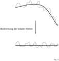
- Fig. 4 schematically illustrates the contour fitting.
- the measured fine contour is shown in dashed lines.
- the rough geometry i.e. the planned contour, is shown in a solid line.
- the illustration is limited to a two-dimensional section.
- Fig. 5 illustrates the determination of the part not hit by the particle beam.
- the profile of the local height over a two-dimensional cutting line is shown above.
- the arrow to the left indicates the determination of the part of the detected surface level that is above a level that is lower than the target level by a predetermined height threshold, and to the right the part that falls below a gradient threshold.
- the level is initially drawn to the left in dotted lines.
- the part that exceeds the level is shown in dashed lines, and the part that falls below it is shown in solid lines.
- the gradient is determined.
- the part that falls below the gradient threshold is shown as a dashed line on the right.
- the upper and lower images are arranged sideways and not offset from one another, while the middle images are offset to the left and right. It can be seen that, for example, the areas at the beginning of the crater are considered to have been treated, even though they still exceed the level, because there is a large gradient at the beginning of the crater. On the other hand, the areas with a lower gradient at the bottom of the crater are also considered to have been treated, because they are (significantly) below the level. This shows that the method enables a particularly reliable assessment.
Landscapes
- Physics & Mathematics (AREA)
- General Physics & Mathematics (AREA)
- Biochemistry (AREA)
- Life Sciences & Earth Sciences (AREA)
- Chemical & Material Sciences (AREA)
- Analytical Chemistry (AREA)
- Health & Medical Sciences (AREA)
- General Health & Medical Sciences (AREA)
- Immunology (AREA)
- Pathology (AREA)
- Engineering & Computer Science (AREA)
- Mechanical Engineering (AREA)
- Length Measuring Devices By Optical Means (AREA)
- Analysing Materials By The Use Of Radiation (AREA)
Claims (4)
- Procédé d'évaluation du résultat d'un traitement de surface effectué sur une pièce par jets de particules, dans lequel(1) La surface traitée par jets de particules est enregistrée de manière résolue dans l'espace au moyen d'une procédé de mesure optique et pour les points de mesure résolus dans l'espace dans chaque casa. un niveau de surface etb. la valeur d'un gradient local par rapport aux points de mesure voisins est déterminée,(2) dans lequel le niveau de surface détecté est comparé à un niveau cible attendu pour la pièce non traitée à l'emplacement du point de mesure et un écart est déterminé, et dans lequel les étapes suivantes sont également exécutées :(3.1) Identifier les points de mesure pour lesquelsa. le niveau de surface détecté conformément à (1) a. est supérieur à un niveau inférieur au niveau cible d'une valeur seuil de hauteur spécifiée, et égalementb. le gradient détecté conformément au point (1) b. est inférieur à un seuil de gradient spécifié,
en tant que points de mesure non touchés par une particule du faisceau de particules,(3.2) Diviser le nombre de points de mesure identifiés en (3.1) comme n'ayant pas été touchés par une particule du faisceau de particules par le nombre total de points de mesure détectés pour déterminer une partie de la surface non touchée par le faisceau de particules. - Procédé selon la revendication 1, caractérisé par le fait que le procédé de mesure optique utilisé est l'interférométrie en lumière blanche, les capteurs de section de lumière laser, un système de chambre stéréo et/ou un procédé Shape-by-Shading.
- Procédé selon l'une des revendications 1 ou 2, caractérisé par le fait que l'enregistrement spatialement résolu de la surface traitée par les jets de particules est réalisé au moyen d'un procédé de mesure optique utilisant un dispositif de mesure optique disposé sur un cobot.
- Procédé selon l'une des revendications précédentes, caractérisé par le fait que les valeurs de la valeur seuil de hauteur et/ou de la valeur seuil de gradient sont déterminées sur la base d'une analyse d'un motif de référence traité avec un faisceau de particules spécifique avec des particules et des paramètres de faisceau prédéterminés et/ou un modèle de simulation d'un motif de traitement créé pour une telle opération de traitement.
Priority Applications (2)
| Application Number | Priority Date | Filing Date | Title |
|---|---|---|---|
| EP22191729.7A EP4328543B1 (fr) | 2022-08-23 | 2022-08-23 | Procédé d'évaluation du résultat d'un traitement de surface effectué sur une pièce par jets de particules |
| US18/453,416 US12517064B2 (en) | 2022-08-23 | 2023-08-22 | Method for assessing the result of a surface treatment performed on a workpiece by particle blasting |
Applications Claiming Priority (1)
| Application Number | Priority Date | Filing Date | Title |
|---|---|---|---|
| EP22191729.7A EP4328543B1 (fr) | 2022-08-23 | 2022-08-23 | Procédé d'évaluation du résultat d'un traitement de surface effectué sur une pièce par jets de particules |
Publications (4)
| Publication Number | Publication Date |
|---|---|
| EP4328543A1 EP4328543A1 (fr) | 2024-02-28 |
| EP4328543A8 EP4328543A8 (fr) | 2024-05-15 |
| EP4328543C0 EP4328543C0 (fr) | 2024-10-23 |
| EP4328543B1 true EP4328543B1 (fr) | 2024-10-23 |
Family
ID=83319239
Family Applications (1)
| Application Number | Title | Priority Date | Filing Date |
|---|---|---|---|
| EP22191729.7A Active EP4328543B1 (fr) | 2022-08-23 | 2022-08-23 | Procédé d'évaluation du résultat d'un traitement de surface effectué sur une pièce par jets de particules |
Country Status (2)
| Country | Link |
|---|---|
| US (1) | US12517064B2 (fr) |
| EP (1) | EP4328543B1 (fr) |
Family Cites Families (21)
| Publication number | Priority date | Publication date | Assignee | Title |
|---|---|---|---|---|
| US3950642A (en) | 1975-05-27 | 1976-04-13 | Metal Improvement Company, Inc. | Method of inspecting shot peened surfaces for extent of coverage |
| US5235517A (en) * | 1991-09-23 | 1993-08-10 | General Electric Company | Measurement of the shot peening coverage by automated analysis of peened surface line traces |
| US5293320A (en) | 1992-03-13 | 1994-03-08 | General Electric Company | Measurment of shot peening coverage by impact dent characterization |
| US5581483A (en) | 1994-09-19 | 1996-12-03 | General Electric Company | Measurement of shot peening coverage by correlation analysis of surface line data |
| JP4314012B2 (ja) * | 2002-10-23 | 2009-08-12 | 株式会社不二製作所 | ブラスト加工条件の検査方法及び検査システム |
| JP5219663B2 (ja) * | 2008-07-10 | 2013-06-26 | 中央発條株式会社 | カバレージを測定する装置、方法、プログラム |
| US8269960B2 (en) * | 2008-07-24 | 2012-09-18 | Kla-Tencor Corp. | Computer-implemented methods for inspecting and/or classifying a wafer |
| JP5182063B2 (ja) | 2008-12-18 | 2013-04-10 | 富士通株式会社 | スイッチ回路及び受信装置 |
| JP5511407B2 (ja) | 2010-01-27 | 2014-06-04 | 東洋精鋼株式会社 | カバレージ測定装置 |
| DE102010001286A1 (de) * | 2010-01-27 | 2011-07-28 | Rolls-Royce Deutschland Ltd & Co KG, 15827 | Verfahren zum Erfassen der Flächenbedeckung beim Kugelstrahlen |
| WO2015008763A1 (fr) * | 2013-07-19 | 2015-01-22 | 旭硝子株式会社 | Procédé de fabrication de verre chimiquement renforcé |
| JP2015160282A (ja) | 2014-02-27 | 2015-09-07 | 中央発條株式会社 | カバレージ測定方法及びカバレージ測定装置 |
| DE102015110289A1 (de) * | 2015-06-26 | 2016-12-29 | Werth Messtechnik Gmbh | Verfahren zur Bestimmung von Messpunkten auf der Oberfläche eines Werkzeugstücks mit einem optischen Sensor |
| PL243870B1 (pl) * | 2016-05-02 | 2023-10-23 | Politechnika Lodzka | Optomechatroniczny sposób bieżącej kontroli jakości obróbki strumieniowo-ściernej |
| FR3065072B1 (fr) | 2017-04-05 | 2019-04-19 | Safran | Procede de determination du taux de recouvrement d'une piece metallique ayant subi un traitement modifiant la rugosite de surface de ladite piece |
| JP6773061B2 (ja) | 2018-02-16 | 2020-10-21 | 新東工業株式会社 | 評価システム、評価装置、評価方法、評価プログラム、及び記録媒体 |
| DE102018132945B4 (de) * | 2018-12-19 | 2020-12-31 | Schott Ag | Plattenförmiger Gegenstand, Verfahren zu dessen Herstellung sowie dessen Verwendung |
| EP3965952B1 (fr) * | 2019-05-09 | 2026-03-25 | Dürr Systems AG | Procédé de contrôle de pièces, installation de contrôle et installation de traitement |
| FR3100336B1 (fr) | 2019-08-28 | 2022-07-29 | Safran | Analyse du recouvrement d’une surface grenaillée |
| DE102020108956B4 (de) | 2020-03-31 | 2022-08-11 | Lufthansa Technik Aktiengesellschaft | Ermittlungsverfahren für Qualitätsparameter und Ermittlungssystem |
| DE102020119149A1 (de) * | 2020-07-21 | 2022-01-27 | Karl Heesemann Maschinenfabrik Gmbh & Co. Kg | Verfahren zum Schleifen einer Oberfläche eines Werkstückes und Vorrichtung dazu |
-
2022
- 2022-08-23 EP EP22191729.7A patent/EP4328543B1/fr active Active
-
2023
- 2023-08-22 US US18/453,416 patent/US12517064B2/en active Active
Also Published As
| Publication number | Publication date |
|---|---|
| US12517064B2 (en) | 2026-01-06 |
| EP4328543C0 (fr) | 2024-10-23 |
| EP4328543A1 (fr) | 2024-02-28 |
| EP4328543A8 (fr) | 2024-05-15 |
| US20240068959A1 (en) | 2024-02-29 |
Similar Documents
| Publication | Publication Date | Title |
|---|---|---|
| DE19849793C1 (de) | Vorrichtung und Verfahren zur berührungslosen Erfassung von Unebenheiten in einer gewölbten Oberfläche | |
| EP2040026B1 (fr) | Procédé et système de calibrage d'un appareil de mesure de la forme d'une surface réfléchissante | |
| DE102007016056B4 (de) | Verfahren und Vorrichtung zur Werkstückeinmessung und Werkstückbearbeitung | |
| DE3505331C2 (de) | Verfahren und Gerät zur Vermessung des bei der Eindringhärteprüfung in einer Probe hinterlassenen Eindrucks | |
| EP1332334B2 (fr) | Dispositif de mesure servant a effectuer des mesures sans contact sur des pneumatiques | |
| EP1342073B1 (fr) | Dispositif et procédé pour positionner un défaut d'un pneu | |
| EP3432266A1 (fr) | Procédé et dispositif de détection de défauts | |
| DE102013003760A1 (de) | Verfahren und Vorrichtung zur Qualitätsbeurteilung eines mittels eines generativen Lasersinter- und/oder Laserschmelzverfahrens hergestellten Bauteils | |
| EP3956736B1 (fr) | Procédé mis en oeuvre par ordinateur pour la détermination de défauts d'un objet fabriqué au moyen d'un processus de fabrication additive | |
| EP3417237B1 (fr) | Plaque de référence et procédé pour calibrer et/ou vérifier un système de détection par déflectométrie | |
| EP2495525A1 (fr) | Procédé de vérification optique à l'aide d'un déroulement d'intensité | |
| EP4151948A1 (fr) | Procédé et dispositif de contrôle de la qualité d'un bord d'une pièce à usiner en forme de plaque | |
| DE19951146A1 (de) | Verfahren zum Reduzieren des Rauschens in einem durch Abbildung erhaltenen Signal | |
| EP0586795A1 (fr) | Dispositif et procédé pour la détermination sans contact de la rugosité de surface de matériaux | |
| EP2031348B1 (fr) | Procédé d'inspection de surfaces destinée à détecter des défauts de surface et/ou mesurer la topographie de surface | |
| EP4328543A1 (fr) | Procédé d'évaluation du résultat d'un traitement de surface effectué sur une pièce par jets de particules | |
| DE4324800C2 (de) | Vorrichtung zur Bestimmung von Fehlern von Oberflächen hoher Güte | |
| EP3885078A1 (fr) | Balayage de surface hyperspectrale d'un corps | |
| DE10151332B4 (de) | Vorrichtung zur optischen Messung von Oberflächeneigenschaften | |
| DE102008049859B4 (de) | Verfahren und Prüfsystem zur optischen Prüfung einer Kontur eines Prüfobjekts | |
| DE102024201510A1 (de) | Verfahren und Vorrichtung zum Ermitteln einer optischen Reflektivität einer gekrümmten Oberfläche eines optischen Prüflings | |
| DE102017103037A1 (de) | Verfahren zur zerstörungsfreien Untersuchung und Klassifizierung eines metallischen Werkstücks | |
| EP4339556A1 (fr) | Procédé et dispositif de détermination de propriétés de surface d'une pièce | |
| DE102024121562A1 (de) | Verfahren zur automatisierten bildbasierten erfassung von knotenpunkten eines kontrastliniengitters | |
| DE102023201749A1 (de) | Verfahren zum Trainieren eines Ensemble Algorithmus des maschinellen Lernens zum Klassifizieren von Bilddaten |
Legal Events
| Date | Code | Title | Description |
|---|---|---|---|
| PUAI | Public reference made under article 153(3) epc to a published international application that has entered the european phase |
Free format text: ORIGINAL CODE: 0009012 |
|
| STAA | Information on the status of an ep patent application or granted ep patent |
Free format text: STATUS: REQUEST FOR EXAMINATION WAS MADE |
|
| 17P | Request for examination filed |
Effective date: 20230718 |
|
| AK | Designated contracting states |
Kind code of ref document: A1 Designated state(s): AL AT BE BG CH CY CZ DE DK EE ES FI FR GB GR HR HU IE IS IT LI LT LU LV MC MK MT NL NO PL PT RO RS SE SI SK SM TR |
|
| RBV | Designated contracting states (corrected) |
Designated state(s): AL AT BE BG CH CY CZ DE DK EE ES FI FR GB GR HR HU IE IS IT LI LT LU LV MC MK MT NL NO PL PT RO RS SE SI SK SM TR |
|
| RIN1 | Information on inventor provided before grant (corrected) |
Inventor name: ERNST, MICHAEL Inventor name: DOMASCHKE, TOMAS Inventor name: FLUEH, TOBIAS Inventor name: REIMER, LARS Inventor name: JANSSEN, ANTON |
|
| GRAP | Despatch of communication of intention to grant a patent |
Free format text: ORIGINAL CODE: EPIDOSNIGR1 |
|
| STAA | Information on the status of an ep patent application or granted ep patent |
Free format text: STATUS: GRANT OF PATENT IS INTENDED |
|
| RIC1 | Information provided on ipc code assigned before grant |
Ipc: B24C 1/10 20060101ALN20240517BHEP Ipc: G01B 11/24 20060101ALN20240517BHEP Ipc: G01B 9/0209 20220101ALN20240517BHEP Ipc: G01B 11/28 20060101ALI20240517BHEP Ipc: G01B 11/30 20060101AFI20240517BHEP |
|
| INTG | Intention to grant announced |
Effective date: 20240613 |
|
| GRAS | Grant fee paid |
Free format text: ORIGINAL CODE: EPIDOSNIGR3 |
|
| GRAA | (expected) grant |
Free format text: ORIGINAL CODE: 0009210 |
|
| STAA | Information on the status of an ep patent application or granted ep patent |
Free format text: STATUS: THE PATENT HAS BEEN GRANTED |
|
| AK | Designated contracting states |
Kind code of ref document: B1 Designated state(s): AL AT BE BG CH CY CZ DE DK EE ES FI FR GB GR HR HU IE IS IT LI LT LU LV MC MK MT NL NO PL PT RO RS SE SI SK SM TR |
|
| REG | Reference to a national code |
Ref country code: GB Ref legal event code: FG4D Free format text: NOT ENGLISH |
|
| REG | Reference to a national code |
Ref country code: CH Ref legal event code: EP |
|
| REG | Reference to a national code |
Ref country code: DE Ref legal event code: R096 Ref document number: 502022001955 Country of ref document: DE |
|
| REG | Reference to a national code |
Ref country code: IE Ref legal event code: FG4D Free format text: LANGUAGE OF EP DOCUMENT: GERMAN |
|
| U01 | Request for unitary effect filed |
Effective date: 20241113 |
|
| U07 | Unitary effect registered |
Designated state(s): AT BE BG DE DK EE FI FR IT LT LU LV MT NL PT RO SE SI Effective date: 20241120 |
|
| PG25 | Lapsed in a contracting state [announced via postgrant information from national office to epo] |
Ref country code: HR Free format text: LAPSE BECAUSE OF FAILURE TO SUBMIT A TRANSLATION OF THE DESCRIPTION OR TO PAY THE FEE WITHIN THE PRESCRIBED TIME-LIMIT Effective date: 20241023 Ref country code: IS Free format text: LAPSE BECAUSE OF FAILURE TO SUBMIT A TRANSLATION OF THE DESCRIPTION OR TO PAY THE FEE WITHIN THE PRESCRIBED TIME-LIMIT Effective date: 20250223 |
|
| PG25 | Lapsed in a contracting state [announced via postgrant information from national office to epo] |
Ref country code: ES Free format text: LAPSE BECAUSE OF FAILURE TO SUBMIT A TRANSLATION OF THE DESCRIPTION OR TO PAY THE FEE WITHIN THE PRESCRIBED TIME-LIMIT Effective date: 20241023 |
|
| PG25 | Lapsed in a contracting state [announced via postgrant information from national office to epo] |
Ref country code: NO Free format text: LAPSE BECAUSE OF FAILURE TO SUBMIT A TRANSLATION OF THE DESCRIPTION OR TO PAY THE FEE WITHIN THE PRESCRIBED TIME-LIMIT Effective date: 20250123 |
|
| PG25 | Lapsed in a contracting state [announced via postgrant information from national office to epo] |
Ref country code: GR Free format text: LAPSE BECAUSE OF FAILURE TO SUBMIT A TRANSLATION OF THE DESCRIPTION OR TO PAY THE FEE WITHIN THE PRESCRIBED TIME-LIMIT Effective date: 20250124 |
|
| PG25 | Lapsed in a contracting state [announced via postgrant information from national office to epo] |
Ref country code: PL Free format text: LAPSE BECAUSE OF FAILURE TO SUBMIT A TRANSLATION OF THE DESCRIPTION OR TO PAY THE FEE WITHIN THE PRESCRIBED TIME-LIMIT Effective date: 20241023 |
|
| PG25 | Lapsed in a contracting state [announced via postgrant information from national office to epo] |
Ref country code: RS Free format text: LAPSE BECAUSE OF FAILURE TO SUBMIT A TRANSLATION OF THE DESCRIPTION OR TO PAY THE FEE WITHIN THE PRESCRIBED TIME-LIMIT Effective date: 20250123 |
|
| PG25 | Lapsed in a contracting state [announced via postgrant information from national office to epo] |
Ref country code: SM Free format text: LAPSE BECAUSE OF FAILURE TO SUBMIT A TRANSLATION OF THE DESCRIPTION OR TO PAY THE FEE WITHIN THE PRESCRIBED TIME-LIMIT Effective date: 20241023 |
|
| PG25 | Lapsed in a contracting state [announced via postgrant information from national office to epo] |
Ref country code: SK Free format text: LAPSE BECAUSE OF FAILURE TO SUBMIT A TRANSLATION OF THE DESCRIPTION OR TO PAY THE FEE WITHIN THE PRESCRIBED TIME-LIMIT Effective date: 20241023 |
|
| PG25 | Lapsed in a contracting state [announced via postgrant information from national office to epo] |
Ref country code: CZ Free format text: LAPSE BECAUSE OF FAILURE TO SUBMIT A TRANSLATION OF THE DESCRIPTION OR TO PAY THE FEE WITHIN THE PRESCRIBED TIME-LIMIT Effective date: 20241023 |
|
| PLBE | No opposition filed within time limit |
Free format text: ORIGINAL CODE: 0009261 |
|
| STAA | Information on the status of an ep patent application or granted ep patent |
Free format text: STATUS: NO OPPOSITION FILED WITHIN TIME LIMIT |
|
| U20 | Renewal fee for the european patent with unitary effect paid |
Year of fee payment: 4 Effective date: 20250811 |
|
| 26N | No opposition filed |
Effective date: 20250724 |
|
| REG | Reference to a national code |
Ref country code: CH Ref legal event code: H13 Free format text: ST27 STATUS EVENT CODE: U-0-0-H10-H13 (AS PROVIDED BY THE NATIONAL OFFICE) Effective date: 20260324 |
|
| PG25 | Lapsed in a contracting state [announced via postgrant information from national office to epo] |
Ref country code: MC Free format text: LAPSE BECAUSE OF FAILURE TO SUBMIT A TRANSLATION OF THE DESCRIPTION OR TO PAY THE FEE WITHIN THE PRESCRIBED TIME-LIMIT Effective date: 20241023 |
|
| PG25 | Lapsed in a contracting state [announced via postgrant information from national office to epo] |
Ref country code: CH Free format text: LAPSE BECAUSE OF NON-PAYMENT OF DUE FEES Effective date: 20250831 |
|
| PG25 | Lapsed in a contracting state [announced via postgrant information from national office to epo] |
Ref country code: IE Free format text: LAPSE BECAUSE OF NON-PAYMENT OF DUE FEES Effective date: 20250823 |
|
| U20 | Renewal fee for the european patent with unitary effect paid |
Year of fee payment: 5 Effective date: 20260624 |